

MTD 218-360 User Manual

Model No. 218-360
)fomMeiU'
MTD
ROTARY TILLER
WARRANTY
For one year from date of purchase, MTD Products Inc will replace for the original purchaser, free
of charge, F.O.B. factory or authorized service firm, any part or parts found to be defective in material
or workmanship. All transportation charges on parts submitted for replacement under this warranty must
be paid by the purchaser. This warranty does not include replacement of parts which become inoperative
through misuse, excessive use, accident, neglect, improper maintenance or alterations by unauthorized
persons. This warranty does not include the engine, motor, battery, battery charger or any component
parts thereof. For service on these units refer to the applicable manufacturer’s warranty.
The above warranty will apply only to the original owner and will be effective only if the warranty
card has been properly processed. It will not apply where the unit has been used commercially.
Warranty service is available through your local authorized service dealer or distributor. UNDER NO
CIRCUMSTANCES WILL THE RETURN OF A COMPLETE UNIT BE ACCEPTED BY THE FACTORY
UNLESS PRIOR WRITTEN PERMISSION HAS BEEN EXTENDED.
SAFETY RULES
Your rotary tiller is a precision built machine designed to take the work out of gardening and other
related chores. It can be used for seed bed preparation, tilling, cultivating, furrowing, composting and
mulching. Like any other piece of power equipment, it requires a certain amount of care and mainte
nance. In return for this, it will give a maximum of service and efficiency. Read these instructions
carefully before assembling or operating your tiller. Through proper care and operation, you will obtain
long, efficient service and trouble free operation.
1. Your tiller is a precision piece of power equip
ment. Exercise extreme caution at all times.
2. Do not attempt to start engine with the clutch
control in engaged or “Forward” position.
3. Stand clear of tines when starting engine. Never
stand in front of, or work on tines while the
engine is running.
4. NEVER place hands or feet in the vicinity of
the tines while the engine is running.
5. Always stop engine when tiller is not in actual
use.
6. Always disconnect spark plug wire during re
pairs or refueling operations.
7. Do not fill gas tank while engine is running.
Do not spill gasoline on hot engine.
FROIDUCTS I2STC • 5389 west 130th ST. • P.O. box 2741 • CLEVELAND, OHIO 44111
FORM NO. 770-1345A
102 86 100
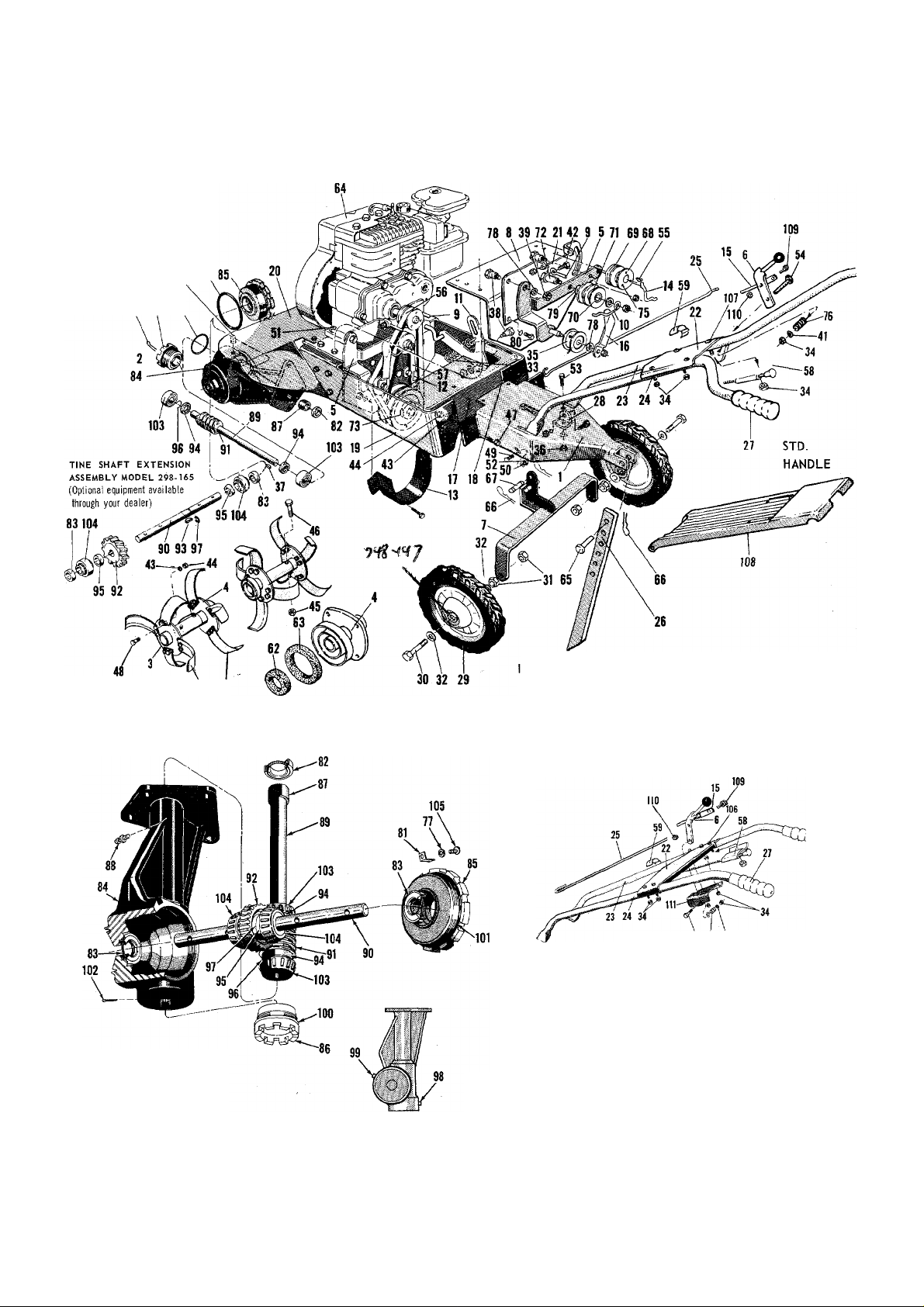
Tiller Model 218-360
98 101
60 61
GEAR CASE ASSEMBLY
321-4102
FORM NO. 770-1345B
er Tine Assembly - R. H.
Inner Tine Assembly - L. H.
Outer Tine Assembly — R. H. — Complete 901-4298
Outer Tine Assembly - L. H. — Complete 901-4297
PLOW TYPE HANDLE
When ordering replacement parts, be sure to specify your mower model number,
port number, description of part, and the number of ports required . . . Parts and
service should be handled by your nearest authorixed service firm as recom
mended by your dealer. Request for parts and service received at the factory
will be forwarded to the appropriate Central Service Distributor in your.area for
handling.
Complete 901-4296
Complete 901-4295
54 76 41

MODEL 218-360
Ulus.
No.
1 395-4330
2
3
4
5
6
7
8
9
10
Port
No.
321-4102-1
395-4265
395-4266
310-4168
310-4164
321-4172
395-4170
310-4149
310-4151
Tailpiece Assembly
Gear Case Assembly (Complete)
Outer Tine Adapter Assembly
Inner Tine Adapter Assembly
Reverse Pivot Bracket Assembly
Control Handle Assembly
Wheel Hanger Assembly
Engine Mounting Plate
Belt Retainer
Belt Retainer 66
11 310-4158 Control Lever
310-4148
12
321-4162 Belt Guard 69
13
Belt Clip
( ) - No. Required Per Assembly
DESCRIPTION
Ulus.
No.
58
746-122
746-110
58
59
746-111
60
742-113
61 742-110 Tine - R. H.
62 736-124
63
736-125 Dust Pad
—
64
65
711-231
714-106
67
711-137
756-104 Pulley
68
717-109
14 310-4155 Control Rod 70 748-111
310-8271 Adjustment Tube 71
15
310-4147 Belt’ Clip
16
17 395-4114
1819395-4112
395-4113
20 312-4261
310-4167
21
395-4243
22
395-4121
22
23 310-4246
23 310-4186
Rear Frame
Side Frame — R. H.
Side Frame — L. H.
Dust Shield
Adjustment Plate
Handle Panel — Small — Std. Handle
Handle Panel — Plow Type
Handle - R. H. - Std.
Handle — Plow Type — R. H.
24 310-4247 Handle - L. H. - Std.
310-4143
24
711-213 Control Rod
25
321-4328
26
27 305-1166
310-4124
28
29 501-8929
30
710-275
31 712-384
32 736-108
732-376 Spring — Tension
33
712-107
34
756-370 Idler Bearing Assembly
35
712-372
36
37 714-314
38 710-373
712-430 Hex Elastic Stop Nut 3/8—16 thd.
39
40 712-123
736-463 Washer 9/32 I.D. *
41
42 710-258
43 736-169
712-798
44
712-116
45
46 710-113
Handle — Plow Type — L. H.
Depth Bar
Grip
Handle Mounting Bracket
Wheel Assembly
Hex Hd. Cap Sew. 1/2—13 x 5 Ig.*
Hex Centerlock Nut 1/2—13 thd. *
Washer 33/64 I.D.*
Hex Centerlock Nut 1/4—20 thd.*
Hex Centerlock Nut 5/16—18 thd.*
Key — Hi Pro #606
Shoulder Bolt
Hex Nut 5/16-24 thd. *
HexHd. Cap Sew. 1/4—20 x 5/8 Ig.*
Lockwasher 3/8 Screw *
Hex Nut 3/8— 16 thd. *
Hex Eiastic Stop Nut 3/8 — 24
HexHd. Cap Sew. 3/8—24 X 1-5/8 Ig.
Heat Treated *
710-253
47
710-183
48
49 710-451
50 7.36-119
51 710-442
712-267
52
710-118
53
710-136
54
714-105
55
56
754-104
57 .
754-103
HexHd. Cap Sew. 3/8—16 x 1 Ig. *
HexHd. Cap Sew. 3/8—i6 x 1-1/8 Ig.*
Carriage Bolt 5/16—18 x 3/4 Ig. *
Lockwasher 5/16 Screw *
HexHd. Cap Sew. 5/16-18 x 1-1/2 Ig. *
Hex Nut 5/16-18 thd.*
HexHd. Cap Sew. 5/16—18 x 3/4 Ig.*
HexHd. Cap Sew. 1/4-20 x T-3/4 Ig. *
Key - Square 3/16 x 3/16 x 1 Ig.*
“V” Belt 1/2 X 32 - Gates *
“V” Belt 1/2 X 27 - Gates *
756-112 Pulley — 2 Stage
72 711-138 Shoulder Screw
73 756-108 Pulley — 2 Stage
74 710-765 Set Screw — Allen 5/16—24 x 1/4 Ig.
75
710-185 Allen Socket Head Cap Screw 10—32x 1 Ig.*
76 732-958 Spring — Compression
77
736-147 Lockwasher #10 Screw *
736-300
78
736-466
79
80
710-122 Hex Hd. Cap Sew. 5/16—24 x 1 Ig.*
81 310-4101
82 721-100
83 721-101
84 719-100
719-lOlR
85
719-102
86
87
748-106 Bronze Sleeve Bearing t
88
737-108 Alemite Drive Fitting #1992-B1 * t
89
711-132 Worm Shaft - 3/4” t
90
711^133
91 717-104
92
717-105 Worm Wheel t
93 714-103
711-130
94
95 711-131 Spacer-1” t
96 716-101
97 716-102 Snap Ring - Tru Arc #5100-175 * t
98 737-102 Pipe Plug - Special Breather Type t
737-103
99
100 735-100
735-101
101
102
714-474 Cotter Pin 1/8 Dia. x 3/4 Ig. * t
741-107
103
104
741-108 Roller Bearing - Timken 1” t
710-125 Rd. Hd. Mach. Sew. 10-24 x 1/2 Ig. * t
105
107 710-256 Carriage Bolt 1/4—20 x 1-1/2 Ig. *
108 395-4257
109 710-252
712-324
110
395-4160
111
901-4295
901-4296
901-4297 Outer Tine Ass’y - L.H. - Complete
901-4298
727-112 Lubricant 5 oz. (Gear Case)
Part
No.
DESCRIPTION
( ) - No. Required Per Assembly
Control - Throttle (complete) Std. Handle
Control - Throttle (Plow Type Handle)
Cable Clip
Tine - L. H.
Dust Pad
Engine
Clevis Pin
Locking Pin
Support Pin
Reverse Drive Wheel
Bronze Sleeve Bearing
(Not Shown)
Washer 3/8 I.D.*
Washer 17/32 I.D.*
Locking Clamp t
Oil Seal - Garlock #76 x 6113 t
Oil Seal - Garlock #78 x 7510 t
Housing — Gear Case t
Bearing Adjustment Cap - 1”
Bearing Adjustment Cap - 3/4” t
Tine Shaft - 1” t
Worm t
Key - Woodruff #91 * t
Spacer - 3/4'* t
Snap Ring - Tru Arc #5100-75 * t
Pipe Plug - Square Head 3/8 thread * t
”0” Ring 2-1/8 X 2-3/8 x 1/8 t
“O” Ring 3-5/8 X 3-7/8 x 1/8 t
Roller Bearing - Timken 3/4” t
Handle Panel (Large) Std. Handle Only
Hex Hd. Cap Sew. 1/4—20 x 3/4 Ig. *
Hex Stop Nut 1/4—20 thread *
Control Mtg. Brkt.-Plow Type Handle
Inner Tine Ass’y - L.H.-Complete
Inner Tine Ass’y-R.H. - Complete
Outer Tine Ass’y-R.H.-Complete
* For faster service obtain standard nuts, bolts and washers locally. If these items cannot be obtained locally, order by
part number and size as shown on parts list,
t Part of Gear Case Assembly (Complete) 321-4102-1.
FORM NO. 770-1345C
 Loading...