

Page 1
ASSEMBLY
OPERATION
TEN CENTS
ANUAL
Model Nos.
217-100A
MAINTENANCE
PARTS LIST
Important:
Read Safety Rules and
Instructions Carefully
217-100-300
VERTICAL
ROTARY
TILLERS
PRINTED IN U.S.A.
FORM NO. 770-6788
Page 2

IMPORTANT
It is suggested that this manual be read in its entirety before attempting to assemble or operate. Keep this
manual in a safe place for future reference and for ordering replacement parts.
This unit is shipped WITHOUT GASOLINE or OIL. After assembly, see operating section of this manual
for proper fuel and amount.
Your tiller is a precision piece of power equipment, not a play thing. Therefore exercise extreme caution at
all times.
SAFE OPERATION PRACTICES FOR TILLERS
1. Read the Operating and Service Owner’s
Manual carefully. Be thoroughly familiar with
the controls and the proper use of the equip
ment.
2. Never allow children to operate a power tiller.
Only persons well acquainted with these rules
of safe operation should be allowed to use
your tiller.
3. Keep the area of operation clear of all
persons, particularly small children and pets.
4. Do not operate equipment when barefoot or
wearing open sandals. Always wear substan
tial footwear.
5. Do not wear loose fitting clothing that could
get caught on the tiller.
6. Do not start the engine unless the shift lever
is in the neutral (N) position.
11. Do not fill gasoline tank while engine is
running. Spilling gasoline on hot engine may
cause a fire or explosion.
12. Do not run the engine while indoors. Exhaust
gases are deadly poisonous.
13. Be careful not to touch the muffler after the
engine has been running, it is hot.
14. Before any maintenance work is performed or
adjustments are made, remove the spark plug
wire and ground it on the engine block for
added safety.
15. Use caution when tilling near buildings and
fences, rotating tines can cause damage or
injury.
16. Before attempting to remove rocks, bricks
and other objects from tines, stop the engine
and be sure the tines have stopped
completely. Disconnect the spark plug wire
and ground to prevent accidental starting.
7. Do not stand in front of the tiller while
starting the engine.
8. Do not place feet and hands on or near the
tines when starting the engine or while the
engine is running.
9. Do not leave the tiller unattended with the
engine running.
10. Do not walk in front of the tiller while the
engine is running.
17. Check the tine and engine mounting bolts at
frequent intervals for proper tightness.
18. Keep all nuts, bolts and screws tight to be
sure the equipment is in safe working
condition.
19. Never store the equipment with gasoline in
the tank inside of a building where fumes may
reach an open flame or spark. Allow the
engine to cool before storing in any
enclosure.
Page 3

ASSEMBLY
Your rotary tiller is shipped complete in a single
carton. The tines, wheels, handle and depth bar
are to be assembled. This is done in the manner
described below.
Tines—Mount tines on tine shaft as shown. (See
page 10.) Tines must be mounted with the cutting
edges facing the correct direction. The tiller will
not operate properly unless the sharpened surface
of the tines enter the soil first. Secure tines in
position on tine shaft with cap screws (41), and
nuts (32).
Wheels—Insert axle bolts (23) into wheel hubs.
Place washers (26) between wheel and leg. Attach
wheel and axle assemblies to outside of tiller legs
(27) and (30). Secure with nuts (29) and
lockwashers (28). Tighten securely. See page 8 for
correct sequence of parts.
Handle—Assemble the handle brackets (8) to
the handle (2) with hex head screw (11),
lockwashers (9) and hex nuts (10). DO NOT
tighten. Place the handle brackets (8) in the
tailpiece slots. Line up lower holes in handle
brackets with mounting holes in tailpiece
assembly. Secure with carriage bolt 5/16-18 x
3/4” Lg. (20), lockwasher (13) and hex nut (12).
Line up upper holes in handle brackets with
mounting holes in mounting plate assemblies (19)
and secure with carriage bolt (20), lockwasher (13)
and hex nut (12). See page 8 for correct sequence.
Tighten all nuts and bolts securely.
CHECK LIST BEFORE OPERATION
A. After the tiller is assembled and before
gasoline and oil are added to the engine, check
the case for correct lubricant level.
1. Remove rear pipe plug from tiller gear case.
See figure 1.
Pipe Plug
IS
Adjustable
Wrench
FIGURE 1.
2. If lubricant flows from the outlet, lubricant
is at the correct level. See figure 2.
CLUTCH CONTROL LEVER ASSEMBLY
Clutch Lever—Assemble in this order: rubber
washer (42), steel washer (41), clutch lever
assembly (43), (rod bracket to the front), steel
washer (41) and lock nut (40). Tighten until rubber
washer compresses slightly. (See page 8.)
Clutch Control Assembly—Screw the ferrule (37)
on the threaded end of the control rod (38) until
about Vz" of the threads show above the ferrule.
Insert the ferrule through the control pivot lever
(36), fasten with flat washer (35) and cotter hairpin
(34). Put the clutch handle in the neutral position.
Insert the control rod in the bracket on the clutch
lever and secure with a cotter hairpin (34) through
the center of the bracket. Adjust the ferrule so the
belt Is slack when the clutch lever is in the neutral
position. (See page 8.)
Depth Bar—Attach depth bar (18) in desired
position with clevis pin (17) and locking pin (15).
(See page 8.)
Grips—Slip hand grips on the upper end of each
handle. They will slip on more easily if you first
soak them in warm soapy water.
FIGURE 2.
3. If lubricant fails to flow from the outlet,
lubricant should be added. USE PENNANT
OIL EP #35000. This is available in 8 ounce
squeeze tubes. Order part number
737-0136. See figure 3.
FIGURES.
Page 4

B. Remove spark plug wire from spark plug and
ground. Check tiller tines for proper installa
tion. With throttle control lever set on STOP
position and the clutch control handle set in
FORWARD position, slowly crank engine to
determine direction of tine rotation. Be sure all
tines are mounted so the sharpened edges
enter the soil first.
C. Now place the clutch control handle in
NEUTRAL position. Slowly crank engine. The
tines should not rotate.
D. Check all nuts and bolts for proper tightness.
This is especially important during the initial
operation period. Make this same check
periodically thereafter.
E. Fill fuel tank with clean, fresh, regular grade
gasoline. This should be used at all times.
F. Check engine crankcase for proper oil level.
The engine is shipped without oil in the
crankcase. Be sure to fill crankcase before
starting engine. Be sure crankcase is FULL.
See engine manual for correct type and
amount.
Hi^ NOTE
The engine is warranted separately
by the engine manufacturer. For
warranty service contact the engine
manufacturer or their local author
ized service station. All important
information pertaining to care and
operation is included in the engine
manual.
STARTING YOUR TILLER
1. Be sure clutch control handle is in NEUTRAL
position.
2. Move throttle lever to START position on
engine.
3. After cranking the engine several times or as
the engine fires, move the throttle lever to
RUN position.
4. Adjust throttle lever for desired operating
speed.
5. To stop engine, move throttle lever to STOP
position. Keep throttle lever in STOP position
at all times when tiller is not in use.
NOTE
A brief break-in period is essential
to insure maximum engine life. This
consists of running the engine at
half speed for a period of time re
quired to use one tank of gasoline.
This is necessary on the initial run
only. It is also recommended that
the oil be changed after five (5) hours
of operation. This allows for the re
moval of impurities which may have
accumulated during the break-in
period. Subsequent oil changes
should be made as stated in the en
gine manual. Always check oil be
fore using your tiller. Be sure oil lev
el is adequate.
OPERATING
INSTRUCTIONS
For your own convenience and safety, observe all
safety suggestions shown in this manual. Your
tiller is not a toy, it is a precision piece of power
equipment. Treat it as such.
It is important to recognize the fact that the
forward and penetrating action of the rotary tiller
is obtained from the rotating action of the tines
in the soil. The depth bar acts as a brake for the
tiller and controls the depth and speed at which
the machine will operate. By lowering the setting
of the depth bar, the forward speed of the machine
is reduced and the working depth of the tines is
increased. Raising the setting of the depth bar
increases the forward speed and reduces the
working depth. When soil conditions are severe
and several passes must be made over a certain
area, the depth bar setting should be lowered each
time a pass is made. Further control of tilling
depth and travel speed can be obtained by
variation of pressure on the handles or the throttle
setting. A downward pressure on the handles will
increase the working depth and reduce the
forward speed. An upward pressure on the
handles will reduce the working depth and
increase the forward speed. The type of soil and
working conditions will determine the actual
setting of the depth bar and the handle pressure
required.
1. Tine engagement and forward travel is
achieved by moving the clutch lever to
FORWARD position. Tine rotation and
forward motion are stopped by moving the
clutch lever to NEUTRAL position.
Page 5
2. The throttle lever adjusts the engine speed. It
also gives fingertip control of the carburetor
and magneto stop switch. When the throttle
lever is pushed completely to the right from
behind the tiller, the carburetor is in START
position. Pulling the lever to the left reduces
the engine speed to SLOW. When the lever is
pulled completely to the left from behind the
tiller, the magneto stop switch grounds out
the spark and stops the engine.
3. When the depth bar is positioned out of
ground engagement, self-propelled trans
porting of the tiller is easily achieved. With no
pressure on the handles and the throttle lever
set for SLOW engine speed, move the clutch
control handle to the FORWARD position and
let the tiller gently propel itself.
1. Standard tine arrangement
2. Remove tines that point outward from outer
tine assemblies. Tines may be interchanged
with opposite sides..........................................20”
3. Add tine extensions to standard arrangement
(See page 6.).................................................. 40”
NOTE
When adjusting tines, be sure the
cutting edges enter the soil first.
....
........................
26”
MAINTENANCE AND LUBRICATION
Engine—Service engine in accordance with the
engine manufacturer's owner’s guide.
ADJUSTMENTS
Belts—Belt slack is taken up by a spring loaded
idler pulley. Because of this, belt adjustment is
not required.
Clutch—No adjustment of the lower clutch rod is
required. This is done automatically by the spring
loaded idler.
NOTE
Belt and clutch adjustments can be
made by moving the engine bed.
Loosen the four bolts which secure
it and move the engine bed forward
or backward as required. Adjusting
the control rod will also effect the
belt and clutch adjustment. These
adjustments may be necessary if
handle position is changed.
Handle—The position of the handle may be
adjusted by removing and moving carnage bolts
to the desired mounting holes. Adjustment
should be made for the most convenient operating
height.
Wheels—Wheel positions may be varied to give
further adjustment of handle height. Various
wheel positions also give variations of the
leverage and weight distribution over the tines.
Wheels should be set to suit the local soil
conditions and the operator’s convenience.
Tines—The standard width of cut is 26”. Because
of the various types of work to which the tiller may
be put, variation in the tilling widths may be
necessary. This can be accomplished in a number
of ways.
NOTE
To drain oil, remove oil filler plug
and tip tiller on its side. Drain oil
while the engine is warm. See en
gine manual for filling instructions.
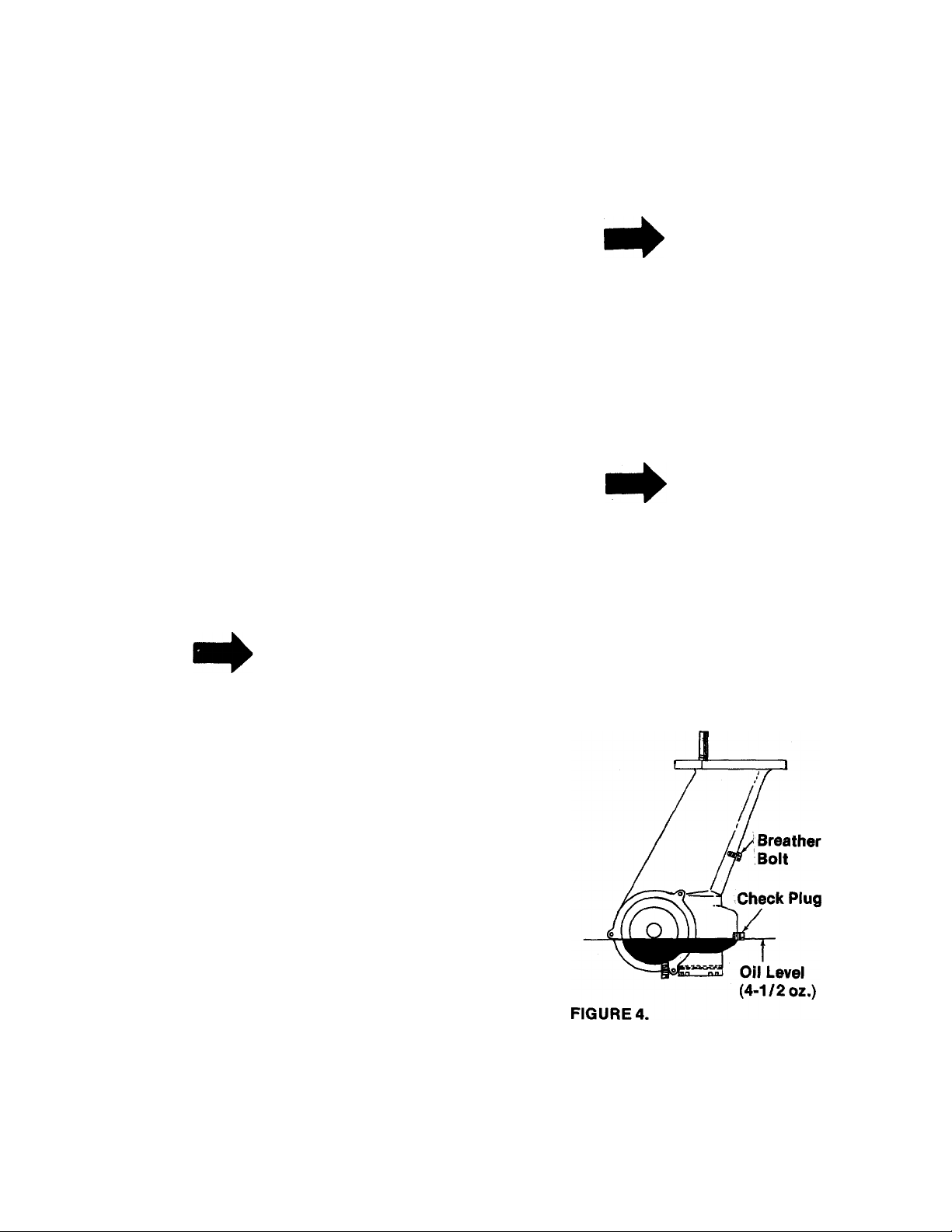
Gear Case—Whenever disassembly of gear case
is required, gear case should be thoroughly
cleaned and lubricated with 4V2 ounces of
PENNANT OIL EP #35000. This is available in 8
ounce squeeze tubes. Order part number
747-0136. See figure 4.
Belt—Access to V belt and pulley assemblies is
accomplished by removing the engine and engine
bed as described below.
1. Remove four cap screws which secure engine
bed to mounting plate assembly. Remove
engine bed with engine attached.
Page 6

2. Remove hex screw, lockwasher and flatwasher in 41/2” pulley. Remove pulley and “V” belt.
The belt clip on idler must be loosened to
remove belt, mark correct location of belt clip
in relation to idler before loosening. This can
be done by scribing the belt clip and the end
of the weld bolt in idler with a file. It is most
important that this clip be reassembled in the
right position.
3. Position new belt on 4V2” pulley and reinstall
on gear case shaft. Pulley must be mounted
in position so that it will line up with engine
pulley when assembly is completed. The
correct position is that point at which the
center of the pulley is 1-1/8” above the
mounting plate assembly. Tighten hex screw,
lockwasher and flat washer securely.
4. Line up the belt clip in original position and
tighten securely. Make sure belt is inside belt
guards. While holding the belt taut (grasp at
extreme rear position), move clutch belt lever
to FORWARD and NEUTRAL position. If belt
clip touches belt with lever in either position,
readjust position of clip.
5. Move clutch lever to NEUTRAL position.
Remove inspection plate from engine bed.
6. Replace engine bed on mounting plate
assembly. Move engine bed and engine as far
forward as possible.
7. Remove inspection plate (See page 10.) from
engine bed and reach through inspection hole
and guide belt into position on engine pulley.
8. Check visually through inspection hole to
make sure belt is inside all belt guards and
that pulleys are in proper alignment. A
flashlight will help you make this check
quickly and easily.
9. Line up mounting holes of engine bed and
mounting plate then replace cap screws. Do
not tighten cap screws until all four screws
are in place. Replace inspection plate.
7. Dip oil seals in lubricant and then insert one
in gear case and one in bearing cap.
8. Wipe tine shaft clean of filings and lubricate
before assembling with bearings and worm
wheel in gear case.
Replace bearing cap.
9.
^ CAUTION
Do not damage oil seals. The open
flanges face to the outside of the
gear case.
10. Tighten bearing cap, retighten screws evenly.
11. Replace tine assemblies and add lubricant.
(See pages.)
General—Check periodically all nuts and bolts.
Loose nuts and bolts can cause permanent
damage to your unit. Keep all nuts and bolts
securely tightened.
STORAGE
The following steps should be taken to prepare
your tiller for storage.
1. Clean tiller thoroughly and lubricate as
described in the preceding instructions.
2. Coat tilling tines with grease to prevent
rusting.
3. Prepare engine for storage in accordance with
engine manufacturer’s owner’s guide.
4. Block tiller legs to raise tires clear of floor. Be
sure tiller is level.
5. Store in a dry, clean area.
ATTACHMENTS
REPLACING TILLER GEAR CASE OIL SEALS
1. Drain lubricant.
2. Remove tine assemblies.
3. Remove bearing cap. (See reference 17 on
page 12.)
4. Remove bearings, worm wheel and tine shaft.
Do not remove bearing races.
5. Remove oil seals from gear case and bearing
cap.
6. Remove all burrs from holes in tine shaft.
Extension Tines—This attachment is available to
increase your tilling width up to 40”. Extension
tines are easily installed and removed. Order
under part number 297-162A.
Furrow Opener—This attachment is easily
installed on the depth bar of your tiller. It can be
used for either furrowing or hilling operations.
These attachments are available through your
local dealer.
For wide (2” x .43”) depth bar, order furrow opener
297-179A.
Page 7

TINE CHART
BOLO TINES
(have a square plate with four (4) tines)
12” Bolo Tines
for Gear Case
Models
04701
04702
04293
04294
742-0105
742-0106
04683
04673
Inner tine ass’y. L.H.
Inner tine ass’y- R-H.
Outer tine ass’y. L.H.
Outer tine ass’y. R.H.
Tine only L.H.
Tine only R.H.
Outer tine adapter
Inner tine adapter
SLASHER TINES
(have a round plate with eight (8) bolts)
14” Slasher
Tines for Gear
Case Models
with 1” tine
shaft
04677
04678
04297
04298
742-0113
742-0110
04265
04674 \
Inner tine ass’y. L.H.
Inner tine ass’y. R.H.
Outer tine ass’y. L.H.
Outer tine ass’y. R.H.
Tine only L.H.
Tine only R.H.
Outer tine adapter
Inner tine adapter
Page 8

217-100A
IF YOU WRITE TO US ABOUT THIS ARTICLE
OR IF YOU ORDER REPLACEMENT PARTS AL
WAYS MENTION THIS MODEL & SERIAL NO
MODEL
^0 29 28
Page 9

REF.
NO.
PART
NO.
COLOR
CODE
PARTS LIST FOR MODEL 217-100A
DESCRIPTION
NEW
PART
REF.
NO.
PART
NO.
COLOR
CODE
DESCRIPTION
NEW
PART
1 01166
04624
2
—463
8 04386 —463
736-0169 L-Wash. 3/8” Scr.*
9
10
712-0798
11
710-0253
Grip—Black
Handle Ass’yHandle Mount Brackets
Hex Nut 3/8-16 Thd.*
Hex Scr. 3/8-16x1.00” Lg.*
12 712-0267 Hex Nut 5/16-18Thd.*
13 736-0119 L-Wash. 5/16” Scr.*
14
710-0118
732-0194
15
04329
16
17
711-0231 Clevis Pin .500” Dia.
04668
18
04124
19
710-0276
20
—463
—463
—463
Hex Scr. 5/16-18 X.75” Lg.*
Spring Pin
Tail Piece Ass’y.
Depth Bar
Handle Mount Brackets
Carriage Bolt 5/16-18x1.00”
Lg.*
21 736-0119
22 712-0267
23
738-0318 Shoulder Scr. .625” Dia. x
24 741-0116
L-Wash. 5/16” Scr.*
Hex Nut 5/16-18 Thd.*
2.75(1/2-20 Thd.)
Fiange Brg. with Flats .631
I.D.
25
734-0585
‘For faster service, obtain standard nuts, bolts and \washers locaily. If these items cannot be ob
tained locaiiy, order by part number and size as sho\«n on parts list.
Wheel Ass’y. 9.0x1.75
26 736-0253
Belleville Wash. .505 I.D. x
1.00O.D.
27
04109
—463
Leg—Left Hand
28 736-0921 L-Wash. 1/2” Scr.*
29
712-0239
04110
30
04691
31
32 747-0148
33 738-0183
—463
—463
Hex Nut 1/2-20Thd.*
Leg—Right Hand
Mounting Plate Ass’y.
Lower Control Rod
Shoulder Scr. .500” Dia. x
.215
34 714-0115
35 736-0204
36 04619
37
711-0392
38
711-0502
39
720-0143
40
712-0158
Cotter Pin 1 /8” Dia. x 1.00”
Lg-*
FI-Wash. .344” I.D. X .62 O.D
Control Pivot Lever
Adjustment Ferrule
Control Rod 20”
Grip—Black
Hex Inserted L-Nut 5/16-18
Thd.
736-0159 Fl-Wash. .344I.D. X.88 0.D.
41
42
735-0126
Rubber Wash. .33 I.D. x .87
O.D.
43
04392
Clutch Lever Ass’y.
(463—Top Fiite Red)
When ordering parts if color or finish is important, use the appropriate coior
code shown at ieft. (e.g. Top Fiite Red Finish—04624 (463) )
Find u* fast in
The engine is not under warranty by the tiller manufacturer. If repairs or service is
needed on the engine, please contact your nearest authorized engine service outlet. Check
the “Yellow Pages” of your telephone book under “Engines^asoline.”
Page 10

217-100A
INNER TINE ASS’Y.—COMP.—L.H. 04701 Optional Tine
INNER TINE ASS’Y.—COMP.—R.H. 04702 Extension—Order
OUTER TINE ASS’Y.—COMP.-L.H. 04293 Part No. 297-162A
OUTER TINE ASS’Y.—COMP.—R.H. 04294 04673
10
NOTE
Due to specification changes on tiller
tines, the tines on your tiller may be
different than the ones shown here.
When ordering replacement parts, see
tine chart on page 7.
Page 11

REF.
NO.
1
2
3
PART
NO.
04258 —312
04126
710-0128
COLOR
CODE
DESCRIPTION
Engine Bed
Inspection Plate
Hex F-Tapp Scr. #10-32 x .50”
Lg.*
—
4
5
710-0158
6
756-0248
7
750-0284
8 736-0117
9
04259
10
736-0169
11
710-0152
15
710-0259
Engine
Hex Scr. 5/16-24 x 1.25” Lg.*
Sheave 3.0” x .50
Spacer
FI-Wash. .385” I.D. x .62 O.D.
Engine Shaft Spacer
L-Wash.3/8”Scr.*
HexScr. 3/8-24x1.00” Lg.*
Hex Sems Scr. 5 /16-18 x .62”
Lg.‘
17
736-0119
18
712-0123
24
712-0181 Hex Top L-Nut 3/8-16 Thd. *
25
710-0600
L-Wash. 5/16” Scr.*
Hex Nut 5/16-24 Thd.*
Hex Wash.-Hd. Self Tapp.
Scr. 5/16-24 X .50” Lg.
04204
26
27
04688
28 738-0183
Belt Pusher
Idler Brkt. Ass’y.
Shoulder Scr. .500” Dia. x
.215
04673
31
32 712-0116
33 04683
34 710-0191
742-0105
35
36
742-0106
37
736-0169
Inner Tine Adapter Ass’y.
Hex Center L-Nut 3/8-24 Thd.
Outer Tine Adapter Ass’y.
Hex Scr. 3/8-24 X1.25” Lg. *
Tine 12”—Left Hand
Tine 12”—Right Hand
L-Wash. 3/8” Scr.*
PARTS LIST FOR MODEL 217-100A
PART
NEW
PART
REF.
NO.
38
39
40
41
42
45
46
47
49
50
51
52
53
54
60
61
62
63
64
65
66
67
70
04196
712-0107
756-0370
736-0300
712-0158
712-0241
736-0169
712-0798
710-0539
714-0126
04197 —463
04691 —463
712-0107
716-0119
756-0249
736-0231
736-0119
710-0118
732-0233
712-0107
07353
747-0148
754-0196
NO.
COLOR
CODE
71 714-0105
711-0599
72
DESCRIPTION
Hex Nut 3/8-24 Thd.*
L-Wash.3/8”Scr.*
Hex Nut 3/8-16 Thd.*
HexScr. 3/8-24x1.75” Lg.
H.T.
#9 Hi-Pro-Key 3/16 X Va” Dia
Belt Guard
Mounting Plate Ass’y.
Hex Cent. L-Nut V4-20Thd.
Snap Ring ¥4” Dia. Shaft
Pulley—Double Groove 4.50”
O.D.
FI-Wash. .344x1.125
L-Wash. 5/16”Scr.*
HexScr. 5/16-18X.75” Lg.*
Spring Extension .62 O.D. x
4.94 Lg.
Hex Cent. L-Nut V4-20Thd.
Hold Down Clamp
Hex Cent. L-Nut V4-20 Thd.
Idler Bearing Ass’y.
FI-Wash. .385” I.D. x .870”
O.D.
Belt Clip
Hex Cent. L-Nut 5/16-18 Thd
Lower Control Rod
V-Belt 1/2” X 30” Lg. (Forward
Belt) Fiber “B”
Sq. Key3/16x3/16x1.00”
Lg.
Clevis Pin
NEW
PART
‘For faster service, obtain standard nuts, bolts and washers locally. If these items cannot be
obtained locally, order by part number and size as shown on parts list.
(463—Top Flite Red)
When ordering parts if color or finish is important, use the appropriate color
code shown at left, (e.g Top Flite Red Finish—04624 (463) )
Find us fsst In
The tiller is not under warranty by the tiller manufacturer. If repairs or service is
needed on the engine, please contact your nearest authorized engine service outlet. Check
the "Yellow Pages” of your telephone book under "Engines-Qasoline.”
11
Page 12

217-100A
GEAR CASE ASSEMBLY 717-0305
PARTS LIST FOR GEAR CASE ASSEMBLY 717-0305
PART;
REF.
NO.
1 716-0119
2 721-0100
741-0197
3
4
710-0599
5 736-0222 Ext. L-Wash. V4”
6 737-0103
7
741-0189
736-0259
3
9 714-0103
10
711-0622
11
716-0102
12
717-0311
13
736-0119
14
721-0102
15 710-0371
NO.
COLOR
CODE
DESCRIPTION
Snap Ring .75” Dia. Shaft
Oil Seal .75” Dia. Shaft
Sleeve Brg. .752 I.D. x .878
O.D. xl.OO” La.
Hex Wash. Self-Tapp. Scr.
Sq. Hd. Pipe Plug 3/8” Thd.*
Flange Brg. 1.00 I.D.
FI-Wash. 1.00” I.D. X 1.62”
O.D. X .095
#91 Woodruff Key V4 x 3/4”
Dia.
Tine Shaft 1.00” Dia.
Snap Ring fori .00” Dia. Shaft X.502
Worm Wheel
L-Wash.5/16”Scr.*
Oil Seal Double Lip 1.00”
Shaft
Hex Scr. 5/16-18 X.88” Lg.
(Plastic Insert)
NEW
PART
This improved tiiier gear case is not equipped with the
conventional type breather plug. In its piace is an assembly
made up of a self tapping screw and a star type washer. This
system allows adequate relief of built up pressure within the
gear case. It also reduces lubricant leakage to a minimum.
See figure 1.
NOTE: Use4V2 ounces of Pennant Oil EP#35000.
Order Part No. 737-0136.
REF.
NO.
736-0261
16
741-0188
17
735-0101
18
714-0474 Cotter Pin 1/8” Dia. X.75”
19
10583
20
21 735-0100
741-0107
22
716-0101 Snap Ring for .75” Dia. Shaft
23
24 711-0469
714-0126
25
717-0312
26
738-0171 Worm Shaft
27
719-0223
28
PART
NO.
COLOR
CODE
DESCRIPTION
Wash.—Flat Toothed
(Special)
Bearing Cap with Bearing
“0”-Ring3.62” I.D. X 3.88
O.D. X .12
Lg.*
Bearing Adjustment Cap
“0”-Ring 2.12 I.D. X 2.28
O.D. X .12
Roller Brg. Ass’y. -75 I.D.
Spacer .755 I.D. X1.265 O.D.
#9 Hi-Pro Key 3/16 X .75” Dia.
Worm
Gear Case
NEW
PART
_
‘For faster service obtain standard nuts, bolts and washers locally. If these items cannot be obtained locally, order by part
number and size as shown on parts list.
12
Page 13

217-100A
TILLER DRIVE
MECHANISM
Engine Pulley Assembly
Control Rod
747-0148
V-Belt 1/2x30
754-0196
Gear Box Pulley
756-0249
Spring 732-0233
Belt Pusher 04204
Idler Bracket 04688
Belt Clip 07353
Idler Pulley 756-0370
Belt Guard 04197
Hex Screw 710-0116
13
Lockwasher 736-0119
Flatwasher 736-0231
Page 14

Page 15

Page 16

MRTS INFORMATION
POWER EQUIPMEKT PARTS AND SERVICE
Ports and service for oil MTD manufactured power
equipment are available through the authorized service
firms listed below. All orders should specify the model
number of your unit, parts numbers, description of ports
and the quantity of each part required.
ALABAMA BIRMINGHAM
Auto Elactric&Carburetor Co...2625 4th Ave. S................. 35233
ARKANSAS NORTH LITTLE ROCK
Sutton's Lawn Mowor Shop
Mity Mito Motors, Inc;
CALIFORNIA SAN BERNARDINO
Lawn Mower Supply Co
J.W. Jewett Co
Luttip & Severson
COLORADO DENVER
South Denver Lawn Equip
CONNECTICUT SUFFIELD
The Jones & Romsey Co
FLORIDA JACKSONVILLE
Rodeo Distributors
Moz'All of Florida, Inc
GEORGIA EAST POINT
East Point Cycle & Key .......... 2834 Church St
ILLINOIS LYONS
Keen Edge Co
INDIANA ELKHART
Ports & Sales Inc........................ 2101 Industrial Pkwy. ..46514
IOWA DUBUQUE
Power Lawn 8i Gordon Equip. .2551 J.F. Kennedy ....52001
KANSAS WICHITA
Hixon, Inc. ....■............................ 3030 Mascot
LOUISIANA NEW ORLEANS
Suhren Engine Co
MARYLAND TAKOMA PARK
Canter Supply Co
MASSACHUSETTS SPRINGFIELD
Morton B. Collins Co
MICHIGAN MOUNT CLEMENS
Power Equipment Dist
Lorenz Service Co
MINNESOTA MINNETONKA
Hance Distributing Inc.................11212 Wayzata Blvd. ..55343
MISSISSIPPI BILOXI
Biloxi Sales 8i Service, Inc.—506 Caillavet St
MISSOURI KANSAS CITY
Automotive Equip. Service
Henzier, Inc................................ 2015 Lomoy Ferry Rd. 63125
NEW YORK CARTHAGE
Gamble Diet., Inc
Kimber's, Inc
..........................
.....................
...........................
.....................
...................
.....................
.......................
...............................
........
FORT SMITH
................
.............
SAN FRANCISCO
SACRAMENTO
.....................
CORAL GABLES
.................
.................
...............
LANSING
ST. LOUIS
SYRACUSE
Rt. 4, Box 368
2515 Towson Ave
25608 E. Baseline .... 92410
981 Folsom St
2030 28th St
.........
527 West Evans
...........
850 Thompsonville Rd. 06078
2403 Morhet St
365 Greco Ave
8615 Ogden Ave...........60534
8330 Earhart Blvd
6867 Now Hampshire Ave. 20012
300 Birnie Ave
36463 South Uratiot... 48043
2500 S. Ponnsylvonia .. 48900
.........
3117 Holmes St
West End Ave
115 N. Geddes St
..............
.........
..............
................
...........
............
.............
.............
..............
........
..............
..................
............
.............
.........
72117
72901
94107
95818
80223
32206
33146
30344
67204
70118
01107
39533
64109
13619
13204
BRIGGS & STRATTON, TECUMSEH AND PEERLESS PARTS AND SERVICE
Briggs & Strotton, Tecumseh and Peerless parts and
service should be handled by your nearest authorize
engine service firm. Check the yellow pages of you.
telephone directory under the listing Engines
Gasoline, Briggs & Stratton or Tecumseh Lauson
NORTH CAROLINA GREENSBORO
Dixie Sales Company .................327 Battleground Ave.. 27402
Smith Hordworo Co
OHIO WADSWORTH
Notional Central
Bleckrie, Inc................................ 7900 Loroin Ave
Stobe's Mid-State Mower Supply Box 366
Sunshine Wholesale Tire Outlet Route 224
McClure Lown & Garden Supply...! 114 Lexington Ave. . 44903
OKLAHOMA MUSKOGEE
Victory Motors, Inc
Ada Auto Supply
OREGON PORTLAND
Kenton Supply Co........................8216 N. Denver Ave. . 97217
PENNSYLVANIA LANCASTER
Roub Supply Co. .....................
Bluemont Co.............................. 11125 Frankstown Rd.. 15235
TENNESSEE KNOXVILLE
Master Repair Service
Memphis Cycle & Supply Co
American Soles & Service, Inc.. 1922 Lynnbrook
TEXAS DALLAS
Marr Brothers, Inc
Bullard Supply Co...................... 2409 Commerce St
Cotto & Putty, Inc
Woodson Sales Corp
UTAH SALT LAKE CITY
A-1 Engine 8. Mower Co
VERMONT BURLINGTON
Vermont Appliance Co
VIRGINIA RICHMOND
RBI Corp
WASHINGTON SEATTLE
Bailey's Rebuild, Inc
WEST VIRGINIA CHARLESTON
Young's, Inc
WISCONSIN APPLETON
Automotive Supply Co
....................................
................................
GOLDSBORO
....................
.........................
CLEVELAND
CARROL
WILLARD
MANSFIELD
......................
ADA
........................
PITTSBURGH
..............
MEMPHIS
......
......................
HOUSTON
SAN ANTONIO
.......................
FORT WORTH
.................
............
................
..................
................
515 N. George St
687 Seville Rd
605 S. Cherokee
301 E. 12fh St
James & Mulberry Sts... 17604
2423 Broadway, N.E. ..37917
421 Monroe Ave
423 E. Jefferson
P.O. Box 2408 ...............78206
1702 N. Sylvania
437 E. 9th St
44 Lakeside Ave
963 Myers St.................. 23260
1325 E. Madison St. ...98102
233 Virginio St., E. ...25301
123 S. Linwood Ave. ..54911
______________
___________
.........
.............
...........
........................
.....................
........
..............
............
.............
............
........
...........
..................
..........
27530
44281
44102
43112
44890
74401
74820
381C3
38116
75 203-^
770v
76111
84111
05401
WARRANTY PARTS AND SERVICE POLICY
The purpose of worron^ is to protect the customer from defects in workmanship and materials, defects which are NOT detected
at the time of manufacture. It does not provide for the unlimited ond unrestricted replacement of ports. Use and maintenance are
the responsibility of the customer. The manufacturer cannot assume responsibility for conditions over which it has no control.
Simply put, if it’s the manufacturer's fault, it’s the manufacturer’s responsibility; if it’s the customer's fault, it’s the customer's
responsibility.
CLAIMS AGAINST THE MANUFACTURER’S
WARRANTY INCLUDES
1. Replacement of Missing Ports on new equipment. 1. Model Number of unit involved.
2. Replocement of Defective Ports within the warranty period. 2. Dote unit was purchased or first put into service.
3. Repair of Defects within the warranty period. 3. Dote pf failure.
u
INC • 5389 WEST 130th STREET • P. 0. BOX 2741 CLEVELAND OHIO 44111
All claims MUST be substantiated with the following
information;
4. Noture of failure.
 Loading...