

MTD 216-406-000 User Manual
Summer
1.00
REAR TINE
TILLERS
(With Reverse Drive)
important:
Read Safety Rules and
Instructions Carefully
Modei Numbers
216-403-000
216-406-000
Thank you for purchasing
an American-built product.
PRINTED IN U.S.A. FORM NO. 770-5251A

INDEX
Safe Operation Practices
Assembly ....................................................................... 4
Controls ..........................................................................
Operation
How To Use Your Tiller....................................................9
Adjustments....................................................................10
.....................
.............................................
.....
.................................................9
Instructions given with this symbol are for personal
A
safety. Be s ure to follow them.
r
LIMITED WARRANTY
♦
♦
♦
♦
♦
♦
♦
♦
♦
For one year from the date of orig nal retail purchase, MTD PRODUCTS INC will either
repair or replace, at its option, free c f charge, F.O.B. factory or authorized service firm, any
part or parts found to be defective in material or workmanship. Transportation charges for
the movement of any power equipm(;nt unit or attachment are the responsibility of the pur
chaser. Transportation charges for eny parts submitted for replacement under this warran
ty must be paid by the purchaser unless such return is requested by MTD PRODUCTS INC.
This warranty will not apply to any fiart which has become inoperative due to misuse, ex
cessive use, accident, neglect, imp oper maintenance, alterations, or unless the unit has
been operated and maintained in ac jordance with the instructions furnished. This warran
ty does not apply to the engine, motor, battery, battery chargeror component parts thereof.
Please refer to the applicable manufacturer’s warranty on these items.
This warranty will not apply where ihe unit has been used commercially.
3
8
Lubrication
Maintenance................................................................. 12
Off-Season Storage
Illustrated Parts
Parts List
Parts Information............................................Back Cover
.....................................................................
........................................................
..................................
......................................
16, 18, 20, 21, 22
17, 18, 19, 20, 21, 22
11
14
♦
♦
♦
♦
♦
♦
t
♦
♦
♦
♦
Warranty service is available througn your local authorized service dealer or distributor. If
you do not know the dealer or distributor in your area, please write to the Customer Service
Department of MTD.
The return of a complete unit will not be accepted by the factory unless prior written per
mission has been extended by MTC .
♦
♦
This warranty gives you specific legal rights. You may also have other rights which vary
from state to state.
V
AC WARNING I
This unit is equipped with an internal combustion engine and should not be used on or near any unim
proved forest-covered, brush-covered or cirass-covered land unless the engine’s exhaust system is
equipped with a spark arrester meeting app icable local or state laws (if any). If a spark arrester is used, it
should be maintained in effective working srder by the operator.
In the State of California the above is required by law (Section 4442 of the California Public Resources
Code). Other states may have similar Ipws. F ederal laws apply on federal lands. A spark arrester muffler is
available at your nearest engine authorized service center.
♦
♦
♦
♦
♦

WARNING
Ac
t
To reduce the potential for any injury, comply with the following safety instructions. Failure to comply
with the instructions may result in personal injury.
SAFE OPERATION PRACTICES FOR TILLERS
1. It is suggested that this manual be read in its
entirety before attempting to assemble or
operate this unit. Keep this manual in a safe
place for future and regular reference and for
ordering replacement parts.
2. Your tiller is a precision piece of power equip
ment, not a plaything. Therefore, exercise ex
treme caution at all times.
3. Read this Owner’s Manual carefully. Be
thoroughly familiar with the controls and the
proper use of the equipment.
4. Never allow children to operate a power tiller.
Only persons well acquainted with these rules
of safe operation should be allowed to use
your tiller.
5. No one should operate this unit while intoxi
cated or while taking medication that impairs
the senses or reactions.
6. Keep the area of operation clear of all per
sons, particularly small children and pets.
14. Do not walk in front of the tiller while the
engine is running.
15. Check the fuel before starting the engine.
Gasoline is an extremely flammable fuel. Do
not fill gasoline tank indoors, while the engine
is running, or while the engine is still hot.
Replace gasoline cap securely, and wipe off
any spilled gasoline before starting the
engine as it may cause a fire or explosion.
16. Do not run the engine while indoors. Exhaust
gases are deadly poisonous.
17. Be careful not to touch the muffler after the
engine has been running. It is hot.
18. Do not change the engine governor settings
or overspeed the engine. Excessive engine
speeds are dangerous.
19. Before any maintenance work is performed or
adjustments are made, remove the spark plug
wire and ground it on the engine block for
added safety.
7. Do not operate equipment when barefoot or
wearing open sandals. Always wear substan
tial footwear.
8. Do not wear loose fitting clothing that could
get caught on the tiller.
9. Do not start the engine unless the shift lever
is in the neutral (N) position.
10. Do not stand in front of the tiller while starting
the engine.
11. Do not place feet and hands on or near the
tines when starting the engine or while the
engine is running.
12. Never attempt to make a wheel or depth bar
adjustment while the engine is running.
13 Do not leave the tiller unattended with the
engine running.
20. Use caution when tilling near buildings and
fences. Rotating tines can cause damage or
injury.
21. Before attempting to remove rocks, bricks and
other objects from tines, stop the engine and
be sure the tines have stopped completely.
Disconnect the spark plug wire and ground to
prevent accidental starting.
22. Check the tine and engine mounting bolts at
frequent intervals for proper tightness.
23. Keep all nuts, bolts and screws tight to be
sure the equipment is in safe working condi
tion.
24. Never store the equipment with gasoline in
the tank inside of a building where fumes may
reach an open flame or spark. Allow the
engine to cool before storing in any
enclosure.
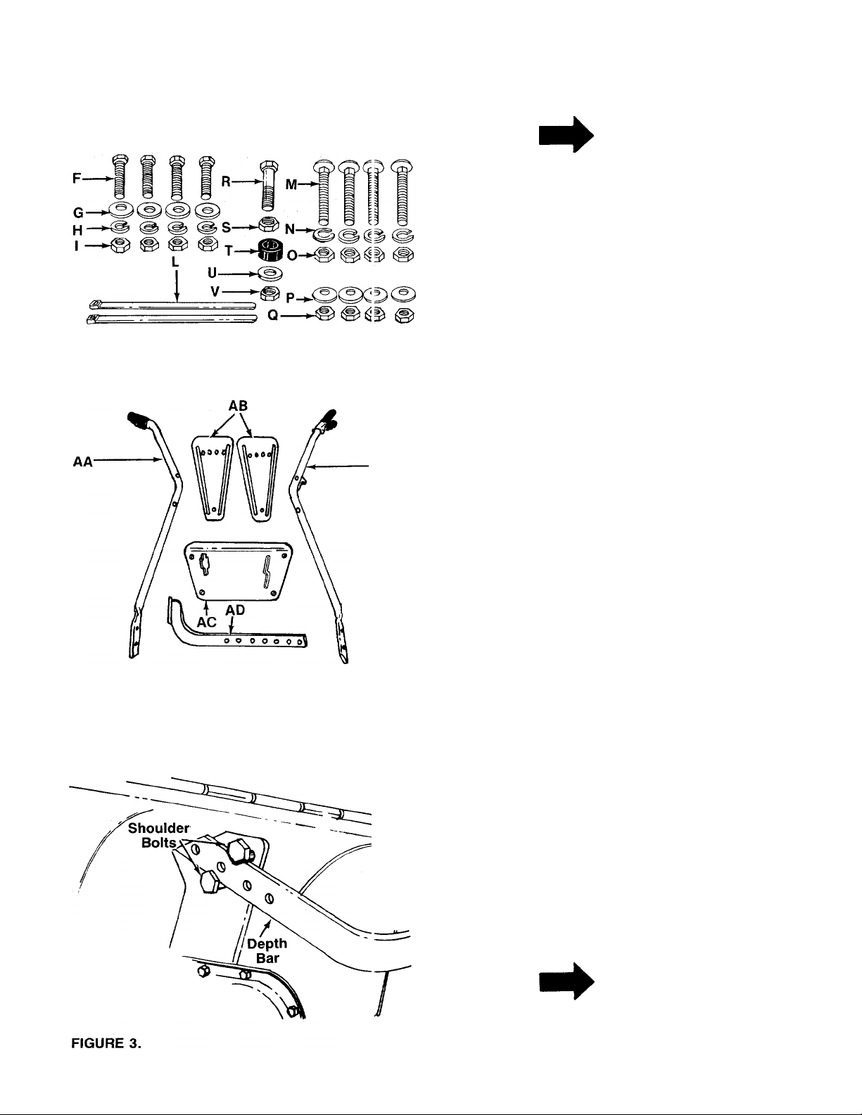
FIGURE 1.
FIGURE 2.
B-
E--
AE
ASSEMBLY
NOTE
This unit is shipped WITHOUT GAS
OLINE or OIL. After assembly, see
separate engine manual for proper
fuel and engine oil recommenda
tions.
■Contents of Hardware Pack: (See Figure 1)
A
B
C
D
E
F
G
H
I
L
M
N
O
P
Q
R
S
T
u
V
w
X
■Loose Parts in Carton: (See figure 2)
AA (1) Handle—R.H.
AB (2) Side Shields
AC (1) Handle Panel
AD (1) Depth Bar Assembly
AE (1) Handle—L.H.
1. Remove tiller, loose parts and hardware pack from
2. Extend the control cables attached to the tiller and
Hex Bolt 3/8-16 X 3/4" Long
(1)
Flat Washer 3/8" I.D.
(1)
Ball Knob
(1)
Clevis Pin
(1)
Hairpin Cotter
(1)
Hex Bolts 3/8-16 X 1.0"
(4)
Belleville Washers 3/8"
(4)
Lock Washers 3/8" I.D.
(4)
Hex Nuts 3/8-16 Thread
(4)
Cable Ties
(2)
Carriage Bolts 5/16-18 x 1.75" Long
(4)
Lock Washers 5/16" I.D.
(4)
Hex Nuts 5/16-18 Thread
(4)
Belleville Washers 5/16" I.D.
(4)
Hex Nuts 5/16-18 Thread
(4)
Hex Bolt V4-28 x 1" Long
(1)
Hex Lock Nut V4-28 Thread
(1)
Rubber Washer
(1)
Flat Washer 5/16" I.D. x 7/8" O.D.
(1)
Hex Lock Nut 5/16-18 Thread
(1)
Drive Clutch Lever (Not Shown)
(1)
Self-Tapping Screw (Not Shown)
(1)
carton. Make certain all parts and literature have
been removed from the carton before the carton
is discarded.
place on the floor. Be careful not to bend or kink
the cables.
Long
I.D.
DEPTH BAR INSTALLATION
1.
-----
/
-------
Raise the tine shield hinge flap assembly. Insert
the depth bar assembly (AD) between the two
shoulder bolts and up through the tine shield
assembly as shown in figure 3.
NOTE
For clarity, figure 3 was taken with
tiller raised on end. It is not neces
sary to raise the tiller.
End Cover
Ball Knob
Flat
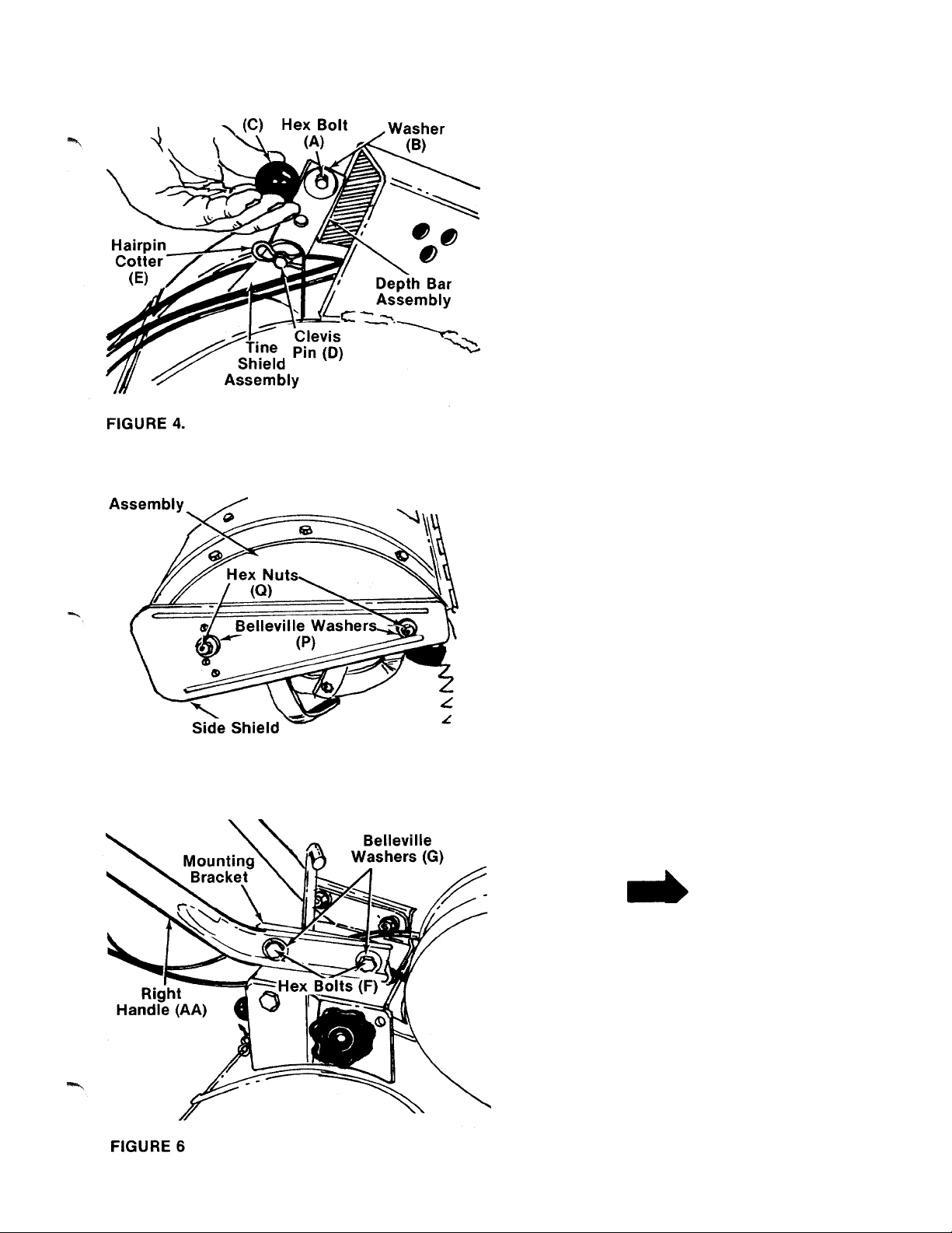
2. Insert clevis pin (D) through the tine shield and
depth bar assemblies. Secure with hairpin cotter
— (E). See figure 4.
3. Insert hex bolt (A) into the upper hole of the depth
bar assembly. Place flat washer (B) onto the hex
bolt and thread ball knob (C) onto the hex bolt. See
figure 4. Tighten securely.
FIGURE 5.
SIDE SHIELD INSTALLATION
Mount side shields (AB) over the weld bolts on the end
cover assemblies. Secure with belleville washers (P)
■and hex nuts (Q). See figure 5.
HANDLE ASSEMBLY
NOTE
Left and right is determined from
the operator’s position, standing
behind the tiller.
1. Place right handle (AA) in position on the right side
of the tiller. Insert hex bolts (F) through belleville
washers (G), handle and mounting bracket. See
-----
figure 6. Secure with hex nuts (I) and lock washers
(H).
2. Repeat step 1 for left handle (AE) on the left side
of the tiller.
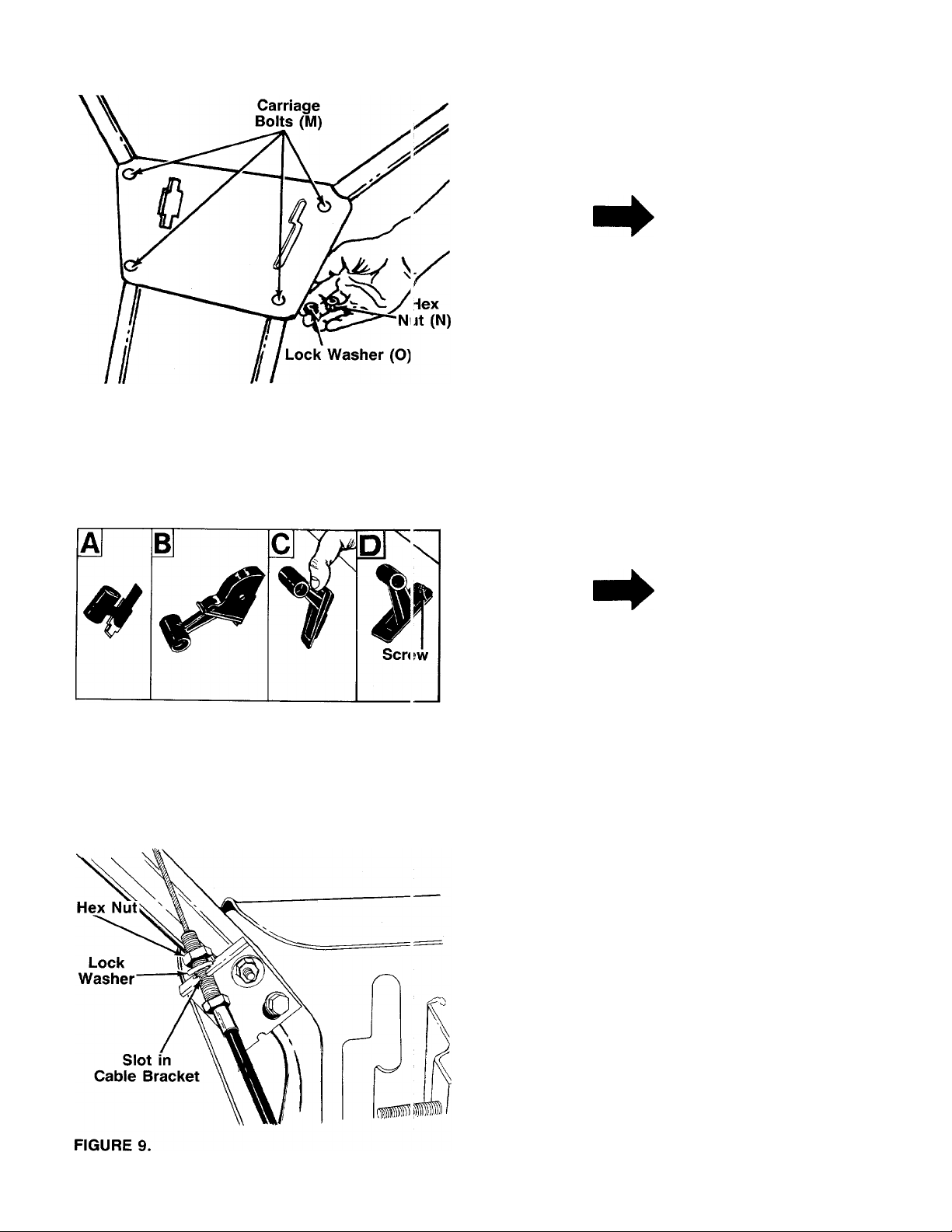
FIGURE 7.
3.
Mount the handle panel (AC) to the handles.
Secure with carriage bolts (M), lock washers (N)
■ and hex nuts (O). See figure 7.
Secure the throttle control to the handle panel
using the self-tapping screw (X). See figure 8D.
NOTE
To align the holes in the handle
panel and the handle, it may be
necessary to loosen the cable
brackets which are mounted to the
back of the handles with self
tapping screws.
THROTTLE CONTROL INSTALLATION
Assemble the throttle control to the handle panel as
follows.
1.
Hold the throttle control assembly beneath the han
dle panel. Turn the control sideways and insert the
lever up through the wide portion of the slot on the
handle panel. See figure 8A.
After the end of the lever is through the slot, turn
and then tip the control forward as shown in figure
-8B to slide it through the slot.
FIGURE 8.
NOTE
The lever must be all the way to the
back of the control housing as
shown in figure 8B.
3.
Push the control back into the slot in the handle
panel and press in place. Be certain the control is
locked securely into the slot.
4. Secure the throttle control to the handle panel
using the self-tapping screw (X). See figure 8D.
ATTACHING THE TINE CLUTCH CONTROL CABLE
The clutch control cables are already attached to the
unit. The tine clutch control cable has a “Z” fitting on
the loose end. This cable attaches to the left handle.
■I^NOTE
Both the drive clutch cables and the
tine clutch cable are attached to
springs, which are hooked to bolts.
If either the cable or spring has
come loose in shipping, it must be
reassembled. Refer to page 18, ref
erence numbers 2, 5, 11, 12, 15, 17
and 21.
1.
Remove one nut and the lock washer from the end
of the tine clutch cable (short cable). Slip the cable
up through the slot on the cable bracket on the left
handle. Rethread hex nut and lock washer on the
■end of the cable. See figure 9. Do not tighten at
this time.

FIGURE 10.
Hole in
2.
Hook the “Z” end of tine clutch cable into the hole
in tine clutch lever.
With the clutch lever released (in the “up” posi
3.
tion), adjust the bottom nut at the cable bracket so
there is only a slight amount of slack in the control
wire. Tighten the upper nut against the bracket.
Squeeze the clutch lever against the handle. The
■control wire should now be straight. See figure 10.
NOTE
Do not overtighten control wire.
Too much tension may cause it to
break.
ATTACHING THE DRIVE CONTROL CABLES
1. The drive clutch cables are already attached to the
unit. Attach the other end of cables to the upper
hole of drive clutch lever (W), one on each side,
using hex bolt (R) and hex lock nut (S). See figure
11.
2. Remove one nut and the lock washer from the end
of each drive clutch cable. Thread the other hex
nut all the way down the cable as far as it will go
as shown in figure 11.
FIGURE 11.
Gripped End of
Clutch Lever
FIGURE 12.
Slots on
Cable Bracket
3.
Push the gripped end of drive clutch lever through
the slot in the handle panel.
4.
Slip the wire on the cables through the slots in the
cable brackets as shown in figure 12. Push the
ends of the cable up through the holes in the
bracket. Rethread hex nuts and lock washers on
the end of the cables. Do tighten at this time.
Place end of drive clutch lever over weld bolt on
5.
handle panel. See figure 12.

FIGURE 13.
6. Secure drive clutch lever to weld bolt with rubber
washer (T), flat washer (U) and hex lock nut (V).
— See figure 13. Tighten hex nut.
Place the drive clutch lever in the neutral (N) posi
7.
tion. Adjust the cables at the cable bracket so that
the cables are tight, then tighten the hex nuts
against the cable bracket.
IMPORTANT
Service engine with oil and gasoline
before checking the drive clutch
adjustment. Refer to the separate
engine manual packed with your
tiller.
8.
Check the adjustment of the drive clutch as follows.
Place the unit against a solid object (wall, fence,
etc.). With the tine clutch lever released and the
drive clutch lever In the neutral position, carefully
start the engine. If the unit shows any signs of mo
tion with the drive clutch lever in neutral, shut the
engine off immediately and readjust the hex nuts
at the cable bracket. Recheck the adjustment as
necessary.
9.
Secure the cables to the handles as with cable ties
(L). Cut off excess ends of cable ties.
CONTROLS —Location and Use
Throttle Control
The throttle control lever is located on the right hand
side of handle panel and controls the engine speed.
See figure 14.
1. Start—Push throttle control lever forward (down)
to start position.
2. Stop—Pull lever back (upward) to stop the e igine.
/
Tine Ciutch Lever
The tine clutch lever is located on the left handle. See
figure 14.
Squeeze the lever down to engage the tines. Release
the lever to disengage the tines.
Drive Ciutch Lever
The drive clutch lever is located on the left hand side
of handle panel. See figure 14.
The drive clutch lever may be placed in one of three
positions.
1. Forward (F)—Move the drive clutch lever to the left
and all the way forward to engage the drive
mechanism to the wheels.
2. Neutral (N)—Move lever to the detent marked “N”.
Be certain lever is in neutral position when start
ing the engine.
3. Reverse (R)—Raise up on the handles to lift the
tines out of the ground and pull the drive clutch
lever back (upward) slowly to obtain reverse.
Always use caution when using the reverse. When
using reverse, if gear shift lever is released it will
snap back into neutral (N).
 Loading...