

Page 1

Owner's Operating
Service Instruction
lOtt
Manual
ASSEMBLY
OPERATION
REPAIR PARTS
rrrrrrnrrrtrrrrrrrrrrtrrrrrrrrrrtrrrrrTrrtrïTTrTrrrrrnrrr^^
Model Nos.
215-390A
215-395A
For one year from date of purchase, MTD Products Inc will replace for the original purchaser, free
of charge, F.O.B. factory or authorized service firm, any part or parts found to be defective in material
or workmanship. All transportation charges on parts submitted for replacement under this warranty
must be paid by the purchaser. This warranty does not include replacement of parts which become
inoperative through misuse, excessive use, accident, neglect, improper maintenance or alterations by
unauthorized persons. This warranty does not inciude the engine, motor, battery, battery charger or any
component parts thereof. For service on these units, refer to the applicable manufacturers warranty.
The above warranty will apply only to the original owner and will be effective only if the warranty
card has been properly processed. It will not apply where the unit has been used commercially.
Warranty service is available through your local authorized service dealer or distributor. UNDER
NO CIRCUMSTANCES WILL THE RETURN OF A COMPLETE UNIT BE ACCEPTED BY THE
FACTORY UNLESS PRIOR WRITTEN PERMISSION HAS BEEN EXTENDED.
U.t«.k.«.UJ.OtJUUUUIAJIJimg»ftiaaftlH»iitJJQ»eaBeeeeieeaeaiemoaeeeeoinatae»mjp
MTD PRODUCTS INC
PRINTED IN U.S.A.
WARRANTY
5389 WEST 130th STREET • P. 0. BOX 2741 CLEVELAND OHIO 44111
FORM NO. 770-5636
Page 2
1. Your tiller is a precision piece of power equipnrient.
Exercise extreme caution at ail times.
2. Do not attempt to start engine with the clutch con
trol in the engaged or FORWARD position.
3. Stand clear of tines when starting engine. Never
stand in front of, or work on tines while the en
gine is running.
4. NEVER place hands or feet in the vicinity of the
tines while the engine is running.
5. Always stop engine when tiller is not in actual use.
6. Always disconnect spark plug wire during repairs
or refueling operations.
7. Do not fill fuel tank while engine is running. Do not
spill gasoline on hot engine.
Your rotary tiller is a precision built machine designed
to take the work out of gardening and other related
chores. It can be used for seed bed preparation, tilling,
cultivating, furrowing, composting and mulching. Like
any other piece of power equipment, it requires a cer
tain amount of care and maintenance. In return for
this, it will give a maximum of service and efficiency.
Read these instructions carefully before assembling or
operating your tiller. Through proper care and opera
tion, you will obtain long, efficient service and trouble
free operation.
NOTE
Your tiller is shipped without oil in the
engine crankcase. See engine manual
for correct type and amount.
ASSEMBLY
Your Rotary Tiller is shipped completely assembled ex
cept for the handle, tine assemblies, depth bar and
wheels. These parts, with the necessary hardware are
easily assembled to the machine, as outlined in this
section.
NOTE
Reference to right hand or left hand
side of machine is from the operating
position.
TOOLS REQUIRED
One Screwdriver
Two 7/16" Wrenches
Two 9/16" Wrenches
Two %" Wrenches
One Pair of Pliers
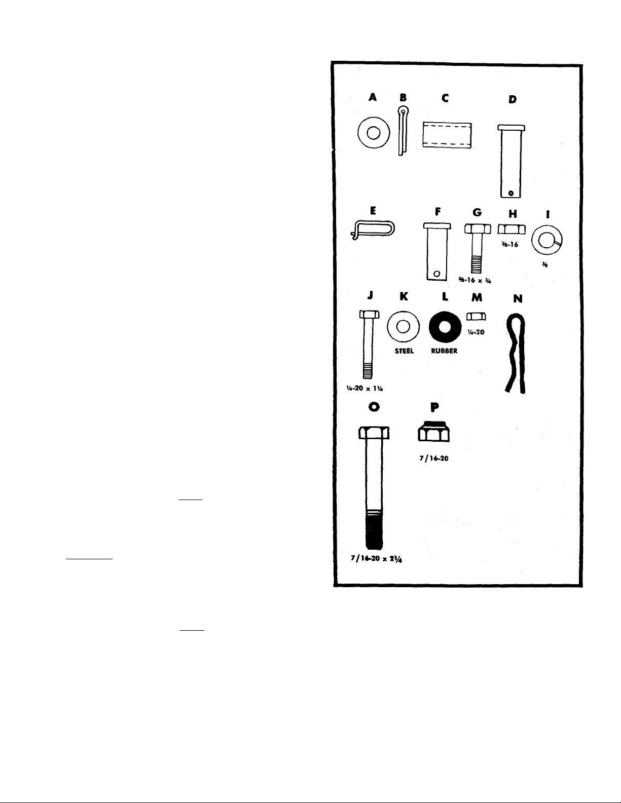
FIGURE 1. HARDWARE SUPPLIED
Wheel end Wheel Hanger Assembly
Refer to figure 2.
Step 1. Slide the axle through the wheel hanger.
Step 2. Place the washer A, spacer C, wheel and
washer A on each side of the axle and se
cure each with a cotterpin B as shown.
Page 3
WHEEL
HANGEI
FIGURE 2. WHEEL ASSEMBLY
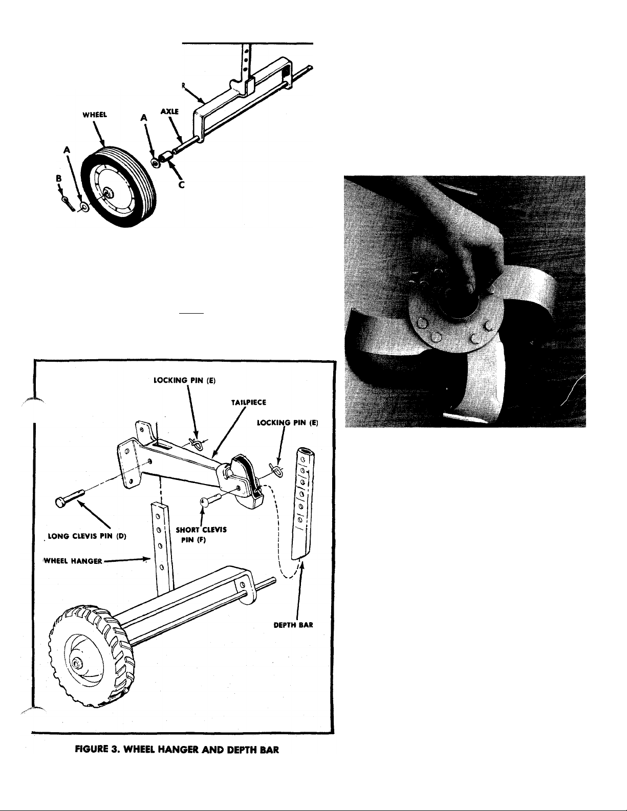
Step 3. Place the wheel hanger into the tailpiece and
secure with the long clevis pin (D) and locking
pin (E). See figure 3.
NOTE
For the initial set up, use the second
hole from the bottom on the wheel
hanger.
Depth Bar
Refer to figure 3.
Step 1. Attach the depth bar to the tailpiece with the
clevis pin F.
Step 2. Secure the clevis pin F with the locking pin E.
Dust Pad
Install the dust pads in each inner tine assembly. See
figure 4.
FIGURE 4. DUST PADS
Tine Assembly
Step 1. The inner tine assemblies are already assem
bled to the tiller.
Step 2. The outer tine assemblies are inverted on the
tine shaft for shipping purposes only, and
MUST be removed and turned around so that
the sharp edge of the tines enter the soil first.
Secure with bolt O and locknut P. See figure 5.
Page 4
ri-': '
FIGURE 5. OUTER TINE ASSEMBLY
NOTE
Be sure the tines are assembled so the
sharpened edge enters the soil first.
Handle Assembly
Refer to figure 6.
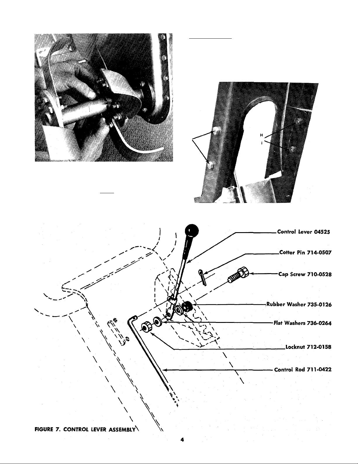
Step 1. Assemble the handle assembly to the handle
mounting brackets with 4 hex bolts G, lockwashers I and hex nuts H.
Step 2. Assemble grips to handle.
nOURE 6. HANDLE ASSEMBLY
CONTROL ASSEMBLY
Page 5
CONTROL ASSEMBLY (See figure 7.)
Throttle Control Assembly
Assemble control lever in box on handle panel as
shown. Be sure control lever is positioned with the
hole in the control rod mounting clevis up (or to
the rear).
2. Insert the "L" shaped end of control rod through
the lower opening of the box. Screw the threaded
end of the control rod into the ferrule on the vari
able speed control. It will extend approximately
3. Insert the "L" shaped end of the control rod into
the control lever and fasten with cotter pin.
4. Remove spark plug wire. Place control lever in neu
tral. Pull recoil starter rope several times. Tines
should not rotate. If tines rotate, adjust control rod
in ferrule until "NEUTRAL" is obtained.
5. Replace spark plug wire.
CAUTION
If the belt cover (Ref. No. 63 on page
12) is removed, you will not have any
neutral. This belt guard contains the
belt trapout meant for around the en
gine pulley. The control rod must be as
sembled exactly as noted above and as
shown in figure 7 or there will be no
neutral and the tiller tines will rotate
as long as the engine runs.
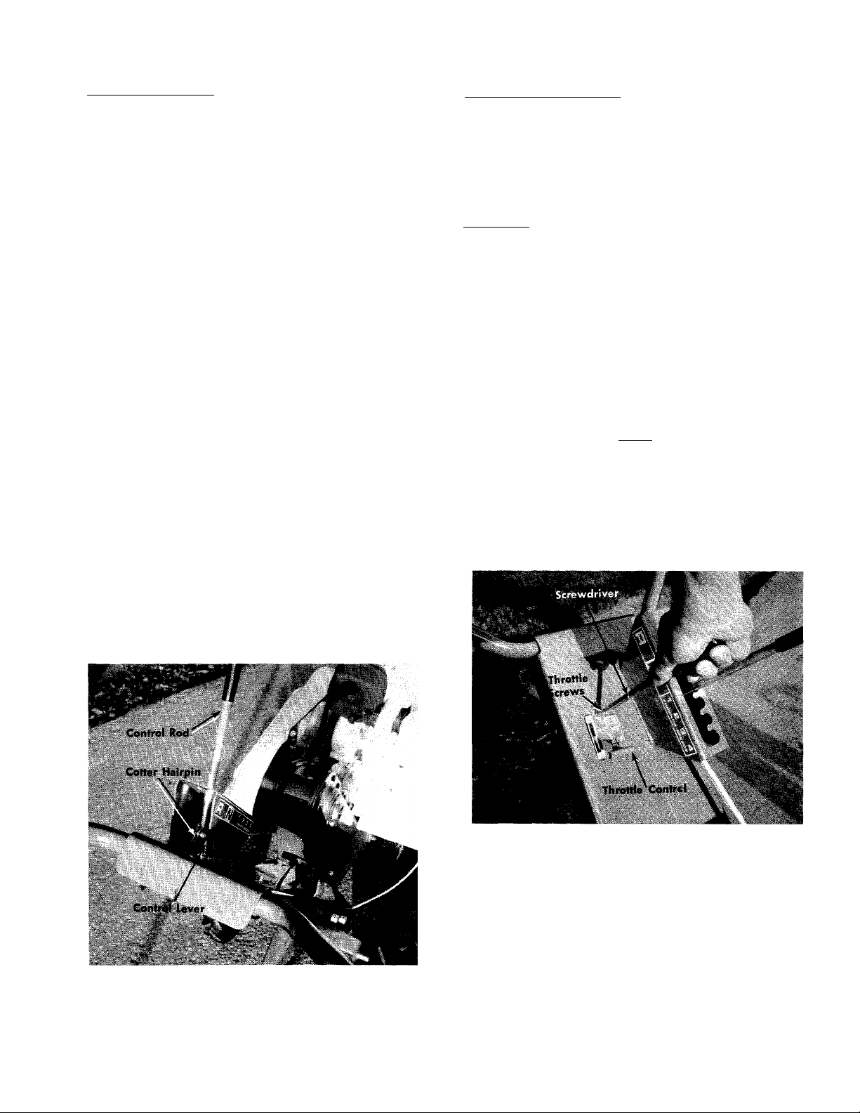
Step 1. Place throttle control in handle and assemble
to handle with the two throttle screws using
a screwdriver. See figure 8.
CONTROLS
The controls on your Rotary Tiller are the control lever,
throttle control and depth bar.
The Control Lever
The Control Lever is released from Neutral by moving
it to the right and allowing the spring tension to pull
the control lever into one of the four forward speeds.
See figure 9.
NOTE
Number 1 position is the slowest tine
rotation speed and number 4 is the
fastest.
Pulling the control lever slowly backwards into Re
verse position reverses the direction of tine rotation.
Reversing should be done at half throttle position.
FIGURE 8. THROmE CONTROL
FIGURE 9. CONTROLS
Page 6

The Throttle Control
The throttle control actuates the butterfly in the carbu
retor which controls the speed of the engine.
NOTE
Always check the throttle cable and
wire at the engine end for a tight con
nection.
To stop the engine, pull the throttle control all the way
back towards you. To start, push the throttle control all
the way forward. See figure 9.
The Depth Bar
The depth bar is used to prevent the tiller from running
on top of the ground instead of tilling. The deeper
you set the depth bar, the deeper you will till. Tilling
depth is from 0 to 8 inches. See figure 10.
WHEEL ADJUSTMENT
The wheel height can be adjusted by removing the
long clevis pin on the wheel hanger and raising or
lowering the setting. The higher the setting the deeper
the tilling depth. See figure 11.
NOTE
Pick a height that places the handles in
a comfortable position for the operator.
TILLING WIDTH ADJUSTMENT
The tilling width is adjustable from 12 inches to 40
inches with the use of the optional extension tines. The
standard tilling width with both the inner and outer
tines is 26 inches. By removing the outer tines you re
duce the tilling width to 12 inches.
FIGURE 11. WHEEL HEIGHT ADJUSTMENT
CHECKING OIL, GASOLINE AND CHAIN CASE
NOTE
When packaged for shipment the ma
chine contains no oil or gasoline. Before
starting the engine, oil must be added
to the engine crankcase and gasoline
to the tank. DO NOT mix oil with gaso
line.
a. Oil
With the tiller on level ground, remove the oil filler
plug from the engine and fill the crankcase with good
quality, SAE 30 type MS engine oil until it overflows.
The crankcase holds approximately 2% pints of oil.
Pour slowly to avoid air locks. Replace the oil filler
plug. See figure 18.
b. Gasoline
Remove the gas cap and fill the tank with FRESH REG
ULAR GRADE GASOLINE. If the gasoline has been in
a metal can for a long period, throw it away and use
fresh gasoline.
c. Chain Case Lubricant
The chain case is sealed and requires no further lubri
cation unless the chain case is disassembled for repair.
Page 7

Step 4. When the engine starts, gradually move the
throttle to the fast position. After engine
warms up (about 2 or 3 minutes) set throttle
at idle position.
Step 5. DO NOT OVERCHOKE ENGINE. Repeated
cranking with throttle at START position will
cause gasoline to flood the intake tube and the
engine. If, after 3 or 4 attempts, the engine
fails to start, place throttle in fast position,
crank the engine several times to clear out
the excess fuel; and then proceed with steps
2, 3 and 4.
STOPPING THE ENGINE
To stop the engine, pull the throttle control all the way
back to STOP position. See figure 9. When the throt
tle control is in the STOP position, a switch blade is
activated to short-circuit the spark plug.
Whenever the tiller is left unattended,
disconnect the spark plug lead and place
the throttle control in the STOP position.
AIR FILTER
The air filter is pre-serviced at the factory and requires
no additional servicing before the initial use of the
tiller, however, the air cleaner should be serviced per
iodically as stated on page 8.
STARTING THE ENGINE
Step 1. With the tiller set on level ground, set the
control lever in NEUTRAL.
Step 2. Set the choke in the START.
Step 3. As illustrated in figure 13, grasp the recoil
starter handle, pull out sharply, and hold it
in the out position. (Do not let cord snap back.)
STOPPING THE TINES
Pull the control lever into the NEUTRAL position. The
tines will not rotate. See figure 9.
OPERATING THE TILLER
Typical operation of the tiller is as follows:
Step 1. Set the clutch control to NEUTRAL.
Step 2. Start the engine.
NOTE
To move the tiller to the work area,
keep the depth bar in the highest posi
tion. With the throttle in the SLOW posi
tion, slowly engage the control lever
into the number 1 position and the tiller
will walk to the work area without dig
ging into the ground.
Step 3. With the clutch control in NEUTRAL, set the
depth bar in one of the lower settings.
NOTE
When several passes must be made
over the same area, lower the depth bar
each time a pass is made.
Step 4. Set the throttle control to fast. (See page 5.)
FIGURE 13. RECOIL STARTER
NOTE
The cord should NOT be pulled out
more than about two feet. If engine
fails to start, allow the cord to wind
back into the housing, then pull out
sharply again. Refer to Step 5.
Step 5. Slowly engage the clutch control to the num
ber 1 position and the tines will begin rotat
ing. Number 4 position will give the maxi
mum tine speed. Tilling the ground for the
first time should be done in the number 1 or 2
position. To pulverize tne soil after it has been
tilled, move the control lever to the number 3
or 4 position.
Page 8

NOTE
This tiller is equipped with a variable
speed pulley making it necessary for
the engine to be running to move
the control lever into the faster speeds.
A downward pressure on the handles
will increase working depth and re
duce the forward speed. An upward
pressure on the handles will reduce the
working depth and increase the for
ward speed. The type of soil and work
ing conditions will determine the actual
setting of the depth bar and the handle
pressure required.
If the tines stop rotating or the belt
slips, stop the engine and examine the
tine area for a rock or some object that
may be jamming the tines and prevent
them from turning. Reversing the tiller
will usually free the object.
Step 2. After the oil has been drained completely
from the crankcase, replace the drain plug and
tighten.
Step 3. With the tiller on level ground, remove the
oil filler plug (See figure 16). Fill the crankcase
until the oil overflows from the oil fill hole.
Fill slowly to avoid air locks. The crankcase
should hold approximately 2% pints of SAÉ
30 type MS engine oil. Replace the oil filler
plug.
CHAIN CASE LUBRICATION
The chain is permanently lubricated and requires no
further lubrication unless the case is disassembled for
repair.
If the case is disassembled, clean the chain with kero
sene, allow it to dry and work a high temperature
grease, such as Lubriplate No. 310 into the chain.
NOTE
If the tines tend to bounce instead of
cutting into the soil, one or more sets
of tines may be on backwards. The
cutting edge of the tines should enter
the soil first.
Step 6. To reverse the direction of rotation of the
tines, pull the control lever into the reverse
position. The control lever must be held in
reverse. See figure 9.
b. Oil Change
To avoid spilling gasoline on your lawn or driveway,
plan to change the oil when the gasoline tank and car
buretor are empty.
After the first two hours of operating a new engine,
drain the oil from the crankcase while the engine is
still hot and refill the crankcase with new oil; there
after change the oil after every 25 hours of operation.
This procedure ensures for minimum wear of engine
parts and provides for virtually trouble-free operation.
To change the oil, proceed as follows:
Step 1. With the machine on level ground, place a
suitable metal container under the oil drain
plug, then remove the drain plug. See figure
12.
NOTE
A 4 oz. container of Lubriplate No. 310
is available under part number 727-0136.
CHAIN ADJUSTMENT
No chain adjustment is necessary.
AIR FILTER
Under normal operating conditions, the air cleaner,
located on top of the carburetor, must be serviced
after every ten hours of use. Under extremely dusty
operating conditions, the air cleaner must be serviced
after every hour of operation. See figure 15.
Step 1. Remove the wing nut and cover.
Step 2. Remove the paper element from the support
base.
Step 3. To clean, tap the paper element (either top or
bottom) on a flat surface or wash in a nonsudsing detergent and flush from the inside
until the water is clear. After washing, air dry
thoroughly before using.
FIGURE 15. AIR CLEANER
Page 9

CLEANING ENGINE AND TINE AREA
Any fuel or oil spilled on the tiller should be wiped
off promptly. Dirt, leaves and other debris must not be
left to accumulate around the cooling fins or the engine
or on any part of the tiller. Clean the under side of the
tine shield after each use. The dirt washes off the tine
easier if washed off immediately instead of after it
dries.
The blower housing is held in place with three screws.
One on the top of the engine and two on the bottom.
See figure 16.
BELTS
Check that belts are free of oil or dirt. Wipe the belts
periodically with a clean rag.
SPARK PLUG
The spark plug gap should be cleaned and reset to a
0.030-inch clearance every 25 hours of engine opera
tion (See figure 17). Spark plug replacement is rec
ommended at the start of each tiller season; check en
gine parts list for correct plug type.
FIGURE 18. GASOLINE FILTER AND SHUT-OFF
BELT ADJUSTMENT
How to adjust:
Step 1. Remove the belt cover as shown in figure 18.
Step 2. Start the engine according to the instructions
on page 7.
Step 3. Tip the tiller back on its wheels until the tines
clear the ground.
Step 4. Move the control lever into number four posi
tion.
NOTE
The inside belt should move to the out
side edge of the variable speed pully
so the top of the belt is almost flush
with the pulley. See figure 19.
Step 5. If adjustment is necessary, adjust the control
rod by screwing it in or out of the ferrule as
necessary. See figure 20.
GASOLINE FILTER AND SHUT-OFF VALVE
Refer to figure 18.
Step 1. Close the shut-off valve.
Step 2. Loosen the thumb screw below the bowl.
Step 3. Remove and clean the screen.
Step 4. Open the shut-off valve to see if gasoline
flows freely from the gasoline tank.
Step 5. Clean the bowl and screen. Use alcohol or
acetone to clean the parts if you find a gum
my, varnish-like substance in the bowl.
Step 6. Reassemble.
Step 7. Open the shut-off valve.
nirew Puii-y
Com
Ferrule^
FIGURE 19. DRIVE SYSTEM
CAUTION
With the belt cover removed your unit
will not have a neutral. The tines will
always turn. You must hold the tines off
the ground either by having someone
else hold the handle down or by placing
the handles under something solid such
as a work bench while you start the en
gine.
Page 10

VARIABLE SPE
PULLEY
Rear Beh
BEIT SHOUIO BE IN THIS
POSITION WITH CONTROL
LEVER IN NO. 4 POSITION
FIGURE 20. VARIABLE SPEED PULLEY
BELT REPLACEMENT
CAUTION
Be careful not to pinch your fingers betv/een the pulley and belt.
Step 1. Remove the belt cover so the belts are ex
posed as shown in figure 19.
CHAIN CAS’E Step 2. Put the depth bar on the wheel hanger and
place the tip of the depth bar under the var
iable speed pulley bracket as shown in figure
21.
Step 3. Place your foot on the rear of the depth bar
and apply pressure. The belts will go slack.
Step 4. Remove the REAR belt first and allow it to
form a loop around the variable speed pulley.
Step 5. Slide the center section of the variable speed
pulley towards the engine. See figure 19.
CENTER SECTION Step 6. Remove the FORWARD belt from the engine
pulley and the variable speed pulley.
NOTE
By following this order of bfelt removal,
it is not necessary to remove the belt
guard on the variable speed pulley.
Step 7. Remove the rear belt from the variable speed
pulley.
Step 8. Reassemble with the new belts.
FIGURE 21. BELT REMOVAL
CARBURETOR ADJUSTMENT See figure 22.
Minor carburetor adjustment may be required to com
pensate for differences in fuel, temperature, altitude
and load. To adjust:
Step 1. Turn needle valve clockwise until it just closes.
CAUTION
Valve may be damaged by turning too
far.
Step 2. Open needle valve 114 turns counterclockwise.
Step 3. Close the idle valve in the same manner and
open 114 turns.
4. Start the engine.
Step
5. Turn the needle valve in until the engine
Step
misses,
6. Then turn it out past smooth operating point
Step
until the engine runs unevenly.
Step 7. Turn the needle valve mid-point between the
two settings so the engine runs smoothly.
Step 8. Set the throttle in the idle (slow) position and
set the idle speed adjusting screw until a fast
idle is obtained.
St^ 9. With the throttle stilLin the idle position, turn
the idle valve in and out until the engine idles
smoothly.
10
Page 11

ADJUSTING THE CARBURETOR CHOKE
Proper choke and stop switch operation is dependent
upon proper adjustment of remote controls on the
powered equipment.
To Check the Operation of the Choke:
Step 1. Remove the air cleaner.
Step 2. Push the throttle control all the way forward
to the START position. See figure 10. The choke
should be closed.
Step 3. The engine should shut off when the throttle
control is ail the way back. (STOP position.)
To adjust:
Place remote control lever on equipment in fast (high
speed) position. Loosen control casing clamp screw
"B". Move control casing "A" and wire until lever "D"
touches choke operating link at "C". Tighten casing
clamp screw 'B". Replace air cleaner. See figure 24.
OFF-SEASON STORAGE
If the machine is to be inoperative for a period longer
than 30 days, the following precautions are recom
mended:
Step 1. Working outdoors, drain all fuel from the
fuel tank. Use a clean dry cloth to absorb the
small amount of fuel remaining in the tank,
then run the engine until all fuel in carburetor
is exhausted.
WARNING
L;
DO NOT DRAIN FUEL WHILE SMOKING,
OR IF NEAR AN OPEN FIRE.
Step 2. Drain all the oil from the crankcase (this
should be done after the engine has been op
erated and is still warm) and refill the crank
case with clean new oil.
Step 3. Disconnect the spark plug wire and remove
the spark plug from the cylinder. Pour about
six drops of engine oil into the cylinder, and
then pull the recoil starter several times to
spread the oil on the cylinder wall. Replace
the spark plug, but DO NOT connect the wire.
Step 4. Clean the engine and the entire tiller thor
oughly.
Step 5. Wipe tines with oiled rag to prevent rust.
FIGURE 23. CHOKE ADJUSTMENT
11
Page 12

215-390A
215-395A
IF YOU WRITE TO US ABOUT THIS ARTICLE
OR IF YOU ORDER REPLACEMENT PARTS AL
WAYS MENTION THIS MODEL & SERIAL NO
MODEL
12
Page 13

PARTS LIST FOR MODELS 215-390A AND 215-395A
REF.
PART
NO.
20
21
22
23
24
25
26
27
28
29
30
31
32
NO.
1
2
710-0380
710-0176
3
4
5
6
7 720-0143
8
9 711-0422
10 710-0528
11
12
13
14
15
16
17
18
19
04524
710-0376
04494
710-0253
714-0507
712-0158
01166
746-0242
04625-463
04525
736-0264
735-0126
736-0264
736-0217
712-0798
04506-463
710-0152
736-0217
04505-463
04507-463
732-0194
736-0217
710-0152
732-0194
04668-463
711-0231
04527-463
COLOR
CODE
DESCRIPTION
Engine
Hex Hd. Cap Scr. 5/16-18 x
1%" Lg. (215-395A)
Hex Hd. Cap Scr. 5/16-18 x
2%" Lg. (215-390A)
Tine Shield
Hex Hd. Cap Scr. 5/16-18
X 1" Lg.*
Engine Spacer Ass'y. (215-390A)
Only)
Hex Hd. Cap Scr, %-16 x 1.00"
Lg.*
Grip
Cotter Pin 3/32 X %" Lg.*
Control Rod
Hex Hd. Cap Scr. 5/16-18 x
VA" Lg.*
Hex Centerlock Nut 5/16-18
Thd.*
Grip
Throttle Control Ass'y. Comp.
Handle Ass'y.
Control Lever Ass'y.
Flat Washer*
Rubber Washer*
Flat Washer*
L-Washer % Scr.*
Hex Nut %-16 Thd.*
Handle Mtg. Brkt.
Hex Hd. Cap Scr. %-24 x 1"
Lg.*
L-Washer % Scr.*
Handle Mtg. Brkt.
Tail Piece
Spring Pin
L-Wash. %" Scr. H.D.
Hex Hd. Cap Scr. %-24 x 1"
Lg.*
Spring Pin
Depth Bar
Clevis Pin
Wheel Hanger Brkt. Ass'y.
NEW
PART
I
REF.
NO.
49
51
52
53
54
55
56
57
58
59
60
61
62
63
64
65
66
67
68
69
N
70
71
PART
COLOR
NO.
CODE
33
711-0510 Clevis Pin
34
35
36
37
38
39
40 04474-463
41 04511-463 Inner Tine Adapter
42 721-0124
43
44
45 04511-463
46
47
48
50
04451
711-0313
734-0575
736-0108
714-0115
712-0236
721-0125
742-0113
742-011®
04474-463
710-0191 Hex Hd. Cap Scr. %-24 x 1.25"
736-0217
712-0241
710-0483
736-0119
712-0158
04519-463
712-0158
736-0119
04519-463
710-0258
710-0252
04516
736-0329
712-0287
04537
710-0121
736-0921
04523
712-0287
748-0147
710-0180
736-0217
710-0227
Rear Axle
Spacer
Wheel Ass'y. Comp.
Flat Washer*
Cotter Pin Va Dia. x 1" Lg.*
Hex Elastic Stop Nut 7/16-20
Outer Tine Adapter
Dust Pad
Dust Pad
Tine—lA.H
inner Tjhe Adapter
Tine—1^.//
Outer Tine Adapter
L-Washer for % Scr.*
Hex Nut %-24 Thd.*
Hex Hd. Cap Scr. 7/16-20 x
L-Washer 5/16 Scr.*
Hex Center L-Nut 5/16-18 Thd.
Engine Mtg. Brkt.
Hex Center L-Nut 5/16-18 Thd.
L-Washer 5/16 Scr.*
Engine Mtg. Brkt.
Hex Hd. Cap Scr. V4-20 x %" Lg
Hex Hd. Cap Scr. ’A-20 x %" Lg
Belt Guard
L-Washer Va" Scr.*
Hex Nut'/4-20 Thd.*
Belt Trap Ass'y.
Hex Hd. Cap Scr. ’/2-20 x %" Lg
L-Washer '/2" Scr.*
Variable Speed Guiding Brkt.
Hex Nut Va-20 Thd.*
Bushing
Hex Scr. %-24 x .75" Lg.*
L-Wash. %" Scr. H.D.
Hex Wash. Hd. AB-Tapp Scr.
DESCRIPTION
Thd.
2’/4" Lg.*
#8 X .38" Lg.*
NEW
PART
*
*
*For faster service obtain standard nuts, bolts, and washers locally. If these items cannot be obtained lo
cally, order by part number and size as shown on parts list.
(463—^Top Flite Red)
When ordering parts, if color or finish is important, use the appropriate color code
shown at left. (e.g. Top Flite Red finish,04625(463).)
13
Page 14

215-390A
215-395A
IF YOU WRITE TO US ABOUT THIS ARTICLE
OR IF YOU ORDER REPLACEMENT PARTS AL
WAYS MENTION THIS MODEL & SERIAL NO
MODEL
TINE ASSEMBLIES COMPLETE
Inner Tine Assembly—L.H.—Complete 04541
Inner Tine Assembly—R.H.—Complete 04542
Outer Tine Assembly—L.H.—Complete 04095
Outer Tine Assembly—R.H.—Complete 04096
53 52 51 50 49 4d 47 46 4 5 44 43 42 41
14
Page 15

PARTS LIST FOR MODELS 215-390A AND 215-395A
PART COLOR NEW
REF.
NO.
1
2
715-0124
3
748-0181
4
741-0139 Ball Brg. .50 I.D. x 1.38 O.D.
5
750-0144
6
750-0146
7
741-0139
8
748-0177
9
10
11
12
735-0127
13
14 736-0300
15
741-0155
16 05034 Bearing Housing 1% Dia.
17 736-0329 L-Washer 'A" Scr.*
18
710-0258 Hex Hd. Cap Scr. '/4-20 x %" Lg.*
19
714-0136
20
21
22
754-0158
23
712-0461
24
25
756-0167
26
712-0221
27
736-0204
28
736-0329
29
710-0230
30
712-0116
31
712-0116
32
736-0300
33
711-0392
34
711-0422
35
714-0115
36
712-0116
37
735-0127
38
736-0300
39
71 n.n1t R
40
736-0119
41
712-0461
42
710-0152
43 736-0217
44
45
714-0133
714-0118
NO.
10844
04523
04517-463
04501-463
11021-463
05080
04515
04510-463
07386
CODE
Sheave Half with 3 Holes 46 10843
Spring Pin Spiral 5/32 Dia. x
Movable Sheave 390A5 H.P. Only)
Steel Tubing
Spacer .520 I.D. x .692 O.D.
Ball Bearing .50 I.D. x 1.38 O.D. 50 710-0380 Hex Hd. Cap Scr. 5/16-18 x
Sheave Half 1%" Lg.*
Variable Speed Guiding Brkt.
Variable Speed Brkt. Ass'y.
Housing Ass'y.—l-.H. Side
Eccentric Link
Rubber Washer
Flat Washer
Ball Brg. % I.D. X 1% O.D.
Hi Pro Key #505
Friction Wheel Ass'y.
Friction Disc
"V"-Belt 21/32 X 35" Lg. Spec.
Hex Jam Nut '/2-13 Thd.
Variable Speed Belt Guard
8" O.D. x % Split Pulley
Hex Elastic Stop Nut %-18 Thd.
Flat Washer
L-Washer 'A" Scr.*
Hex Hd. Cap Scr. '^-28 x '/2" Lg.
Hex Elastic Stop Nut %-24 Thd
Hex Elastic Stop Nut %-24 The
Flat Washer
Ferrule
Control Rod
Cotter Pin Vs Dia. x 1" Lg.*
Hex Elastic Stop Nut %-24 Thd.
Rubber Washer
FI.-Wash.
Hex Hd. Cap Scr. 5/16-18 x %"
L-Washer 5/16 Scr.*
Hex Jam Nut '/2-13 Thd.
Hex Hd. Cap Scr. %-24 x 1"
Spring L-Wash. % Scr. H.D.
Flat Washer
Sq. Key3/16xl'/2"Lg.* (215-
Sq. Key '/4 X I'A" Lg.* (215-395A)
DESCRIPTION PART
.62“ Lg. 48
Lg. l>]-\Si
Lg. H.T.
390A)
REF.
PART COLOR
NO.
NO.
47
754-0157
49 738-0138
51 11022
52
711-0509
53
732-0232 Variable Drive Spring
54
712-0158
55
736-0119
56
57
721-0117
58
748-0194
59
712-0287
60
736-0329
61
721-0119
62
711-0506
63
713-0150
64 717-0189
65
715-0125
66
710-0258
67 04530-463
68
710-0118
69
736-0119
70
736-0195
71
72
711-0504
73
748-0855
74
75
717-0188
76
715-0120
77
750-0118
78
/y
/ i O-U1^y
80
711-0505
81
748-0855
82
726-0106
83
748-0180
84
750-0166
85
86
730-0158
CODE
04532
04531
04530-463
04503-463
04529
—
04521
Variable Speed Pulley Ass'y.
"V''-Belt21/32 x28" Lg
Engine Pulley Ass'y. (For 215Engine Pulley Ass'y. (For 215-
395A8 H.P. Only)
Shoulder Bolt—Special
Spring Bracket
Spring Insert
Hex Center L-Nut 5/16-18 Thd.*
L-Washer 5/16 Scr.*
Cast Bearing Housing Ass'y.
Oil Seal VA" I.D. x 1%" O.D.
Flange Brg. VA" I.D. x 1%" O.D.
Hex Center L-Nut '^-20 Thd.*
L-Washer '/4" Scr.*
Gasket
Tine Shaft
24-2 Teeth Sprocket '/2'' Pitch
Spirol Pin % Dia. X 2" Lg, H.D.
Hex Hd. Cap Scr. '/4-20 x %" Lg.
Cast Bearing Housing Ass'y.
Hex Hd. Cap Scr. 5/16-18 x
%" Lg.*
L-Washer 5/16 Scr.*
Flat Washer
Housing Ass'y.—R.H. Side
Sprocket Shaft
Flange Bearing
Double Sprocket Ass'y.
11-2 Teeth Sprocket % Pitch
Spirol Pin 3/16 Dia. X 1" Lg. H.D.
Spacer
Part of Ref. No. 74
Pulley Shaft
Flange Bearing
Push Nut
Pivot Slide
Spacer
Link Brkt. Ass'y.
L-Wash. %" Scr.*
DESCRIPTION
________
NEW
PART
Spec.
.|e
i-H'i
- ■
1
1
*For faster service obtain standard nuts, bolts, and washers locally. If these items cannot be obtained lo
cally, order by part number and size as shown on parts list.
(463—Top Flite Red)
When ordering parts, if color or finish is important, use the appropriate color code
shown at left. (e.g. Top Flite Red finish,04625(463).)
15
Page 16

PARTS INFORMATION
DEFECTIVE OR MISSING PARTS must be reported
to the factory immediately. Such claims must include
your model number and date of purchase.
POWER EQUIPMENT PARTS AND SERVICE
Parts and service for all MTD manufactured power
equipment are available through the authorized serv
ice firms listed below. All orders should specify the
model number of your unit, parts numbers, descrip
tion of parts and the quantity of each part required.
A 1 Engine * Mower Co.
327 East 9th Street
Salt Lake City, Utah 84102
Auto Electric A Carburetor Co.
2i25 4th Avenue, S.
P. O. Box 1948
Birmingham, Alabama 35233
Automotive Equipment Service Co.
3117 Holmes Street
Kansas City, Missouri 54109
Bailey's Rebuild Inc.
1325 E. Madison Street
Seattle Washington 98102
Blecicrie, Inc.
7900 Lorain Avenue
Cleveland, Ohio 44102
Brown Equipment Distributor Inc.
? 10 SeMh Street
Corydon, Indiana 47112
Bullard Supply
2409 Commerce Street
Houston, Texas 77003
Catto A Putty, Inc.
P. O. Box 2408
510 Soledad Street
San Antonio, Texas 78205
Center Supply Company
6867 New Hampshire Avenue
Takoma Park, Maryland 20012
Dixie Sales Company
P. O. Box 1408
327 Battleground Avenue
Greensboro, North Carolina 27402
East Point Cycle A Key Shop
1617 Whiteway
East Point, Georgia 30044
\
Gamble Distributors
West End Avenue
Carthage, New York 13619
Garden Equipment Co., Inc.
6600 Cherry Avenue
Long Beach, California 90805
Gardenville Supply, Inc.
Pipersville, Pennsylvania 18947
Henry W. O'Neil & Assoc., Inc.
410 North Goodman Street
Rochester, New York 14609
Henzier, Inc.
2015 Lemay Ferry Road
St. Louis, Missouri 63125
Kenton Supply
8216 North Denver Avenue
Portland, Oregon 97217
KImber's Inc.
115 W. Geddes St.
Syracuse, New York 13204
Marr Brothers
423 E. Jefferson
Dallas, Texas 75203
McClure Lawn A Garden Supply
1114 Lexington Avenue
Mansfield, Ohio 44907
Memphis Cycle A Supply Co.
421 Monroe Avenue
Memphis Tennessee 38103
Morton B. Collins Co.
300 Birnie Avenue
Springfield, Massachusetts 01107
Moz-AII of Florida, Inc.
365 Greco Avenue
Coral Gables, Florida 33146
National Central,
687 Seville Rd.
Wadsworth, Ohio 44281
BRIGGS & STRATTON, TECUMSEH AND PEERLESS
PARTS AND SERVICE
Briggs & Stratton, Tecumseh and Peerless parts and
service should be handled by your nearest authorized
engine service firm. Check the yellow pages of your
telephone directory under the listing Engines —
Gasoline, Briggs & Stratton or Tecumseh Lauson —
Power Products.
Parts A Sales Inc.
2101 Industrial Pkwy.
Elkhart, Indiana 46514
Power Equipment Distributor
36463 So. Gratiot Avenue
Mt. Clemens, Michigan 48043
Power Lawn A Garden Equip. Co.
2551-2571 J. F. Kennedy Road
Dubuque, Iowa 52001
Radco Distributors
2403 Market Street
P. O. Box 3216
Jacksonville, Florida 32206
Raub Supply Company
James A Mulberry Sts.
Lancaster, Pennsylvania 17604
Richmond Battery A Ignition
P, O. Box 25369 - 957 Myers St.
Richmond, Virginia 23260
R. P. W., Inc.
623 S. 16th Street
Omaha, Nebraska 68102
Smith Hardware Company
515 N. George Street
Goldsboro, North Carolina 27530
South Denver Lawn Equip. Co,
527 West Evans
Denver, Colorado 80223
Suhren Engine
8330 Earhart Blvd.
New Orleans, Louisiana 70118
Sutton's LaWn Mower Shop
Route 4, Box 343
North Little Rock, Arkansas 72117
Warner Equipment
7520 Lyndale Avenue, So.
Minneapolis, Minnesota 55423
Woodson Sales A Service
1702 North Sylvania
Ft. Worth, Texas 76111
♦
♦
WARRANTY PARTS AND SERVICE POLICY
The purpose of warranty is to protect the customer from defects in workmanship and materials,
t
defects which are NOT detected at the time of manufacture. It does not provide for the unlimited
and unrestricted replacement of parts. Use and maintenance are the responsibility of the cus
t
♦
♦
♦
♦
♦
♦
♦
♦
♦
♦
t
tomer. The manufacturer cannot assume responsibility for conditions over which it has no
control. Simply put, if it's the manufacturer's fault, it's the manufacturer's responsibility; if
it's the customer's fault, it's the customer's responsibility.
CLAIMS AGAINST THE MANUFACTURER'S
WARRANTY INCLUDES
1. Replacement of Missing Parts on new equip
ment.
2. Replacement of Defective Parts within the
warranty period.
3. Repair of Defects within the warranty
period.
All claims MUST be substantiated with the
following information:
1. Model Number of unit involved.
2. Date unit was purchased or first put into
service.
3. Date of failure.
4. Nature of failure.
 Loading...