

Page 1
Owner's Operating
Service Instruction
lOtfc
Manual
ASSEMBLY OPERATION REPAIR PARTS
Model Nos.
215-370A
215-375A
rrrrrrrrrsTrrryrrrrrrrrrrrr^^
WARRANTY
For one year from date of purchase, MTD Products Inc will replace for the original purchaser, free
of charge, F.O.B. factory or authorized service firm, any part or parts found to be defective in material
or workmanship. Alt transportation charges on parts submitted for replacement under this warranty
must be paid by the purchaser. This warranty does not include replacement of parts which become
inoperative through misuse, excessive use, accident, neglect, improper maintenance or alterations by
unauthorized persons. This warranty does not include the engine, motor, battery, battery charger or any
component parts thereof. For service on these units, refer to the applicable manufacturer's warranty.
The above warranty will apply only to the original owner and will be effective only if the warranty
card has been properly processed. It will not apply where the unit has been used commercially.
Warranty service is available through your local authorized service dealer or distributor. UNDER
NO CIRCUMSTANCES WILL THE RETURN OF A COMPLETE UNIT BE ACCEPTED BY THE
FACTORY UNLESS PRIOR WRITTEN PERMISSION HAS BEEN EXTENDED.
MTD PRODUCTS INC
PRINTED IN U.S.A. FORM NO. 770-5634
• 5389 WEST 130th STREET . P. 0. BOX 2741 CLEVELAND OHIO 44111
Page 2
1. Your tiller is a precision piece of power equipment.
Exercise extreme caution at all times.
2. Do not attempt to start engine with the clutch con
trol in the engaged or FORWARD position.
3. Stand clear of tines when starting engine. Never
stand in front of, or work on tines while the en
gine is running.
4. NEVER place hands or feet in the vicinity of the
tines while the engine is running.
5. Always stop engine when tiller is not in actual use.
6. Always disconnect spark plug wire during repairs
or refueling operations.
7. Do not fill gas tank while engine is running. Do not
spill gasoline on hot engine.
Your rotary tiller is designed to take the work out of
gardening and other related chores. It can be used
for seed bed preparation, tilling, cultivating, furrow
ing, composting and mulching. Like any other piece
of power equipment, it requires a certain amount of
care and maintenance. In return for this, it will give
a maximum of service and efficiency. Read these in
structions carefully before assembling or operating
your tiller. Through proper care and operation, you
will obtain long, efficient service and trouble-free
operation.
NOTE
The engine is shipped without oil in
the crankcase. See engine manual for
correct type and amount.
ASSEMBLY
Your rotary tiller is shipped complete in a single ca^
ton. The outer tines, wheels, handle, controls, depti
bar and tailpiece are to be assembled. This is done ir
the manner described below.
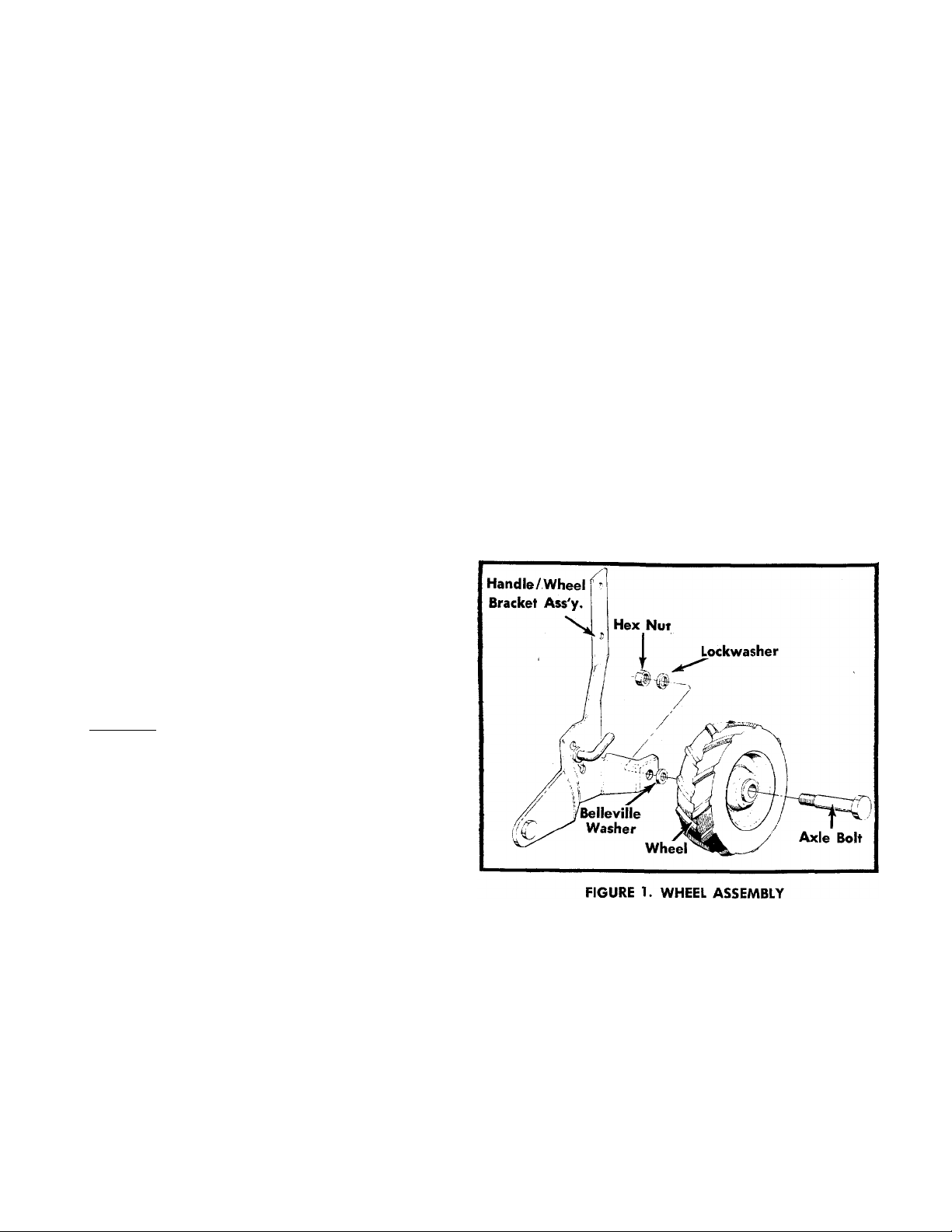
WHEELS
Insert axle bolt into wheel place Belleville washer on
threaded part of axle bolt. Crown of washer should be
positioned towards the wheel. Insert axle bolt in wheel
mounting hole of handle/wheel bracket assembly and
fasten with lockwasher and hex nut. See figure 1.
TINE ASSEMBLY
Step 1. The inner tine assemblies are already assem
bled to the tiller.
Step 2. The outer tine assemblies are inverted on the
Step 3. Remove the outer tine assembly and turn
tine shaft and MUST be removed and turned
around.
around so that the sharp edge of the tines
enter the soil first. Secure with bolt and lock
nut. See page 14.
Page 3
HANDLE ASSEMBLY
CONTROL ROD
Assemble the handle to the bracket with four cap
screws, washers and hex nuts. See figure 2.
Hex Nuts and Lockwashers
Hex Cap Sere'
FIGURE 2. HANDLE ASSEMBLY
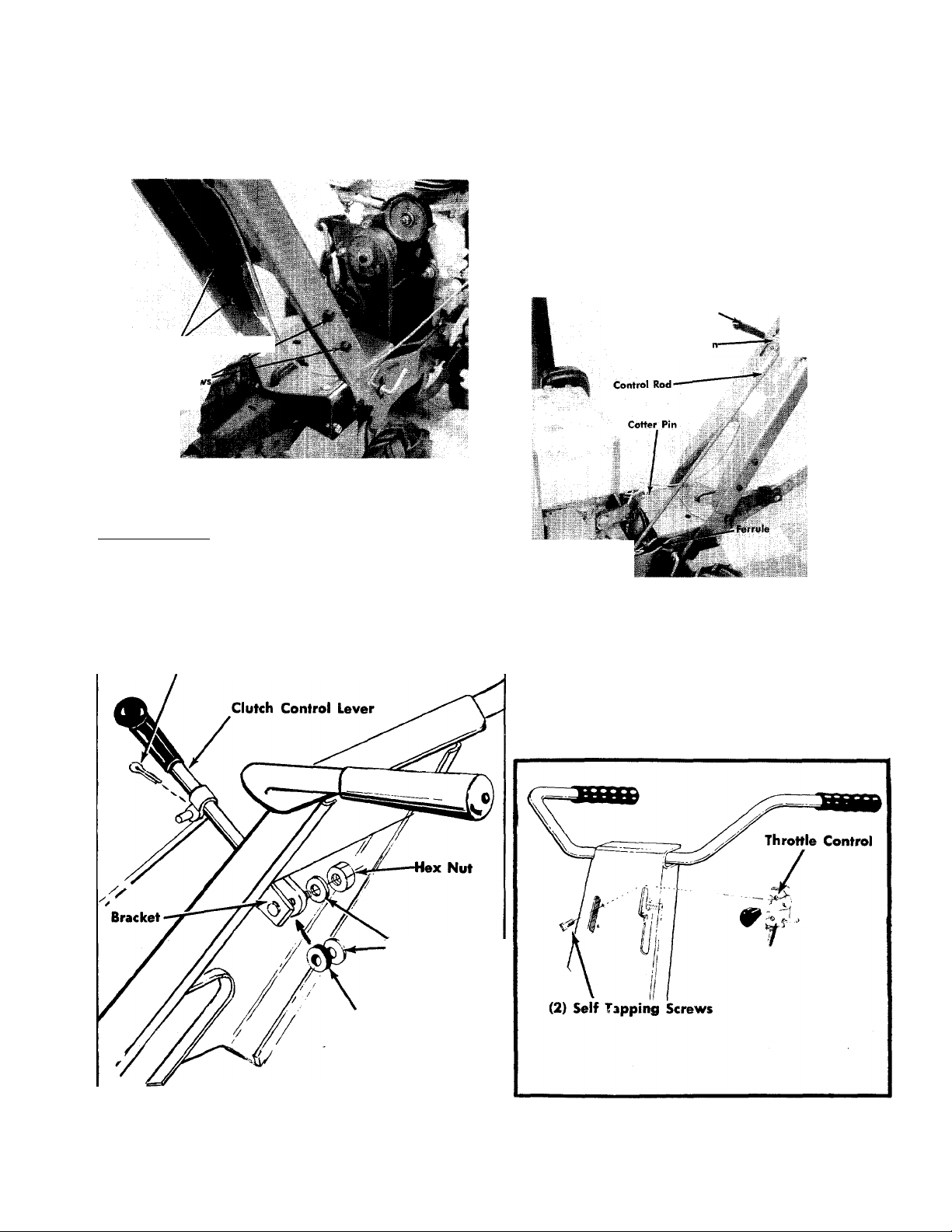
CLUTCH CONTROL
Place the clutch control lever through the handle pan
el and attach it to the bracket using a screw and hex
nut with two metal washers and a rubber washer
between the bracket and clutch control as shown in
figure 3.
Cotter Pin
Place the clutch control lever in neutral as shown in
figure 4. Screw the ferrule onto the control rod so that
approximately
the ferrule. Assemble the ferrule to the pivot idler
bracket and secure with a cotter pin.
Adjust the ferrule location on the control rod so both
the forward and reverse belts are slack with the clutch
control lever in the NEUTRAL position. Secure with a
cotter pin.
Va inch of threads are showing below
Clutch Control Lever
Cotter Pi
2
f
FIGURE 4. CONTROL ROD
THROTTLE
Assemble throttle control as shown in figure 5.
Flat Washers
Rubber Washer
FIGURE 3. CLUTCH CONTROL FIGURE 5. THROTTLE CONTROL
Page 4
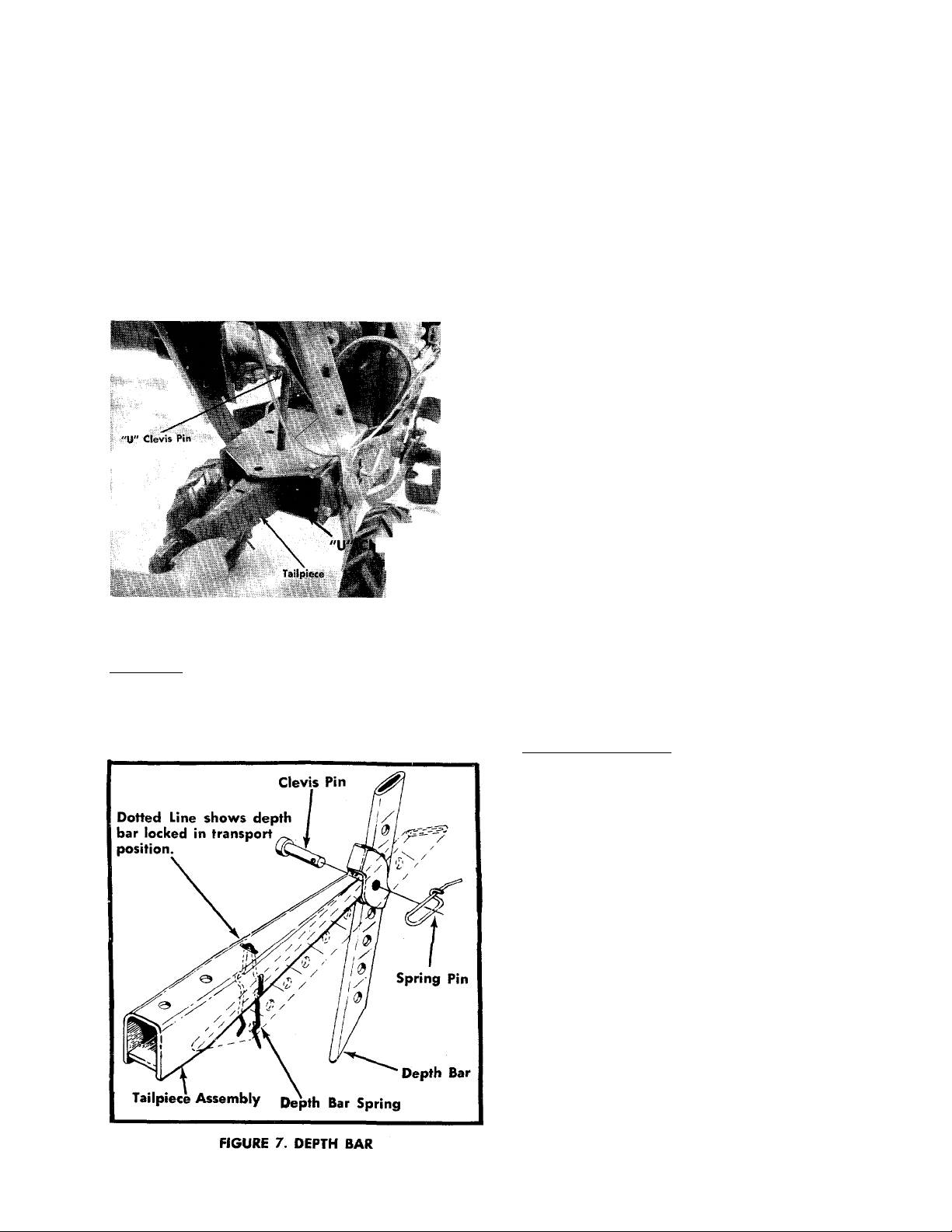
TAILPIECE
CHECK LIST BEFORE OPERATION
Attach the tailpiece to tiller with "U" clevis pin and
secure with spring pin. See figure 7.
NOTE
The "U" channel bracket assembly has
been assembled loose so that the tail
piece can be easily assembled to the
unit. After assembly of tail piece tighten
nuts and bolts tightly. See figure 6.
annel Bracket
fembly
FIGURE 6. TAILPIECE
DEPTH BAR
Attach the depth bar to the tailpiece with a clevis
pin and secure with the spring pin. See figure 8,
1. Remove spark plug wire from spark plug and '
ground. Check tiller tines for proper installatior
With throttle control lever set on STOP position ano
the clutch control handle set in FORWARD position,
slowly crank engine to determine direction of tine
rotation. Be sure all tines are mounted so the sharp
ened edges enter the soil first.
2. Place the clutch control lever in the NEUTRAL po
sition. Slowly crank engine. The tines should
not rotate. If they do, readjust control rod.
3. Check all nuts and bolts for correct tightness. This is
especially important during the initial operation
period. Make the same check periodically there
after.
4. Check throttle control for proper setting. Move
throttle control knob to STOP position. Move lever,
to which control wire is fastened at engine, to
CLOSE position and retighten screw to secure throt
tle control wire assembly.
5. Check gear case for proper lubricant level. With til
ler on a level surface, lubricant level should be up
to the front pipe plug opening. This can be checked
by removing front pipe plug. Maintain correct lu
bricant level with Molilube SAE 140 gear oil or
equivalent. The gear case holds five (5) ounces of
lubricant.
6. Fill fuel tank. Clean, fresh, regular grade gasoline
should be used at all times.
7. Check engine crankcase for proper oil level. The en
gine is shipped without oil in the crankcase. Be
sure crankcase is FULL. See engine manual.
STARTING YOUR TILLER
1. Be sure clutch control lever is in NEUTRAL posi
tion.
2. Move throttle control lever to STOP position.
3. Move choke lever, located at the engine, to CHOKE
position. Refer to your engine manual.
4. Pull the starter rope to start the engine. More than
one pull may be required the first time. When the
engine fires, move the throttle control lever to RUN
position.
5. Use Choke as needed to keep engine operating
during warm-up period.
6. Adjust throttle .control lever for desired operating
speed.
7. Check and make sure tines do not turn in NEUTR/
position.
8. To stop engine, move throttle control lever to STOP
position. Keep throttle control lever in STOP posi
tion at all times when tiller is not in use.
Page 5

NOTE
NOTE
A brief break-in period is essential to
insure maximum engine life. This con
sists of running the engine at half speed
for a period of time required to use one
tank of gasoline. This is necessary on
the initial run only. It is also recom
mended that the oil be changed after
five (5) hours of operation. This allows
for the removal of impurities which
may have accumulated during the breakin period. Subsequent oil changes
should be made as stated in the engine
manual. Always check oil before using
your tiller especially during the break-in
period. Be sure oil level is adequate.
TWO SPEED ADJUSTMENT
Your tiller can be operated in two speed ranges. See
figure 8.
The forward drive belt can be in either the high speed
groove or the low speed groove. The soil condition
determines the best speed range for your tiller.
To change belt from one groove to the other, shut off
the engine remove the spark plug wire and ground,
pull the clutch control lever into REVERSE with your
left hand and move the belt on the upper pulley to
the other groove. Repeat with the lower pulley.
The Low Speed Groove for the 5 H.P.
tiller is the groove closest to the engine.
The Low Speed Groove for the 8 H.P.
tiller is the groove towards the oper
ator. See figure 8.
The High Speed Groove for the 5 H.P.
tiller is the groove towards the operator.
The High Speed Groove for the 8 H.P.
tiller is the groove closest to the engine.
See figure 8.
HANDLE ADJUSTMENT
The handle may be adjusted to five different heights
by loosening the adjusting screw (and pulling it out
enough to clear the notches) on each side of the handle
and pivoting the handle up or down. See figure 9.
Groove tow
FIGURE 8. TWO SPEED ADJUSTMENT
FIGURE 9. HANDLE ADJUSTMENT
TAILPIECE ADJUSTMENT
The tailpiece can be made stationary or free floating.
To be free floating simply lift the "U" clevis and rotate
"U" clevis to engage forward hole and push down.
See figure 9. See figure 2 for stationary position.
Page 6

OPERATING INSTRUCTIONS
For your own convenience and safety, observe all safe
ty suggestions shown on page 2. Your tiller
is not a toy, it is a precision piece of power equipment.
Treat it as such.
It is important to recognize the fact that the forward
and penetrating action of the rotary tiller is obtained
from the rotating action of the tines in the soil. The
depth bar acts as a brake for the tiller and controls the
depth and speed at which the machine will operate. By
lowering the setting of the depth bar, the forward
speed of the machine is reduced and the working
depth of the tines is increased. Raising the setting of
the depth bar increases the forward speed and reduces
the working depth. When soil conditions are severe
and several passes must be made over a certain area,
the depth bar si.tting should be lowered each time a
pass is made. Further control of tilling depth and travel
speed can be obtained by variation of pressure on the
handle or the throttle setting. A downward pressure
on the handles will increase the working depth and
reduce the forward speed. An upward pressure on
the handles will reduce the working depth and in
crease the forward speed. The type of soil and working
conditions will determine the actual setting of the
depth bar and the handle pressure required.
ADJUSTMENTS
Belts. Belt slack is taken up by a spring loaded idler
pulley. Because of this, belt aojustment is not required.
Clutch. No adjustment of the lower clutch rod is re
quired. This is done automatically by the spring loaded
idler.
NOTE
Belt and clutch adjustments can be
made with the adjustable control rod.
Throttle. If adjustment becomes necessary, the throttle
control wire assembly can be reset as follows:
1. Loosen, but do not remove, screw securing throttle
control wire assembly at engine.
2. Move throttle control knob to STOP position.
3. Move lever, to which control wire is fastened at en
gine, to STOP position and retighten screw to se
cure throttle control wire assembly.
Tines. The standard width of cut is 26". Because of
the various types of work the tiller may be put to,
variation in the tilling widths may be necessary. This
can be accomplished in a number of ways.
NOTE
If the tines tend to bounce instead of
cutting into the soil, one or more sets
of tines may be on backwards. The
cutting edge of the tines should enter
the soil first.
1. Tine engagement and forward travel is achieved by
moving the clutch control lever to FORWARD po
sition. Tine rotation and forward motion are stopped
by moving the clutch control handle to NEUTRAL
position. Reverse tine action and reverse travel mo
tion can be maintained by HOLDING the clutch con
trol handle in REVERSE position. Releasing the han
dle stops reverse operation automatically.
2; The throttle control lever adjusts the engine speed.
It also gives finger tip control of the carburetor and
magneto stop switch. With the throttle control knob
pushed completely forward, the carburetor is in
START position. Pulling the knob back slightly ad
justs the engine speed to FAST. Pulling- the knob
back further reduces the engine speed to SLOW.
When the knob is pulled completely back, the mag
neto stop switch grounds out the spark and stops
the engine.
3. With the depth bar positioned out of ground
engagement position, self propelled transporting
of the tiller is easily achieved. With no pressure
on the handles and the throttle control set for SLOW
engine speed, move the clutch control handle to
the FORWARD position and let the tiller gently pro
pel itself.
1. Standard tine arrangement________________________________26"
2. Remove both outer tine assemblies
3. Remove tines that point outward from outer
tine assemblies. Tines may be interchanged
with opposite sides _____________________________________ 20"
4. Add tine extensions to standard arrangement __ 40"
NOTE
When adjusting tines, be sore the cut
ting edges enter the soil first.
A6AINTENANCE AND LUBRICATION
Engine. Service engine in accordance with the engine
manufacturer's owner's guide.
NOTE
To drain oil remove oil filler plug and
tip tiller on its side. Drain oil while the
engine is warm. See engine manual for
filling instructions.
Throttle. Periodically lubricate throttle control lever
and throttle control wire assembly with a few drops
of light oil (SAE 10 or 20) for ease of operation.
---------------------
12"
Page 7

Gear Case. Proper lubricant level should be up to
the front pipe plug. Check with tiller on a level sur
face. Add lubricant through vented pipe plug hole.
Add enough to bring level up to front pipe plug hole.
Use Mobilube SAE 140 gear oil or equivalent. Gear
case should be maintained with five (5) ounces of lu
bricant.
TILLER GEAR CASE BEARING ADJUSTMENT CAP (Small)
If the bearing adjustment cap on the worm shaft is
over-tightened the bearings on the worm shaft can
seize during operation.
The cap should protrude approximately 1 /32" to
1/16" from the gear case.
5. Remove oil seals from gear case and bearing cap.
6. Remove all burrs from holes in tine shaft.
7. Dip oil seals in lubricant and then insert one in
gear case and one in bearing cap.
8. Wipe tine shaft clean of filings and lubricate be
fore assembling with bearings and worm wheel
in gear case. Insert shaft slowly to prevent seals
from catching in holes in shaft.
9. Replace bearing cap.
CAUTION
REPLACING TILLER GEAR CASE OIL SEALS
1. Drain lubricant.
2. Remove tine assemblies.
3. Remove bearing cap. (See reference 24, pages 10
and 11.)
4. Remove bearings, worm wheel and tine shaft. Do
not remove bearing races'.
Do not damage oil seals. The open
flanges face to the outside of the gear
case.
10. Tighten bearing cap, retighten screws evenly.
11. Replace tine assemblies and add lubricant. (See
gear case above.)
Page 8

BELT REMOVAL
FORWARD DRIVE
Page 9

BELT REMOVAL
REVERSE DRIVE
Page 10

Maintain with five(5)ounces of lubricant.
1
2
3
4
5
ó
7
8
9
10
11
PART
716- 0119
721-0100
748-0106
717- 0226
737- 0102
741-0107
711-0469
738- 0170
717-0167
716-0101
735-0100
REF.
NO.
12
714-0474
13
714-0126
14
*For fitter »rvic* obtain standard nuts and bolti locally. If thaw Items
cannot bo obtalnad locally, ordar by part numbar and siza at shown
on tha part$ list.
NO.
10583
COLOR
CODE
Snap Ring for .750" Dia. Shaft
Oil Seal-—.750" Shaft
Sleeve Brg. .752" I.D.
Gear Case
Sq. Hd. Pipe Plug with Vent %"
Thd.
Roller Brg. .750" Bore
Spacer .755" I.D. x 1.265" O.D.
Worm Shaft %" Dia.
Worm
Snap Ring for .750" Dia. Shaft
O-Ring 2.12 X 2.38
Brg. Adjustment Cap
Cotter Pin Va" Dia. x .75" Lg.*
#9 Hi-Pro Key 3/16 x%" Dia
Hdn.
DESCRIPTION
NEW
PART
REF.
NO.
737'
15
72\-
16
741.
17
711.
18
711.
19
714
20
716-
21
717.
22
735.
23
717-
24
736-
25
710-
26
10
PART
NO.
■0103
■0102
■0108
■0131
■0133
■0103
■0102
■0105
•0101
0227
0119
0371
COLOR
CODE
Sq. Hd. Pipe Plug %" Thd.
Oil Seal Double Lip 1" Shaft
Roller Brg. 1" Bore
Spacer 1.005 I.D. x 1.390 O.D.
Tine Shaft 1" Dia.
#91 Woodruff Key 14" x%" Dia
Snap Ring for 1" Shaft
Worm Wheel
O-Ring 3.62 X 3.88
Bearing Cap—Bolt-on Type
L-Wash. 5/16" Scr.*
Hex Scr. 5/16-18 X.88" Lg.^
DESCRIPTION
Special
NEW
PART
Page 11

Maintain withfive(5)ounces of lubricant.
PARTS LIST FOR GEAR CASE ASSEMBLY 04499 FOR 215-375A
REF.
NO.
1
2
3
4
5
PART
716-0119
721-0100
748-0106
717-0279
737-0102
NO.
COLOR
CODE
DESCRIPTION
Snap Ring for .750" Dia. Shaft 15
Oil Seal—.750" Shaft
Sleeve Brg. .752" I.D.
Gear Case
Sq. Hd. Pipe Plug with Vent %'
Thd. 20
741-0107
6
711-0469
7
8
738-0170
9
717-0180 Worm 24
10
716-0101
n
735-0100
12 10583
13
714-0474 Cotter Pin Va" Dia. x .75" Lg.*
14
714-0126
*
*For faster service obtain standard nuts and bolts locally. If these Items
cannot be obtained locally, order by part number and slxe as shown
on the parts list.
Roller 8rg. .750" Bore
Spacer .755" I.D. x 1.265" O.D
Worm Shaft %" Dia.
Snap Ring for .750" Dia. Shaft
O-Ring 2.12 X 2.38
Brg. Adjustment Cap Special
#9 Hi-Pro Key 3/l6x%" Dia
Hdn.
NEW
PART
REF.
NO.
16
17
18
19
-21 716-0116
'22
23
25
26
11
PART
NO.
COLOR
CODE
DESCRIPTION
737-0103 Sq. Hd. Pipe Plug %" Thd.
721-0117
748-0194
736-0246
Oil Seal Double Lip 1.25" Shaft
Flange Brg. 1.25" Shaft
FI. Wash. 1.25 I.D. x 2.00" O.D.
711-0499 Tine Shaft 1.25" Dia.
714-0135
#91 Woodruff Key V4"
Snap Ring for 1.25" Shaft
717-0181
735-0101
717-0280
736-0119
710-0371
Worm Wheel
O-Ring 3.62 X 3.88
Bearing Cap
L-Wash. 5/16" Scr.*
Hex Scr. 5/16-18 X.88" Lg.-
NEW
PART
Page 12

215-370A
215-375A
IF YOU WRITE TO US ABOUT THIS ARTICLE
OR IF YOU ORDER REPLACEMENT PARTS AL
WAYS MENTION THIS MODEL & SERIAL NO
MODEL
12
Page 13

PARTS LIST FOR MODEL 215-370A AND 215-375A
REF.
NO.
PART
1
2
3
736-0253 Belleville Wash. .505 I.D. x
COLOR
CODE
NO.
01166
04626—458
DESCRIPTION
Grip
Handle Ass'y.
1.00 O.D.
4
746-0244
9
04638—458
Throttle Control Ass'y-—Comp.
Handle/Wheel Brkt. Ass'y.—
R.H.
10
11
12
736-0169
712-0798
04637—458
L-Wash. %" Scr.*
Hex Nut %-16 Thd.*
Handle/Wheel Brkt. Ass'y.—
LH.
13
14
15
16
712-0394
736-0253
710-0584
738-0239
Hex Cent. L-Nut '/2-13 Thd.*
Bell-Wash. .505 I.D.
Adj. Screw
Shoulder Scr. %" Dia. x .222"
Lg-
17
738-0240
Shoulder Scr. %" Dia. x 2.75"
Lg.
18
19
20
21
22
23
24
25
26
27
741-0116
734-0573
732-0194
711-0231
736-0119
712-0267
04589—458
04668—458
732-0290
732-0194
Flange Brg. wth Flats .631 I.D.
Wheel Ass'y.—Comp.
Spring Pin
Clevis Pin .50" Dia.
L-Wash. 5/16" Scr.*
Hex Nut 5/16-18" Thd.*
Tail Piece Ass'y.
Depth Bar
Depth Bar Spring
Spring Pin
NEW
PART
N
N
—
28
29
30
32
33
PART
NO.
712-0267
736-0119
04631
710-0152
04633—458
710-019B
COLO
R
CODE
DESCRIPTION
Hex Nut 5/16-18" Thd.*
L-Wash. 5/16" Scr.*
—458 "U" Channel Brkt. Ass'y.
Hex Scr. %-24 x 1.00" Lg.*
Tiller Frame
Hex Sems Scr. 5/16-18 x .75"
REF.
NO.
31
Lg.*
35
36
04586—458 "U" Channel Plate
710-0451 Carriaqe Bolt 5/16-18 x.75"
Lg.*
37
38
04602
715-0133
"U" Clevis Pin .500" Dia.
Spring Pin Spiral 5/32 Dia. x
.875" Lg.
39
736-0190
40
712-0239
41
712-0214
42
736-0148
43
711-0392
44
711-0610
45
720-0143
46
735-0126
47
736-0159
48
49
04392
712-0158
50 710-0160
714-0104
51
Ext. L-Wash. ’/2" Scr.*
Hex Cnt. L-Nut '/2-20 Thd.*
Hex Cnt. L-Nut %-24 Thd.*
Ext. L-Wash. %" Scr.*
Ferrule
Control Rod
Grip
Rubber Washer
FI. Wash. .344" I.D. x .87" O.D.
Clutch Control Lever I
Hex Cent. L-Nut 5/16-18 Thd.
Hex AB-Tapp Scr. #8 x .62"
Int. Cotter Pin 3/32x5/16"
Dia.
52
53
710-0253
04634—458
Hex Scr. %-16x 1.00"Lg.*
Mg. Plate Ass'y.
NEW
PART
215-370A 5 H.P. Only
Inner Tine Assembly—L.H.—Complete—742-0150
Inner Tine Assembly—R.H.—Complete—742-0151
Outer Tine Assembly—L.H.—Complete—742-0153
Outer Tine Assembly—R.H.—Complete—742-0152
215-375A 8 H.P. Only
Inner Tine Assembly—L.H.—Complete— 742-0159
Inner Tine Assembly—R.H.—Complete—742-0160
Outer Tine Assembly—L.H.—Complete— 742-0161
Outer Tine Assembly—R.H.—Complete—742-0162
*For faster service, obtain standard nuts, bolts and washers locally. If these items cannot
be obtained locally, order by part number and size, as shown on parts list.
OPTIONAL TINE EXTENSION
215-370A(5 H.P. Only)
Order Part No. 295-166A
OPTIONAL TINE EXTENSION
215-375A(8 H.P. Only)
Order Part No. 295-166A
13
Page 14

215-370A
215-375A
IF YOU WRITE TO US ABOUT THIS ARTICLE
OR IF YOU ORDER REPLACEMENT PARTS AL
WAYS MENTION THIS MODEL & SERIAL NO
MODEL
14
Page 15

PARTS LIST FOR MODELS 215-370A AND 215-375A
PART
NO.
COLOR
CODE
DESCRIPTION
REF.
NO.
Engine
714-0139
Sq. Key 3/16x3/16x2.00" Lg.
(215-370A1
714-0114
Sq. Key ’/4 X Va x 2.00" Lg.
(215-375A)
738-0183
736-0232
Sh. Scr. .50" Dia. x .215" Lg.
Wave Wash. .530 I.D. x .78
O.D. x.013
712-0181
9
736-0253
04644^58
04634—458
Pivot Idler Brkt.
Hex Top L-Nut %-16 Thd.*
Mtg. plate Ass'y.
Belleville Wash. .505 I.D. x
1.00" O.D.
10
710-0121
11
738-0183
12
13
04643
04641
15 712-0181
16
04639
17 736-0300
712-0116
18
19 756-0225
Hex Scr. '/2-20 X .75" Lg. Spec.
Sh. Scr. .50" Dia. x .215" Lg.
Idler Brkt. Link
Reverse Idler Brkt. Ass'y.
Hex Top L-Nut %-16 Thd.*
Idler Brkt. Ass'y.
Fl.-Wash. .385" I.D. x .875 O.D.
Hex Ins. L-Nut %-24 Thd.
Fl-ldler with Flange 3.12 O.D.
X.75
20
756-0224
756-0222
21
712-0116
22
736-0133
736-0169
23
24 710-0539
25
04646
26 712-0116
27
710-0118
28 736-0119
29
736-0231
30 756-0219
756-0220
754-0154
31
754-0190
32
754-0189
33
756-0178
34
712-0116
35
736-0300
36
736-0300
37
714-0111
38
736-0119
39
712-0267
40
747-0140
41
736-0300
42
714-0111
714-0111
43
732-0296
44
710-0342
45
710-0198
46
48
04664
04649
49
or faster service obtain standard nuts and bolts locally. If these items
cannot be obtained locally, order by part number and size as shown
on the parts list.
04648-458
Engine Pulley 3.75" Dia.
(215-370A)
Engine Pulley (214-375A)
Hex Ins. L-Nut %-24 Thd.
FI-Wash. .406 I.D. x 1.250 O.D.
L-Wash. %" Scr.*
Hex Scr. %-24 x 1.75" Lg. H.T.
Idler Disc
Hex Ins. L-Nut %-24 Thd.
Hex Scr. 5/16-18 X .75" Lg.*
L-Wash. 5/16" Scr.*-
FI-Wash. .344 I.D. x 1.125 O.D.
Gear Box Step Pulley 5.5" Dia.
(215-370A) I
Gear Box Step Pulley(215-375A)
V-Belt ’/2 X 37" Lg. (215-370A)
(Forward)
V-Belt ’/2 X 39" Lg. (215-375A)
(Forward)
V-Belt '/2" X 44" Lg. (Reverse)
P-FI.-ldler 2.75 O.D.
Hex Ins. L-Nut %-24 Thd.
Fl.-Wash. .385 I.D. x .870" O.D.
Fl.-Wash. .385 I.D. x .870" O 0.
Cotter Pin 3/32 X 1.00" Lg.*
L-Wash. 5/16" Scr.*
Hex Nut 5/16-18 Thd.*
Clutch Rod
FI -Wash. .385 I.D. x .870 O.D.
Cotter Pin 3/32 X 1.00" Lg.*
Cotter Pin 3/32 X 1.00" Lg.*
Ext. Spring
Hex Scr. %-16 X 1.25" Lg.*
Hex Sems Scr. 5/16-18 x .75" Lg.
Belt Retainer (215-370A)
Belt Retainer (215-375A)
Belt Guard
NEW
PART
N
REF.
NO.
50
51
52
PART
NO.
736-0119
712-0267
710-0253
53 714-0126
54 736-0169
55 712-0798
56 04498
57
710-0459
710-0483
58 742-0150
742-0159
59
742-0151
742-0160
742-0152
60
742-0162
61
742-0153
742-0161
72I-OI2K
65
66
721-0120
721-0124
67
712-0116
712-0236
68
712-0798
69
736-0169
70
71
712-0123
72
736-0119
73
74
710-0253
75
711-0392
76
77
710-0409
78
710-0151
710-0483
79 04611
736-0264
80
710-0621
81
82 712-0158
accessories shown do not neces
sarily apply to your model tiller.
The engine is not under war
15
ranty by the tiller manufac
turer.
COLOR
CODE
L-Wash. 5/16" Scr.*
Hex Nut 5/16-18 Thd.*
Hex Scr. %-16 X 1.00" Lg.*
(215-375A)
#9 Hi-Pro Key 3/16 X %" Dia.
Hdn.
L-Wash. %" Scr.*
Hex Nut %-16 Thd.*
Gear Case Ass'y. Comp.
(215-370A)
04499
Gear Case Ass'y. Comp.
(215-375A)
Hex Scr. %-24xl.50" Lg. H.T.
(215-370A)
Hex Scr. 7/16-20x2.25" Lg.
Inner Tine Ass'y.—L.H.
(215-370A)
Inner Tine Ass'y.—L.H.
(215-375A)
Inner Tine Ass'y.—R.H.
(215-37OA)
Inner Tine Ass'y.—R.H.
(215-375A)
Outer Tine Ass'y.—R.H.
(215-370A)
Outer Tine Ass'y.—R.H.
(215-375A)
Outer Tine Ass'y.—L.H.
(215-370A)
Outer Tine Ass'y.—L.H.
(215-375A)
Foam Seal 2.25 I.D. x 2.94 O.D.
Foam Seal 1.25 I.D. x 2.12 O.D.
(215-370A)
Foam Seal 1.62 I.D. x 2.12 O.D.
(215-375A)
Hex Ins. :L-Nut %-24 Thd.
(215-370A)
Hex Ins. L-Nut 7/16-20 Thd.
(215-375A)
Hex Nut %-16 Thd.* (215-375A)
L-Wash. %" Scr.* (215-375A)
04647
Support Arm
Hex Nuts/ 16-24 Thd.*
L-Wash. 5/16" Scr.*
04633-458
Tiller Frame
Hex Scr. %-16x 1.00" Lg.*
(215-375A)
Ferrule
04599
Tine Shield
Hex Scr. 5/16-24 x 1.75*
Hex Scr. %-24 x 2.00" Lg.
(215-370A)
Hex Scr. 7/16-20x2.25" Lg.
(215-375A)
Reinforcement Plate
FI-Wash. .344 I.D. x .625 O.D.
Hex Scr. 5/16-18 X .50" Lg.*
Hex Cnt. L-Nut 5/16-18 Thd.*
NOTE: This bistruction manual
eovon various oMdais cmsl sril
DESCRIPTION
contact your nearest authorized
NEW
PART
N
N
N
N
N
N
N
N
N
if repairs or service is
needed on the engine, please
engine service outlet. Check
steeiiFaii Pages" of your
the "Yellow
fvtspiipiM booir
JkuBmi
Page 16

PARTS INFORMATION
DEFECTIVE OR MISSING PARTS must be reported
to the factory immediately. Such claims must include
your model number and date of purchase.
POWER EQUIPMENT PARTS AND SERVICE
Parts and service for all MTD manufactured power
equipment are available through the authorized serv
ice firms listed below. All orders should specify the
model number of your unit, parts numbers, descrip
tion of parts and the quantity of each part required.
A 1 Engine ft Mower Co.
327 East 9th Street
Salt Lake City, Utah 84102
Auto Electric ft Carburetor Co.
2 S25 4th Avenue, S.
P. O. Box 1948
Birmingham, Alabama 35233
Automotive Equipment Service Co.
3117 Holmes Street
Kansas City, Missouri 64109
Bailey's Rebuild Inc.
1325 E. Madison Street
Seattle Washington 98102
Bleckrie, Inc,
7900 Lorain Avenue
Cleveland, Ohio 44102
Brown Equipment Distributor Inc.
110 Beech Street
Corydon, Indiana 47112
Bullard Supply
2409 Commerce Street
Houston, Texas 77003
Catto ft Putty, Inc.
P. O. Box 2408
510 Soledad Street
San Antonio, Texas 78205
Center Supply Company
6867 New Hampshire Avenue
Takoma Park, Maryland 20012
Dixie Sales Company
P. O. Box 1408
327 Battleground Avenue
Greensboro, North Carolina 27402
East Point Cycle ft Key Shop
1617 Whiteway
East Point, Georgia 30044
Gamble Distributors
West End Avenue
Carthage, New York 13619
Garden Equipment Co., Inc.
6600 Cherry Avenue
Long Beach, California 90805
Gardenvilie Supply, Inc.
Pipersville, Pennsylvania 18947
Henry W. O'Neil & Assoc., Inc.
410 North Goodman Street
Rochester, New York 14609
Henzier, Inc.
2015 Lemay Ferry Road
St. Louis, Missouri 63125
Kenton Supply
8216 North Denver Avenue
Portland, Oregon 97217
Kimber's Inc.
115 W. Geddes St.
Syracuse, New York 13204
Marr Brothers
423 E. Jefferson
Dallas, Texas 75203
McClure lawn ft Garden Supply
1114 Lexington Avenue
Mansfield, Ohio 44907
Memphis Cycle ft Supply Co.
421 Monroe Avenue
Memphis Tennessee 38103
Morton B. Collins Co.
300 Birnie Avenue
Springfield, Massachusetts 01107
Moz-AII of Florida, Inc.
365 Greco Avenue
Coral Gables, Florida 33146
Nationjii Central
687 Seville Rd.
Wadsworth, Ohio 44281
BRIGGS & STRATTON, TECUMSEH AND PEERLESS PARTS AND SERVICE
Briggs & Stratton, Tecumseh and Peerless parts and
service should be handled by your nearest authorized
engine service firm. Check the yellow pages of your
telephone directory under the listing
Engines —
Gasoline, Briggs & Stratton or Tecumseh Lauson —
Power Products.
Parts ft Sales Inc.
2101 Industrial Pkwy.
Elkhart, Indiana 46514
Power Equipment Distributor
36463 So. Gratiot Avenue
Mt. Clemens, Michigan 48043
Power Lawn ft Garden Equip. Co.
2551-2571 J. F. Kennedy Road
Dubuque, Iowa 52001
Radco Distributors
2403 Market Street
P. O. Box 3216
Jacksonville, Florida 32206
Raub Supply Company
James & Mulberry Sts.
Lancaster, Pennsylvania 17604
Richmond Battery & Ignition
P. O. Box 25369 - 957 Myers St.
Richmond, Virginia 23260
R. P. W., Inc.
623 S. 16th Street
Omaha, Nebraska 68102
Smith Hardware Company
515 N. George Street
Goldsboro, North Carolina 27530
South Denver Lawn Equip. Co.
527 West Evans
Denver, Colorado 80223
Suhren Engine
8330 Earhart Blvd.
New Orleans, Louisiana 70118
Sutton's LaWn Mower Shop
Route 4, Box 343
North Little Rock, Arkansas 72117
Warner Equipment
7520 Lyndale Avenue, So.
Minneapolis, Minnesota 55423
Woodson Sales & Service
1702 North Sylvania
Ft. Worth, Texas 76111
♦
♦
♦
♦
t
♦
♦
♦
♦
♦
♦
t
♦
♦
♦
t
The purpose of warranty is to protect the customer from defects in workmanship and materials,
defects which are NOT detected at the time of manufacture. It does not provide for the unlimited
end unrestricted replacement of parts. Use and maintenance are the responsibility of the cus
tomer. The manufacturer cannot assume responsibility for conditions over which it has no
control. Simply put, if it's the manufacturer's fault, it's the manufacturer's responsibility; if
it's the customer's fault, it's the customer's responsibility.
CLAIMS AGAINST THE MANUFACTURER'S WARRANTY INCLUDES
1. Replacement of Missing Parts on new equip- 1. Model Number of unit involved.
ment.
2. Replacement of Defective Parts within the
warranty period.
3. Repair of Defects within the warranty
period.
WARRANTY PARTS AND SERVICE POLICY
All claims MUST be substantiated with the
following information:
2. Date unit was purchased or first put into
service.
3. Date of failure.
4. Nature of failure.
♦
♦
♦
I
I
t
t
t
♦
♦
♦
♦
 Loading...