

MTD 215-355AB2 User Manual

Owner's Operating
Service Instruction
10*
Manual
ASSEMBLY
OPERATION
REPAIR PARTS
rrnrrrirnrrrmTrrrrrrrr»Trrryrrrrrrnnfrrrrrryr»TrrrrT^^
Model Nos.
215-355A B2
215-360AB2
5 H.P. SINGLE-SPEED
HORIZONTAL TILLERS
WARRANTY
For one year from date of purchase, MTD Products Inc will replace for the original purchaser, free
of charge, F.O.B. factory or authorized service firm, any part or parts found to be defective in material
or workmanship. All transportation charges on parts submitted for replacement under this warranty
must be paid by the purchaser. This warranty does not include repl^ment of parts which become
inoperative through misuse, excessive use, accident, neglect, improper maintenance or alterations by
unauthorized persons. This warranty does not include the engine, motor, battery, battery charger or any
component parts thereof. For service on these units, refer to the applicable manufacturer's warranty.
The above warranty will apply only to the original owner and will be eff^ive only if the warranty
card has been properly processed. It will not apply where the unit has been used commercially.
Warranty service is available through your local authorized service dealer or distributor. UNDER
NO CIRCUMSTANCES WILL THE RETURN OF A COMPLETE UNIT BE ACCEPTED BY THE
FACTORY UNLESS PRIOR WRITTEN PERMISSION HAS BEEN EXTENDED.
aULAAJUUJLJ« RRltlH »»lilt Sill aiaintittlt« nil tat tit aaeai.aae att ettti It
MTD PRODUCTS INC
PRINTED IN U.S.A.
5389 WEST 130th STREET
P. 0. BOX 2741 CLEVELAND OHIO 44111
FORM NO. 770-5633
1. Your tiller is a precision piece of power equipment.
Exercise extreme caution at ail times.
2. Do not attempt to start engine with the clutch con
trol in the engaged or FORWARD position.
3. Stand clear of tines when starting engine. Never
stand in front of, or work on tines while the en
gine is running.
4. NEVER place hands or feet in the vicinity of the
tines while the engine is running.
5. Always stop engine when tiller is not in actual use.
6. Always disconnect spark plug wire during repairs
or refueling operations.
7. Do not fill gas tank while engine is running. Do not
spill gasoline on hot engine.
Your rotary tiller is designed to take the work out of
gardening and other related chores. It can be used
for seed bed preparation, tilling, cultivating, furrow
ing, composting and mulching. Like any other piece
of power equipment, it requires a certain amount of
care and maintenance. In return for this, it will give
a maximum of service and efficiency. Read these in
structions carefully before assembling or operating
<your tiller. Through proper care and operation, you
will obtain long, efficient service and trouble-free
operation.
NOTE
The engine is shipped without oil in
the crankcase. See engine manual for
correct type and amount.
ASSEMBLY
Your rotary tiller is shipped complete in a single car
ton. The tines, wheels, handle, controls, depth bar and
tailpiece are to be assembled. This is done in the man
ner described below.
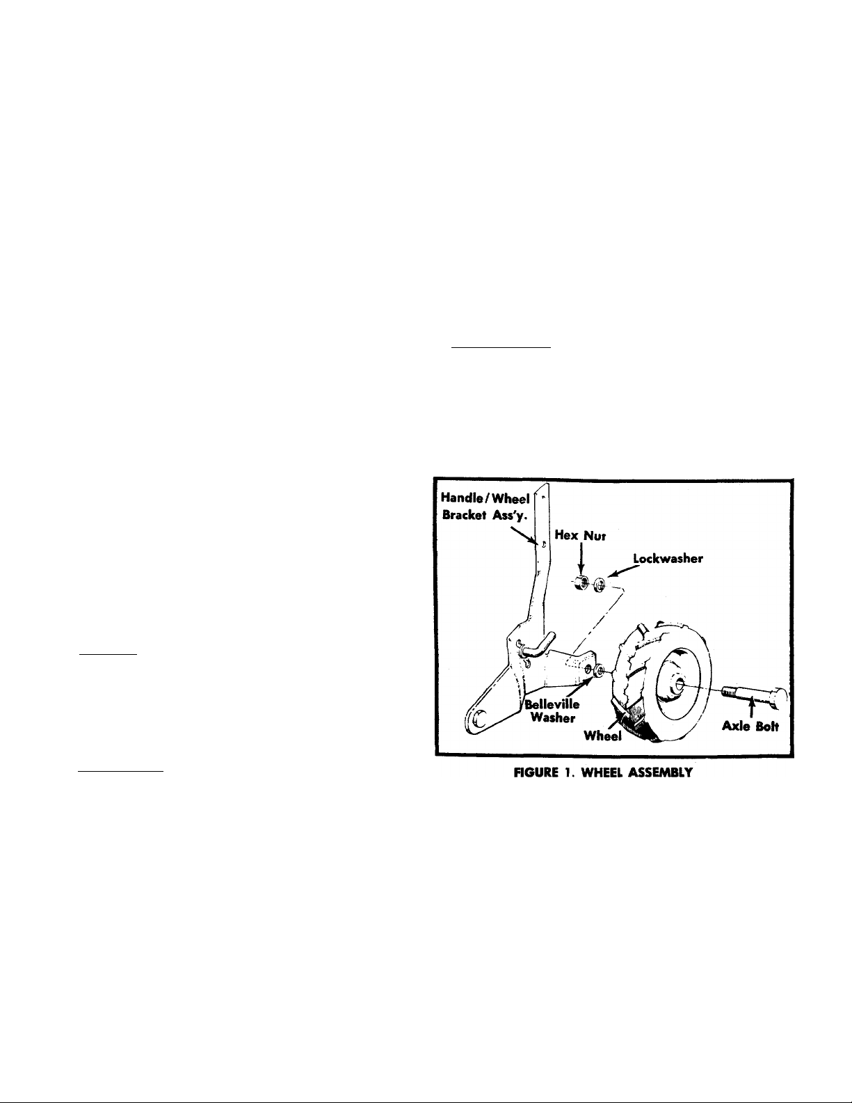
WHEEL ASSEMBLY
Insert axle bolt into wheel. Place Belleville washer on
threaded part of axle bolt. Crown of washer should be
positioned towards the wheel. Insert axle bolt in wheel
mounting hole of handle/wheel bracket assembly and
fasten with lockwasher and hex nut. See figure 1.
TINE ASSEMBLY
Step 1. The inner tine assemblies are already assem
bled to the tiller.
Step 2. The outer tine assemblies are inverted on the
tine shaft and MUST be removed and turned
around.
Step 3. Remove the outer tine assembly and turn
around so that the sharp edge of the tines
enters the soil first. Secure with bolt and lock
nut. See page 12.

HANDLE ASSEMBLY
CONTROL ROD
Assemble the handle to the bracket w^ith four cap
screws, washers and hex nuts. See figure 2.
Hex Nuts and Lockwashers
Hex Cap Sere
FIGURE 2. HANDLE ASSEMBLY
CLUTCH CONTROL
Place the clutch control lever through the handle pan
el. Attach it to the bracket with a screw and hex nut.
Two metal washers and a rubber washer are positioned
betwen the bracket and clutch control as shown in
figure 3.
Place the clutch control lever in neutral as shown in
figure 4. Screw the ferrule onto the control rod so that
approximately Va inch of threads are showing below
the ferrule. Assemble the ferrule to the pivot idler
bracket and secure with a cotter pin.
Adjust the ferrule location on the control rod so both
the forward and reverse belts are slack with the clutch
control lever in the NEUTRAL position. Secure with a
cotter pin.
Clutch Control Lever
Cotter Pin*
Control Rod
Cotter Pin
J
ff
FIGURE 4. CONTROL ROD
Cotter Pin
THROTTLE
Assemble throttle control as shown in figure 5.
FIGURE 3. CLUTCH CONTROL
FIGURE 5. THROHLE CONTROL
TAILPIECE
CHECK LIST BEFORE OPERATION
Attach the tailpiece to tiller with "U" clevis pin and
secure with spring pin. See figure 6.
NOTE
The "U" channel bracket assembly has
been assembled loose so that the tail
piece can be easily assembled to the
unit. After assembly of tail piece tighten
nuts and bolts tightly. See figure 6.
FIGURE 6. TAILPIECE
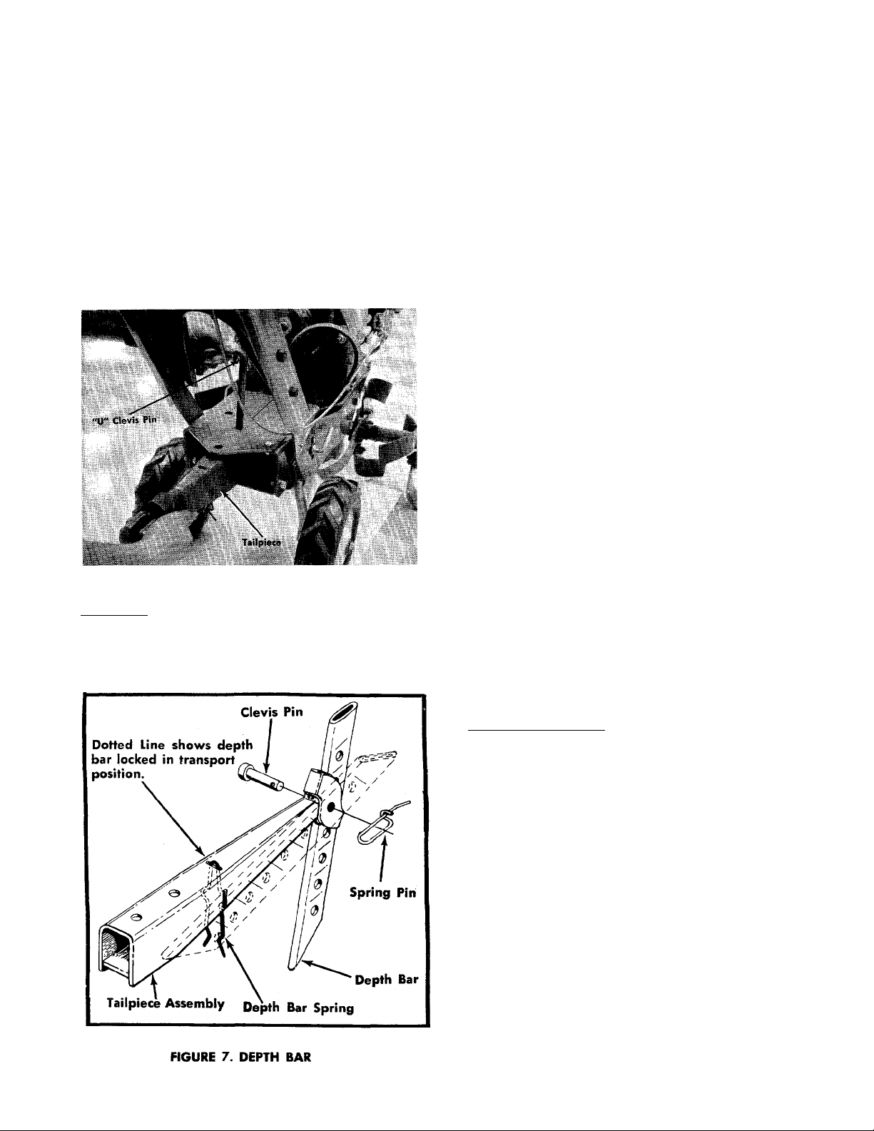
DEPTH BAR
Attach the depth bar to the tailpiece with a clevis
pin and secure with the.spring pin. See figure 7.
1. Remove spark plug wire from spark plug and
ground. Check tiller tines for proper installation.
With throttle control lever set on STOP position and
the clutch control handle set in FORWARD position,
slowly crank engine to determine direction of tine
rotation. Be sure all tines are mounted so the sharp
ened edges enter the soil first.
2. Place the clutch control lever in the NEUTRAL po
sition. Slowly crank engine. Ishe tines should
not rotate. If they do, readjust control rod.
3. Check all nuts and bolts for correct tightness. This is
especially important during the initial operation
period. Make the same check periodically there
after.
4. Check throttle control for proper setting. Move
throttle control knob to STOP position. Move lever,
to which control wire is fastened at engine, to
CLOSE position and retighten screw to secure throt
tle control wire assembly.
5. Check gear case for proper lubricant level. With til
ler on a level surface, lubricant level should be up
to the front pipe plug opening. This can be checked
by removing front pipe plug. Maintain correct lu
bricant level with Molilube SAE 140 gear oil or
equivalent. The gear case holds five (5) ounces of
lubricant.
6. Fill fuel tank. Clean, fresh, regular grade gasoline
should be used at all times.
7. Check engine crankcase for proper oil level. The en
gine is shipped without oil in the crankcase. Be
sure crankcase is FULL. See engine manual.
STARTING YOUR TILLER
1. Be sure clutch control lever is in NEUTRAL posi
tion.
2. Move throttle control lever to STOP position.
3. Move choke lever, located at the engine, to CHOKE
position. Refer to your engine manual.
4. Pull the starter rope to start the engine. More than
one pull may be required the first time. When the
engine fires, move the throttle control lever to RUN
position.
6. Use Choke as needed to keep engine operating
during warm-up period.
7. Check and make sure tines do not turn in NEUTRAL
position.
8. To stop engine, move throttle control lever to STOP
position. Keep throttle control lever in STOP posi
tion at ail times when tiller is not in use.

NOTE
OPERATING INSTRUCTIONS
A brief break-in period is essential to
insure maximum engine life. This con
sists of running the engine at half speed
for a period of time required to use one
tank of gasoline. This is necessary on
the initial run only. It is also recom
mended that the oil be changed after
five (5) hours of operation. This allows
for the removal of impurities which
may have accumulated during the breakin period. Subsequent oil changes
should be made as stated in the engine
manual. Always check oil before using
your tiller especially during the break-in
period. Be sure oil level is adequate.
HANDLE ADJUSTMENT
The handle may be adjusted to five different heights
by loosening the adjusting screw on each side of the
handel and pivoting the handle up or down. See figure
8.
For your own convenience and safety, observe all safe
ty suggestions shown on page 2. Your tiller
is not a toy, it is a precision piece of power equipment.
Treat it as such.
It is important to recognize the fact that the forward
and penetrating action of the rotary tiller is obtained
from the rotating action of the tines in the soil. The
depth bar acts as a brake for the tiller and controls the
depth and speed at which the machine will operate. By
lowering the setting of the depth bar, the forward
speed of the machine is reduced and the working
depth of the tines is increased. Raising the setting of
the depth bar increases the forward speed and reduce^
the working depth. When soil conditions are severe
and several passes must be made over a certain area,
the depth bar setting should be lowered each time a
pass is made. Further control of tilling depth and travel
speed can be obtained by variation of pressure on the
handle or the throttle setting. A downward pressure
on the handles will increase the working depth and
reduce the forward speed. An upward pressure on
the handies will reduce the working depth and in
crease the forward speed. The type of soil and working
conditions will determine the actual setting of the
depth bar and the handle pressure required.
NOTE
FIGURE 8. HANDLE ADJUSTMENT
TAILPIECE ADJUSTMENT
The tailpiece can be made stationary or free floating.
To be free floating simply lift the "U" clevis and rotate
"U" clevis to engage forward hole and push down.
See figure 8. See figure 2 for stationary position.
If the tines tend to bounce instead of
cutting into the soil, one or more sets
of tines may be on backwards. The cut
ting edge of the tines should enter the
soil first.
1. Tine engagement and forward travel is achieved by
moving the clutch control lever to FORWARD po
sition. Tine rotation and forward motion are stooped
by moving the clutch control handle to NEUTRAL
position. Reverse tine action and reverse travel mo
tion can be maintained by HOLDING the clutch con
trol lever in REVERSE position. Releasing the lev
er stops reverse operation automatically.
2. The throttle control lever adjusts the engine speed.
It also gives finger tip control of the carburetor and
magneto stop switch. With the throttle control knob
pushed completely forward, the carburetor is in
START position. Pulling the knob back slightly ad
justs the engine speed to FAST. Pulling, the knob
back further reduces the engine speed to SLOW.
When the knob is pulled completely back, the mag
neto stop switch grounds out the spark and stops
the engine.
3. With the depth bar positioned out of ground
engagement position, self propelled transporting
of the tiller is easily achieved. With no pressure
on the handles and the throttle control set for SLOW
engine speed, move the clutch control handle to
the FORWARD position and let the tiller gently pro
pel itself.
 Loading...