

Page 1

OWNERS
MANUAL
75
8 H.P.
ASSEMBLY
OPERATION
MAINTENANCE
PARTS LIST
REAR TINE
TILLER
Model Number
214-412-000
Important:
Read Safety Rules and
Instructions Carefully
PRINTED IN U.S.A.
Thank you for purchasing an
American built product.
FORM NO. 770-3189
Page 2

INDEX
Safe Operation Practices
Assembly...............................................................4
Controls.................................................................8
Operation.............................................................11
How To Use YourTiller
Adjustments
........................................................
......................................
.......................................
r
LIMITEiD WARRANTY
♦
♦
♦
♦
♦
♦
♦
♦
For one year from the date of original retail purchase, MTD PRODUCTS INC will either
repair or replace, at its option, free of charge, F.O.B. factory or authorized service firm, any
part or parts found to be defective n material or workmanship. Transportation charges for
the movement of any power equipment unit or attachment are the responsibility of the pur
chaser. Transportation charges for any parts submitted for replacement under this warran
ty must be paid by the purchaser ur less such return is requested by MTD PRODUCTS INC.
This warranty will not apply to any part which has become inoperative due to misuse, ex
cessive use, accident, neglect, improper maintenance, alterations, or unless the unit has
been operated and maintained in accordance with the instructions furnished. This warran
ty does not apply to the engine, mo or, battery, battery chargeror component parts thereof.
Please refer to the applicable man jfacturer’s warranty on these items.
11
13
3
Lubrication .........................................................14
Maintenance
Off-Season Storage
Illustrated Parts.......................................18, 20, 22
Parts List.................................................19, 21, 23
Parts Information...............................................Back Cover
......................................................
............................................
14
16
♦
♦
♦
♦
♦
♦
♦
t
♦
♦
♦
♦
This warranty will not apply where the unit has been used commercially.
Warranty service is available through your local authorized service dealer or distributor. If
you do not know the dealer or distri Dutor in your area, please write to the Customer Service
Department of MTD.
The return of a complete unit will r ot be accepted by the factory unless prior written per
mission has been extended by MT ).
♦
♦
This warranty gives you specific legal rights. You may also have other rights which vary
from state to state.
V
WARNING
This unit is equipped with an internal con bustion engine and should not be used on or near any unim
proved forest-covered, brush-covered or grass-covered land unless the engine’s exhaust system is
equipped with a spark arrester meeting applicable local or state laws (if any). If a spark arrester is used, it
should be maintained in effective working order by the operator.
j
♦
♦
♦
♦
♦
♦
In the State of California the above is required by law (Section 4442 of the California Public Resources
Code). Other states may have similar laws, federal laws apply on federal lands. A spark arrester muffler is
available at your nearest engine authorized service center.
Page 3

I WARNING \
To reduce the potential for any injury, comply with the following safety instructions. Faiiure to compiy with
the instructions may resuit in personai injury.
SAFE OPERATION PRACTICES FOR TILLERS
1. It is suggested that this manuai be read in its
entirety before attempting to assembie or
operate this unit. Keep this manuai in a safe
piace for future reference and for ordering
repiacement parts.
2. Your tiiier is a precision piece of power equip
ment, not a piaything. Therefore, exercise ex
treme caution at aii times.
3. Read this Owner’s Manual carefully. Be
thoroughly familiar with the controls and the
proper use of the equipment.
4. Never allow children to operate a power tiller.
Only persons well acquainted with these rules
of safe operation should be allowed to use
your tiller.
5. Keep the area of operation clear of all per
sons, particularly small children and pets.
6. Do not operate equipment when barefoot or
wearing open sandals. Always wear substan
tial footwear.
7. Do not wear loose fitting clothing that could
get caught on the tiller.
8. Do not start the engine unless the shift lever
is in the neutral (N) position.
9. Do not stand in front of the tiller while starting
the engine.
10. Do not filace. feet and hands on or near the
tines when starting the engine or while the
engine is running.
11. Never attempt to make a wheel or depth bar
adjustment while the engine is running.
14. Check the fuel before starting the engine.
Gasoline is an extremely flammable fuel. Do
not fill gasoline tank indoors, when the engine
is running, or while the engine is still hot.
Wipe off any spilled gasoline before starting
the engine as it may cause a fire or explosion.
15. Do not run the engine while indoors. Exhaust
gases are deadly poisonous.
16. Be careful not to touch the muffler after the
engine has been running. It is hot.
17. Do not change the engine governor settings
or overspeed the engine. Excessive engine
speeds are dangerous.
18. Before any maintenance work is performed or
adjustments are made, remove the spark plug
wire and ground it on the engine block for
added safety.
19. Use caution when tilling near buildings and
fences. Rotating tines can cause damage or
injury.
20. Before attempting to remove rocks, bricks and
other objects from tines, stop the engine and
be sure the tines have stopped completely.
Disconnect the spark plug wire and ground to
prevent accidental starting.
21. Check the tine and engine mounting bolts at
frequent intervals for proper tightness.
22. Keep all nuts, bolts and screws tight to be
sure the equipment is in safe working condi
tion.
12. Do not leave the tiller unattended with the
engine running.
13. Do not walk in front of the tiller while the
engine is running.
23. Never store the equipment with gasoline in
the tank inside of a building where fumes may
reach an open flame or spark. Allow the
engine to cool before storing in any
enclosure.
Page 4

Depth iar
Adjustrr ent
Plate
ASSEMBLY
NOTE
This unit is shipped WITHOUT GAS
OLINE or OIL. After assembly, see
separate engine manual for proper
fuel and engine oil recommenda
tions.
-Contents of Hardware Pack: (See Figure 1)
A (1) Belleville Washer 3/8" I.D.
B (1) Compression Spring
0 (1) Hex Lock Nut 3/8-24 Thread
D (1) Hairpin Cotter
E (2) Shoulder Bolts
F (2) Belleville Washers V2" I.D.
G (2) Flat Washers V2" I.D.
H (2) Hex Top Lock Nuts 3/8-16 Thread
J (1) Ferrule
K (1) Hex Jam Nut 3/8-24 Thread
L (1) Handle Adjustment Lever
M (1) Hex Bolt 1/4-20 X 1.75" Long
N (1) Hex Lock Nut 1/4-20 Thread
O (1) Spring
P (1) Hex Bolt 3/8-16 X 1.75" Long
Q (1) Spacer .38" Long
R (2) Flat Washers 3/8" I.D.
S (2) Hex Nuts 3/8-16Thread
T (2) Hex Lock Nuts 3/8-16 Thread
U (1) Spacer .18" Long
V (1) Hex Bolt 3/8-16 X 1.5" Long
W (2) Flat Washers 1/4" I.D.
X (4) Belleville Washers 5/16" I.D.
Y (4) Hex Nuts 5/16-18 Thread
■DEPTH BAR INSTALLATION
1. Grease the depth bar adjustment slots with an
automotive chassis grease.
2. Place hex bolt (V) through the hole in the
depth bar adjustment plate as shown in figure
2. The head of the bolt must be to the right
side of the tiller. Place smaller spacer (U) on
the hex bolt.
FIGURE 3.
¡*■1
NOTE
The right and left side of your tiller
is determined from operator’s posi
tion.
■3. Place slot in depth bar handle assembly over
the spacer and hex bolt. Secure with flat
washer (R) and hex nut (S), tightening secure
ly. Place one end of spring (O) onto the bolt.
Thread hex lock nut (T) on the bolt until the
two nuts are approximately 1/8" apart. See
figure 3.
Page 5
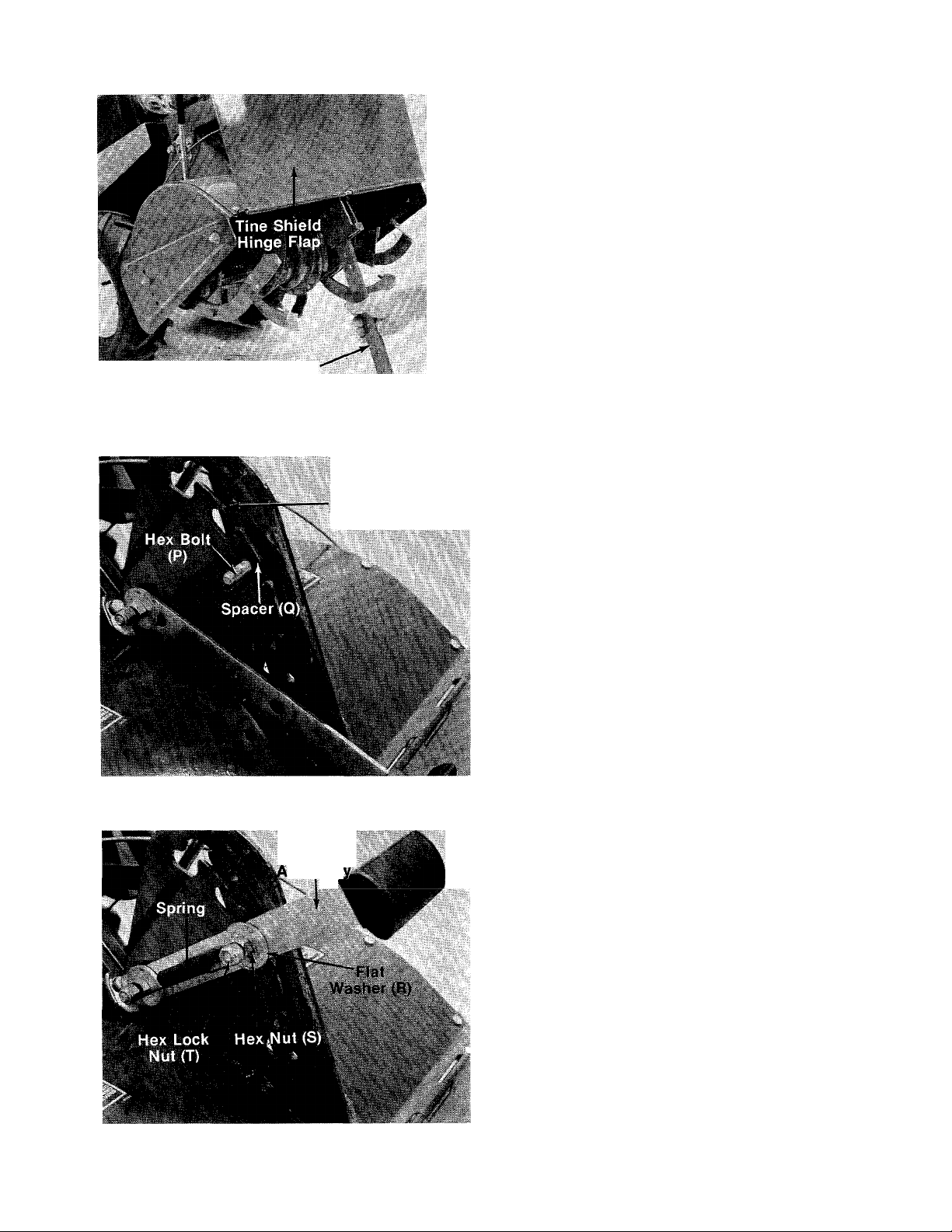
FIGURE 4.
Raise the tine shield hinge flap assembly. In
sert the depth bar assembly up through the
-tine shield assembly as shown in figure 4.
Depth Bar
Assembly
Depth Bar
Assembly
5. Place hex bolt (P) through depth bar assembly
and through notches in depth bar adjustment
plate. Head of hex bolt must be to right side of
the tiller. Place spacer (Q) on hex bolt. See
— figure 5.
FIGURE 5.
FIGURE 6.
Depth Bar
Handle
ssembi
6. Place hole in depth bar handle assembly over
the spacer and hex bolt. Secure with flat
washer (R) and hex nut (S), tightening secure
ly, then backing off one turn. Handle must be
able to pivot freely. See figure 6.
Place end of spring onto hex bolt. Thread hex
lock nut (T) on the bolt until the two nuts are
approximately 1/8" apart. See figure 6.
Page 6

Assemble
in this
order
Assemble the side shields to the tine shield as
-shown in figure 7, using belleville washers (X)
(cupped side against the side shields) and hex
nuts (Y). Side shields will be adjusted up or down
as the depth bar is adjusted, as described in the
Operation section.
HANDLE ASSEMBLY
1. Place the handle assembly in position on the
tiller so that the holes in handle line up with
holes in mounting bracket.
2. Place flat washer (G) and belleville washer (F)
over shoulder on shoulder bolt (E). Place
shoulder bolt through handle mounting holes.
Secure with hex top lock nut (H) from the in-
-----
side of handie. See figure 8.
FIGURE 8.
Hex Bolt (M)
Ra. \
Washer (W) V'
Handle , ,
Adjustment (N) Handle
Rod Adjustment
FIGURE 9.
Lever
%
3. To assemble the handle adjustment lever (L),
hook handle adjustment rod (already on han
dle) into lever. Hook to the outside.
Place a flat washer (W) on either side of the
4.
handle inside of the handle adjustment lever.
Secure with hex bolt (M) and lock nut (N). See
figure 9. Do not over tighten. Handle adjust
ment lever must pivot freely.
Page 7

THROTTLE CONTROL INSTALLATION
Assemble the throttle control to the handle panel
as follows.
1. Hold the throttle control assembly beneath
the handle panel. Turn the control sideways
and insert the lever up through the wide por
tion of the slot on the handle panel. See figure
■10A.
2. After the end of the lever is through the slot,
turn and then tip the control forward as shown
in figure 8B to slide it through the slot.
NOTE
The lever must be all the way to the
back of the control housing as
shown in figure 10B.
'Belleville
Washer (A)
Compression
Spring (B)
3. Push the control back into the slot in the han
dle panel and press in place. Be certain the
—control is locked securely into the slot.
GEAR SHIFT ROD INSTALLATION
1. Assemble notched edge of gear shift lever so
notch faces forward. Place gear shift lever
through slot in handle panel. Place bottom
hole in gear shift lever over weld stud. Secure
with belleville washer (A), compression spring
------
(B) and hex lock nut (C). See figure 11.
Tighten hex lock nut until nut is flush with
2.
stud. See figure 11.
FIGURE 11.
Page 8

FIGURE 12.
3. Thread hex jam nut (K) on one end of gear shift
rod. Then thread gear shift rod into ball joint
on the top of pivot horn assembly 10 to 12
complete turns, approximately I/2 inch. See
—figure 12. Lock hex jam nut against ball joint.
4. Thread ferrule (J) on other end of gear shift
— rod. See figure 13.
5. Secure ferrule in gear shift lever as shown in
figure 13 with hairpin cotter (D).
Hairpin
Cotter (D)
errule (J)
Gear Shift ^bd
in Front of
Gear Shift Lever
FIGURE 13.
Gear Shift Rod Adjustment
A
Service engine with oil and gasoline
before making this adjustment.
Refer to the separate engine
manual packed with your tiller.
1. Place the gear shift lever in “NEUTRAL” (N)
position.
2. Place the tine engagement lever in the
disengaged position. See figure 22.
3. Place wheel engagement lever in the
disengaged position. See figure 23.
4. Place the throttle in the “START” position.
CAUTION
After all assembly is completed,
the gear shift rod must be ad
justed prior to initial operation.
5. Move choke lever down (if engine is cold). See
figure 17.
6. Start the engine.
7. Engage the gear shift lever through the five
gears with the engine running and return to
“NEUTRAL” (N).
8. Stop the engine.
9. Remove the hairpin from ferrule and pull out
of gear shift lever.
10. Place gear shift lever in first gear (and pull
lever to rear of slot). Adjust the ferrule to fit
gear shift lever, and replace the hairpin.
11. Repeat steps 6 through 10 to make the final
adjustment.
Page 9

CONTROLS—Location and Use
Gearshift Lever
The gear shift lever is located in the center of han
dle panel.
Hl^ note
The engine must be running to
move the gear shift lever. Shifting
gears with the engine off will
cause damage to the clutch control
rod.
1. Forward (1 thru 5)—Move the lever to the left
and forward for each gear. See figure 14.
»
- V
J
aw
FIGURE 15.
Throttle Control
The throttle control lever is located on the right
hand side of handle panel and controls the engine
speed.
1. Start—Push throttle control lever forward
(down) to start position. See figure 16.
2. Stop—Pull lever back (upward) to stop the
engine.
■''V
FIGURE 14.
A. Use (1) first and (2) second gears when
breaking the sod for the first time.
B. Use (3) third and (4) fourth gears when till
ing soil which has been tilled before.
C. Use (5) fifth gear for pulverizing soil or for
transporting the tiller.
CAUTION
Use first speed only when operating
the tiller for the first time.
2. Neutral (N)—Move lever to detent marked
“N.”
3. Reverse (R)—Raise up on the handles to lift
the tines out of the ground and pull the gear
shift lever back (upward) slowly to obtain
reverse. Always use caution when using the
reverse. When using reverse, if gear shift lever
is released it will snap back into neutral (N).
See figure 15.
m
FIGURE 16.
Choke
The choke is located on the engine just below the
air cleaner. To choke the engine, move the choke
lever down. See figure 17.
Page 10

FIGURE 17.
Handle Adjustment Lever
The handle adjustment lever is located (»n the
right hand handle bar. See figure 18.
Squeeze up on handle adjustment lever anc place
the handle in one of nine (9) positions. See figures
19, 2C and 21.
If the locking pin does not withdraw from the han
dle positioner assembly or if the locking pin does
not seat securely into the holes in the handl 5 posi
tioner assembly, adjustment is required. Refer to
Adjustment Section on page 13.
Handle has three vertical
positions in the center
FIGURE 19.
Handle has three vertical
positions to the right
FIGURE 18.
Right Hand
Handle Bar
'V
'Hafndl'e
Adjustments .r ^
¡. ‘ •*
i-*
iM
ilH!
FIGURE 20.
FIGURE 21.
10
'W,
Handle has three vertical
positions to the left
'•ts ■
'■f i
■I' 1
Page 11

^ WARNING I
(D
Before using the tiller, check to be
certain the tines are assembled
properly (sharp edge of the tines
must enter the soil first). Refer to
Operation Section.
Wheel Engagement
Lever (Disengaged/
Position)
\ WARNING \
The gear shift lever must be in
Neutral (N) position before engaging
or disengaging the tine and wheel
engagement levers.
Tine Engagement Lever
The tine engagement lever is located on the left
side of tiller.
To engage tines, move the lever outward. To
disengage tines, move the lever inward. See figure
22.
NOTE
It may be necessary to slightly
engage gear shift lever to align the
gears.
jagement
(Engaged
sition)
FIGURE 23.
OPERATION
^^CAUTION
Engine is shipped without oil.
BEFORE STARTING
1. Before operating tiller for the first time or if
tines have been removed and reassembled for
any reason, check to be certain the tines are
assembled correctly. The sharp edge of the
tines must enter the soil first as shown in
figure 24. (Figure 24 illustrates the left hand
tines, viewed from the left hand side of the
tiller. Right hand tines rotate in the same
direction as the left hand tines.)
»ment S
■
as
FIGURE 22.
Wheel Engagement Lever
The wheel engagement lever is located on the
right side of tiller.
To engage wheels, move the lever outward. To
disengage or stop wheels, move lever inward. See
figure 23.
FIGURE 24.
2. Fill crankcase with oil as instructed in the
separate engine manual packed with your
unit.
3. Fill fuel tank with clean, fresh, lead-free, lowlead or regular grade leaded gasoline.
4. Open fuel shut-off valve.
11
Page 12

TO START ENGINE
^ WARNING ^
BE SURE NO ONE IS STANDING IN
FRONT OF THE TILLER WHILE THE
ENGINE IS RUNNING OR BEING
STARTED.
1. Place the gear shift lever in “NEUTRAL” (N)
position. See figure 14.
2. Place the tine engagement lever ii the
disengaged position. See figure 22.
3. Place the wheel engagement lever in the
disengaged position. See figure 23.
4. Place the throttle control lever in “S' ART”
position.
5. Move choke lever down to choke engin i. See
figure 17.
NOTE
A warm engine may not require
choking.
6. Stand at side of tiller. Grasp the starter t andle
and pull out rapidly. Return it slowly :o the
engine. Repeat as necessary.
7. After engine starts, move choke lever gradual
ly to “OFF” position.
Refer to engine manual for additional engine Infor
mation.
TO STOP ENGINE
1. Move throttle control to “OFF” positior.
2. Disconnect spark plug wire and ground
vent accidentally starting while equipment is
unattended.
1
o pre
HOW TO USE YOUR
TILLER
A. Forward speeds: First and second speeds are
generally used for tilling sod or soil which has
not been tilled before. Third and fourth speeds
are usually used for fine tilling or cultivating.
The fifth speed is for pulverizing soil or for
transporting the tiller. The soil conditions in
your area will determine the speed you will
want to use.
IMPORTANT
Do not shift gears unless the engine
is running. If the engine should stall
while in gear, you must proceed as
follows;
1. ) Disconnect and ground the spark plug wire
against the engine.
2. ) Move tine and wheel engagement levers to
the disengaged position.
3. ) Pull the recoil starter rope, and at the same
time pull back on gear shift lever. Pull the
rope out as many times as it takes to move
the gear shift lever into neutrai (N) position.
Do Not force shift lever back into neutral at
any time.
4. ) Move the gear shift lever through the for
ward speeds, neutral and reverse. Readjust
control rod if necessary.
B. Neutral (N): The neutral detent on the handle
panel is used when starting and stopping the
tiller and going from a forward speed to
reverse.
C. Reverse (R) Gear; The reverse gear is a dead-
man type. If you put the tiller into reverse to
back up or to unclog the tines, and you let go
of gear shift lever, the reverse motion will stop.
Reverse will only work when you pull the gear
shift lever back and hold it in that position.
Raise the handles and lift the tines out of the
ground before putting the tiller in reverse gear.
I WARNING ^
When operating the tiller for the
first time, use the depth bar setting
that gives 1 inch of tilling depth
(second slot from the bottom).
Refer to figure 25. Use first speed
only.
Your tiller has a variable speed pulley which
allows you to change gears, First (1) through Fifth
(5), without stopping. The gear shift le>er is
located on the top center of handle panel. There
are Five (5) forward speeds. Neutral (N and
Reverse (R).
A
CAUTION
Placing the tiller in reverse with the
tines in the ground will cause pre
mature wear of the reversing disc.
TILLING
Tilling depth is controiled by the depth bar which
can be adjusted to five different settings. See
figure 25. Adjust the side shields as shown in
figure 25 as you adjust the depth bar. Be certain
spark plug wire is disconnected and grounded
against the engine.
1. When using the tiller for the first time, use the
second adjustment slot from the bottom (1 " of
tilling depth). See figure 25.
12
Page 13

2. When breaking up sod and for shallow cultiva
tion, use the setting which gives 1" of tilling
depth (second slot from the bottom). Place
the side shields in their lowest position. For
further depth, raise the depth bar and side
shields and make one or two more passes
over the area.
3. When tilling loose soil, depth bar may be
raised to the top slot to give the deepest till
ing depth. Raise the side shields to their
highest position.
4. To transport tiller, lower the depth bar (use
bottom adjustment slot).
\ WARNING j
Engage wheel drive before engaging
the tine engagement lever.
NOTE
To transport tiller, do not engage
the tine engagement lever. Engage
the wheels only.
For best results, it is recommended the garden be
tilled twice (lengthwise, then widthwise) to
pulverize the soil.
ADJUSTMENTS
HANDLE ADJUSTMENT LEVER (See Figure 26)
Use This
Position
First Time
DEPTH BAR
Hole for Lowest
Side
Shield I
SIDE SHIELDS
Use This
Position,
Use This Hole
for Highest Position
NOTE
Figure 26 is viewed from the bottom
of handle panel.
Position A. Use if not enough free play.
Position B. Normal setting.
Position C. Use if pin will not withdraw complete
ly from bracket.
To make the adjustment, loosen hex lock nut and
reposition the rod in Position A, B or C. See figure
tti
■■ ■
tion A
ition B
ition C
FIGURE 25.
To adjust the depth bar, lift up on the tiller
handles. Pull the depth bar handle assembly and
move the depth bar to desired setting. Release the
handle. See figure 25.
To operate the tiller:
1. Select the depth bar setting.
2. Start engine as instructed on page 12.
3. Engage wheel and tine engagement levers.
4. Move gear shift lever to first speed position
(wheels and tines will be moving).
FIGURE 26.
CONTROL BRACKET ADJUSTMENT
When the belt has become worn and/or stretched
or the friction wheel has become worn, make the
following adjustment.
Move the control bracket to the bottom hole on
the pivot horn assembly and readjust the gear
shift rod. See figure 27.
13
Page 14

Pivot Hor,
Assembly
FIGURE 27.
THROTTLE CONTROL CABLE ADJUSTMENT
1. Place the throttle control lever in “STOP”
position.
2. Loosen the casing clamp screw and move the
throttle control wire in as far as possible. See
figure 28.
3. Tighten the casing clamp screw.
Never make unnecessary adjustments. The fac
tory settings are correct for most applications. If
adjustments are needed, refer to the separate
engine manual packed with your tiller.
LUBRICATION
TRANSMISSION
The transmission is lubricated and sealed at the
factory. It requires no additional lubrication
unless the transmission is disassembled. To fill
with grease, lay the left half of the transmission
on its side, add 28 ounces of Plastilube #0 grease
and assemble the right half to it. This grease can
be purchased from your nearest service dealer.
(Order Part No. 737-0133.)
DEPTH BAR ADJUSTMENT SLOTS
Clean and grease the depth bar adjustment slots
at least once a season with an automotive chassis
grease.
PIVOT POINTS
Lubricate all pivot points and linkages at least
once a season with light oil.
FIGURE 28.
CARBURETOR ADJUSTMENT
^ WARNING \
If any adjustments are made to the
engine while the engine is running,
(e.g. carburetor), disengage all
clutches and tines. Keep clear of all
moving parts. Be careful of heated
surfaces and muffler.
Throt le
Win
Conti ol
MAINTENANCE
WARNING
(S)
Disconnect the spark plug wire and
ground it against the engine before
performing any repairs or main
tenance.
^ IMPORTANT
If for any reason the tines are re
moved from the tiller, be certain the
tines are reassembled so that the
sharp edge of the tines enter the
soil first. Refer to item number
one under “Operation.”
ENGINE OIL
After the first two hours of operating a new
engine, drain the oil from the crankcase while the
engine is still hot and refill the crankcase with
new oil; thereafter change the oil after every 25
hours of operation.
To avoid spilling gasoline on your lawn or
driveway, plan to change the oil when the gasoline
tank and carburetor are empty.
To change the oil, refer to the separate engine
manual.
14
Page 15

Check oil level every eight hours of operation. Be
sure level is maintained full to point of overflow
ing.
AIR CLEANER
Under normal operating conditions, the air
cleaner, located on top of the carburetor, must be
serviced after every ten hours of use. Under ex
tremely dusty operating conditions, the air
cleaner must be serviced after every hour of
operation.
To service the air cleaner, refer to the separate
engine manual packed with your tiller.
A
Never run your engine without air cleaner com
pletely assembled.
CAUTION
Grommet
FIGURE 29.
LIMITED TORQUE CLUTCH
If the limited torque clutch is disassembled for
any reason, reassemble as shown on page 22.
Filter
Valve
CLEANING ENGINE AND TINE AREA
Any fuel or oil spilled on the tiller should be wiped
off promptly. Dirt, leaves and other debris must
not be left to accumulate around the cooling fins
or the engine or on any part of the tiller. Clean the
underside of the tine shield after each use. The
dirt washes off the tines easier if washed off im
mediately instead of after it dries.
SPARK PLUG
The spark plug should be cleaned and the gap
reset every 25 hours of engine operation. Spark
plug replacement is recommended at the start of
each tiller season; check engine manual for cor
rect plug type and gap specification.
FUEL SHUT-OFF VALVE AND FILTER
The valve and filter is located on the bottom of the
gasoline tank located on top of the tiller.
Turn the valve knob in to shut off the fuel flow.
Turn the valve knob out to operate the tractor. See
figure 29.
The entire valve can be pulled out to clean the
filter. When reassembling, place the rubber grom
met into the gasoline tank first, then push the
valve all the way in.
\ WARNING \
NOTE
Torque setting is 550 to 650 in. lbs.
If you do not have a torque wrench, proceed as
follows:
1. Run the first nut on until it touches the spring
bell washer.
2. Mark nut and plate with a scrib line.
3. Tighten nut 3/4 of a turn clockwise.
4. Then lock in place with the second hex jam
nut.
BELT REPLACEMENT
A
Do not use an off-the-shelf belt.
Your tiller has been engineered with belts made of
special material (Kevlar Tensile) for longer life and
better performance. They should not be replaced
with an off-the-shelf belt.
If belt replacement is required, order belt or belts
by part number from your nearest authorized
dealer.
Part No. 754-0220 Part No. 754-0268
5/8" X 27" Short Belt 5/8" x 51" Long Belt
Front (Short) Belt Removal
1. Remove belt cover by removing the four self
tapping screws and flat washers. See figure
30.
CAUTION
Only use factory approved parts if
repairs are needed on the gasoline
tank, grommet, valve or gasoline
line.
15
, CAUTION
A
Muffler may be hot in the area
of belt cover. Only remove the belt
cover when engine is cool.
Page 16

Self-Tapping
Screws
Self-Tappin}
Screws
FIGURE 30.
2. Place gear shift lever in neutral position Hoid
friction disc with one hand. Remove three hex
bolts and lock washers which hold the friction
disc to the variable speed pulley. See figure
31. Lift belt off the variable speed pulle/.
Lift up on the idler pulley by hand, and remove
3.
the belt from beneath the idler pulley. Lift belt
off the transmission pulley and variable speed
pulley. See figure 32.
FIGURE 32.
NOTE
Upon reassembly of friction disc,
tighten the three bolts equally.
FIGURE 31.
3. Remove the hex bolt and internal lock u/asher
which holds the belt guard to the engir e. See
figure 31. Remove the belt guard. Remc ve and
replace the belt.
4. Reassemble in reverse order with the new
belt.
■i^NOTE
Be certain to assemble the new rear
belt in the second groove on the variabie speed pulley.
TIRE CHAINS
It may be necessary to move the right hand wheel
assembly to the extreme outside position when
using tire chains. See iilustration below.
Rear (Long) Belt Removal
1. Follow step numbers 1 and 2 under “Front
Belt Removal.”
2. Place the gear shift lever in one of the f Drward
gears (as far forward as possible).
16
Page 17

OFF SEASON STORAGE
If the tiller is to be inoperative for a period longer
than 30 days, the following precautions are recom
mended. Keep your tiller in a weatherproof dry
area. If stored for over 30 days the following steps
will protect the essential engine parts from gum
deposits.
1. Working outdoors, drain all fuel from the fuel
tank. Use a clean dry cloth to absorb the small
amount of fuel remaining in the tank, then run
the engine until all fuel in carburetor is ex
hausted.
5. Wipe tines with oiled rag to prevent rust.
CAUTION
A
When storing any type of power
equipment in an unventilated or
metal storage shed, care should be
taken to rust proof the equipment.
Using a light oil or silicone, coat the
equipment, especially any springs,
bearings and cables.
t. WARNING {
DO NOT DRAIN FUEL WHILE
SMOKING, OR IF NEAR AN OPEN
FIRE.
2. Drain all the oil from the crankcase (this
should be done after the engine has been
operated and is still warm) and refill the
crankcase with clean new oil.
3. Disconnect the spark plug wire and remove
the spark plug from the cylinder. Pour about
six drops of engine oil into the cylinder, and
then pull the recoil starter several times to
spread the oil on the cylinder wall. Replace
the spark plug, but DO NOT connect the wire.
4. Clean the engine and the entire tiller
thoroughly.
TILLER WINTERIZING INSTRUCTIONS FOR USE WITH SNOW BLADE:
1. For cold weather (below 32°F.), drain oil from
tiller engine crankcase and replace with SAE
10W or 10W-20 detergent oil.
2. Replace any remaining fuel on hand or in the
engine fuel tank with a fresh supply of winter
grade fuel. Winter fuels contain additives for
faster starts. Keep fuel tank full.
NOTE
It may be necessary to enrich the
carburetor idle and high speed jets
1/8 to 1/4 turn (counterclockwise) for
good performance.
3. In the spring of the year, before the tilling sea
son, be sure to change engine oil back to SAE
30W detergent oil.
17
Page 18

TROUE LE SHOOTING CHART
SYMPTOM
POS ilBLE CAUSE(S)
Engine fails to start 1. Check ft el tank for gas.
2. Spark plug lead wire
discor nected.
3. Faulty spark plug.
Hard starting or loss of
1. Spark plug wire loose.
power
2. Dirty air cleaner.
Engine overheats
1. Carburetor not adjusted
propel ly.
2. Air flow restricted.
3. Engine c il level low.
Controls do not engage
Belts worn and/or
stretched.
SOLUTION
1. Fill tank if empty.
2. Connect lead wire.
3. Spark should jump gap between
control electrode and side elec
trode. If spark does not jump,
replace the spark plug.
1. Connect and tighten spark plug
wire.
2. Clean air cleaner as described in
engine manual.
1. Adjust carburetor. See engine
manual.
2. Remove blower housing and clean
as described in the engine
manual.
3. Fill crankcase with the proper oil.
Make control bracket adjustment.
See adjustment section of manual.
NOTE: For repairs beyond the minor adjust nents listed above, please contact your local service dealer.
18
Page 19

NOTES
19
Page 20

Model 412
20
Page 21

Model 412
REF.
NO.
PART
NO.
COLOR
CODE
DESCRIPTION
PARTS LIST
1 710-0136 Hex Bolt 1/4-20 X 1.75" Lg.*
2 749-0268
720-0180
3
712-0107 Hex Cent. L-Nut V4-20 Thd.
4
14844
5
04831
6
7 749-0269
04810
8
9 714-0149
Handle—R.H.
Grip
Clutch Grip
Handie Panei Ass’yHandle—L.H.
Clutch Handle Ass’yHairpin Cotter
10 736-0105 Belleville Wash. .38" I.D.
11
732-0193
Compression Spring .88"
O.D. X .81" Lg.
712-0214 Hex Cent. L-Nut 3/8-24 Thd.
12
13 747-0278 Gear Shift Rod
14 14734 Pivot Horn Ass’y.
15 736-0290 FI-Wash. .630 I.D. x 1.0" O.D.
X .063
714-0474 Cotter Pin 1/8" Dia. x .75"
16
Lg-*
17
15381
Tine Shield Ass’y.
18 710-0344 Hex Bolt 3/8-16 x 1.5" Lg.*
750-0527
19
Spacer .38 I.D. x .50 O.D. x
.18 Lg.
20 750-0528 Spacer .38 I.D. x .50 O.D. x
.38 Lg.
21 14843 Depth Bar Handle Ass’y.
w/Knob
22
711-0198
23 712-0798
24
712-0130 Hex Ins. L-Nut 3/8-16 Thd.
736-0227
25
Ferrule
Hex Nut 3/8-16 Thd.*
FI-Wash. .38 I.D. x 1.50 O.D. x
.13
26 712-0798 Hex Nut 3/8-16 Thd.*
27 732-0416 Spring—Depth Bar
28 712-0130
747-0252
29
Hex Ins. L-Nut 3/8-16 Thd.
Hinge Rod
30 04804 Tine Shield Hinge Flap
Ass’y.
31 15389 Side Cover Tine Shield—L.H.
15388 Side Cover Tine Shield—R.H.
(Not Shown)
14731 Depth/Drag Bar Ass’y.
32
710-0347
33
Hex Bolt 3/8-16 X 1.75" Lg.*
34 710-0604 Hex Wash. Hd. Self-Tap Scr.
5/16-18 X .62" Lg.
712-0292 Speed Nut
35 710-0830 Hex Bolt 3/8-24 x 3.0" Lg.
36 736-0169 L-Wash. 3/8" I.D.*
37 710-0623 Hex Wash. Hd. Self-Tap Scr.
38 738-0258 Shoulder Bolt .50" Dia. x .25"
Lg.
39 04841
Control Bracket
40 712-0116 Hex Ins. L-Nut 3/8-24 Thd.
41
736-0169 L-Wash. 3/8" I.D.*
42 736-0169 L-Wash. 3/8" I.D.*
43 736-0105 Belleville Wash.
*For faster service obtain standard nuts, bolts and washers
locally. If these items cannot be obtained locally, order by
part number and size as shown on parts list.
FOR MODEL 412 TILLER
REF.
NEW
PART
NO.
44
45
PART
NO.
710-0623
712-0241
COLOR
CODE
46 736-0169
47
711-0679
48
15295 Tine Adapter Ass’y.
49 15387 LH. Tine Ass’y. Comp.
15386 R.H. Tine Ass’y. Comp.
50 710-0192
51 736-0169 L-Wash. 3/8" I.D.*
52 712-0241
53 742-0244
54
742-0243 Tine—L.H.
55 714-0149 Hairpin Cotter
56 15385 Chain Case Ass’y. Comp.
57
712-0267
58 736-0119
59 14744
60 712-0130 Hex Ins. L-Nut 3/8-16 Thd.
736-0119
61
62 710-0601
723-0156
63
747-0254
64
712-0158
65
748-0516
66
67
04819 Pivot Handle Link
736-0289 Bushing Wash.
68
712-0267
69
736-0119
70
738-0143
71
72 736-0253
714-0474
73
732-0132
74
75 711-0663 Locking Pin
76 712-0221
77 712-0181
78 04812
748-0150
79
80 736-0192
81 04792
82
710-0458
83 747-0255
84 831-0692
85
710-0118
86 746-0502
87
712-0711
88 15390
736-0170
89
712-0267
90
736-0173
91
92
710-0191 Hex Bolt 3/8-24 x .75" Lg.
When ordering parts, if color or finish is important use the ap
propriate color code shown above, (e.g. Top Flite Red—04820
(463).)
21
DESCRIPTION
Hex Wash. Hd. Self-Tap Scr.
Hex Nut 3/8-24 Thd.*
L-Wash. 3/8" Scr.*
Clevis Pin
(Not Shown)
Hex Bolt 3/8-24 x 1.25" Lg.*
Hex Nut 3/8-24 Thd.*
Tine—R.H.
Hex Nut 5/16-18 Thd.*
L-Wash. 5/16" I.D.*
Handle Positioner Ass’y.
L-Wash. 5/16" I.D.*
Hex Wash. Hd. Self-Tap Scr.
Rod End 3/8-24 Thd.
Lower Handle Control Rod
Hex Nut 5/16-18 Thd.*
Pivot Handle Brg.
Hex Nut 5/16-18 Thd.*
L-Wash. 5/16" I.D.*
Shid. Bolt .500" Dia. x .660
Belleville Wash. .505" I.D. x
1.00" O.D.
Cotter Pin 1/8" Dia. x .75"
Lg.*
Compression Spring
Hex Ins. L-Nut 5/8-16 Thd.
Hex Top L-Nut 3/8-16 Thd.
Pivot Brkt. Ass’y.
Sleeve Brg. .50" I.D. x .62"
O.D. X 1.12" Lg.
FI-Wash. .50" I.D. x 1.00"
O.D. X .090
Handle Mtg. Brkt. Ass’y.
Carriage Bolt 5/16-18 x 1.75"
Lg.*
Handle Lock Rod
Throttle Control Box Ass’y.
Hex Bolt 5/16-18 X .75" Lg.*
Throttle Control Wire
Hex Jam Nut 3/8-24 Thd.
Side Shield
Bell-Wash.
Hex Nut 5/16-18 Thd.
FI-Wash. 1/4" I.D.
(463—Top Flite Red)
(447—Patina Silver)
NEW
PART
N
N
Page 22

Model 412
16 15 1
NOTE: The engine is not under warranty by
the tiiler manufacturer.. . If repairs or service
is needed on the engine; please contact your
nearest authorized engine ^
service outlet. Check the Find It Fast
“Yellow Pages” of your In The
telephone book under “En- Yellow Pages
gines—Gasoline.”
----------------------------
IMPORTANT
The chain case must be assembled to the
frame with 3/4" hex bolt, lock washer and
beileville washer as shown.
22
Page 23

Model 412 PARTS LIST FOR MODEL 412 TILLER
NEW
REF.
NO.
PART
NO.
1 723-0365
2 710-0876
3 736-0119
4
736-0231
15727
5
COLOR
CODE
DESCRIPTION
Gas Cap 53 736-0105
Hex L-Bolt 5/16-24 x 1.5" Lg. 54
L-Wash. 5/16" I.D.*
FI-Wash. 5/16" I.D. X 1.125"
O.D.
Friction Disc Ass’y. N
PART
REF.
NO.
55 710-0623
56 734-0806
6 710-0191 Hex Bolt 3/8-24 x 1.25" Lg.
7
761-0189
Friction Pad 57
8 738-0372 Shoulder Spacer 58 712-0116 Hex Ins. L-Nut 3/8-24 Thd.
9 14740 Idler Bracket 59
10 756-0225
11
717-0343
12
712-0130 Hex Ins. L-Nut 3/8-16 Thd. .75" Lg.
Fl-ldler2.75" Dia.
Variable Speed Ass’y.
60 736-0119 L-Wash. 5/16" I.D.*
61 710-0601
13 754-0220 “V”-Belt 5/8" X 27.0" Lg. 62 715-0139
14
714-0118
Sq. Key 1/4" X 1.50" Lg.*
15 726-0153 Cable Tie 63 747-0265
16
751-0225
17
18
710-0380
19 14826
—
Gas Tank 64 720-0143 Grip
Engine 65
Hex Bolt 5/16-18 X 1.75" Lg.*
Belt Cover Support Ass’y-
66
67
20 736-0114 Internal L-Wash. Va" I.D. 719-0237
21
710-0121 Hex Bolt 1/2-20 X .75" Lg. Shown)
22 756-0296 Engine Pulley Ass’y. 68
23
24
05080
750-0381
Friction Wheel Ass’y.
69
Spacer 04859
25 736-0119 L-Wash. 5/16" I.D.*
26 710-0621 Hex Bolt 5/16-18 X .50" Lg.* 70
28
741-0155
Ball Bearing 71 717-0382
29 05034 Bearing Housing 1-3/8" O.D. 72
30 736-0329
L-Wash. 1/4" I.D.* 74
31 712-0138 Hex Nut 1/4-28 Thd.* 75
32 712-0324 Hex Ins. L-Nut V4-20 Thd. 76
33 04837
Variable Speed Brkt. Ass’y.
77 736-0319
34 710-0106 Hex Bolt 1/4-20 X 1.25" Lg.* 78
35 738-0380
36 714-0115
37 736-0237 Fi-Wash. .686" I.D. X 1.25"
14741 —452
38
39
736-0119
40 712-0267
41
712-0214 Hex Cent. L-Nut 3/8-24 Thd.
42
723-0340
43
736-0326
44
712-0206
45
736-0169
Shid. Bolt 1/2" Dia. x .25" Lg. 79
Cotter Pin 1/8" Dia. x 1.0" 80
Lg.*
81 754-0268
82 736-0169
O.D.
Frame Ass’y.
83
84 756-0410
L-Wash. 5/16" I.D.* 85 710-0195
Hex Nut 5/16-18 Thd.* 86 710-0599
87
Weight 88 15290
FI-Wash. .50" I.D. x 1.0" O.D. 89
Hex Nut 1/2-13 Thd.* 90 736-0119
L-Wash. 3/8" I.D.*
91
46 04860 Weight Mtg. Brkt. 92 751-0171
47
710-0496
Hex Bolt 1/2-13 X 4.50" Lg.*
93
48 710-0152 Hex Bolt 3/8-24 x 1.00" Lg.* 94 751-0173
49
712-0130
50
736-0329
51 712-0138
52 732-0384 Spring Idler Bracket
Hex Ins. L-Nut 3/8-16 Thd.
L-Wash. 1/4" I.D.*
Hex Cent. L-Nut V4-28 Thd.
95
96 748-0296
97
98
PART
NO.
COLOR
CODE
DESCRIPTION
Belleville Wash. 3/8" I.D.
736-0169
L-Wash. 3/8" I.D.*
Hex Self-Tap Scr. 3/8-16 x
.75" Lg.
Wheel Ass’y. Comp.—R.H.
734-0807
Wheel Ass’y. Comp.—L.H.
(Not Shown)
710-0191 Hex Bolt 3/8-24 x 1.25" Lg.*
* ^ am %
Chain Case Ass’y. Comp.
Hex Tap Tite Scr. 5/16-18 x
Headed Spiral Pin 3/16 x
13/16" Lg.
Engagement Lever
741-0862
732-0863
Ball Detent .250" Dia.
Compression Spring
719-0238 Shift Housing—R.H.
Shift Housing—L.H. (Not
721-0162
04858
Gasket—Shift Housing
Shift Yoke Ass’y.—R.H.
Shift Yoke Ass’y.—L.H. (Not
Shown)
717-0383
Clutch Dog
Clutch Dog Driver
04841
15287
710-0314
736-0171
Control Brkt.
Shroud Belt Cover
Hex Bolt 7/16-20 x 1.00" Lg.
L-Wash. 7/16" I.D.
FI-Wash. .44 I.D. x 1.38" O.D.
04836
710-0230
736-0329
Friction Disc
Hex Bolt 1/4-28 X .50" Lg.
L-Wash. 1/4" I.D.*
“V”-Belt 5/8" X 51" Lg.
L-Wash. 3/8" I.D.*
710-0344
Hex Bolt 3/8" X 1.50" Lg.*
Input Pulley—Chain Case
Hex Bolt 1/4-28 X .62" Lg.
Hex Wash. Hd. Self-Tap Scr.
736-0173
FI-Wash. 1/4" I.D.
Tank Mounting Brkt.
710-0118
Hex Bolt 5/16-18 X .75" Lg.*
L-Wash. 5/16" I.D.*
735-0149
Bushing—Gas Line
Shut-Off Valve
723-0157
Clamp Gas Line
Gas Line 141/2" Lg.
15291
Brace
Floating Disc
736-0352
712-0331
Spring Bell-Wash.
Hex Jam Nut 1.0-14
NEW
PART
N
23
Page 24

Model 412
NOTE: Use 28 ounces of
Plastilube #0 grease. Order
part no. 737-0133.
24
Page 25

Model 412
REF.
NO.
10
11 721-0163
12 15383
15
20
21
22
23
24 719-0237
25 710-0601
27 717-0383
28
PART
NO.
1 741-0155
15384
2
738-0379
3
4 714-0122
750-0379
5
717-0210
6
7 750-0378
8 14899
736-0350
9
741-0381
05034
13
14 736-0329
712-0138 i
721-0192
16
17 736-0219
18 736-0169
712-0214
19
04859
04858
721-0162
741-0862
732-0863
719-0238
717-0382
COLOR
CODE
PARTS LIST FOR CHAIN CASE ASSEMBLY 15385
REF.
DESCRIPTION
Ball Bearing .62" I.D. x 1.38"
O.D. X .44
Chain Case R.H. Half
Input Shaft .62" Dia.
Sq. Key 3/16" x 3/16" x .75"
Lg.
NEW
PART
NO.
29 721-0102
30
31
32
33 14746
34
PART
NO.
712-0138
736-0329
741-0229
713-0313
Spacer .637" I.D. x .781" O.D.
X .85" Lg.
35 750-0352
Sprocket 9 Tooth x .62"
Shaft
Spacer .637" I.D. x .781"
36 04823
37
713-0250
O.D. X 1.44" Lg.
Tine Shaft Ass’y.
FI-Wash. 1.28" I.D. x 1.62"
39 717-0512
40
750-0563
O.D.
Flange Bearing 1.25" I.D.
Gasket—Housing
41
717-0511
42 748-0184
Chain Case L.H. Half
Bearing Housing 1-3/8" O.D.
43 750-0374
L-Wash. 1/4" I.D.*
Hex Nut 1/4-28 Thd.
44
741-0189
Seal 1.25" i.D.
Belleville Wash.
45 736-0259
L-Wash. 3/8" I.D.*
Hex Cent. L-Nut 3/8-24 Thd.
Shift Yoke Ass’y.—L.H.
46 04835
47 713-0312
Shift Yoke Ass’y.—R.H. (Not
Shown)
48 750-0314
Gasket—Shift Housing
Ball Detent .250 Dia.
Compression Spring
Shift Housing —L.H.
Shift Housing—R.H. (Not
Shown) 53
49 710-0195
50 736-0219
51 710-0629
52 736-0159
736-0119
Hex Tap-Tite 5/16-18 x .75" 54 710-0627
Lg.
Clutch Dog
Clutch Dog Driver
55 756-6297^*°
56 721-0165
57
714-0139
COLOR
CODE
DESCRIPTION
Seal 1.0" I.D. x 1.38" O.D.
Hex Nut V4-28 Thd.*
L-Wash. 1/4" I.D.*
Flange Brg. 1.00" I.D.
Sprocket Brg. Sleeve Ass’y.
#50 Chain—5/8" Pitch x 50
Links—Endless
Stepped Spacer 1.0" I.D. x
1.75" O.D.
Clutch Shaft Ass’y.
#420 Chain 1/2" Pitch x
58 Links—Endless
Gear Bearing—Sleeve Ass’y.
Spacer 1.25" I.D. x 2.0"
O.D. X .68" Lg.
Sprocket and Gear Ass’y.
Flange Brg. .628" I.D. x .753"
O.D.
Hub Sleeve .38" I.D. x .625"
O.D.
Flange Brg. 1.00" I.D. x
1.188" O.D.
FI-Wash. 1.0" I.D. x 1.62"
O.D.
Axle Shaft Ass’y.
#420 Chain Vz" Pitch 46
Links—Endless
Spacer 1.0" I.D. x 2.0"
O.D.
Hex Bolt 1/4-28 X .62" Lg.
Belleville Wash.
Hex Bolt 3/8-24 x 2.75" Lg.*
FI-Wash. 5/16" I.D.
L-Wash. 5/16" I.D.*
Hex L-Bolt 5/16-24 x .75" Lg.
Input Pulley—Chain Case
Cap Plug .250" Dia.
Sq. Key 3/16" x 2.0" Lg.
NEW
PART
nr.
Heavy Duty Rear Tine Garden Tiller Attachments Available for All-Season Use
31-0106 Depth Gauge Wheels (Pair)
31-0107 6-Tine Cultivator (Must be used with
31-0106 Depth Gauge Wheels)
31-0110 8" Furrower Opener
31-0111 15" Sweep Cultivator
31-0114 Wheel Weights (Pair)
31-0116 32" Leveling/Snow Blade (Must be used
with 31-0121 Front Hitch Mount)
31-0121 Front Hitch Mount (For 32" Blade)
Note: Attachments are available through your local dealer or from the factory:
Agri-Fab Inc., 303 W. Raymond Street, Sullivan, Illinois 61951 (217) 728-4334
31-0144 “V”-Bar Cultivating Kit
Kit Includes: “V”-Bar Frame, 4-Point
Cultivating Tines, Hiller/Furrower,
Depth Gauge Wheels (Pair).
To use these
necessary to:
1.
Remove the tine shield hinge flap assembly.
2.
Remove the depth bar assembly (except when
using the 8" furrower opener and 15" sweep
cultivator).
3.
Remove the tines.
25
attachments on the tiller, it
IS
Page 26

PARTS INFORMATION
POWER EQUIPMENT PARTS AND SERVICE
Parts and service are available through the authorized
firms listed below. All orders should specify the model num jer of
your unit, part numbers, description of parts and the quantity of
each part required.
Sfjrvice
NOTE: If any parts are found to be missing or d ifective upon assembly of this unit
that immediate repiacement can be made.
ALABAMA
Auto Electric & Carburetor Co.
ARKANSAS
Sutton’s Lawn Mower Shop . ..
CALIFORNIA
Billious'
COLORADO
FLORIDA
GEORGIA
ILLINOIS LYONS
INDIANA
IOWA
LOUISIANA
MARYLAND
MASSACHUSETTS
MICHIGAN
MINNESOTA
MISSISSIPPI
MISSOURI
NEW JERSEY
NEW MEXICO
NEW YORK
........................................
Spitzer Industrial Products Co.
Radco Distributors
Small Eng. Dist............................
East Point Cycle & Key
Keen Edge Co.............................
Parts & Sales Inc
Power Lawn & Garden Equip. . . . 2551 J.F. Kennedy ..
Suhren Engine Co
Center Supply Co
Morton B. Collins Co
Lorenz Service Co.......................
Power Equipment Dist.................
Hance Distributing Inc
Biloxi Sales 8. Service, Inc
Automotive Equip. Service ...
Ross-Frazier Supply Co
Henzier, Inc
Lawnmower Parts Inc
Spitzer Eng. & Parts
Gamble Dist., Inc.........................
......................
...............
........................
.......................
........................
...................
.................
..........
..............
.................................
.................
....................
BIRMINGHAM
.. 2625 4th Ave.S
NORTH LITTLE ROCK
. . 5301 Roundtop Drive
Box 368, Rt. 4
PORTERVILLE
.. 75 North D Street .., . )3257
DENVER
. . 6601 N.
Washington St
JACKSONVILLE
. . 4909 Victor St.
Box 5459
OPA LOCKA
. . 2351 N.W. 147th St. . .33054
EAST POINT
.. 2834 Church St
.. 8615 Ogden Ave. . ..
ELKHARÎ
. . 2101 Industrial Pkwy.
DUBUQUE
NEW ORLEANS
. . 8330 Earhart Blvd. ..
ТАКОМА PARK
.. 6867 New Hampshire
Ave
.............................
SPRINGFIELD
. . 300 Birnie Ave
LANSING
.. 2500 S. Pennsylvania .38910
MOUNT CLEMENS
. . 340 Hubbard
HOPKINS
. . 420 Excelsior Ave. W. .1,5343
BILOXI
.. 506 Caillavet St
KANSAS CITY
. . 3117 Holmes St
ST. JOSEPH
.. 8th and Monterey ... .(4503
ST. LOUIS
BELLMAWR
.. 717 Creek Rd
ALBUQUERQUE
.. 1023ThirdAve. N.W. .<7103
CARTHAGE
. . West End Ave
............
............
............
...................
...........
............
...............
...........
..........
..............
.............
. 55233
. ^2117
.30229
.12207
.:I0344
.30534
.36516
. 12001
. ’0118
.30912
.111107
.. 18043
.; 19533
.<4109
.<3125
.(8030
.13619
BRIGGS AND STRATTON,
AND SERVICE
Briggs & Stratton, Tecumseh
should be handled by your nearest authorized engine service firm.
listing Engines—Gasoline,
Lauson.
NORTH CAROLINA
OHIO
OKLAHOMA
OREGON PORTLAND
PENNSYLVANIA HARRISBURG
TENNESSEE
TEXAS
UTAH
A-1 Engine & Mower Co...
VIRGINIA
WASHINGTON
WISCONSIN
Automotive Supply Co. .. ... 123 S. Lin wood Ave.
Check the yellow pages of your telephone directory under the
Smith Hardware Co
Dixie Sales Company .... .. . 335 N. Green
Stebe’s Mid-State Mower Supply . Box 366, 71 High St... .43112
Bleckrie, Inc
National Central
Burton Supply Co
Victory Motors, Inc
Kenton Supply Co
EECO Inc
Thompson Rubber Co. ... ... 5222-24 N. Fifth St.... .19120
Bluemont Co
Frank Roberts & Sons . .. . . . R.D.2.............................
Scranton Auto Ignition Co.
Master Repair Service ... . . . 2000 Western Ave. . . .
American Sales & Service, Inc. ... 3035-43 Bellbrook . . .
Marr Brothers, Inc
Woodson Sales Corp
Bullard Supply Co
Engine House inc
RBI Corp
Bailey’s Inc
Horst Dist
............................
.............................
............................
.............
........................
..................
................
..............
...............
.......................
...............
...............
................
..........................
TECUMSEH AND PEERLESS
and Peerless parts and
Briggs & Stratton or Tecumseh
write to advise the factory so
GOLDSBORO
... 515 N. George St
GREENSBORO
CARROLL
CLEVELAND
.. . 7900 Lorain Ave
WADSWORTH
... 687 Seville Rd
YOUNGSTOWN
... 1301 Logan Ave.
Box 929
MUSKOGEE
. . . 605 S. Cherokee
. . . 8216 N. Denver Ave. ..
. . . 4021 N. 6th St...............
PHILADELPHIA
PITTSBURGH
... 11125 Frankstown Rd.
PUNXSUTAWNEY
SCRANTON
... 1133-35 Wyoming Ave. 18509
KNOXVILLE
MEMPHIS
DALLAS
. . . 423 E. Jefferson
..........
FORT WORTH
. . . 1702 N. Sylvania
HOUSTON
. . . 2409 Commerce St. ..
SAN ANTONIO
. . . 8610 Botts Lane
P.O. Box 17867
SALT LAKE CITY
... 439 E. 900 So................. .84111
ASHLAND
... 101 Cedar Ridge Dr. . .
SEATTLE
... 141414th Ave
APPLETON
P.O. Box 798 ............... .54911
CHILTON
.. . 444 N. Madison
...........
...............
............
................
.......................
..........
...........
..........
...........
.................
.............
PARTS
service
.27530
.27402
.44102
.44281
.44501
.74401
.97217
.17110
.15235
.15767
-
.37921
.38116
.75203
.76111
.77003
.78217
.23005
.98122
.53014
WARRANTY F ARTS AND SERVICE POLICY (0783)
The purpose of warranty is to protect the customer from d efects in workmanship and materials, defects which are NOT detected at the
time of manufacture. It does not provide for the unlimited and unrestricted replacement of parts. Use and maintenance are the respon
sibility of the customer. The manufacturer cannot assume responsibility for conditions over which it has no control. Simply put, if it’s
the manufacturer’s fault, it’s the manufacturer’s responsibility; if it’s the customer’s fault, it’s the customers’s responsibility.
CLAIMS AGAINST THE MANUFACTURER’S WARRANTY
INCLUDES:
1. Replacement of Missing Parts on new equipment. 1. Model Number of unit involved.
2. Replacement of Defective Parts within the warranty pe iod. 2. Date unit was purchased or first put into service.
3. Repair of Defects within the warranty period. 3. Date of failure.
MTD PRODUCTS INC
P.O. BOX 36900
All claims MUST be substantiated with the following
information:
4. Nature of failure.
CLEVELAND, OHIO 44136
 Loading...