

Page 1

OWNERS
MANUAL
CHaIn DRIVE
.75
ASSEMBLY
OPERATION
MAINTENANCE
PARTS LIST
Important:
TILLERS
Model Numbers
214-381-000
214-385-000
Read Safety Rules and
Instructions Carefully
PRINTED IN U.S.A.
Thank you for purchasing an
American built product.
FORM NO. 770-3193
Page 2

INDEX
Safe Operation Practices
Assembly Instructions
Operation............................................................... 8
How to Use Your Tiller
Adjustments..........................................................11
Lubrication............................................................11
Maintenance..........................................................11
......................................
...........................................
...........................................
r
LIMITED WARRANTY
♦
♦
♦
♦
♦
♦
♦
♦
For one year from the date of original retail purchase, MTD PRODUCTS INC will either
repair or replace, at its option, free of charge, F.O.B. factory or authorized service firm, any
part or parts found to be defective i ^ material or workmanship. Transportation charges for
the movement of any power equipment unit or attachment are the responsibility of the pur
chaser. Transportation charges for any parts submitted for replacement under this warran
ty must be paid by the purchaser un ess such return is requested by MTD PRODUCTS INC.
This warranty will not apply to any eart which has become inoperative due to misuse, ex
cessive use, accident, neglect, improper maintenance, alterations, or unless the unit has
been operated and maintained in ac cordance with the instructions furnished. This warran
ty does not apply to the engine, motor, battery, battery chargeror component parts thereof.
Please refer to the applicable manufacturer’s warranty on these items.
3
Off-Season Storage...............................................13
4
8
Trouble Shooting Chart
Illustrated Parts
Parts Lists.........................................................17, 19
Parts for Chain Case........................................20,21
Parts Information....................................Back Cover
................................................
........................................
16, 18
14
♦
♦
♦
♦
♦
♦
t
♦
♦
♦
♦
This warranty will not apply where the unit has been used commercially.
Warranty service is available through your local authorized service dealer or distributor. If
you do not know the dealer or distri 3utor in your area, please write to the Customer Service
Department of MTD.
The return of a complete unit will r ot be accepted by the factory unless prior written per
mission has been extended by MT D.
♦
♦
This warranty gives you specific legal rights. You may also have other rights which vary
from state to state.
V
WARNING
(E)
This unit is equipped with an internal combustion engine and should not be used on or near any unim
proved forest-covered, brush-covered or grass-covered land unless the engine’s exhaust system is
equipped with a spark arrester meeting ap )licable local or state laws (if any). If a spark arrester is used, it
should be maintained in effective working order by the operator.
♦
♦
♦
♦
♦
♦
In the State of California the above is required by law (Section 4442 of the California Public Resources
Code). Other states may have similar laws. Federal laws apply on federal lands. A spark arrester muffler is
available at your nearest engine authorized service center.
Page 3

I WARNING \
To reduce the potential for any injury, comply with the following safety instructions. Failure to comply with the instructions may result in personal injury.
SAFE OPERATION PRACTICES FOR TILLERS
1. It is suggested that this manual be read in its
entirety before attempting to assemble or
operate this unit. Keep this manual in a safe
place for future reference and for ordering
replacement parts.
2. Your tiller is a precision piece of power equip
ment, not a plaything. Therefore, exercise ex
treme caution at all times.
3. Read this Owner’s Manual carefully. Be
thoroughly familiar with the controls and the
proper use of the equipment.
4. Never allow children to operate a power tiller.
Only persons well acquainted with these rules
of safe operation should be allowed to use
your tiller.
5. Keep the area of operation clear of all per
sons, particularly small children and pets.
6. Do not operate equipment when barefoot or
wearing open sandals. Always wear substan
tial footwear.
7. Do not wear loose fitting clothing that could
get caught on the tiller.
8. Do not start the engine unless the shift lever
is in the neutral (N) position.
9. Do not stand in front of the tiller while starting
the engine.
10. Do not place, feet and hands on or near the
tines when starting the engine or while the
engine is running.
11. Never attempt to make a wheel or depth bar
adjustment while the engine is running.
14. Check the fuel before starting the engine.
Gasoline is an extremely flammable fuel. Do
not fill gasoline tank indoors, when the engine
is running, or while the engine is still hot.
Wipe off any spilled gasoline before starting
the engine as it may cause a fire or explosion.
15. Do not run the engine while indoors. Exhaust
gases are deadly poisonous.
16. Be careful not to touch the muffler after the
engine has been running. It is hot.
17. Do not change the engine governor settings
or overspeed the engine. Excessive engine
speeds are dangerous.
18. Before any maintenance work is performed or
adjustments are made, remove the spark plug
wire and ground it on the engine block for
added safety.
19. Use caution when tilling near buildings and
fences. Rotating tines can cause damage or
injury.
20. Before attempting to remove rocks, bricks and
other objects from tines, stop the engine and
be sure the tines have stopped completely.
Disconnect the spark plug wire and ground to
prevent accidental starting.
21. Check the tine and engine mounting bolts at
frequent intervals for proper tightness.
22. Keep all nuts, bolts and screws tight to be
sure the equipment is in safe working condi
tion.
12. Do not leave the tiller unattended with
engine running.
13. Do not walk in front of the tiller while the
engine is running.
the
23. Never store the equipment with gasoline in
the tank inside of a building where fumes may
reach an open flame or spark. Allow the
engine to cool before storing in any
enclosure.
Page 4
•m
P
a
Handle
— Pane
Assem )ly
Control
-Rod
ASSEMBLY
INSTRUCTIONS
NOTE
This unit is shipped WiTHOUT GASOLiNE or OiL. After assembiy, see
separate engine manuai for proper
fuei and engine oii recommenda
tions.
Tailpiece
FIGURE 1.
FIGURE 2.
't
M-
K-*-0l=:3)
De )th
B ir
f:) £ I
Before any step is undertaken, the instructions for
that step shouid be read thoroughiy.
Tools Required:
(2) 9/16" Sockets, open or box wrench
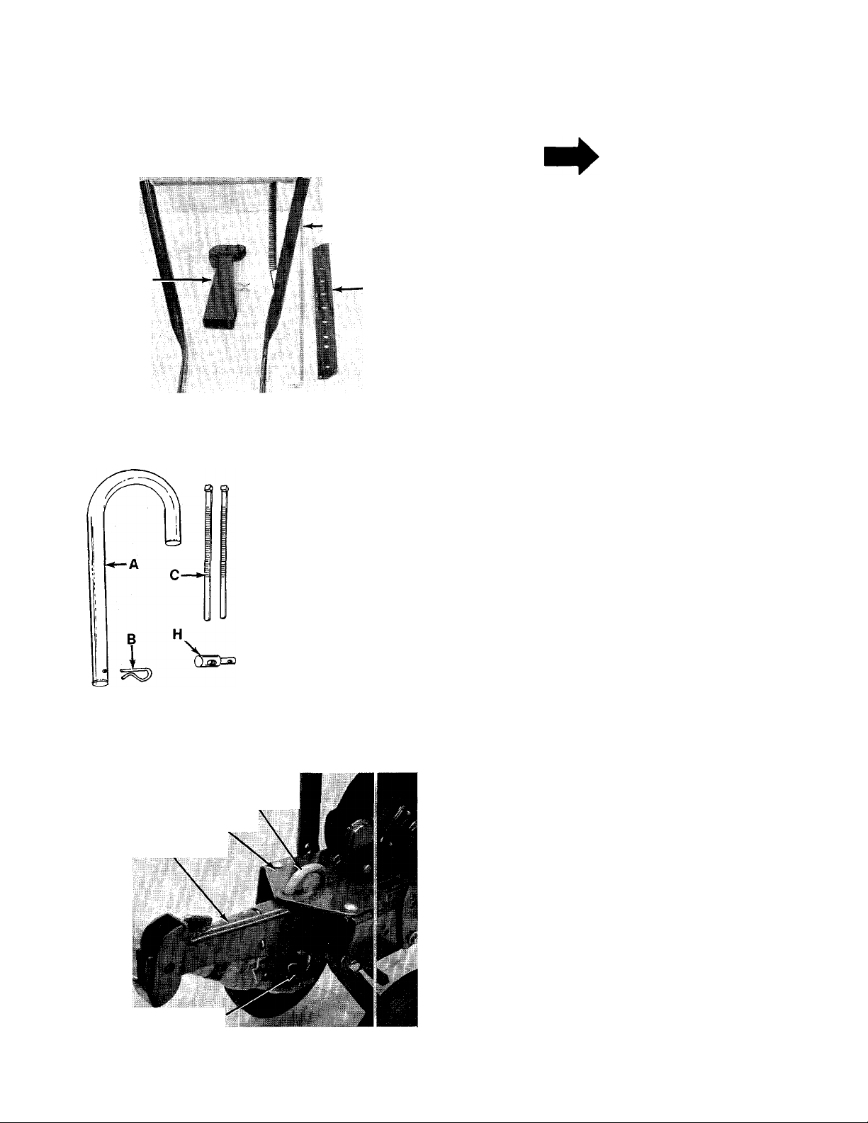
-Loose Parts in Carton: (See Figure 1)
Handle Panel Assembly
Depth Bar
Ta.lpiece
Control Rod
Hardware Pack (Not Shown)
-Contents of Hardware Pack: (See Figure 2)
A
(1) “U”-Clevis Pin .50" Dia.
(1) Internal Cotter Pin
B
(2) Cable Ties
C
D
(2) Hex Bolts 3/8-16 x 1.00" Lg.
E
(2) Belleville Washers 3/8" I.D.
F
(2) Lock Washers 3/8" I.D.
G
(2) Hex Nuts 3/8-16 Thd.
H
(1) Ferrule
I
(2) Hairpin Cotters
(1) Clevis Pin
K
L
(1) Spring Pin
M (2)
Carriage Bolts
Lock Washers 5/16" I.D.
N (2)
O (2)
Q
Hex Nuts 5/16-18 Thd.
P
(2) Clevis Pins (385 Only—Not Shown)
(2) Cotter Pins (385 Only—Not Shown)
Tailpiece
Cotter Pin (B)
FIGURE 3.
“U” Clevis
Pin (A)
Frame
TAILPIECE INSTALLATION
Slide the tailpiece into the frame. Secure with
-“U”-clevis pin (A) and cotter pin (B). See figure 3.
Page 5

Depth Bar
Spring
Pin (L)
FIGURE 4.
DEPTH BAR iNSTALLATiON
Slide the depth bar into the tailpiece to desired
depth. Secure with clevis pin (K) and spring pin (L).
■See figure 4.
HANDLE ASSEMBLY
1. Secure handle panel to handles by placing
carriage bolts (M) through the lower holes in
the handle panel and through the handles.
Secure with lock washers (N) and hex nuts (O),
finger tight only.
2. Remove hex bolt and belleville washer from
-----
each side of frame as shown in figure 5.
FIGURE 5.
Hex Bolt (D)
FIGURE 6.
3. Place the handle panel assembly in position
against the frame.
4. Start the hex bolt and belleville washer (re
moved in step 1) by hand in the bottom hole in
handle. See figure 6.
5. Select height position for the handle by lining
up one of the holes in the handle with desired
hole in frame. See figure 5.
6. Place belleville washer (E) on hex bolt (D), and
insert hex bolt through handle and frame.
Secure with lock washer (F) and hex nut (G) on
inside of frame. See figure 6.
7. Tighten all nuts and bolts securely.
NOTE
The clutch rod must be readjusted
whenever the handle height is
changed.
Page 6
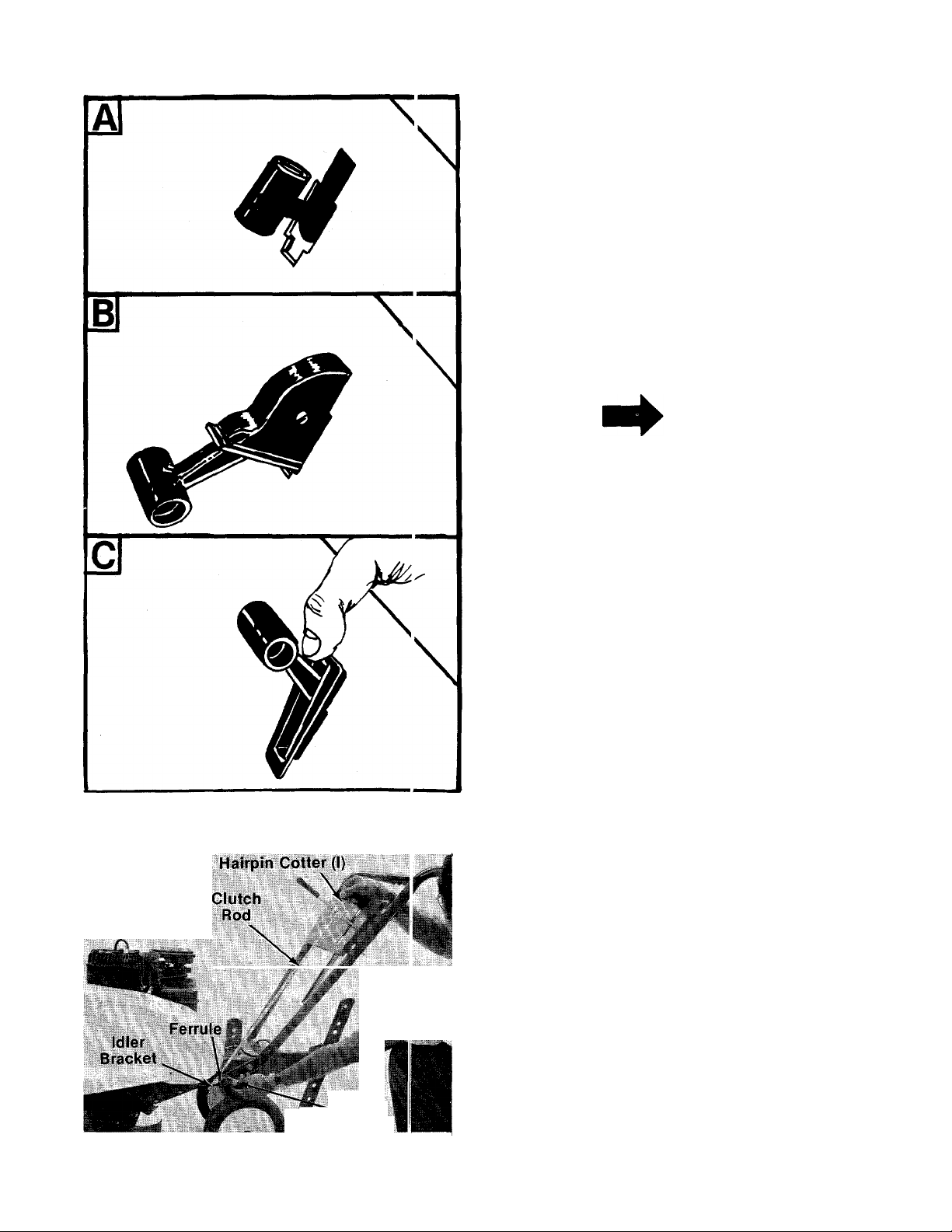
THROTTLE CONTROL ASSEMBLY
Assemble the throttle control to the handle panel
as follows.
, 1. Hold the throttle control assembly beneath
the handle panel. Turn the control sideways
and insert the lever up through the wide por
tion of the siot on the handle panel. See figure
------
7A.
After the end of the lever is through the slot,
turn and then tip the control forward as shown
-in figure 7B to slide it through the slot.
NOTE
The lever must be all the way to the
back of the control housing as
shown in figure 7B.
FIGURE 7.
3. Push the control back into the slot in the han
dle panel and press in place. Be certain the
—control is locked securely into the slot.
4. Secure throttle control cable to handle with
cable ties (C). Cut off excess ends.
CLUTCH CONTROL ROD INSTALLATION
1. Place shift lever (located on handle panel) in
neutral (N) position, Piace bent end of control
rod into shift lever. Secure with hairpin cotter
-----
(I). See figure 8.
2. Thread ferrule (H) onto the other end of con
trol rod so that the ferrule lines up with the
hole in idler bracket. Secure with hairpin cot
ter (I). See figure 8.
FIGURE 8.
K - Hairpin
Cotter (I)
Page 7
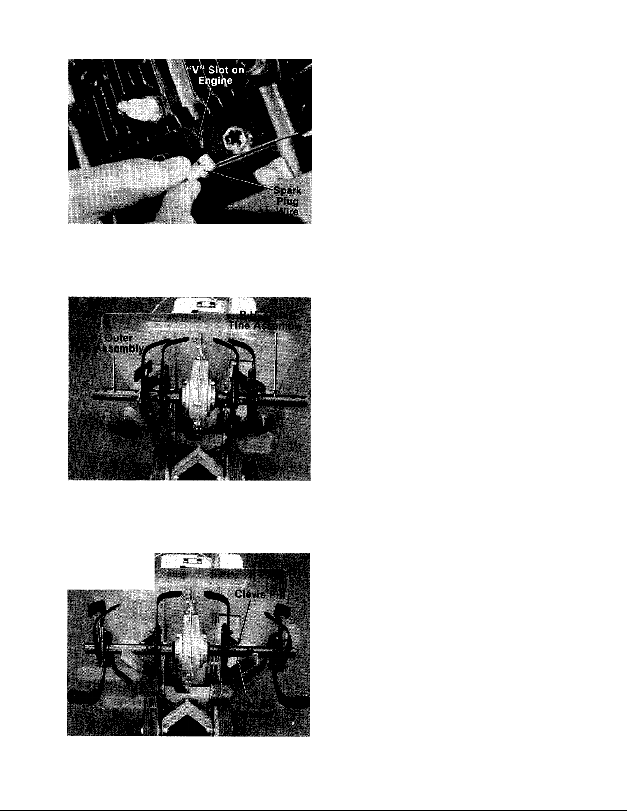
FIGURE 9.
3. Disconnect the spark plug wire from spark
plug to prevent accidental starting. Secure
end of spark plug wire in the “V” slot on the
— engine. See figure 9. With the clutch lever in
neutral position, pull starter cord several
times. The tines should not turn. If they do,
remove the hairpin cotter and remove the con
trol rod from the clutch lever. Thread the con
trol rod in or out of the ferrule as necessary.
Replace and check again for correct adjust
ment.
TINE ASSEMBLIES
Model 381 Only
Check to be certain the tine assemblies are on the
tine shaft so that the sharp edge enters the soil
first. See figure 11.
Model 385 Only
The inner tine assembiies are instaiied at the fac
tory. The outer tine assemblies are inverted. See
-figure 10. The right hand outer tine assembly has
been removed, inverted and slid onto the left hand
side for shipping only. The same has been done
with the left hand outer tine assembly.
FIGURE 10.
- J Ï-WÏW A ..W '*i
FIGURE 11.
Remove both outer tines. Place tine removed from
left hand side on right hand shaft. Place tine
removed from right hand side on left hand shaft.
Make sure that the sharp edge of the tines enters
the soil first. Secure with clevis pins (P) and inter-
■ nal cotter pins (Q). See figure 11.
Page 8

OPERATION
BEFORE STARTING ENGINE:
1. Before starting, fill crankcase with oil as in
structed in the separate engine manual
packed with the unit.
2. Fill fuel tank with clean, fresh, lead-free, low-
lead, or regular grade leaded gasoline.
NOTE
Warm engine does not require chok
ing.
Fill here,with gasoline
Starter Handle
FIGURE 12.
TO START ENGINE:
A
Be sure no one is standing in front
of the tiller while the engine is run
ning or being started.
Ilio
CAUTION
Oil nil
^ Oil Drain
FIGURE 14.
3.toMove throttle control lever forward
“START” position. See figure 13.
4. Stand at side of the tiller. Grasp the starter
handle and pull out rapidly. Return it slowly to
the engine. Repeat if necessary.
5. After engine starts, push choke knob in
gradually to “OFF” position.
1. Place the shift lever in the neutral (N) position.
See figure 13.
Throttle
Control
FIGURE 13.
2. Pull choke knob out to choke enginij. See
figure 14.
Shift 111
LevsrNj
TO STOP ENGINE:
1. Move throttle control lever to “STOP” posi
tion. See figure 13.
2. Remove spark plug wire from spark plug to
prevent accidental starting while equipment
is unattended.
HOW TO USE YOUR
TILLER
The tiller is a precision built machine designed for
seed bed preparation, cultivating, furrowing and
mulching. It Is engineered to minimize the hardest
work in the vegetable or flower garden, to till the
soil for planting and cultivating, and to perform
many other useful labor saving tasks in the
garden. With the proper amount of care and
maintenance, this machine will provide the owner
with many years of excellent service.
Page 9

WHEEL POSITION
The tiller is shipped with the wheels adjusted
such that the unit sits level. During digging as the
tines enter the ground and the front of the tiller
lowers, the wheels must be raised to level the
unit. This is essential for proper engine operation.
This adjustment is made by removing the clevis
pin and hairpin cotter from wheel yoke, raising the
wheels to the desired height, and replacing the
clevis pin and hairpin cotter. See figure 15.
^Hairpin ^
2. Depth Bar Adjustment: The depth bar acts as
a brake for the tiller and controls the depth
and speed at which the machine will operate.
See figure 17. Remove the clevis pin and
spring pin to raise or lower depth bar.
Wheel Setting
For Deep Digging
Shaiiow Dig
Fast Forward \
Deep Dig Siow
Forward
FiGURE 17.
Wheei Setting For
Shaiiow Digging
and/or Transport
FIGURE 15.
CONTROLLING SPEED AND TILLING DEPTH:
1. Wheel Yoke Adjustment: Place wheel yoke so
that the wheels are forward (nearest point be
tween wheels and tines) for shallow tilling,
cultivating and transport. This will increase
the forward speed. See figure 16. Turn yoke
around (farthest point between wheels and
tines) for deep tilling. Forward speed will
decrease. See figure 16.
By increasing the depth of the depth bar, the
forward speed of the machine is reduced, and
the working depth is increased. When the
depth bar is raised, the working depth of the
machine is reduced and the forward speed is
increased. The working depth of the machine
may be predetermined by setting the depth
bar and wheels so that the wheels are about
four inches from the ground when the tines
and depth bar are resting on the ground. This
setting will permit a working depth of about
four inches. Use maximum engine speed for
deep tilling. When presetting the working
depth, the handles should be a little above
waist height because the tiller will be lower
when the tines and depth bar penetrate the
ground. The best method will be determined
by the soil condition. In some soils, the
desired depth is obtained the first time over
the garden. In other soils, the desired depth is
obtained by going over the garden two or
three times. In the latter case, the depth bar
should be lowered before each succeeding
pass over the garden. Passes should be made
across the length and width of the garden
alternately. Rocks which are turned up should
be removed from the garden area.
Wheel Yoke in
this position
for deep dig.
FiGURE 16.
Wheei Yoke in this
position for shaiiow
dig, cuitivating and
transport.
3. Handle Pressure: Further control of tilling
depth and travel speed can be obtained by
variation of pressure on the handles. A
downward pressure on the handles will
reduce the working depth and increase the
Page 10

forward speed. An upward pressure ot the
handles will increase the working depti and
reduce the forward speed. The type of sciI and
working conditions will determine the cictual
setting of the depth bar and the handle
pressure required.
4. Throttle Control: The throttle control kver is
located on the right side of handle pan jI.
NOTE
Right hand side is determined from
the operator’s position standing be
hind the tiller.
The throttle control' lever adjusts the engine
speed. It also gives fingertip control of the car
buretor and magneto stop switch. With the throt
tle control knob pushed completely forward, the
carburetor is in “START” position. Pullirg the
throttle control back slightly adjusts the engine
speed to “FAST.” Pulling the throttle back further
reduces the engine speed to “SLOW.” Whnn the
throttle is pulled completely back, the megneto
stop switch grounds out the spark and sto 3s the
engine.
Use maximum engine speed for deep tilling Move
the throttle control to slow when transport! ig the
tiller. When the tiller is being moved to or frc m the
garden, the depth bar should be pivoted forward
until it engages the depth bar spring pin. The
machine may be moved under its own power,
without damaging grass areas as long an it is
allowed to move freely. If the operator holds back,
it will start to dig.
CULTIVATING
For cultivating, a two to three inch depth is
desirable. Setting the wheels and depth tiar so
that the wheels are about two inches abo'^e the
ground while the tiller is resting on the tine s and
depth bar will allow the machine to work at
cultivating depth. The throttle should be set to
control forward movement to a slow walking
speed. With standard tines, the working width of
the machine is 26 inches. For cultivation, this may
be reduced to 14 inches by removing the outer
tines. See figures 18 and 19.
FIGURE 18.
’iP5F-T="r.; :
................
, , . B.'-is"
SViL,',
FIGURE 19.
When laying out plant rows, be sure to allow
enough width to permit cultivation between the
rows. In growing corn or similar crops, check-row
planting will permit cross cultivation and prac
tically eliminate hand hoeing.
The tiller has many uses other than tilling and
cultivating a garden. One of these is the prepara
tion of lawn area for seeding. The tiller will
prepare a deep seed bed which will be free of hard
unfilled spots, allowing a better stand of grass to
grow. The tiller is very useful for loosening hard
soil for excavation with a shovel. No tedious hand
pickwork will be necessary. Your tiller may be
used for mixing compost in the pile, or for mixing
it with the soil in your garden. This should be done
after the soil has been broken to the full working
depth. The compost should be worked in to a
depth of six to eight inches. This may be done by
working the length of the garden, and then by mix
ing separate passes across its width. The addition
of decayed organic matter will substantially in
crease the fertility of your garden. For proper
decaying action, fertilizer should be applied and
10
Page 11

worked in with the mulch materials. Breaking up
leaves and straw and mixing it with several inches
of soil causes the soil to hold moisture longer and
allows proper aeration of the plant root system. It
also retards the growth of weeds.
The U.S. Department of Agriculture and various
state and local agencies offer published booklets
and expert advice on all phases of gardening.
They should be consulted regarding soil informa
tion, planting dates, and the most satisfactory
varieties of crop for your particular area.
CHAIN CASE
The chain case is pre-lubricated and sealed at the
factory. It requires no checking uniess the chain
case is disassembled. To fill with grease, lay the
left half of the chain case on its side, add 14
ounces of Plastilube #0 grease and assemble the
right half to it. This grease can be obtained at your
nearest authorized dealer.
MAINTENANCE
ADJUSTMENTS
WARNING i
Disconnect the spark plug wire and
ground against the engine before
performing any adjustments, repairs
or maintenance.
CLUTCH CONTROL ROD
To adjust the clutch control rod, refer to clutch
control rod installation, step number 3, under
Assembly Instructions.
WHEEL ADJUSTMENTS
To adjust the wheel yoke and wheel position, refer
to “How To Use Your Tiller” on page 8.
DEPTH BAR ADJUSTMENT
To adjust the depth bar, refer to “How To Use Your
Tiller” on page 8.
CARBURETOR ADJUSTMENT
warning {
If any adjustments are made to the
engine while the engine is running
(e.g. carburetor), disengage all
clutches and tines. Keep ciear of ali
moving parts. Be careful of heated
surfaces and muffler.
Do not make unnecessary adjustments. Factory
settings are correct for most applications. If ad
justments are needed, refer to the separate engine
manual packed with yourtilier.
I WARNING \
Disconnect the spark plug wire and
ground against the engine before
performing any adjustments, repairs
or maintenance.
ENGINEOIL
Check oil level every five operating hours. Make
sure oil level is maintained full to point of
overflowing.
Change the oil in the crankcase after the first two
hours of operation of your new engine and after
each 25 hours of use thereafter to insure proper
lubrication of internal parts. Take care to remove
dirt around filler plug. Refer to figure 12.
To change oil, remove drain plug while engine is
warm and tip the tiller forward. Replace drain plug.
Remove oil filler cap and refill with new oil of pro
per grade. Replace filler cap.
AIR CLEANER
The air cleaner prevents damaging dirt, dust, etc.
from entering the carburetor and being forced into
the engine and is important to engine life and per
formance.
To service air cleaner, refer to the separate engine
manual packed with your unit.
Never run your engine without air cieaner com
pletely assembled.
CLEAN ENGINE
This is an air-cooled engine which operates most
efficiently when the cooling fins are clean.
Clean cylinder fins and underside of tank or hous
ing thoroughly of all accumulated grass and
debris.
LUBRICATION
IMPORTANT
Always stop engine and disconnect
spark plug wire before cieaning,
lubricating or doing any kind of
work on tiller.
SPARK PLUG
The spark plug should be cleaned and the gap
reset at least once a season or when oil is
changed. Spark plug replacement is recom
mended at the start of each mowing season;
check engine manual for correct plug type and
gap specification.
11
Page 12

BELT REPLACEMENT
Your tiller has been engineered with belts nru de of
special material (Kevlar Tensile). Replacement
should not be made with an off-the-shelf be t.
If belt replacement is required, order belt or belts
by part number from , your nearest authorized
dealer.
Forward Drive Belt—Part No. 754-0154 V2" x 3'"' Lg.
Reverse Drive Belt—Part No. 754-0201 V2" x 4 I" Lg.
Removing and Replacing the Forward Drive Belt.
1. Remove the belt guard, by removing fcur (4)
hex self-tapping screws.
2. Press down on the left side of the tine £ hield
and slip off the belt guard. See figure 2(1.
FIGURE 21.
4. Pull the shift lever back into reverse (R) posi
tion. Lift the forward drive belt off the engine
pulley, flat idler and chain case pulley. See
figure 22.
i.
Belt Guard
Left Side of Tine Shield
FIGURE 20.
3. Loosen (do not remove) the hex screw a id nut
holding the belt retainer, using two 7/16"
wrenches. See figure 21.
CAUTION
When reassembling the belt, be
certain to secure the belt retainer
against the tab on the clutch mount
ing plate. Incorrect placement of
the belt retainer can cause ex
cessive wear on the belt.
FIGURE 22.
Reassemble the new belt with the “V” side of belt
to the inside. Assemble in reverse order.
Removing and Replacing the Reverse Drive Belt.
1. To remove the reverse drive belt, you must
remove the forward drive belt first. See remov
ing the forward drive belt section, steps 1,2, 3
and 4.
2. With the shift lever in neutral (N) position, slip
the reverse drive belt off the chain case pulley
and “V”-Groove of engine pulley. See figure
23.
12
Page 13

Reverse
Drive Belt
Flat ldl{ ______
Pulley , Cha№C!ase Pulley
FIGURE 23,
Place the shift lever in reverse (R) position.
3.
Remove hex lock nut holding the flat reverse
idler pulley. See figure 23. Puli the idler
bracket forward with one hand. Slip off flat
idler and belt together. See figure 24.
FIGURE 25.
OFF SEASON STORAGE
FIGURE 24.
4. When reassembling new reverse drive belt,
make sure the V-portion of belt is to the out
side and flat side is to the inside. Loop one
end of belt over flat idler pulley and place flat
idler pulley and belt back in position on idler
bracket. Secure idler pulley with hex lock nut.
NOTE
Fiat idler pulley must be installed
with the sleeve side towards the
idler bracket. See figure 25.
If the tiller is not to be used for a while, the follow
ing procedure should be followed. The tines,
depth bar, gear case and wheels should be
cleaned of all dirt. It is very important that the unit
be stored in a level position to prevent engine oil
from draining into the cylinder head cavity.
Engines on tillers to be stored between seasons
should be completely drained of fuel to prevent
gum deposits forming on essential carburetor
parts, and fuel tank.
(a) All fuel should be removed from fuel tank.
Run the engine until it stops from lack of fuel.
The small amount of fuel that remains in the
sijimp of the tank should then be removed by
absorbing it with a clean dry cloth.
(b) Clean dirt and chaff from cylinder, cylinder
head fins and blower housing.
(c) Remove spark plug, pour 2 or 3 tablespoons
of SAE-30 oil into cylinder and puil crank cord
out slowiy to distribute oil. Replace spark
plug.
Just as your automobile needs professional
mechanical maintenance from time to time, so
does your air-cooled engine. Cleaning and ad
justing of the carburetor and periodic replacement
of the spark plug and ignition points is made
necessary by NORMAL use.
Professional Air-Cooled Engine Service is as
close as your telephone book.
13
Page 14

A yearly checkup or tune-up by an authcrized
engine dealer is a good idea to avoid breakdawns
or delay.. .do it at the end of the season, then
you’re ready for the next.
Replace any remaining fuel on hand or in the
engine fuel tank with a fresh supply of winter
grade fuel. Winter fuels contain additives for
faster starts. Keep fuel tank full.
A
When storing any type of power
equipment in an unventilated or
metal storage shed, care should be
taken to rust proof the equipment.
Using a light oil or silicone, coat the
equipment, especially any springs,
bearings and cables.
TILLER WINTERIZING INSTRUCTIONS FOF USE
WITH SNOW BLADE:
1. For cold weather (below 32°F.), drain oil from
tiller engine crankcase and replace with SAE
low or 10W-20 detergent oil.
CAUTION
TROUBLE SHOOTING CHART
NOTE
It may be necessary to enrich the
carburetor idle and high speed jets
1/8 to Va turn (counterclockwise) for
good performance.
3. In the spring of the year, before the tilling
season, be sure to change engine oil back to
SAE 30W detergent oil.
SYMPTOM POSSIBLE CAUSE(S)
Engine fails to start
Hard starting or loss of
power
Engine overheats
Tine control does not
engage
1. Check ’uel tank for gas.
2. Spark plug lead wire
disconnected.
3. Faulty spark plug.
1. Spark plug wire loose.
2. Dirty a r cleaner.
1. Carburstor not adjusted
properly.
2. Air flow restricted.
3. Engine oil level low.
Belt worr and/or
stretched.
SOLUTION
1. Fill tank if empty.
2. Connect lead wire.
3. Spark should jump gap between
control electrode and side elec
trode. If spark does not jump,
replace the spark plug.
1. Connect and tighten spark plug
wire.
2. Clean air cleaner as described in
engine manual.
1. Adjust carburetor. See engine
manual.
2. Remove blower housing and clean
as described in the engine
manual.
3. Fill crankcase with the proper oil.
Make control rod adjustment (see
Assembly Instructions) or replace
belt.
NOTE: For repairs beyond the minor adjustments listed above, please contact your local service dealer.
14
Page 15

NOTES
15
Page 16

Models 381 and 3Ci5
30 \ 27
29
16
Page 17

Models 381 and 385
PARTS LIST FOR MODEL 381 AND 385 TILLERS
REF.
PART
NO.
NO.
1 746-0503
784-0034
2
3 720-0180
4
710-0458
COLOR
CODE
DESCRIPTION
Throttle Control Wire—35"
Handle Panel Ass’yHandle Grip
Carriage Bolt 5/16-18 x 1.75"
Lg.*
5 714-0149
6 04602
7
710-0451
Internal Cotter Pin 30 712-0200
“U”-Clevis Pin .500" Dia. 31 06813
Carriage Bolt 5/16-18 x .75"
Lg.*
04586
8
9 711-0231
10 04668
11 732-0194
12 732-0290
13 736-0119
14
714-0145
15 736-0119
16 712-0267
17
749-0502
18 736-0105
19 710-0253
20 710-0118
736-0169
21
22
712-0798
23 736-0253
—463 Depth Bar 1.00" Lg.*
“U’’-Channel Plate 33
Clevis Pin .500" Dia.
Spring Pin 35 06794
Depth Bar Spring
L-Wash. 5/16" I.D.* 36 749-0356
Internal Cotter Pin 37 711-0599
L-Wash. 5/16" I.D.* 38 736-0119
Hex Nut 5/16-18 Thd.*
Handle—LH. 40
Belleville Wash. 3/8" I.D.
Hex Bolt 3/8-16 X 1.00" Lg.*
Hex Bolt 5/16-18 X .75" Lg.* 43 747-0183
L-Wash. 3/8" I.D.* 44
Hex Nut 3/8-16 Thd.* 45 720-0143
Belleville Wash. .505 I.D. x 46 831-0692
1.00" O.D. 47
24
741-0116
FI. Bearing w/Flats .631 I.D.
(385 Only)
25 734-0968 Wheel Ass’y. 9 x 1.75 (381)
734-0584 Wheel Ass’y. Comp. 10 x 50 732-0191
1.75 (385)
REF.
NEW
PART
NO.
26 738-0318
N
27 712-0267
28 736-0119
29
32
34
39 712-0267
41
42
48 736-0159
49 712-0158
PART
NO.
736-0921
06792
712-0267
710-0322
06816
712-0267
04589
747-0182
735-0126
COLOR
CODE
-463
DESCRIPTION
Shoulder Bolt .625" Dia. x
2.75" Lg.
Hex Nut 5/16-18 Thd.*
L-Wash. 5/16" I.D.*
L-Wash. Va" I.D.*
Hex Inst. L-Nut V2-20 Thd.
Wheel Bracket Ass’y.
Engine “U”-Channel
Ass’y.—L.H.
Hex Nut 5/16-18 Thd.*
Hex Sems Bolt 5/16-18 x
Engine “U”-Channel
Ass’y.—R.H.
Handle—R.H.
Clevis Pin
L-Wash. 5/16" I.D.*
Hex Nut 5/16-18 Thd.*
“U”-Channel Bracket Ass’y.
Hex Nut 5/16-18 Thd.*
Tailpiece Ass’y.
Control Rod
Clutch Lever
Grip
Throttle Control Box Ass’y.
Rubber Wash.
FI-Wash. .344" I.D. x
.880 O.D. X .06
Hex Cent. L-Nut 5/16-18 Thd.
Extension Spring .75" O.D.
X 11.0" Lg.
NEW
PART
N
'For faster service obtain standard nuts, bolts, and washers iocaliy. If these items cannot be obtained
locally, order by part number and size as shown on parts iist.
(463—Top Fiite Red) When ordering parts if color or finish is important, use the appropriate color
(447—Patina Silver) code shown at left. (e.g. Top Fllte Red Finish—15278 (463).)
The engine is not under warranty by the tiller manufacturer. If repairs or service is needed on the
engine, please contact your nearest authorized engine service outlet. Check the “Yellow Pages” of
your telephone book under “Engines—Gasoline.”
NOTE
This instruction manual covers various models
and all specifications shown do not necessari
ly apply to your model. Specifications subject
to change without notice or obligation.
17
Find It Fast
In The
Yellow Pages
Page 18

Models 381 and 385
29
Page 19

Models 381 and 385
PARTS LIST FOR U ODE L 381 AND 385 TILLERS
REF.
NO.
10 747-0180 Control Rod 40
11 06786
12
13
14
15
16 712-0195
17 711-0392 Ferrule
18 714-0145
19
20 756-0225 Fl-ldler w/Flanges 3.12 O.D.
21 06803
22 710-0121 Hex Bolt 1/2-20 X .75 Spec.
23 747-0181
24 736-0114 Internal L-Wash. 1/2" I.D.
25 736-0463
26 714-0133
27
28 736-0258
29 736-0169
30 710-0191 Hex Bolt 3/8-24 x 1.25" Lg.*
31 750-0229
PART
1
712-0287
2
3 736-0329
4 06801
710-0252
5
6 06796 —447
7 710-0599
NO.
_
COLOR
CODE
DESCRIPTION
Engine
Hex Nut 1/4-20 Thd.*
L-Wash. 1/4" I.D.*
Support Bracket
Hex Bolt 1/4-20 X .75" Lg.*
Belt Guard
Thread Rolling Scr. V4-20 x
.50" Lg. 36 736-0170 Shake-Proof Wash.
8 712-0185
738-0281
9
“U”-Type Speed Nut
Shoulder Bolt .625" Dia. x
.170" Lg. (2 Req’d.)
Reverse Idler Brkt. Ass’y732-0433
06784
712-0375
Spring —Idler Brkt.
Forward Idler Brkt. Ass’y- 42 710-0600 Hex Wash. Hd. Self-Tap Scr.
Hex Cent. L-Nut 3/8-16 Thd.
(2 Req’d.) 43 710-0191
747-0183
Clutch Control Rod
Speed Nut 3/8-24 Thd. 44
Inter. Cotter Pin
712-0262 Hex Jam Nut 3/8-24 Thd.
(2 Req’d.)
X .75 (2 Req’d.)
Clutch Mounting Plate
Belt Guard Rod
FI-Wash. 1/4" I.D.
Sq. Key 3/16" x 1.50" Lg.*
756-0261
Engine Pulley
FI-Wash. 3/8" I.D. x 1.00"
L-Wash 3/8" I.D.*
Spacer .635 I.D. x .88 O.D.
X 1.035 Lg.
NEW
PART
REF.
NO.
32 754-0201
PART 1 COLOR
NO. 1 CODE
DESCRIPTION
“V”-Belt 1/2" X 41" Lg.
Reverse
754-0154 “V”-Belt 1/2" X 37" Lg.
33
Forward
34 756-0262
35 710-0573
Chain Case Pulley 6.0" Dia.
Hex Bolt 5/16-18 X 1.25" Lg.
Special
37 736-0231 FI-Wash. 5/16" I.D. X 1.120
38 714-0149
Internal Cotter Pin 1/2" Dia.
39 742-0209 Tine Blade—LH. (381)
742-0210 Tine Blade—R.H. (381)
41 15697
Inner Tine Adapter Ass’y.
(381)
5/16-18 x .50" Lg. (381)
Hex Bolt 3/8-24 x 1.25" Lg.
(385)
712-0241
45 06798
Hex Nut 3/8-24 Thd.* (385)
Inner Tine Adapter Ass’y.
(385)
712-0267
46
47
742-0107
Hex Nut 5/16-18 Thd.*
Tine—LH. (385)
48 742-0108 Tine—R.H. (385)
49 04598 Tine Shield
50 710-0442
Hex Bolt 5/16-18 X 1.50" Lg.*
51 15380 Outer Tine Adapter Ass’y.
(381)
53 1545-029
711-0599
54
04683
Clevis Pin (381)
Clevis Pin (385)
Outer Tine Adapter Ass’y.
(385)
55 736-0175
736-0170
56
57 710-0118
Bell-Wash.
Shake-Proof Wash.
Hex Bolt 5/16-18 X .75" Lg.*
NEW
PART
*For faster service obtain standard nuts, bolts, and washers locally. If these items cannot be obtained
locally, order by part number and size as shown on parts list.
TINE CHART
Model 381
Part No.
15696
15378
15695
15377
Model 385
Part No.
Description
06818 Inner Tine Ass’y. Comp.—R.H.
04290 Outer Tine Ass’y. Comp.—R.H.
06819 Inner Tine Ass’y. Comp.—L.H.
04289
Outer Tine Ass’y. Comp.—L.H.
19
Page 20

Model 381
Chain Case Assembly 15282
ULU
28 1011 5 PS
NOTE: Use 14 ounces of
Plastilube #0.
Order Part No. 737-0133
REF.
NO.
PART
NO.
COLOR
CODE
1 750-0315
738-0182
2
721-0132
3
15276
4
741-0155
5
05034
6
750-0229
7
756-0262
8
710-0643
9
10 736-0119
736-0231
11
710-0599
12
712-0267
14
710-0644
15
731-0374
16
736-0163
19
750-0314
20
15273
21
710-0599
22
721-0175
23
PARTS LIST FOR CHAIN CASE 15282 (MODEL 381 TILLER)
DESCRIPTION
Spacer .657" I.D. x .78" O.D.
X 2.19" Lg.
Jackshaft
Housing Gasket
NEW
PART
REF.
NO.
24
25
26
27
PART 1 COLOR
NO. 1 CODE
731-0487
712-0798
736-0169
710-0322
Housing Ass’y.—L.H. Hall
710-0538
Ball Bearing .625" I.D. x
28
1.375" O.D.
15274
Bearing Housing
Spacer .635" I.D. x .88" O.D.
X 1.03" Lg.
Chain Case Pulley 6.0" Dij.
29
30
31
32
748-0229
713-0206
713-0131
Hex Bolt 5/16-18 X 1.0" Lg,
713-0186
(Special)
33
L-Wash. 5/16" I.D.*
748-0855
FI-Wash. .344" I.D. x 1.125"
O.D.
34
35
713-0187
Hex Wash. Hd. Self-Tap S:r.
738-0320
1/4-20 X .50" Lg.
Hex Nut 5/16-18 Thd.*
36
37
713-0182
Hex Bolt 3/8-16 X 3.25" Lg.*
713-0181
Flange Bearing (Plastic)
Flat Thrust Wash.
Step Spacer
38
39
40
738-0308
715-0114
Tine Shaft Ass’y-
714-0133
Hex Wash. Hd. Self-Tap Scr.
41
1/4-20 X .50" Lg.
Seal Ring
20
DESCRIPTION
Dust Cap
Hex Nut 3/8-16 Thd.*
L-Wash. 3/8" I.D.*
Hex Sems Bolt 5/16-18 x
1.00" Lg.*
Hex Bolt 5/16-18 X .62" Lg.
(Special)
Housing Ass’y.—R.H. Half
Hex Flange Bearing
Sprocket 10 Tooth Vz" Pitch
#41 Chain Vz" Pitch x 34
Links
#420 Chain Vz" Pitch x 48
Links
Flange Bearing .625" I.D.
#50 Chain 5/8" Pitch x 28
Links
Sprocket Shaft
Sprocket Bearing Sleeve
Ass’y.
Sprocket Sleeve Ass’y.
Sprocket Shaft
Spring Pin Spiral V4" Dia.
X 1.50" Lg.
Square Key 3/16 x 3/16 x
1.50" Lg.*
NEW
PART
Page 21

750-0315
1
2
721-0132
3
4
06926
5
6
PART
NO.
738-0182
741-0155
05034
REF.
NO.
7 750-0229
756-0262
8
710-0643
9
10 736-0119
11 736-0231
710-0599
12
14 712-0267
710-0644
15
16 721-0102
19 736-0259
750-0314
20
21 06800
710-0599
22
COLOR
CODE
NEW
DESCRIPTION
Spacer .657 I.D. x .78 O.D.
X 2.19
Jack Shaft
Gasket for Housing
REF.
PART
NO.
23 721-0133
24 741-0198
25 712-0798 Hex Nut 3/8-16 Thd.*
26 736-0169
Housing Half—LH. 27
Ball Bearing .625 I.D. x
1.375 O.D.
28 710-0538 Hex Bolt 5/16-18 X .62"
Bearing Housing
Spacer .625 I.D. x .88 O.D.
x 1.035
29
30 748-0229 Hex Flanged Bearing .630
Chain Case Pulley 6.00"
PART
NO.
COLOR
CODE
DESCRIPTION
Gasket for Bearing Hsg.
Bearing Housing Ass’y.
L-Wash. 3/8" Scr.*
710-0322 Hex Sems Bolt 5/16-18 x
1.00" Lg.*
Lg. Special
06923 Housing Half—R.H.
I.D.
Dia. 31 713-0206 Sprocket 10 Teeth x .500
Hex Bolt 5/16-18 X 1.00"
Lg. Special
L-Wash. 5/16" Scr.*
FI-Wash. 5/16 I.D. x 1.125
713-0131 #41 Chain Уг" Pitch x 34
32
713-0186
33
Pitch
Links—Endless
#420 Chain Vz” Pitch x 48
O.D. X .125 Links—Endless
Hex Self-Tap Scr. V4-20 x 34
.50" Lg.
Hex Nut 5/16-18 Thd.*
Hex Bolt 3/8-16 X 3.25" Lg.
Oil Seal 1" I.D. x 1.357 O.D.
FI-Wash. 1.0" I.D. x 1.62
O.D. X .090
Spacer 1.0" I.D. x 2.0" O.D.
X .68
Tine Shaft Ass’y.
Hex Self-Tap Scr. 1/4-20 x
748-0855 Flange Bearing .626 I.D.
713-0187
35
#50 Chain 5/8" Pitch x 28
Links—Endless
36 738-0320 Sprocket Shaft
37 713-0182
Sprocket Bearing Sleeve
Ass’y.
38 713-0181 Sprocket Sleeve Ass’y.
39 738-0308 Sprocket Shaft
715-0114
40
Spring Pin Spiral V4" Dia.
X 1.5" Lg.
41 714-0133 Sq. Key 3/16 x 1.50" Lg.
.50" Lg.*
21
NEW
PARI
Page 22

Heavy Duty Garden Tiller Attachments Available for Ail-Season Use
31-0106 Depth Gauge Wheels (Pair)
31-0107 6-Tine Cultivator (Must be used vi ith
31-0106 Depth Gauge Wheels)
31-0110 8" Furrower Opener
31-0111 15" Sweep Cultivator
31-0113 Pneumatic Tires, 13 x 5.00-6 (Pair;
31-0114 Wheel Weights (Pair)
31-0115 Tire Chains, 13 x 5.00 (2 Link) (Pair)
31-0116 32" Leveling/Snow Blade (385 Onl/)
31-0119 Tine Cultivating Shields w/Adapters
(Pair)
Note; Attachments are availalile through your local dealer or from the factory:
Agri-Fab Inc., 303 W. Raymoid Street, Sullivan, Illinois 61951 (217) 728-4334
31-0123 Lawn Aerator (Use with 31-0114 Wheel
Weights for added penetration)
31-0144 “V”-Bar Cultivating Kit
Kit Includes: “V”-Bar Frame, 4-Point
Cultivating Tines, Hiller/Furrower,
Depth Gauge Wheels (Pair).
31-0145 Depth Stake Cultivating Kit
Kit Includes; 8" Furrower Opener, 15"
Sweep Cultivator, 32" Leveling Rake,
Extra Depth Stake.
22
Page 23

parts; information
POWER EQUIPMENT PARTS AND SERVICE
Parts and service are available through the authorized s jrvice
firms listed below. All orders should specify the model num ser of
your unit, part numbers, description of parts and the quan ity of
each part required.
NOTE: If any parts are found to be missing or d sfective upon assembly of this unit, write to advise the factory so
that immediate replacement can be mads.
ALABAMA BIRMINGHAM
Auto Electric & Carburetor Co. ... 2625 4th Ave.S
ARKANSAS NORTH LITTLE ROCK
Sutton's Lawn Mower Shop
CALIFORNIA PORTERVILLE
Billious
COLORADO DENVER
FLORIDA JACKSONVILLE
GEORGIA EAST POINT
ILLINOIS LYONS
INDIANA ELKHART
IOWA DUBUQUE
LOUISIANA new ORLEANS
MARYLAND TAKOMA PARK
MASSACHUSETTS SPRINGFIELD
MICHIGAN LANSING
MINNESOTA HOPKINS
MISSISSIPPI BILOXI
MISSOURI KANSAS CITY
NEW JERSEY BELLMAWR
NEW MEXICO ALBUQUERQUE
NEW YORK CARTHAGE
...............................................
Spitzer Industrial Products Co. . . . 6601 N.
Radco Distributors............................. 4909 Victor St.
Small Eng. Dist
East Point Cycle & Key
Keen Edge Co
Parts & Sales Inc
Power Lawn & Garden Equip
Suhren Engine Co............................. 8330 Earhart Blvd
Center Supply Co
Morton B. Collins Co
Lorenz Service Co
Power Equipment Dist
Hance Distributing Inc
Biloxi Sales & Service, Inc................. 506 Caillavet St...............3S533
Automotive Equip. Service
Ross-Frazier Supply Co
Henzier, Inc
Lawnmower Parts Inc........................717 Creek Rd...................0£030
Spitzer Eng. & Parts
Gamble Dist., Inc
..................................
...................................
....................................
...............................
.............................
...........................................
...............................
...............
.....................
............
.........................
.......................
...........................
...............
....................
..........................
5301 Roundtop Drive
Box368, Rt. 4
75 North D Street
Washington St
Box 5459
OPA LOCKA
2351 N.W. 147th St. .. .33054
2834 Church St
8615 Ogden Ave
2101 Industrial Pkwy.. .45516
2551 J.F. Kennedy . . . .5 5001
6867 New Hampshire
Ave
300 Birnie Ave
2500 S. Pennsylvania . .4 1910
MOUNT CLEMENS
340 Hubbard
420 Excelsior Ave. W. .55343
3117HolmesSt
ST. JOSEPH
8th and Monterey
ST. LOUIS
2015 Lemay Ferry Rd. .63125
1023 Third Ave. N.W. ..87103
West End Ave
....................
.................
.............
...............
.....................
...............
..............
...........
...............................
................
...................
.................
.............
..................
S5233
'2117
03257
10229
G2207
3 3344
63534
7 0118
23912
01107
.43043
6‘ 109
O'i 503
13 519
BRIGGS AND STRATTON, TECUMSEH AND PEERLESS PARTS
AND SERVICE
Briggs & Stratton, Tecumseh and Peerless parts and servicr
should be handled by your nearest authorized engine service firm.
Check the yellow pages of your telephone directory under the
listing Engines—Gasoline, Briggs & Stratton or Tecumseh
Lauson.
NORTH CAROLINA GOLDSBORO
Smith Hardware Co............................515 N. George St
Dixie Sales Company
OHIO CARROLL
Stebe’s Mid-State Mower Supply . Box 366, 71 High St.. . .43112
Bleckrie, Inc....................................... 7900 Lorain Ave..
National Central................................. 687 Seville Rd. ..
Burton Supply Co
OKLAHOMA MUSKOGEE
Victory Motors, Inc
OREGON PORTLAND
Kenton Supply Co
PENNSYLVANIA HARRISBURG
EECOInc
Thompson Rubber Co........................ 5222-24 N. Fifth St
Bluemont Co......................................11125 Frankstown Rd.. 15235
Frank Roberts & Sons
Scranton Auto Ignition Co............... 1133-35 Wyoming Ave. 18509
TENNESSEE KNOXVILLE
Master Repair Service
American Sales & Service, Inc. . . . 3035-43 Bellbrook .... 38116
TEXAS DALLAS
Marr Brothers, Inc
Woodson Sales Corp
Bullard Supply Co.............................. 2409 Commerce St. ... 77003
Engine House Inc
UTAH SALT LAKE CITY
A-1 Engine & Mower Co
VIRGINIA ASHLAND
RBI Corp............................................101 Cedar Ridge Dr. . . .23005
WASHINGTON SEATTLE
Bailey’s Inc
WISCONSIN APPLETON
Automotive Supply Co
Horst Dist
............................................
..........
...........................................
........................
..............................
.............................
.............................
......................
......................
..............................
.........................
..............................
....................
..............................
....................
GREENSBORO
335 N. Green
CLEVELAND
WADSWORTH
YOUNGSTOWN
1301 Logan Ave.
Box 929
605 S. Cherokee
8216 N. Denver Ave. . . .97217
4021 N.6thSt..................17110
PHILADELPHIA
PITTSBURGH
PUNXSUTAWNEY
R.D. 2
..............................
SCRANTON
2000 Western Ave
MEMPHIS
423 E. Jefferson
FORT WORTH
1702 N. Sylvania
HOUSTON
SAN ANTONIO
8610 Botts Lane
P.O. Box 17867
439 E. 900 So
1414 14th Ave
123 S. Linwood Ave.
P.O. Box 798
CHILTON
444 N. Madison
.............
..................
.........................
...........
........
.........
............
...........
..............
...............
.................
.................
.............
27530
27402
.44102
.44281
44501
74401
19120
15767
37921
75203
76111
78217
84111
98122
54911
53014
WARRANTY P\RTS AND SERVICE POLICY (0783)
The purpose of warranty is to protect the customer from d(
time of manufacture. It does not provide for the unlimited i
sibility of the customer. The manufacturer cannot assume
the manufacturer’s fault, it’s the manufacturer’s responsibi
CLAIMS AGAINST THE MANUFACTURER’S WARRANTY
INCLUDES:
1. Replacement of Missing Parts on new equipment.
2. Replacement of Defective Parts within the warranty per
3. Repair of Defects within the warranty period.
MTD PRODUCTS INC •
itects in workmanship and materials, defects which are NOT detected at the
ind unrestricted replacement of parts. Use and maintenance are the responresponsibility for conditions over which it has no control. Simply put, if it’s
ity; if it’s the customer’s fault, it’s the customers’s responsibility.
All claims MUST be substantiated with the following
information:
1. Model Number of unit involved.
od.
30X 36900
2. Date unit was purchased or first put into service.
3. Date of failure.
4. Nature of failure.
CLEVELAND, OHIO 44136
 Loading...