

Page 1

OWNERS
MANUAL
.75
CHAIN
DRIVE
ASSEMBLY
OPERATION
MAINTENANCE
PARTS LIST
Important:
TILLER
Model Number
214-031-000
Read Safety Rules and
Instructions Carefully
PRINTED IN U.S.A.
Thank you for purchasing an
American built product.
FORM NO. 770-3197
Page 2

INDEX
Safe Operation Practices........................................3
Assembiy Instructions.......................................... 4
Operation
Adjustments.............................................................8
Lubrication.............................................................10
Maintenance ..........................................................10
.................................................................
r
LIMITED WARRANTY
♦
♦
♦
♦
♦
♦
♦
♦
For one year from the date of oric inal retail purchase, MTD PRODUCTS INC will either
repair or replace, at its option, free 3f charge, F.O.B. factory or authorized service firm, any
part or parts found to be defective n material or workmanship. Transportation charges for
the movement of any power equipn ent unit or attachment are the responsibility of the pur
chaser. Transportation charges for any parts submitted for replacement under this warran
ty must be paid by the purchaser ur less such return is requested by MTD PRODUCTS INC.
This warranty will not apply to any part which has become inoperative due to misuse, ex
cessive use, accident, neglect, improper maintenance, alterations, or unless the unit has
been operated and maintained in accordance with the instructions furnished. This warran
ty does not apply to the engine, mo tor, battery, battery chargeror component parts thereof.
Please refer to the applicable manufacturer’s warranty on these items.
Off-Season Storage
Troubie Shooting Chart
7
Parts for Chain Case.............................................13
Iliustrated Parts
Parts List ...............................................................15
Parts Information
..............................................
........................................
.....................................................
....................................
Back Cover
11
12
14
♦
♦
♦
♦
♦
♦
♦
\
♦
♦
♦
♦
♦
♦
This warranty will not apply where the unit has been used commercially.
Warranty service is available through your local authorized service dealer or distributor. If
you do not know the dealer or distributor in your area, please write to the Customer Service
Department of MTD.
The return of a complete unit will not be accepted by the factory unless prior written per
mission has been extended by MTD.
This warranty gives you specific legal rights. You may also have other rights which vary
from state to state.
V
This unit is equipped with an internal combustion engine and should not be used on or near any unim
proved forest-covered, brush-covered or grass-covered land unless the engine’s exhaust system is
equipped with a spark arrester meeting ap plicable local or state laws (if any). If a spark arrester is used, it
should be maintained in effective working order by the operator.
♦
♦
♦
♦
♦
♦
In the State of California the above is rec|uired by law (Section 4442 of the California Public Resources
Code). Other states may have similar laws Federal laws apply on federal lands. A spark arrester muffler is
available at your nearest engine authorized service center.
Page 3

J WARNING I
To reduce the potential for any injury, comply with the following safety instructions. Failure to comply with
the instructions may result in personal injury.
SAFE OPERATION PRACTICES FOR TILLERS
1. It is suggested that this manual be read in its
entirety before attempting to assembie or
operate this unit. Keep this manual in a safe
place for future reference and for ordering
replacement parts.
2. Your tiller is a precision piece of power equip
ment, not a plaything. Therefore, exercise ex
treme caution at all times.
3. Read this Owner’s Manual carefully. Be
thoroughly familiar with the controls and the
proper use of the equipment.
4. Never aliow children to operate a power tiller.
Only persons well acquainted with these rules
of safe operation should be allowed to use
your tiller.
5. Keep the area of operation clear of all per
sons, particularly small children and pets.
6. Do not operate equipment when barefoot or
wearing open sandals. Always wear substan
tial footwear.
7. Do not wear loose fitting clothing that could
get caught on the tiller.
8. Do not start the engine unless the shift lever
is in the neutral (N) position.
9. Do not stand in front of the tiller while starting
the engine.
10. Do not place, feet and hands on or near the
tines ’When starting the en'gine or while the
engine is running.
11. Never attempt to make a wheel or depth bar
adjustment while the engine is running.
14. Check the fuel before starting the engine.
Gasoline is an extremely flammable fuel. Do
not fill gasoline tank indoors, when the engine
is running, or whiie the engine is stiil hot.
Wipe off any spilled gasoline before starting
the engine as it may cause a fire or expiosion.
15. Do not run the engine while indoors. Exhaust
gases are deadly poisonous.
16. Be careful not to touch the muffler after the
engine has been running, it is hot.
17. Do not change the engine governor settings
or overspeed the engine. Excessive engine
speeds are dangerous.
18. Before any maintenance work is performed or
adjustments are made, remove the spark plug
wire and ground it on the engine block for
added safety.
19. Use caution when tilling near buildings and
fences. Rotating tines can cause damage or
injury.
20. Before attempting to remove rocks, bricks and
other objects from tines, stop the engine and
be sure the tines have stopped completely.
Disconnect the spark plug wire and ground to
prevent accidental starting.
21. Check the tine and engine mounting bolts at
frequent intervals for proper tightness.
22. Keep all nuts, bolts and screws tight to be
sure the equipment is in safe working condi
tion.
12. Do not leave the tiller unattended with the
engine running.
13. Do not walk in front of the tiller while the
engine is running.
23. Never store the equipment with gasoline in
the tank inside of a building where fumes may
reach an open flame or spark. Allow the
engine to cool before storing in any
enclosure.
Page 4
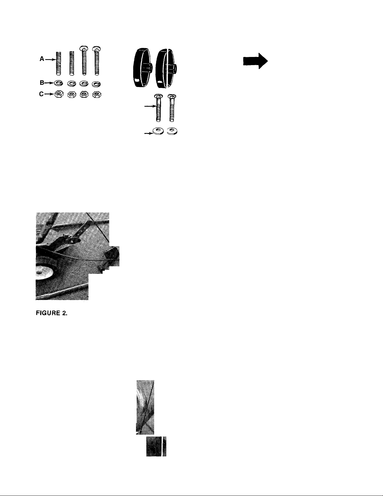
FIGURE 1.
Right Hand
Upper Handle
ASSEMBLY
NOTE
This unit is shipped WITHOUT GAS
OLINE or OIL. After assembly, see
separate engine manual for proper
fuel and engine oil recommenda
tions.
NOTE
Reference to left or right side of the
tiller is determined from behind the
unit in the operating position.
' Contents of Hardware Pack (See Figure 1):
A (4) Carriage Boits 5/16-18 x IVa" Long
B (4) Lock Washers 5/16" I.D.
C (4) Hex Nuts 5/16-18 Thread
D (1) Cable Tie
E (2) Curved Head Bolts
F (2) Belleville Washers 5/16" I.D.
G (2) Hand Knobs
Loose Parts in Carton:
(1) Upper Handle—R.H.
(1) Upper Handle—L.H.
(1) Handle Panel
Tools Required
(2) Vz" open end or box wrenches
^ Left Hand
/
Belleville
Washer (F)
High
Positi
Hand
Knob (G)
Upper Handle
Curved Mead
Bolt (E in
Low Pos tion
1. Remove the tiller from the carton. Make cer
tain all parts and literature have been removed
before the carton is discarded.
2. Extend the control cables and place on the
------
floor. Be careful not to bend or kink the
cables.
There are two height positions for the upper
3.
handles. Place left hand upper handle (with
clutch grip and cable support bracket already
assembled) in position on lower handle,
selecting hole for either high or low position.
Secure with curved head bolt (E), belleville
washer (F) (cupped side against the handle)
■ and hand knob (G). See figure 3. Do not
tighten at this time. Assemble right hand up
per handle in the same manner.
FIGURE 3.
Page 5
Carriage
Boit (A)
4. Place the handle panel in position on the up
per handies. Secure in position with four car
riage bolts (A), lock washers (B) and hex nuts
— (C). See figure 4.
Handle
Panel
\
FIGURE 4.
Lock Bracket
Washer (B)
Hex Nut (C)
Cable Support
NOTE
Carriage bolt on the upper left hand
side of handle panel also secures
the cable support bracket.
5. Tighten securely all nuts and bolts used in
handle assembly.
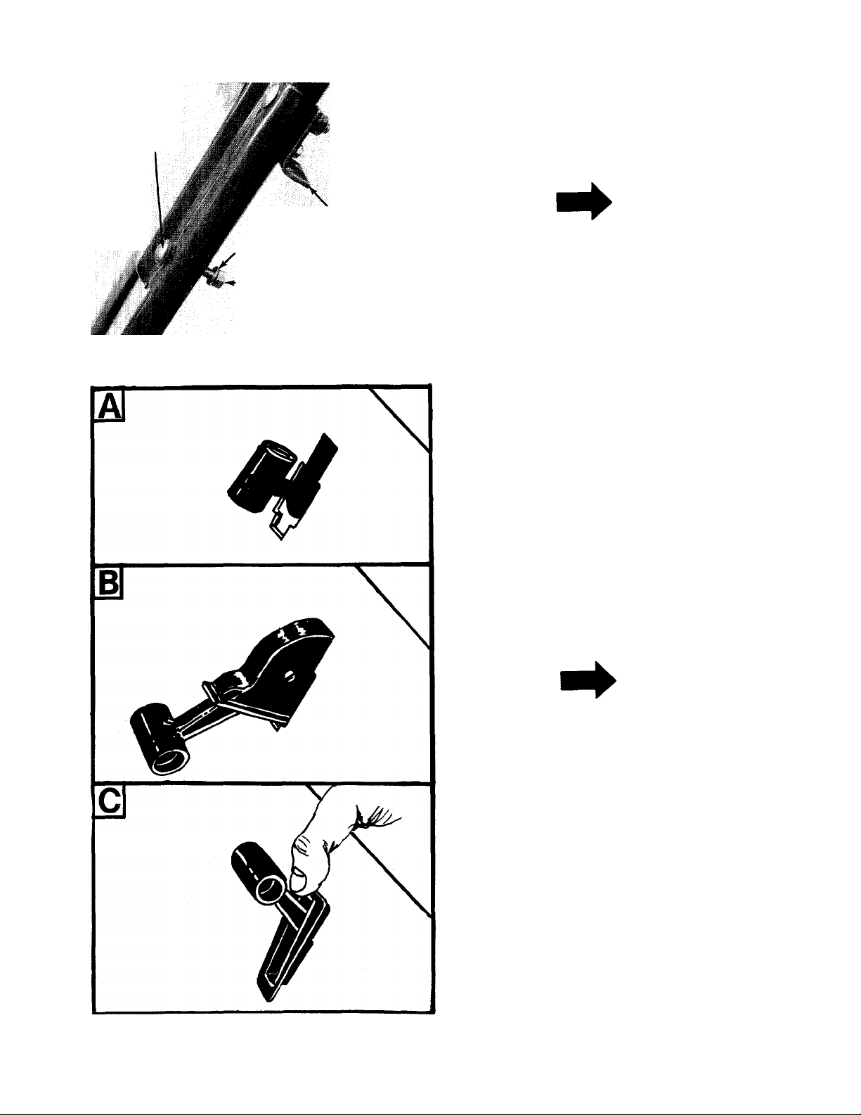
6. Assemble the throttle control to the handle
panel as follows.
A. Hold the throttle control assembly
beneath the handle panel. Turn the control
sideways and insert the lever up through
the wide portion of the slot on the handle
■ panel. See figure 5A.
B. After the end of the iever is through the
slot, turn and then tip the control forward
■as shown in figure 5B to slide it through
the slot.
FIGURE 5.
NOTE
The lever must be all the way to the
back of the control housing as
shown in figure 5B.
C. Push the control back into the slot in the
handle panel and press in place. Be certain
the control is locked securely into the slot.
-See figure 5C.
Page 6

• .iliihr ^ Ï-» ci^4 :
FIGURE 6.
Lock
Washer
Slot in
Cable Support
Bracket
7.
Remove one hex nut and lock washer from
end of clutch cable. Slip the wire up through
slot on cable support bracket. Start hex nut
and lock washer back on end of clutch cable.
See figure 6.
8.--Hook the “Z” end of clutch cable wire into
-----bottom hole of clutch grip. See figure 7.
9. Hold the clutch grip so that the grip is down
against the handle. Adjust the clutch control
cable so that the slack is taken out of the con
trol wire. Tighten the two hex nuts at the cable
support bracket. Control wire should now be
straight.
A
Do not overtighten control wire. Too
much tension may cause it to break.
10. To check the adjustment, disconnect the
spark plug wire from spark plug to prevent ac
cidental starting. Secure end of spark plug
wire in the “V” slot on the engine. See figure
■8. With the clutch grip released (neutral posi
tion), pull starter cord several timbs. The tines
should not turn. If they do, adjust the hex nuts
at the clutch cable bracket. Check again for
correct adjustment.
CAUTION
FIGURE 8.
Page 7

FIGURE 9.
11. Secure the clutch cable to the upper handle
with cable tie (D) provided in hardware pack.
------
See figure 9. Cut off excess end.
OPERATION
BEFORE STARTING ENGINE
1. Check clutch adjustment before starting tiller. Refer to step number 9 of Assembly Instruc
tions.
2. Fill crankcase with VA pints of oil or to top of
filler neck. Be sure that the engine is level.
See figure 10.
Use SAE No. 30 MS, SC, SD or SE oil. If not
available, use SAE 10W-30.
Oil Fill
TO START ENGINE
^ WARNING ^
BE SURE NO ONE IS STANDING IN
FRONT OF THE TILLER WHILE THE
ENGINE IS RUNNING OR BEING
STARTED.
1. Attach spark plug wire to spark plug.
2. Be certain the clutch grip is in the neutral
(released) position. See figure 11.
Clutch'
Grip
Throttle
Control
1
i
FIGURE 10.
3. Fill fuel tank using a good grade of fresh,
clean, regular gasoline. Do not use gasoline
that has been sitting for a long period of time.
FIGURE 11.
3. Pull choke knob out to choke engine. See
figure 12.
4. Move the throttle control lever forward to
FAST POSITION. See figure 11.
5. Standing at side of the tiller, grasp the starter
handle and pull out rapidly. Return it slowly to
the engine. Repeat if necessary.
Page 8

6. After engine starts, push choke knob gradual
ly in to “OFF” position.
NOTE
Warm engine should not need chok
ing.
iiii Ui:' ■ '>
■ r.
Choke Knob
kPIIH
■SI
Pull Out To Choke
(SJipwn in Choke Posi' ion)
FIGURE 12.
TO STOP ENGINE
1. Move throttle control lever to “STOP’ posi
tion.
2. Disconnect spark plug wire from spark filug to
prevent accidental starting while equiament
is unattended.
CONTROLLING SPEED AND TILLING DEPTH
The tiller has eight 10-inch diameter, spring steel
tines. Tine speed is 160 RPM The normal tilling
depth is 41/2 inches deep. It may be chanjied by
adjusting the depth bar and pressure exer:ed on
the handles. The tilling width may also be /aried.
See adjustment section.
Throttle Control
The throttle control lever is located on th 3 right
hand side of handle.
NOTE
the throttle control to slow when transporting the
tiller. When the tiller is being moved to or-from the
garden, the depth bar should be raised up until it
clears the ground.
The machine may be moved under its own power,
without damaging grass areas as long as it is
allowed to move freely. If the operator holds back,
it will start to dig.
Depth Bar
The depth bar acts as a brake for the tiller and con
trols the depth and speed at which the machine
will operate. You may till deeper by moving the
depth bar all the way down. See adjustment sec
tion.
Handle Pressure
Further control of tilling depth and travel speed
can be obtained by variation of pressure on the
handle. An upward pressure on the handle will
reduce the working depth and increase the for
ward speed. A downward pressure on the handle
will increase the working depth and reduce the
forward speed. The type of soil and working condi
tions will determine the actual setting of the
depth bar and the handle pressure required.
ADJUSTMENTS
A
Remove the spark plug wire from
spark plug and ground against the
engine block (secure in “V” slot)
before making any adjustments or
performing maintenance. See fig
ure 8.
HANDLE POSITION
The upper handle can be adjusted to two different
heights. The operator of the tiller can easily adjust
the handle position by unscrewing the two knobs,
removing the two bolts and reassembling in
another position. No tools are necessary to make
this adjustment. See figure 13.
CAUTION
Right hand side is determined frorr
the operator’s position standing be
hind the tiller.
The throttle control lever adjusts the engine
speed. It also gives finger tip control of tie car
buretor and magneto stop switch. With the throt
tle control knob pushed completely forwerd, the
carburetor is in FAST position. Pulling the i hrottle
control back slightly adjusts the engine sfieed to
START. Pulling the throttle back further rsduces
the engine speed to SLOW. When the thnttle is
pulled completely back, the magneto stop switch
grounds out the spark and stops the engine. Move
Page 9

DEPTH BAR ADJUSTMENT
The working depth of the tiller is determined by
the position of the depth bar. Remove the clevis
pin and internal cotter pin to raise or lower depth
bar. See figure 14.
Depth Bar
Six Hole
Adjustment.
Clevis Pin a
Internal Cl
FIGURE 14.
TILLING WIDTH
There are three tilling widths available.
Remove the spark plug wire from spark plug and
ground before making any adjustments to tine
width.
1. Standard tilling width is 18 inches. See figure
15.
3/8" Wrench
Self-Tapping
Screws
FIGURE 16.
FIGURE 15.
2. A narrower width (14 inches) can be obtained
by removing both outer tines. Use a 3/8"
wrench to remove the two self-tapping screws
on the outside of the tines. See figure 16.
Replace the first tine removed as shown in
figure 17.
FIGURE 17.
3. The minimum tiller width that can be obtained
is 10 inches. Remove the outer tines by remov
ing the two self-tapping screws on the outside
of the tines. See figure 18.
Self-Tapping
Screws
FIGURE 18.
Self-
Tapping
Screws
Page 10

CLUTCH ADJUSTMENT
Refer to step numbers 8 and 9 of Assemlily In
structions for clutch adjustment informatici.
CARBURETOR ADJUSTMENT
^ WARNING \
If any adjustments are made to the
engine while the engine is running
(e.g. carburetor), disengage all
clutches and tines. Keep clear of
all moving parts. Be careful of
heated surfaces and muffler.
Never make unnecessary adjustments. Ths fac
tory recommended settings are correct for most
applications.
If adjustments are needed, refer to the engine
manual packed with the tiller.
LUBRICATION
Chain Case
The chain case is pre-lubricated and sealed at the
factory. It requires no checking unless the chain
case is disassembled. To fill with grease, lay the
right half of the chain case on its side, ^^dd 10
ounces of Plastilube #0 grease and assemt le the
left half to the right half. The grease can ae ob
tained at your nearest authorized dealer Us ed on
the back of this manual. Order part no. 737 0133.
MAINTENANCE
Change the oil in the crankcase after the first two
hours of operation of your new engine and after
each 25 hours of use thereafter. This will ensure
proper lubrication of internal parts to prevent ex
cessive wear.
To change the oil, remove drain plug and tip the
tiller forward while engine is warm. See figure 19.
Replace drain plug. Remove oil filler cap, taking
care to remove dirt around filler plug. Refill with
new oil of proper grade. Replace filler cap.
AIR CLEANER
Service the air cleaner every 25 hours of operation.
The air cleaner prevents damaging dirt, dust, etc.
from entering the carburetor and being forced into
the engine. It is important to engine life and per
formance.
To service air cleaner, refer to the engine manual
packed with the tiller.
Never run your engine without air cleaner com
pletely assembled.
SPARK PLUG
The spark plug should be cleaned and the gap
reset at least once a season or when oil is
changed. Spark plug replacement is recom
mended at the start of each season; check engine
manual for correct plug type and gap specifica
tion.
CLEAN ENGINE
Wipe off all spilled fuel and oil. Keep the imgine
clean of foreign matter and be sure the cooling
fins on the cylinder are kept clean to permit proper
air circulation. This is an air cooled engine and
free flow of air is essential to proper engine per
formance and life.
ENGINE OIL
Check oil level before each use. Be sure oil evel is
maintained full to point of overflowing. See figure
FIGURE 19.
BELT REPLACEMENT
1. Remove belt cover assembly by removing one
hex nut and flat washer, one seif-tapping
screw, one hex screw, flat washer and hex
nut. See figure 20.
2. Lift the belt cover assembly off the tiller. Be
careful not to bend or kink the clutch cable.
See figure 20.
3. Remove the belt and position the new belt on
engine pulley and chain case pulley.
NOTE
Upon reassembly of belt cover,
place the belt over top of the idler
pulley and between engine pulley
and weld pin on belt cover assembly.
See figure 20.
4. Fasten belt cover assembly in position.
Secure with the hardware removed in step 1.
10
Page 11

FIGURE 20.
OFF SEASON STORAGE
If the tiller is not to be used for a while, the follow
ing procedure should be followed. The tines,
depth bar, chain case and wheels should be
cleaned of all dirt. It is very important that the unit
be stored in a level position to prevent engine oil
from draining into the cylinder head cavity.
Engines on tillers to be stored between seasons
should be completely drained of fuel to prevent
gum deposits forming on essential carburetor
parts and fuel tank.
1. All fuel should be removed from fuel tank. Run
the engine until it stops from lack of fuel. The
small amount of fuel that remains in the sump
of the tank should then be removed by absorb
ing it with a clean dry cloth.
2. Clean dirt and chaff from cylinder, cylinder
head fins and blower housing.
3. Remove spark plug, pour 2 or 3 tablespoons of
SAE-30 oil into cylinder and pull crank cord
out slowly to distribute oil. Replace spark
plug.
CAUTION
A
When storing any type of power
equipment in an unventilated or
metal storage shed, care should be
taken to rust proof the equipment.
Using a light oil or silicone, coat the
equipment, especially any chains,
springs, bearings or cables.
11
Page 12

TROUBLIE SHOOTING CHART
SYMPTOM
Engine fails to start
Hard starting or loss of
power
Engine overheats
Tine control does not
engage
POSSIltLE CAUSE(S)
1. Check uel tank for gas.
2. Spark plug lead wire
discc nnected.
3. Faulty ;ipark piug.
1. Spark p lug wire loose.
2. Dirty air cleaner.
1. Carbunstor not adjusted
prop jrly.
2. Air flov/ restricted.
3. Engine oil level low.
Belt worn and/or
stretched
SOLUTION
1. Fill tank if empty.
2. Connect lead wire.
3. Spark should jump gap between
control electrode and side elec
trode. If spark does not jump,
replace the spark plug.
1. Connect and tighten spark plug
wire.
2. Clean air cleaner as described in
engine manual.
1. Adjust carburetor. See engine
manuai.
2. Remove blower housing and clean
as described in the engine
manual.
3. Fill crankcase with the proper oil.
Make control cable adjustment (see
Assembly Instructions) or replace
belt.
NOTE; For repairs beyond the minor adjustments listed above, please contact your local service dealer.
12
Page 13

Chain Case Assembly 04924
Model 031
Lubricate with 10 oz. of Piastiiube #0 Grease. Order Part No.
737-0133.
PARTS LIST FOR CHAIN CAS
REF.
PART
NO.
1
04926 —497 Chain Case Ass’y.—R H.
2
04756 Input Shaft Ass’y.
3 04757
4
750-0351
5 741-0155
NO.
COLOR
CODE
DESCRIPTION
Hub and Sprocket Ass’y.
Bearing Inner Race
Ball Bearing
6 15863 —497 Chain Case Ass’y.—L.H. N
7 756-0287 Pulley—Chain Case
8
710-0331
10
721-0157
11
710-0195
12
721-0156
13
741-0227 Flange Brg. .879 l.D.
14
736-0265
51/2 X 1/2 tt
Hex Bolt 3/8-24 x 2.50" Lg.*
Sealft
Hex Bolt 1/4-28 X .625" Lg.*
Gasket
FI-Wash. .88 l.D. x
1.50 O.D. X .030
14 04920 Tine Shaft Ass’y.
16
750-0354 Spacer 7/8" l.D. x 2.0" O.D.
X .68" Lg.
17
736-0329
18
712-0138
19 712-0116
20
736-0169 L-Wash. 3/8" Scr.*
L-Wash. 1/4" Scr.*
Hex Nut 1/4-28 Thd.*
Hex Nut 3/8-24 Thd.*
tfNot part of chain case assembly.
NEW
PART
E ASSEMBLY 0^
REF.
NO.
PART 1 COLOR
NO. 1 CODE
736-0219 Bell-Wash. .406 l.D. x
21
1924
DESCRIPTION
1.130 O.D.
22
713-0215
Chain #420—.50" Pitch x
38 Links
23
713-0216
Chain #35—.375" Pitch x
50 Links
748-0154 Bearing .62" l.D. x .813
24
O.D. X 1.31
25 05034
726-0164 Expansion Plug 13/16" Dia.
26
27 741-0228
731-0486
28
710-0599
29
750-0471
30
Bearing Housing
Bearing
Dust Captt
Hex Wash. Hd. Self-Tap Scr.
1/4-20 X .50" Lg.
Spacer .630 l.D. x .77 O.D. x
.38" Lg.
31
715-0114
Spring Pin Spiral 1/4" Dia. x
11/2 " Lg.
750-0550 Spacer .647 x 1.25"
32
33
710-0653
Hex Wash. Hd. Self-Tap Scr.
1/4-20 X .38" Lg.
NEW
PART
13
Page 14

Model 031
IF YOU WRITE TO US ABOUT THIS ARTICIE
OR IF YOU ORDER REPLACEMENT PARTS AL
WAYS MENTION THIS MODEL & SERIAL NO
MODEL
Page 15

Model 031
REF.
NO.
10
11
12 712-0256
13
14
15 746-0509
16
17 749-0630
18
19
20 784-0018
22 736-0290
23 710-0405
24 711-0653
25
26 738-0126
27 04764 —463
28
29 714-0145
30 04918
31
32 04923
720-0204
1
PART
NO.
COLOR
CODE
2 831-0692
04947
3
4 738-0561
784-0007
5
738-0572
6
710-0262
7
8
15093
9
710-0599
712-0267
736-0119
736-0119
725-0157 Cable Tie
749-0631
746-0419
710-0289
734-0840
711-0702
710-0599
PARTS LIST FOR MODEL 031 TILLER
NEW
DESCRIPTION
Grip
Throttle Control Box Ass’yHandle Panel
REF.
PART
NO.
33 04922 Tine Blade—R.H.
N
34 04921 Tine Ass’y. Comp.
35 04924
PART
NO.
COLOR
CODE
—463
DESCRIPTION
Chain Case Ass’y. Comp.
Shoulder Nut 36 712-0267 Hex Nut 5/16-18 Thd.*
Clutch Grip Ass’y-
37
736-0119
L-Wash. 5/16" I.D.*
N
Shoulder Bolt 3/8 x 1.160" 38 736-0217 L-Wash. 3/8" I.D. (Heavy
Lg-
N
Duty)
Carriage Bolt 5/16-18 x 1.5" 39 712-0375 Hex Cent. L-Nut 3/8-16 Thd.
Lg-*
Cable Support Bracket
Hex Wash. Hd. Self-Tap Scr. 41 04762
1/4-20 X .50" Lg. 42 712-0107 Hex Cent. L-Nut V4-20 Thd.
Hex Nut 5/16-18 Thd.* 43
40 710-0600
N
—463
714-0104
Hex Wash. Hd. Self-Tap Scr.
5/16-18 X .50" Lg.
Support Brkt. Ass’y.
Internal Cotter Pin
L-Wash. 5/16" I.D.* 44 09966 Hand Knob
Hex Jam Nut 5/16-24 Thd. 46 784-0016
L-Wash. 5/16" I.D.*
47
754-0216 Belt 3/8" X 29" Lg.
48 756-0287
Clutch Control Cable
Upper Handle—L.H.
Upper Handle—R.H.
N
N
N
Throttle Control Wire 26" 53
Lg-
Hex Bolt 55
Belt Cover Ass’y.
N
756-0199 Fl-ldler2"
49
736-0119 L-Wash. 5/16" I.D.*
50
51 712-0116 Hex Nut 3/8-24 Thd.*
04765 —312 Tine Shield
54
736-0169 L-Wash. 3/8" I.D.*
710-0442 Hex Bolt 5/16-18 X 1.50" Lg.
56 756-0286 Engine Pulley 3/8 V x .75
FI-Wash. .52" I.D. x 1.00"
O.D.
57 736-0258 FI-Wash. .385" I.D. x 1.00"
Curved Hd. Bolt 5/16-18 x
710-0152
1.75" Lg.
Clevis Pin
Wheel Ass’y. Comp. 7.0" x
1.5
Shoulder Bolt
Depth Bar
58
712-0267
59
60 736-0289 Shid. Spacer .50" Dia. x .133
61 784-0033
63 731-0511
64 736-0142 FI-Wash. .281" I.D. x .500"
Clevis Pin .31" Dia. x 1.50"
712-0107
Lg.
Hairpin Cotter
Tine Adapter Ass’y.
Hex Wash. Hd. Self-Tap Scr.
1/4-20 X .50" Lg.
65
67
—
68 736-0219 Bell-Wash.
714-0122
69
70 736-0242 Bell-Wash.
Idler Arm Ass’y.
Chain Case Pulley 5V2 x Vz"
I.D. X 2" O.D.
O.D.
Hex Bolt 3/8-24 x 1.00" Lg.*
Hex Nut 5/16-18 Thd.*
Throttle Control Bracket N
Trim Strip—4"
O.D.
Hex Cent. L-Nut V4-20 Thd.
Engine
Square Key 3/16 x ¥4" Lg.
Tine Blade—L.H.
NEW
PART
*For faster service obtain standard nuts, bolts and washers locaily. If these Items cannot be obtained
iocaily, order by part number and size as shown on parts list.
(463—Top Fiite Red) When ordering parts if color or finish is important, use the appropriate color code
This instruction manuai covers various models
and all specifications shown do not neces
sarily apply to your model. Specifications sub
ject to change without notice or obligation.
shown at left. (e.g. Top Fiite Red Finish—04762 (463).)
NOTE
15
NOTE: The engine is not under warranty by
the tiller manufacturer... If repairs or service
is needed on the engine, please contact your
nearest authorized engine /t—7
service outlet. Check the Find It Fast
“Yellow Pages” of your In The
telephone book under Yellow Pages
“Engines—Gasoline.”
----------------------
Page 16

PARTS INFORMATION
POWER EQUIPMENT PARTS AND SERVICE
Parts and service are available through the authorized service
firms listed below. All orders should specify the model numt er of
your unit, part numbers, description of parts and the quant ty of
each part required.
NOTE: If any parts are found to be missing or defective upon assembly of this unit, write to advise the factory so
that immediate replacement can be mad 3.
ALABAMA
Auto Electric & Carburetor Co.
ARKANSAS
Sutton's Lawn Mower Shop .. .
CALIFORNIA PORTERVILLE
Billious
COLORADO DENVER
FLORIDA JACKSONVILLE
GEORGIA EAST POINT
ILLINOIS LYONS
INDIANA ELKHART
IOWA DUBUQUE
LOUISIANA new ORLEANS
MARYLAND TAKOMA PARK
MASSACHUSETTS SPRINGFIELD
MICHIGAN LANSING
MINNESOTA HOPKINS
MISSISSIPPI BILOXI
MISSOURI KANSAS CITY
NEW JERSEY BELLMAWR
NEW MEXICO ALBUQUERQUE
NEW YORK CARTHAGE
.............................................
Spitzer Industrial Products Co. . . . 6601 N.
Radco Distributors
Small Eng. Dist
East Point Cycle & Key
Keen Edge Co
Parts & Sales Inc
Power Lawn & Garden Equip
Suhren Engine Co
Center Supply Co
Morton B. Collins Co
Lorenz Service Co......................... 2500 S. Pennsylvania .
Power Equipment Dist.................. 340 Hubbard
Hance Distributing Inc.................. 420 Excelsior Ave. W.
Biloxi Sales & Service, Inc
Automotive Equip. Service ..............3117 Holmes St
Ross-Frazier Supply Co
Henzier, Inc....................................2015 Lemay Ferry Rd.
Lawnmower Parts Inc...................717 Creek Rd
Spitzer Eng. & Parts
Gamble Dist., Inc
..........................
................................
...................
..................................
.............................
...........................
..........................
....................
...............
........................
...........................
BIRMINGHAM
. . 2625 4th Ave.S
NORTH LITTLE ROCK
. . 5301 Roundtop Drive
Box 368, Rt. 4
75 North D Street............
Washington St
4909 Victor St.
Box 5459
OPA LOCKA
2351 N.W. 147th St. . . .
2834 Church St
8615 Ogden Ave
2101 Industrial Pkwy...
.........
2551 J.F. Kennedy . . . .
8330 Earhart Blvd. . . .
6867 New Hampshire
Ave
...............................
300 Birnie Ave
MOUNT CLEMENS
.............
506 Caillavet St
ST. JOSEPH
8th and Monterey ....
ST. LOUIS
1023 Third Ave. N.W. .
West End Ave
..............
...............
..............
......................
..............
.............
................
...............
............
...........
...............
...............
'15233 Smith Hardware Go...........................515 N. George St
■2117 OHIO CARROLL
113257 CLEVELAND
¡10229 National Central
¡2207 Box 929
13054 Victory Motors, Inc............................ 605 S. Cherokee...........74401
¡0344 Kenton Supply Co.............................8216 N. Denver Ave. . . .97217
10534 EECOInc............................................. 4021 N. 6th St
¡6516 Thompson Rubber Co
52001 BluemontCo.......................................11125 Frankstown Rd. .15235
70118 Frank Roberts & Sons
20912 TENNESSEE KNOXVILLE
01107 MEMPHIS
48910 TEXAS DALLAS
48043 FORT WORTH
.
55343 HOUSTON
39533 SAN ANTONIO
64109 P.O. Box 17867
64503 A-1 Engine & Mower Co
63125 RBI Corp..............................................101 Cedar Ridge Dr. . . . 23005
08030 Bailey’s Inc
87103 Automotive Supply Co
13619 CHILTON
BRIGGS AND STRATTON, TECUMSEH AND PEERLESS PARTS
AND SERVICE
Briggs & Stratton, Tecumseh and Peerless parts and service
should be handled by your nearest authorized engine service firm.
Check the yellow pages of your telephone directory under the
listing Engines—Gasoline, Briggs & Stratton or Tecumseh
Lauson.
NORTH CAROLINA GOLDSBORO
Dixie Sales Company
Stebe’s Mid-State Mower Supply . Box 366, 71 High St.. . . 43112
Bleckrie, Inc
Burton Supply Co
OKLAHOMA MUSKOGEE
OREGON PORTLAND
PENNSYLVANIA HARRISBURG
Scranton Auto Ignition Co
Master Repair Service .................... 2000 Western Ave........37921
American Sales & Service, Inc. . . . 3035-43 Bellbrook . . . .38116
Marr Brothers, Inc
Woodson Sales Corp
Bullard Supply Co
Engine House Inc
UTAH SALT LAKE CITY
VIRGINIA ASHLAND
WASHINGTON SEATTLE
WISCONSIN APPLETON
Horst Dist.......................................... 444 N. Madison
............,........................
....................................
......................
................................
............................
......................
.....................
............................
......................
...........................
............................
....................
......................
GREENSBORO
335 N. Green
7900 Lorain Ave
WADSWORTH
687 Seville Rd
YOUNGSTOWN
1301 Logan Ave.
PHILADELPHIA
5222-24 N. Fifth St
PITTSBURGH
PUNXSUTAWNEY
R.D. 2
SCRANTON
..............
1133-35 Wyoming Ave. 18509
1702 N. Sylvania
2409 Commerce St. ... 77003
8610 Botts Lane
. 1414 14th Ave
..............................
423 E, Jefferson
439 E. 900 So
123 S. Linwood Ave.
P.O. Box 798
...........
.................
............
..............
.........................
...............
........
..........
..........
..........
...............
................
................
............
27530
27402
44102
44281
44501
17110
19120
15767
75203
76111
78217
84111
98122
54911
53014
WARRANTY
The purpose of warranty is to protect the customer from
time of manufacture. It does not provide for the unlimitg
sibility of the customer. The manufacturer cannot assur
the manufacturer’s fault, it’s the manufacturer’s respons
CLAIMS AGAINST THE MANUFACTURER’S WARRANTS
INCLUDES:
1. Replacement of Missing Parts on new equipment.
2. Replacement ot Defective Parts within the warranty (
3. Repair ot Defects within the warranty period.
MTD PRODUCTS INC P.O. BOX 36900 CLEVELAND, OHIO 44136
PARTS AND SERVICE POLiCY (0783)
defects in workmanship and materials, defects which are NOT detected at the
d and unrestricted replacement of parts. Use and maintenance are the responle responsibility for conditions over which it has no control. Simply put, if it’s
bility; if it’s the customer’s fault, it’s the customers’s responsibility.
All claims MUST be substantiated with the following
information:
1. Model Number of unit involved.
leriod. 2. Date unit was purchased or first put into service.
3. Date of failure.
4. Nature of failure.
 Loading...