

Page 1

ЮФ
Model Nos.
213-380
ROTARY TILLER
For one year from date of purchase, MTD Products Inc.
will replace for the original purchaser, free of charge,
F.O.B. factory or authorized service firm, any part or
parts found to be defective in material or workman
ship. All transportation charges on parts submitted
for replacement under this warranty must be paid by
the purchaser. This warranty does not include replace
ment of parts which become inoperative through mis
use, excessive use, accident, neglect, improper main
tenance or alterations by unauthorized persons. This
warranty does not include the engine, motor, battery,
battery charger or any component parts thereof. For
service on these units refer to the applicable manu
facturer's warranty.
The above warranty will apply only to the original
owner and will be effective only if the warranty card
has been properly processed. It will not apply where
the unit has been used commercially.
Warranty service is available through your local au
thorized service dealer or distributor. UNDER NO CIR
CUMSTANCES WILL THE RETURN OF A COMPLETE
UNIT BE ACCEPTED BY THE FACTORY UNLESS PRIOR
WRITTEN PERMISSION HAS BEEN EXTENDED.
213-385 «HI?
1. Your tiller is a precision piece of power equipment.
Exercise extreme caution at all times.
2. Do not attempt to start engine with the clutch con
trol in the engaged or FORWARD position.
3. Stand clear of tines when starting engine. Never
stand in front of, or work on tines while the en
gine is running.
4. NEVER place hands or feet in the vicinity of the
tines while the engine is running.
5. Always stop engine when tiller is not in actual use.
6. Always disconnect spark plug wire during repairs
or refueling operations.
7. Do not fill gas tank while engine is running. Do not
spill gasoline on hot engine.
Your rotary tiller is a precision built machine designed
to take the work out of gardening and other related
chores. It can be used for seed bed preparation, tilling,
cultivating, furrowing, composting and mulching. Like
any other piece of power equipment, it requires a cer
tain amount of care and maintenance. In return for
this, it will give a maximum of service and efficiency.
Read these instructions carefully before assembling or
operating your tiller. Through proper care and opera
tion, you will obtain long, efficient service and trouble
free operation.
MTD PRODUCTS INC
5389 WEST 130th STREET • P. 0. BOX 2741 CLEVELAND OHIO 44111
FORM NO. 770-4121
Page 2
ASSEMBLY
HANDLE ASSEMBLY
Your rotary tiller is shipped complete in a single car
ton. The wheels, handle, controls and depth bar are
to be assembled. This is done in the manner described
below.
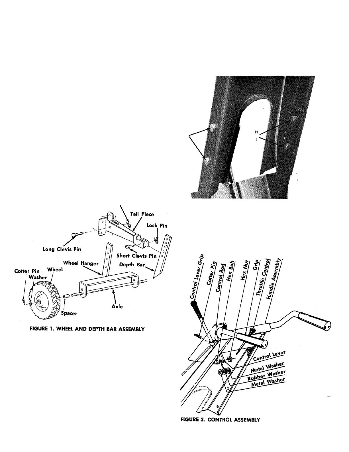
WHEELS
Assemble the axle to the wheel hanger. Place the
spacer over the axle and assemble the wheel, with a
washer on both sides of the wheel, to the axle. See
figure 1. Secure each wheel with a cotter pin.
Place the wheel hanger inside the tailpiece and secure
with the long clevis pin and lock pin. See figure 1.
DEPTH BAR
Assemble the depth bar to the tail piece using the
short clevis pin and lock pin. See figure 1.
Lock Pin
Assemble the handle to the handle brackets with four
cap screws, lockwashers and hex nuts as shown in
figure 2.
FIGURE 2. HANDLE ASSEMBLY
CONTROL LEVER
Place clutch control lever through handle panel. Se
cure in place with hex bolt, flat washers, rubber wash
er and hex nut. See figure 3.
Page 3
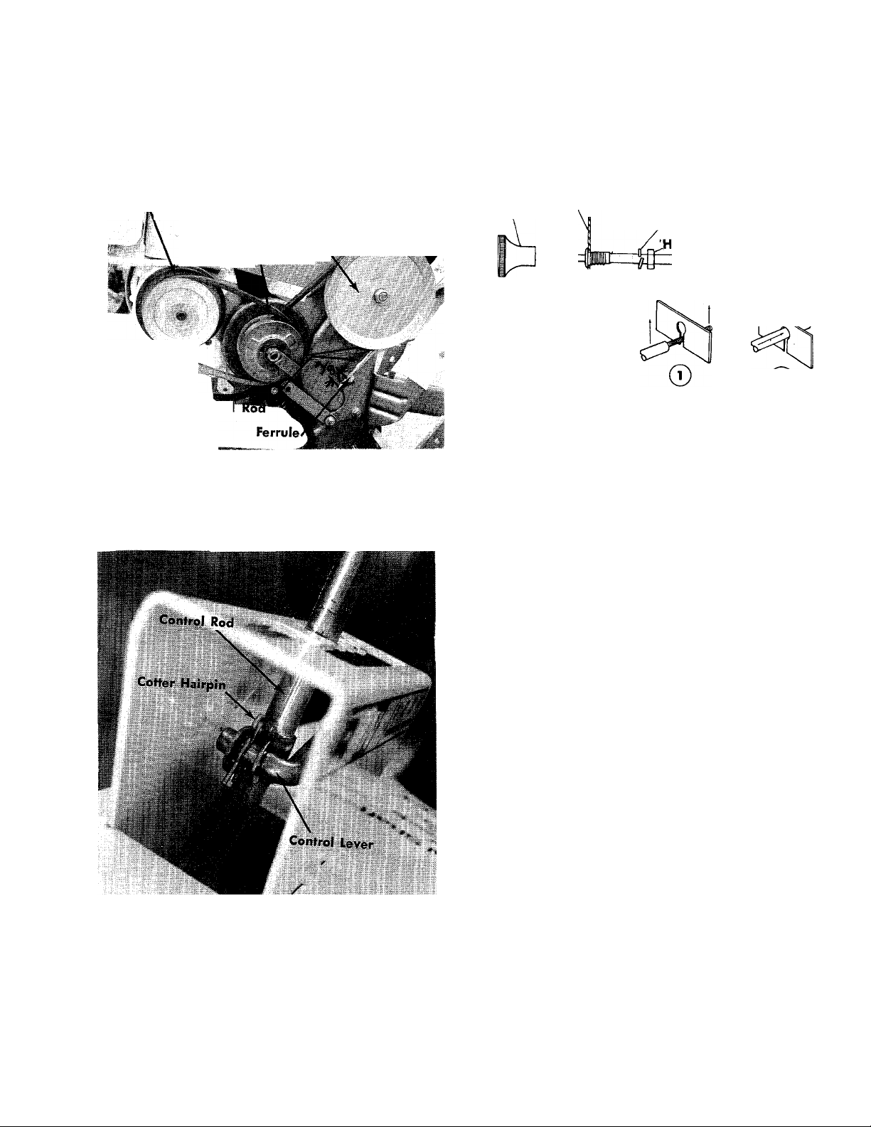
CONTROL ROD
Screw the control rod into the ferrule until it extends
through the ferrule % of an inch. See figure 4.
THROTTLE-Assemble as shown in figure 6.
Engiiis|T»uHey
«a. '
VanSBle Speed Pulley
Control
FIGURE 4. FERRULE ADJUSTMENT
Place the bent end into the control handle as shown
in figure 5 and fasten with a cotter hairpin.
j-J"- ■ Chain Case'^Ej^HI
Pulley
Knob
Handle Panel
Spring Lockwasher
ex Nut
Conduit
©
FIGURE 6. THROTTLE CONTROL
CHECK LIST BEFORE OPERATION
1. Check tiller tines for proper installation. With throt
tle control lever set on STOP position and the con
trol lever set in No. 1 position, slowly crank engine
to determine direction of tine rotation. Be sure all
tines are mounted so the sharpened edges enter
the soil first.
FIGURE 5. CONTROL ROD
CAUTION
With the spark plug wire disconnected
and grounded, place the control lever in
NEUTRAL and pull the recoil starter sev
eral times. THE TINES SHOULD NOT
TURN. If they do, screw the control rod
into the ferrule several more turns as
shown in figure 4.
2. Check all nuts and bolts for proper tightness. This
is especially important during the initial operation
period. Make the same check periodically there
after.
3. Check throttle control for proper setting. Move
throttle control knob to STOP position. Move lever,
to which control wire is fastened at engine, to
CLOSE position and retighten screw to secure throt
tle control wire assembly.
4. Check fuel tank. Clean, fresh, regular gasoline
should be used at all times.
5. Check engine crankcase for proper oil level. The
engine is shipped without oil in the crankcase. Be
sure crankcase is FULL.
STARTING YOUR TILLER
1. Be sure clutch control handle is in NEUTRAL posi
tion.
2. Move throttle control lever to STOP position.
3. Move choke lever, located at the engine, to CHOKE
position. Refer to your engine manual.
Page 4
4. After cranking the engine several times, or as the
engine fires, move the throttle control lever to RUN
position.
5. Use CHOKE as needed to keep engine operating
during warm-up period.
6. Set the throttle control in the FAST position.
7. Move the control lever into the number one posi
tion and the tines will begin rotating. Number four
position will give the maximum tine speed. Tilling
the ground for the first time should be done in the
number one or two position. To pulverize the soil
after it has been tilled, move the control lever to the
number three or four position.
NOTE
The engine must be running to move
the control lever into the faster speeds.
8. To stop engine, move throttle control lever to STOP
position. Keep throttle control lever in STOP posi
tion at all times when tiller is not in use.
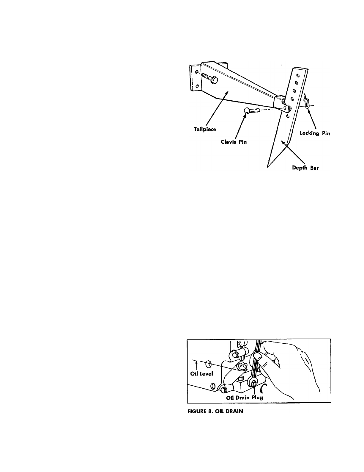
FIGURE 7. DEPTH BAR
11. The wheel height can be adjusted by removing
the long clevis pin for the wheel hanger and rais
ing or lowering the setting. See figure 1.
NOTE
A brief break-in period is essential to
insure maximum engine life. This con
sists of running the engine at half speed
for a period of time required to use one
tank of gasoline. This is necessary on
the initial run only. It is also recom
mended that the oil be changed after
five (5) hours of operation. This allows
for the removal of impurities which
may have accumulated during the breakin period. Subsequent oil changes
should be made as stated in the engine
manual. Always check oil before using
your tiller. Be sure crankcase is full.
9. To reverse the tine rotation to back up or release
an object jamming the tines, pull the control lever
into the REVERSE position.
NOTE
The control lever must be held in the
REVERSE position. When you release the
lever it will go into the NEUTRAL posi
tion.
NOTE
Pick a height that places the handles in
a comfortable position for the operator.
The higher the setting, the deeper you
till.
MAINTENANCE AND lUBRICATION
ENGINE—Service engine in accordance with the en
gine manufacturer's owner's guide. Note: To drain oil
remove oil drain plug and tip tiller forward. Drain oil
while the engine is warm. See engine manual for fil
ling instructions.
1,0. The depth bar acts as a brake for the tiller and con
trols the tilling depth and ground speed. By low
ering the setting of the depth bar, the forward
speed of the tiller is reduced and the tilling depth
of the tines is increased. Raising the settings of
the depth bar increases the forward speed and
reduces the working depth. See figure 7.
THROTTLE—Periodically lubricate throttle control lever
and throttle control wire assembly with a few drops
of light oil (SAE 10 or 20) for ease of operation.
Page 5

AIR CLEANER
CHAIN ADJUSTMENT
1., Remove wing nut and cover.
2. Lift off foam element from support base.
3. Remove metal support tube assembly (screen and
two metal end caps) from foam element by com
pressing foam element. See figure 9.
4. Wash the element in a solvent such as kerosene.
Squeeze dry and blot to remove all kerosene or sol
vent. Saturate element with engine oil. Squeeze
element to distribute and remove excess oil.
5. Insert metal support tube assembly into element so
that end cap without projection enters first. Make
sure metal caps are seated on screen.
IMPORTANT: When support tube is in place, pull rub
ber gasket over shoulder of metal end cap. Rubber gas
ket then forms a protective seal when cover is assem
bled.
6. Install element and cover. Tighten wing nut se
curely. See figure 9.
No chain adjustment is necessary.
BELT ADJUSTMENT
To check the belt adjustment, it is necessary to remove
the belt cover so the belts are exposd as shown in
figure 10.
Start the engine and move the control lever into the
number four position. Stop the engine and remove the
spark plug wire. Remove the belt cover. The belt be
tween the variable speed pulley and the chain case
pulley should move to the outside edge of the variable
speed pulley so the top of the belt is almost flush with
the pulley. If adjustment is necessary, shut off the en
gine and screw the control rod in or out of the ferrule
until the belt is in the proper position.
BELT REPLACEMENT
Step 1. Remove the belt cover so the belts are ex
posed as shown in figure 10.
Step 2. Put the depth bar on the wheel hanger and
place the tip of the depth bar under the vari
able speed pulley bracket as shown in figure
10.
CHAIN CASE LUBRICATION
The chain is permanently lubricated and requires
no further lubrication unless the case is disassembled
for repair.
if the case is disassembled, clean the chain with kero
sene, allow it to dry and work a high temperature
grease, such as Lubriplate No. 310 into the chain.
NOTE
Rear Belt
Déptli Bar
Wheel Hanger
A 4 oz. container of Lubriplate No. 310
is available under part number 727-136.
FIGURE 10. BELT REMOVAL
Page 6

Step 3. Place your foot on the rear of the depth bar
and apply pressure. The belts will go slack.
Step 4-. Remove the REAR belt first and ALLOW IT TO
FORM A LOOP AROUND THE VARIABLE
SPEED PULLEY.
NOTE
By following this order of belt removal,
it is not necessary to remove the belt
guard on the variable speed pulley.
Step 5. Slide the center section of the variable speed
pulley towards the engine.
Step 6. Remove the FORWARD belt from the engine
pulley and the variable speed pulley.
Step 7. Remove the rear belt from the variable speed
pulley.
Step 8. Reassemble with the new belts.
Page 7

58 59 60 61 62 63 64656667
7 8 9 10 12 13 14
45 44 42 40
140
Page 8

139
213-380 AND 213-385
Inner Tine Assembly—L.H.—Complete 4541
Inner Tine Assembly—R.H.—Complete 4542
Outer Tine Assembly-L.H.—Complete 4095
Outer Tine Assembly—R.H.—Complete 4096
Page 9

PARTS LIST FOR TILLER MODELS 213-380 AND 213-385
NO.
COLOR
CODE
DESCRIPTION
Engine
Hex Hd. Cap Scr. 5/16-18 x
NEW
PART
M:
REF.
NO.
1
2
PART
710-380
13/4' 'Lg. (213-385)
710-176
Hex Hd. Cap Scr. 5/16-18 x
23/4" Lg. (213-380)
3
4 710-376
5
6 710-216
4524
4494
Tine Shield
Hex Hd. Cap Scr. 5/16-18 x
1" Lg.*
Engine Spacer Ass'y.
(213-380 Only)
Hex Hd. Cap Scr. %-l 6 x
3/4" Lg.*
7 720-143
714-507
8
711-422 Control Rod
9
10 710-528
11
712-158
12
13
14 4533—438 Handle Assembly
15 4525
16
17 735-126 Rubber Washer* 18 Thd.*
18
19 736-217 Spring Lockwasher % Scr.*
20 712-798
21 4506—438
22 710-152
23 736-217 Spring Lockwasher 3/s Scr.*
24
25
26
27
28
29
30
31 711-231
32 4527—438
33
34
35 711-313
36
1166
746-122
736-264
736-264
4505—438
4507—438
732-194
736-148
710-152
732-194
4328—438
711-510
4451
8929—501
Grip
Cotter Pin 3/32 X 3/4" Lg.*
Hex Hd. Cap Scr. 5/16-18 x
VA" Lg.*
Hex Centerlock Nut 5/16-18
Thd.*
Grip Scr.*
Throttle Control—Cornplete
Control Lever Assembly
Flat Washer*
Flat Washer*
Hex Nut 3/8-16 Thd.*
Handle Mounting Bracket L.H.
Hex Hd. Cap Scr. 3/b-24 x
1" Lg.*
Handle Mounting Brkt R.H.
Tail Piece
Spring Pin
Ext. Lockwasher for 3/&" Scr.*
Hex Hd. Cap Scr. 3/g-24 x
1" Lg.* 65
Spring Pin
Depth Bar
Clevis Pin
Wheel Hanger Brkt. Ass'y. 69
Clevis Pin
Rear Axle
Spacer
Wheel Assembly Complete
PART
COLOR
CODE
NO.
736-160
37
714-115
38
712-236
39
40
41
42
43
44
45
46
47
48
49
50
51
52
53
54
55
56
57
58
59
60 4516
61
62
63
64
66
67
68
70
71
72 715-120
4474—438
4511—438
736-220
736-224 Dust Pad
742-113
4511—438
742-110
4474—438
710-152
736-169
712-711
710-483
736-119
712-158
4519—438
712-158
736-119
4519—438
710-258
710-252
736-329
712-287
4537 Belt Trap Assembly
710-121
736-921
4523
712-287
711-504 Sprocket Shaft
748-855
4529 Double Sprocket Assembly
717-188
Flat Washer*
Cotter Pin Vs Dia. x 1" Lg.*
Hex Elastic Stop Nut 7/16-20
Thd.
Outer Tine Adapter
Inner Tine Adapter
Dust Pad
Tine—L.H.
Inner Tine Adapter
Tine—R.H.
Outer Tine Adapter
Hex Hd. Cap Scr. 3^-24 x 1"
Lg.*
Spring Lockwasher for 3/b Scr.*
Hex Jam Nut 3/a-24 Thd.*
Hex Hd. Cap Scr. 7/16-20 x
2Va" Lg.*
Spring Lockwasher 5/16
5/16-18 Thd.
Engine Mounting Brk.
Hex Center Locknut 5/16-
Spring Lockwasher 5/16 Scr.*
Engine Mounting Brkt.
Hex Hd. Cap Scr. 14-20 x%"
Lg.*
Hex Hd. Cap Scr. V4-20 x %"
Lg.*
Belt Guard
Spring Lockwasher V4" Scr.*
Hex Nut ’/4-20 Thd.*
Hex Hd. Cap Scr. '/2-2O x %"
Lg.*
Spring Lockwasher Vi" Scr.*
Variable Speed Guiding Brkt.
Hex Nut '/4-20 Thd.*
Flange Bearing
11-2 Teeth Sprocket 3/b Pitch
Spirol Pin 3/16 Dia. X 1" Lg.
Heavy Duty
DESCRIPTION
Hex Centerlock Nut
NEW
PART
* For faster service obtain standard nuts, bolts and washers locally. If these items cannot be obtained locally order by part number and size
as shown on parts list.
(438—Polar Blue) When ordering parts If color or finish is important, use the appropriate
color code shown at left. (e.g. Polar Blue finish, 4328 (438).)
Page 10

parts list (CONTINUED)
PART
REF.
NO.
73
750-118 Spacer
74
75 713-149 Roller Chain w/Master Link
76 711-505
77 748-855
78
710-230
79
80 4501—438
81 11021—438 Eccentric Link
82 736-161 Rubber Washer
83 736-703
84 741-155 Ball Bearing % I.D. x ]% O.D.
85 5034
86 736-329 Spring Lockwasher Scr.’*'
87
88 710-258
89
90 5080 Friction Wheel Assembly
91
92
93 712-461
94 4520—438
95 756-167
96 726-106
97
712-221
98 714-115
99
736-204
100
711-392
101 4521—438
102
736-703
103 712-116
104
712-116
105 712-461
106 710-152
107
736-217
108
109
714-133
Foi faster service obtain standard nuts, bolts and washers locally. If these iter»*- cannot be obtained locally order by part number and size
as shown on ports list. \
COLOR
NO.
736-329
754-158
CODE
—
4517—438
714-136 Hi Pro Key *505
4515
7386
Part of Ref. No 70
Pulley Shaft
Flange Bearing
Hex Hd. Cap Scr. ’/4-28 x ’/2"
Variable Speed Brkt. Ass'y.
Housing Ass'y.—L.H. Side
Flat Washer
Bearing Housing—13^ Dia.
Spring Lockwasher Va " Scr.*
Hex Hd. Cap Scr. ’^-20 x %"
Friction Disc
"V"-Belt 21/32 x 35" Lg.
Hex Jam Nut ’/2-I3 Thd.
Variable Speed Belt Guard
8" O.D. x % Split Pulley
Push On Pual Nut (Not Shown)
Hex Elastic Stop Nut %-18
Cotter Pin Va Dia. x 1" Lg.*
Flat Washer
Ferrule
Link Bracket Assembly
Flat Washer 132
Hex Elastic Stop Nut %-24 133
Hex Elastic Stop Nut %-24
Hex Jam Nut ’/a-l 3 Thd.
Hex Hd. Cap Scr. з^-24 x 1"
Spring Lockwasher % Scr.
Flat Washer
Sq. Key 3/16 X l’/2" Lg.*
DESCRIPTION
#35-2 X 363/4" Lg.
Lg-
Lg.*
Special
(Located on Pin at Spring)
Thd.
Thd.
Thd.
Lg. H.T.
Heavy Duty
(213-380)
NEW
PART
REF.
PART
NO.
NO.
714-118 Sq. Key ’/4 X I’/i" Lg.*
no
111 750-166
112
748-180
113
754-157
114 738-138
115
710-380
116 11002
117 711-509
732-232
118
119
712-158
736-119
120
121
122 721-117
123 748-194
124 712-287
125 736-329
126
721-119
127
128
710-118
129
711-506
130 736-119
131
134
135
136
137 736-119
138
139
140 748-147
(438—Polar Bk |Vhen ordering parts if color or finish Is important, use the appropriate
joior code shown at left. (e.g. Polar Blue finish, 4328 (438).)
COLOR
CODE
10843 Variable Speed Pulley Ass'y.
Spacer (For Item #116)
Pivot Slide (For Item #79)
"V"-Belt 21/32 X 28" Lg.—
Shoulder Bolt—Special
Hex Hd. Cap Scr. 5/16-18 x
Spring Bracket
Spring Insert
4530—438
4532
4531
713-150
717-189
715-125
710-258
4530—438
710-118
736-703
4503—438
Cast Bearing Housing Ass'y.
DESCRIPTION
(213-385)
Not Shown
Not Shown
Special
n/4" Lg.*
Variable Drive Spring
Hex Center Locknut 5/16-18
Thd*
Spring Lockwasher 5/16 Scr.*
Oil Seal l’/4" I.D. x 1%" O.D.
Flange Bearing 1’A" I.D. x
l%"O.D.
Hex Center Locknut ’^-20 Thd.*
Spring Lockwasher ’A" Scr.*
Gasket
Engine Pulley Ass'y. (For 213-
380 5 H.P. Only)
Engine Pulley Ass'y. (For 213-
385 8 H.P. Only)
Hex Hd. Cap Scr. 5/16-18
X %" Lg.
Tine Shaft
Spring Lockwasher 5/16 Scr.*
Roller Chain w/Master Link
#40-2 X 34" Lg.
24-2 Teeth Sprocket ’A" Pitch
Spirol Pin % Dia. X 2" Lg.
Heavy Duty
Hex Hd. Cap Scr. ’A-20 x
%" Lg.*
Cast Bearing Housing Ass'y.
Hex Hd. Cap Scr. 5/16-18 x
3/4" Lg.*
Spring Lockwasher 5/16 Scr.*
Flat Washer
Housing Ass'y.—R. H. Side
Bushing
NEW
PART
Page 11

PARTS INFORMATION
DEFECTIVE OR MISSING PARTS must be reported to the
factory immediately. Such claims must include your
model number and date of purchase.
MOWER, TILLER, SNOW THROWER, TRACTOR, TRAIL
BIKE AND MUD BUG PARTS
Mower, tiller, snow thrower, tractor, trail bike and
mud bug parts are available through the authorized
service firms listed below. All orders should specify
the model number of your unit, parts numbers, de-
A 1 Engine & Mower Co.
327 East 9th Street
Salt Lake City, Utah 84102
American Electric Ignition Co.
124 N. W. 8th Street
Oklahoma City, Oklahoma 73102
Auto Electric & Carburetor Co.
2625 4th Avenue, S.
P. O. Box 1948
Birmingham, Alabama 35233
Automotive Equipment Service Co.
3117 Holmes Street
Kansas City, Missouri 64109
Bailey's Rebuild Inc.
1325 E. Madison Street
Seattle, Washington 98102
Brown Equipment Distributor Inc.
110 Beech Street
Corydon, Indiana 47112
Bullard Supply
2409 Commerce Street
Houston, Texas 77003
Catto & Putty, Inc.
P. O. Box 2408
\ 510 Soledad Street
San Antonio, Texas 78205
Center Supply Company
6867 New Hampshire Avenue
Takoma Park, Maryland 20012
Charles B. Wright Co.
309 4th Avenue, South
Nashville, Tennessee 37201
W. B. Clements
400 Salem Avenue
Roanoke, Virginia 24016
Morton B. Collins Co.
300 Birnie Avenue
Springfield, Massachusetts 01107
Dixie Sales Company
P. O. Box 1408
327 Battleground Avenue
Greensboro, North Carolina 27402
East Point Cycle & Key Shop
1617 Whiteway
East Point, Georgia 30044
Gamble Distributors
West End Avenue
Carthage, New York 13619
Garden Equipment Co., Inc.
6600 Cherry Avenue
Long Beach, California 90805
Henzier, Inc.
2015 Lemay Ferry Road
St. Louis, Missouri 63125
Frank E. Ives & Son
1101 Lincoln Avenue
Prospect Park, Pennsylvania 19076
J. W. Jewett Co.
981 Folsom Street
San Francisco, California 94107
Kenton Supply
8216 North Denver Avenue
Portland, Oregon 97217
Kimber's Inc.
115 W. Geddes St.
Syracuse, New York 13204
The Lawnmower Shop
1340 El Camino Real
San Carlos, California 94070
Marr Brothers
423 E. Jefferson
Dallas, Texas 75203
Mathews Auto Electric Co.
420 East 2nd Street
Tulsa Oklahoma 74120
McClure Lawn & Garden Supply
1114 Lexington Avenue
Mansfield, Ohio 44907
Memphis Cycle & Supply Co.
421 Monroe Avenue
Memphis Tennessee 38103
scription of parts and thè quantity of each part re
quired.
BRIGGS & STRATTON, TECUMSEH AND PEERLESS PARTS
AND SERVICE
Briggs & Stratton, Tecumseh and Peerless parts and
service should be handled by your nearest authorized
engine service firm. Check the yellow pages of your
telephone directory under the listing Engines —
Stratton or Tecumseh Lauson —
Gasoline, Briggs
Power Products.
&
Moz-AII of Florida, Inc.
365 Greco Avenue
Coral Gables, Florida 33146
National Central, Div. of
Joe Sterling, Inc.
Drawer "D" 687 Seville Rd.
Wadsworth, Ohio 44281
Power Equipment Distributor
36463 So. Gratiot Avenue
Mt. Clemons, Michigan 48043
Parts & Sales Inc.
2101 Industrial Pkwy.
Elkhart, Indiana 46514
Parts & Sales Inc.
335 West St. Charles Road
Villa Park, Illinois 60181
Power Lawn & Garden Equip. Co.
2551-2571 J. F. Kennedy Road
Dubuque, Iowa 52001
Raub Supply Company
James & Mulberry Sts.
Lancaster, Pennsylvania 17604
Radco Distributors
2403 Market Street
P. O. Box 3216
Jacksonville, Florida 32206
Richmond Battery & Ignition
P. O. Box 25369 - 957 Myers St.
Richmond, Virginia 23260
Smith Hardware Company
515 N. George Street
Goldsboro, North Carolina 27530
South Denver Lawn Equip. Co.
527 West Evans
Denver, Colorado 80223
Suhren Engine
8330 Earhart Blvd.
New Orleans, Louisiana 70118
Sutton's Lawn Mower Shop
Route 4, Box 343
North Little Rock, Arkansas 72117
Warner Equipment
7520 Lyndale Avenue, So.
Minneapolis, Minnesota 55423
The purpose of warranty is to protect the customer from defects in material and workmanship, defects
which are not detected at the time of manufacture.
Our aim is to build into our product quality and reliability. Considerable emphasis is placed on quality
control in order to assure our customer of satisfactory product performance. To achieve this goal, it is
necessary to gain the cooperation of ail concerned, MTD, our sales force and our customers.
MTD's responsibility is to build a quality product and to back up that product. MTD must build this
quality product at a competitive price. This cannot be achieved without production in quantity. Quantity
production is mass production. In mass production it is always possible for undetected defects to be
present when the product reaches the customer. Our warranty is extended to assure the customer that
any such defects will be corrected.
Use and maintenance are the responsibility of the customer. MTD cannot assume responsibility for con
ditions over which it has no control. MTD's responsibility does not cover misuse, excessive use, accident
neglect, improper maintenance or alterations by unauthorized persons. Satisfactory product performance
can only result when a manufacturer provides and backs up a quality product and the customer follows
through with proper use and proper maintenance of that product. When both the manufacturer and the
customer recognizes and assumes his responsibility, satisfactory product performance and customer sat
isfaction are assured.
FORM NO. 770-4121
WARRANTY PARTS AND SERVICE POLICY
11
PRINTED IN U.S.A.
 Loading...