

MTD 19A30003OEM, 19A30003000 Operator's Manual

OperatOr’s Manual
Twin Rear Bagger — Models 19A30003OEM & 19A30003000
READ AND FOLLOW ALL SAFETY RULES AND INSTRUCTIONS IN THIS MANUAL
BEFORE ATTEMPTING TO OPERATE THIS MACHINE.
FAILURE TO COMPLY WITH THESE INSTRUCTIONS MAY RESULT IN PERSONAL INJURY.
MTD LLC, P.O. BOX 361131 CLEVELAND, OHIO 44136-0019
Printed In USA
WARNING
Form No. 769-08272C
October
6, 2016

To The Owner
Thank You
Thank you for purchasing a double bagging attachment
manufactured by MTD. It was carefully engineered to provide
excellent performance when properly operated and maintained.
Please read this entire manual prior to operating the equipment.
It instructs you how to safely and easily set up, operate and
maintain this attachment. Please be sure that you, and any
other persons who will operate the machine, carefully follow the
recommended safety practices at all times. Failure to do so could
result in personal injury or property damage.
All information in this manual is relative to the most recent
product information available at the time of printing. Review this
manual frequently to familiarize yourself with the attachment,
its features and operation. Please be aware that this Operator’s
Manual may cover a range of product specifications for various
models. Characteristics and features discussed and/or illustrated
in this manual may not be applicable to all models. MTD
reserves the right to change product specifications, designs and
equipment without notice and without incurring obligation.
Table of Contents
Identify The Model of Tractor ................................. 3
Safe Operation Practices ........................................ 4
Carton Contents & Hardware Packs ...................... 7
Assembly & Installation .......................................... 9
Operation ................................................................16
1
If you have any problems or questions concerning this
attachment, phone your local authorized MTD service dealer
or contact us directly. MTD’s Customer Support telephone
numbers, website address and mailing address can be found on
this page. We want to ensure your complete satisfaction at all
times.
Throughout this manual, all references to right and left side of the
machine are observed from the operating position
Parts List ..................................................................18
Warranty ................................................................ 20
Spanish ....................................................................21
French ..................................................................... 39
Record Product Information
Before setting up and operating your new equipment, please
locate the model plate on the equipment and record the
information in the provided area to the right. From the operator’s
position, locate the model plate in the front, left portion of the
plastic grass catcher cover. This information will be necessary,
should you seek technical support via our web sit00e, Customer
Support Department, or with a local authorized service dealer.
Model NuMber
Serial NuMber
Customer Support
Please do NOT return the machine to the retailer or dealer without first contacting our Customer Support Department.
If you have difficulty assembling this product or have any questions regarding the controls, operation, or maintenance of
this machine, you can seek help from the experts. Choose from the options below:
◊ Visit us on the web at www.mtdproducts.com
See How-to Maintenance and Parts Installation Videos at www.mtdparts.com/KnowledgeCenter
◊ Call a Customer Support Representative at (800) 800-7310 or (330) 220-4683
◊ Write us at MTD LLC • P.O. Box 361131 • Cleveland, OH • 44136-0019
2
Model Plate
Figure 1-1
Identify The Model of Tractor
This manual is designed for installation of this new bagging unit
on several different models of tractors. It is important for you
to determine which model of tractor that you have. Once this is
known, follow the pertinent set of instructions on the following
pages.
1
3
0
3
8
1
1
6
44136
1
3
4
6
H
7
-
-
O
3
C
,
0
0
L
D
X
2
N
L
0
O
A
2
8
B
L
-
-
E
D
.
V
0
T
0
O
E
3
.
L
0
M
P
C
3
8
s
t
om
c
.c
u
d
ro
p
d
w.m t
w
w
Note: Read and observe all WARNING, NOTES and IMPORTANT
statements. They are included to provide for the protection of
the equipment installer and user, and to ensure the prolonged
service life of the equipment.
Note: References to LEFT and RIGHT indicate the left and
right sides of the tractor when facing forward in the operator’s
position. Reference to the FRONT indicates the grille end; to the
REAR, the rear end of the rider.
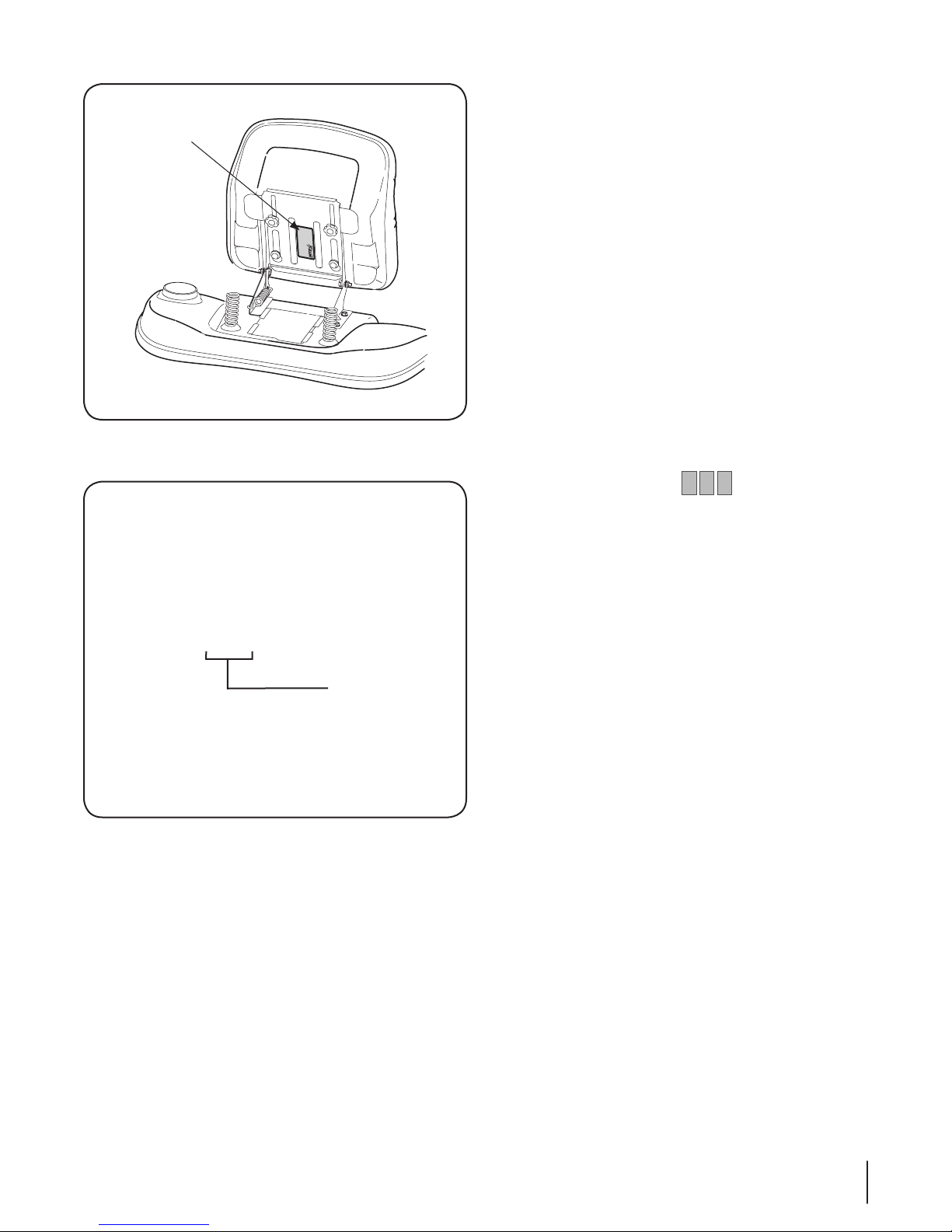
To determine which model of rider you have, you will need to
locate the rider’s model plate, located under the seat. Simply flip
the seat up and locate the model plate, which will consist of an
11 digit/letter model number and a serial number. See Fig. 1-1.
For ease in this installation and for future use, copy your rider’s
model number & serial number below now:
Rider Model Number:__ __ __ __ __ __ __ __ __ __ __
Rider Serial Number:_________________________
Sample Model Number
1 3 A M 7 9 0 G 0 0 0
Indicates Model Series 700
Figure 1-2
The 5th, 6th & 7th numbers from the left in your model number
determine your rider’s model series. See Fig. 1-2.
When you fill in your model number in the space above, the
actual model series number should fall into the gray shaded area.
Now that you have determined what model rider you are
attaching this grass bag collection system to, follow the
instructions on the following pages according to your model of
rider.
3Section 1 — to the owner

Important Safe Operation Practices
WARNING! This symbol points out important safety instructions which, if not followed,
could endanger the personal safety and/or property of yourself and others. Read and follow
all instructions in this manual before attempting to operate this machine. Failure to comply
with these instructions may result in personal injury.
When you see this symbol. HEED ITS WARNING!
DANGER! This attachment was built to be used according to the safe operation practices in
this manual. Carelessness or error on the part of the operator can result in serious injury.
Mowers are capable of amputating hands and feet and throwing objects. Failure to observe
the following safety instructions as well as the instructions provided with your mower, could
result in serious injury or death.
2
General Operation
1. Read, understand, and follow all instructions on your
equipment and in their manuals before attempting to
assemble and operate. Keep this manual in a safe place for
future and regular reference and for ordering replacement
parts.
2. To help avoid blade contact or a thrown object injury, keep
bystanders, helpers, children and pets at least 75 feet from
the mower while it is in operation. Stop machine if anyone
enters the area.
3. Thoroughly inspect the area where the equipment is to be
used. Remove all stones, sticks, wire, bones, toys, and other
foreign objects which could be picked up and thrown by
the blade(s). Thrown objects can cause serious personal
injury.
4. Always wear safety glasses or safety goggles during
operation and while performing an adjustment or repair
to protect your eyes. Thrown objects which ricochet can
cause serious injury to the eyes.
5. Do not operate the mower without the discharge cover
or entire grass catcher in its proper place. A missing
or damaged discharge cover or grass bag attachment
component may result in thrown objects or blade contact
injuries.
6. Do not put hands or feet near rotating parts or under the
cutting deck. Contact with the blade(s) can amputate
hands and feet.
7. Shut off mower’s engine and wait for blades to come to
a complete stop before unclogging mower’s discharge
opening or bagger parts.
8. Slow down before turning. Operate the machine smoothly.
Avoid erratic operation and excessive speed. Be aware
that a grass catcher attachment can affect the handling
characteristics of your mower.
9. Disengage blade(s), set parking brake, stop engine and wait
until the blade(s) come to a complete stop before opening
bagger attachment’s top cover, removing grass catcher,
emptying grass, unclogging chute, removing any grass or
debris, or making any adjustments.
10. Never leave a running machine unattended. Always turn
off blade(s), place transmission in neutral, set parking
brake, stop engine and remove key before dismounting.
11. Your machine is designed to cut normal residential grass of
a height no more than 10”. Do not attempt to mow through
unusually tall, dry grass (e.g., pasture) or piles of dry leaves.
Dry grass or leaves may contact the engine exhaust and/
or build up on the mower deck presenting a potential fire
hazard.
12. If situations occur which are not covered in this manual, use
care and good judgment. Contact your customer service
representative for assistance.
Slope Operation
Slopes are a major factor related to loss of control and tip-over
accidents which can result in severe injury or death. Attachments
can also affect the stability of the machine. All slopes require
extra caution.
For your safety, use the slope gauge included as part of this
manual to estimate the angle of slopes before operating this
machine on a sloped or hilly area. If the slope is greater than 10
degrees as shown on the slope gauge, do not operate the mower
with the grass bag attachment installed on that area or serious
injury could result.
Do:
1. Mow up and down slopes, not across. Exercise extreme
caution when changing direction on slopes.
2. Watch for holes, ruts, bumps, rocks, or other hidden
objects. Uneven terrain could overturn the machine. Tall
grass can hide obstacles.
4
3. Use slow speed. Choose a low enough speed setting so
that you will not have to stop or shift while on the slope.
Tires may lose traction on slopes even though the brakes
are functioning properly. Always keep machine in gear
when going down slopes to take advantage of engine
braking action.
4. Follow the manufacturer’s recommendations for wheel
weights or counterweights to improve stability.
5. Keep all movement on the slopes slow and gradual. Do
not make sudden changes in speed or direction. Rapid
engagement or braking could cause the front of the
machine to lift and rapidly flip over backwards which could
cause serious injury.
6. Avoid starting or stopping on a slope. If tires lose traction,
disengage the blade(s) and proceed slowly straight down
the slope.
Do Not:
1. Do not turn on slopes unless necessary; then, turn slowly
and gradually downhill, if possible.
2. Do not mow near drop-offs, ditches or embankments. The
mower could suddenly turn over if a wheel is over the edge
of a cliff, ditch, or if an edge caves in.
3. Do not try to stabilize the machine by putting your foot on
the ground.
4. Do not use a grass catcher on steep slopes.
5. Do not mow on wet grass. Reduced traction could cause
sliding.
General Service
1. Before cleaning, repairing, or inspecting, make certain the
blade(s) and all moving parts have stopped. Disconnect the
spark plug wire and ground against the engine to prevent
unintended starting.
2. Keep all nuts, bolts, and screws tight to be sure the
equipment is in safe working condition.
3. Never tamper with your mower’s safety interlock system
or other safety devices. Check their proper operation
regularly.
4. Never attempt to make adjustments or repairs while the
mower’s engine is running.
5. Grass catcher components and the discharge cover are
subject to wear and damage which could expose moving
parts or allow objects to be thrown. For safety protection,
frequently check components and replace immediately
with original equipment manufacturer’s (O.E.M.) parts only,
listed in this manual. Use of parts which do not meet the
original equipment specifications may lead to improper
performance and compromise safety!
6. Maintain or replace safety and instruction labels, as
necessary.
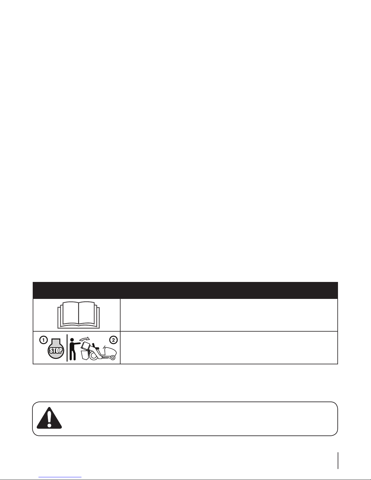
Safety Symbols
This table depicts and describes safety symbols that may appear on this product. Read, understand, and follow all instructions on the
machine before attempting to assemble and operate.
Symbol Description
READ THE OPERATOR’S MANUAL(S)
Read, understand, and follow all instructions in the manual(s) before attempting to
assemble and operate.
STOP
Turn OFF the engine before opening the bagger cover.
WARNING! Your Responsibility—Restrict the use of this power machine to persons who read, understand and
follow the warnings and instructions in this manual and on the machine.
SAVE THESE INSTRUCTIONS!
5Section 2 — important Safe operation practiceS
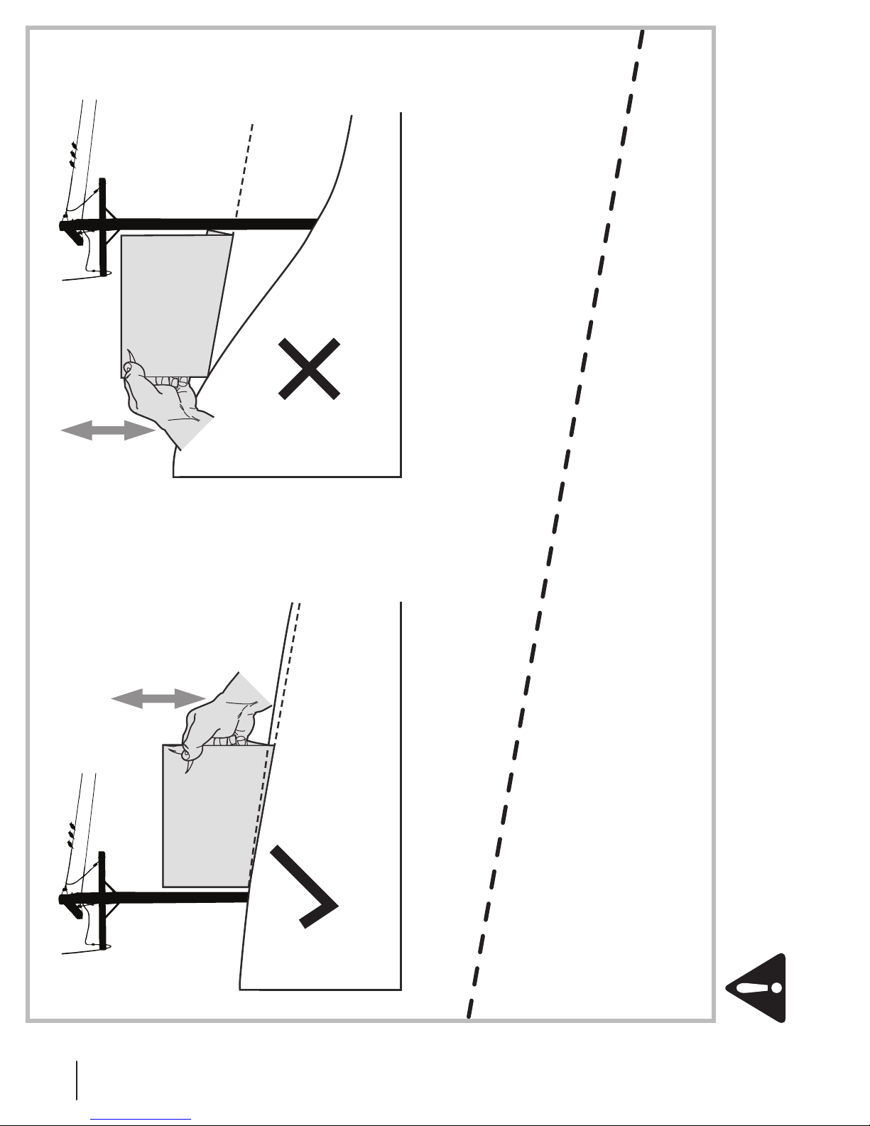
USE THIS SLOPE GAUGE TO DETERMINE
IF A SLOPE IS TOO STEEP FOR SAFE OPERATION!
To check the slope, proceed as follows:
1. Remove this page and fold along the dashed line.
2. Locate a vertical object on or behind the slope (e.g. a pole, building, fence, tree, etc.)
3. Align either side of the slope gauge with the object (See Figure 1 and Figure 2 ).
4. Adjust gauge up or down until the left corner touches the slope (See Figure 1 and Figure 2).
5. If there is a gap below the gauge, the slope is too steep for safe operation (See Figure 2 above).
10° Slope
Figure 2Figure 1
Slope Gauge
10° Slope
(OK) (TOO STEEP)
10° dashed line
Do not operate machine on slopes in excess of 10 degrees. All slopes require extra caution. If you cannot back up the slope
or if you feel uneasy on it, do not mow it. Always mow up and down slopes, never across the face of slopes.
WARNING! Slopes are a major factor related to tip-over and roll-over accidents which can result in severe injury or death.
6 Section 2 — important Safe operation practiceS
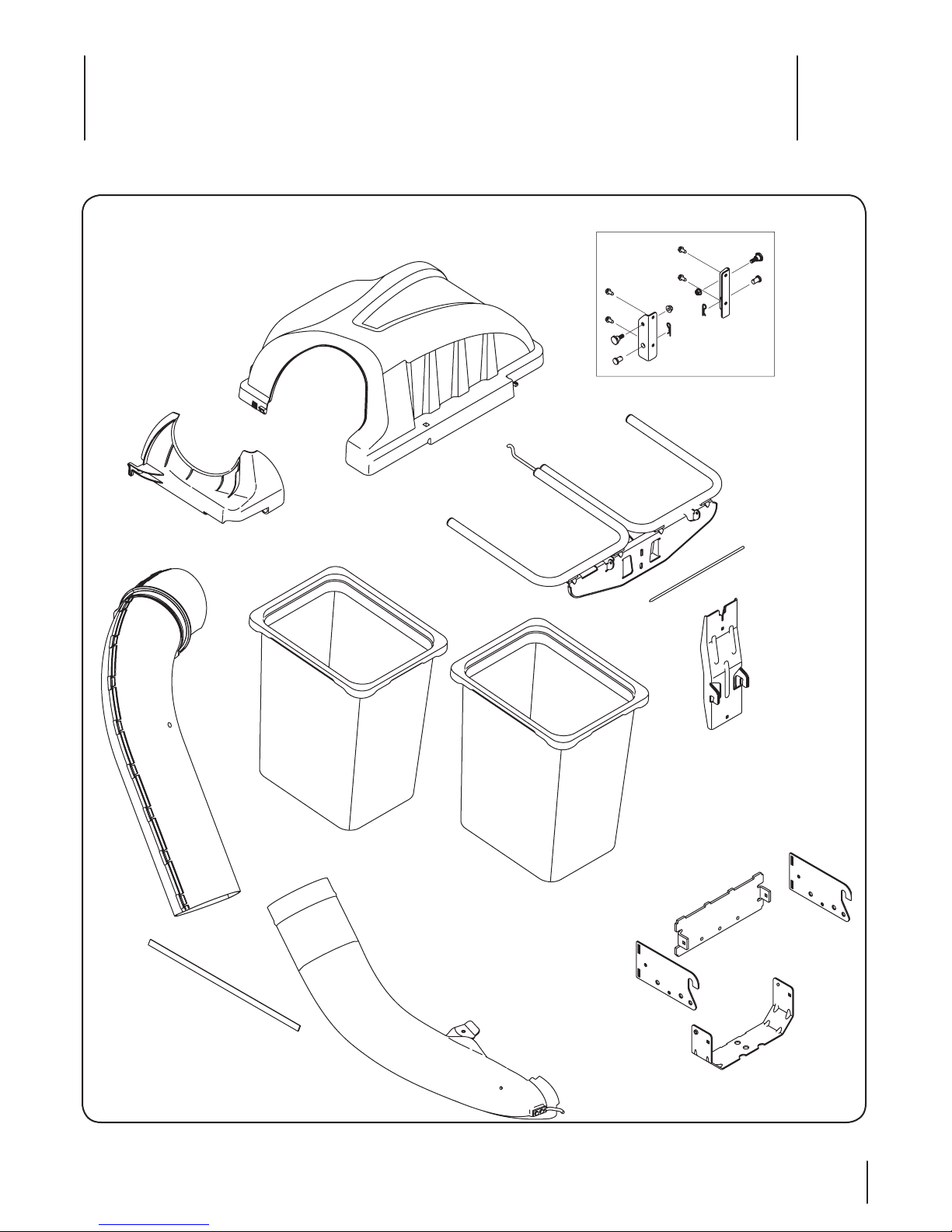
Contents of Carton
3
Before beginning installation, remove all parts from the carton to make sure everything is present. Carton contents are shown below.
Part numbers for this hardware can be found in the Parts List section of this manual.
700 Series Mounting Kit
Grass Catcher
Cover
Upper Chute
Support
Bag Support
Assembly
Upper Chute Tube
Grass Bag
Assemblies
Discharge Chute
Elbow
Hinge Cover Pin
Upright Support
Rear Attachment
Bracket
LH Mount
RH Mount
Self-Adhesive
Foam Strip
Hitch Support
7
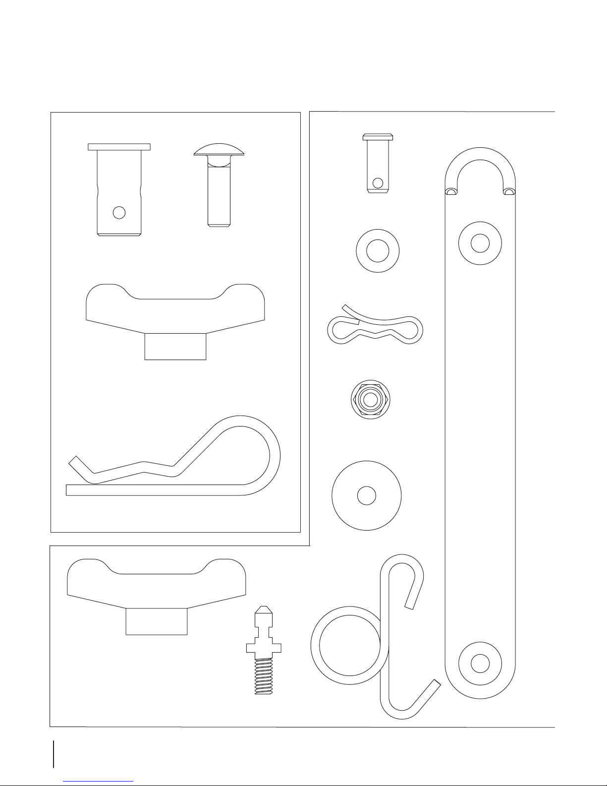
CONTENTS OF HARDWARE PACK
This grass collector kit is shipped with two loose hardware packs enclosed and one hardware pack included in the mounting bracket
kit. Please check your hardware packs against the illustrations below. The quantities for each item is listed in parenthesis.
Hardware Pack for 689-00328A
(1)
(6)
Customer Reference Number 689-00318A
723-04008A
(1)
(1)
711-05063
711-0309A
720-04122
710-0276
714-0117
(6)
(1)
(1)
736-0204
(1)
714-04040
(1)
912-3027
(2)
720-04122
8 Section 3— contentS of carton
(1)
711-05049
(1)
936-0176
(1)
732-04510A
Assembly & Installation
For 700 Models Only! For all other models
4
700 Series Tractors Only
If you are assembling this bagger unit for use on any model
700 series tractor you will need to install the tractor mounting
brackets packed in your bagger kit. If you are installing this
bagger unit on any other tractor, disregard these steps and
move to Assemble Mounting Brackets later in this section. To
determine which model of tractor you are installing this bagger
on, refer to page 3 of this manual.
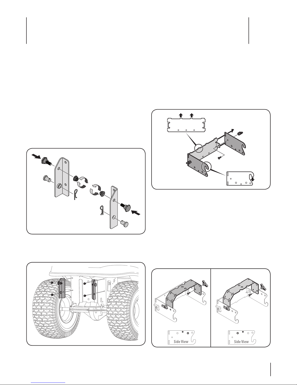
To install these brackets on a model 700 series tractor, follow
these steps:
1. If not already installed by the factory, install a shoulder bolt
from your hardware pack on each bracket, securing them
with flange lock nuts also included in the hardware pack.
Refer to Figure 4-1.
2. If already installed in the brackets, remove the clevis pins
and clips, retain for later instructions. Refer to Figure 4-1.
Figure 4-1
3. Mount the 700 series tractor mounting brackets to your
tractor using four self-tapping hex screws included with
your kit . See Figure 4-2.
Assemble Mounting Brackets
To assemble the bagger mounting assembly, locate the
mounting assembly pack and follow these steps:
1. Attach the two hitch side brackets to the universal rear
attachment bracket using two carriage bolts (710-0276) and
wing knobs (720-04122) from hardware pack 689-00328A.
Note: The hooks on the side brackets should point
downwards and the tabs on the rear plate point upwards as
shown in Figure 4-3.
Figure 4-3
2. Flip over assembly and mount the hitch support bracket to
the mounting assembly as shown in Figure 4-4.
Note: It might be easier during the mounting stage to
leave this hardware only finger tight to facilitate lining up
the hitch hole for the clevis pin. You will be instructed to
tighten this hardware later in this manual.
Note: The holes closest to the mounting hooks are to be
used for all 700 model series machines, while the two holes
closest to the cross mount are for all other models. The
hitch support bracket will need to be flipped to enable
alignment of the proper holes depending on the model of
machine this bagger is being installed on. See Figure 4-4.
Figure 4-2
Figure 4-4
9
Align hole on bracket
with hole on tractor
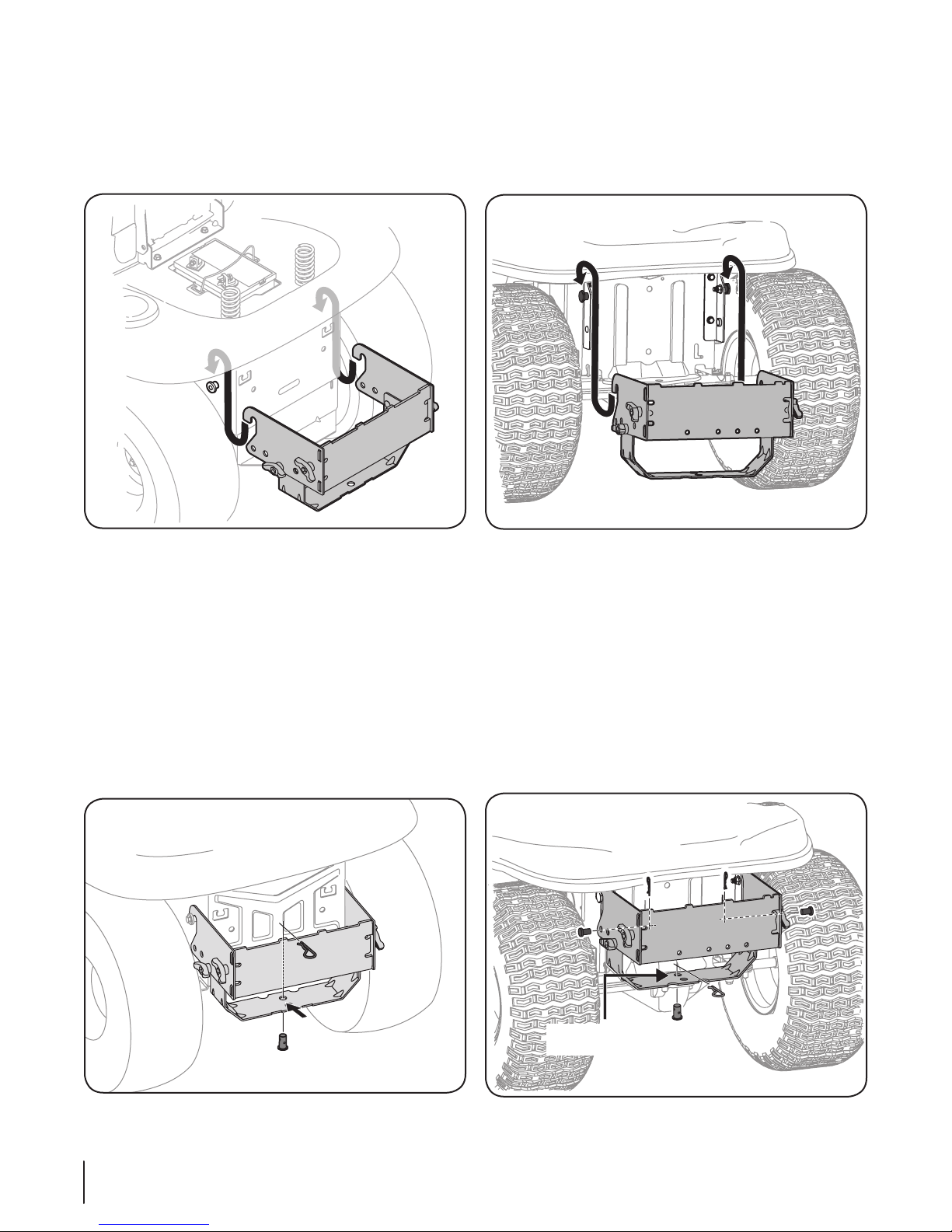
Mount Assembly on Tractor (All Other Tractors)
Align hole on bracket
with hole on tractor
Install mounting assembly onto 900 Series tractors as follows:
1. Place the hooked ends of the mounting assembly over the
shoulder bolts, as in Figure 4-5, on the tractor and line up
the hitch support bracket center hole with the hole on the
tractor’s hitch.
Mount Assembly on Tractor (700 Series Tractors)
1. Place the hooked ends of the mounting assembly over the
shoulder bolts, as in Figure 4-7, on the mounting brackets
previously installed on the tractor and line up the hitch
support bracket center hole with the hole on the tractor’s
hitch.
Figure 4-5
2. Install the clevis pin (711-309A) from hardware pack 68900328A into the tractor’s hitch and secure with a hairpin clip
(714-0117). See Figure 4-6.
Note: The clevis pin can be fed down through the hitch
plate and secured underneath with the hairpin clip, or it
may be easier to feed the clevis pin up through the hitch
plate hole and secure with the hairpin clip on the topside.
Insert the hairpin clip into the top hole, closest to the head
of the pin. You may need to push up on the pin to make the
hole accessible.
Note: If you decided to leave the hitch support only
finger tight during the assembly process, tighten all of the
hardware securely at this time.
Figure 4-7
2. Install the clevis pin (711-309A) from hardware pack 68900328A into the tractor’s hitch and secure with a hairpin clip
(714-0117). See Figure 4-8.
Note: The clevis pin can be fed down through the hitch
plate and secured underneath with the hairpin clip, or it
may be easier to feed the clevis pin up through the hitch
plate hole and secure with the hairpin clip on the topside.
Insert the hairpin clip into the top hole, closest to the head
of the pin. You may need to push up on the pin to make the
hole accessible.
3. Install two clevis pins through the mounting assembly and
secure to the 700 series mounting brackets installed earlier
with click pins provided in the hardware pack. See Figure 4-8.
Figure 4-6
10 Section 4 — ASSembly & inStAllAtion
Figure 4-8
1
2
Note: If you decided to leave the hitch support only
finger tight during the assembly process, tighten all of the
hardware securely at this time.
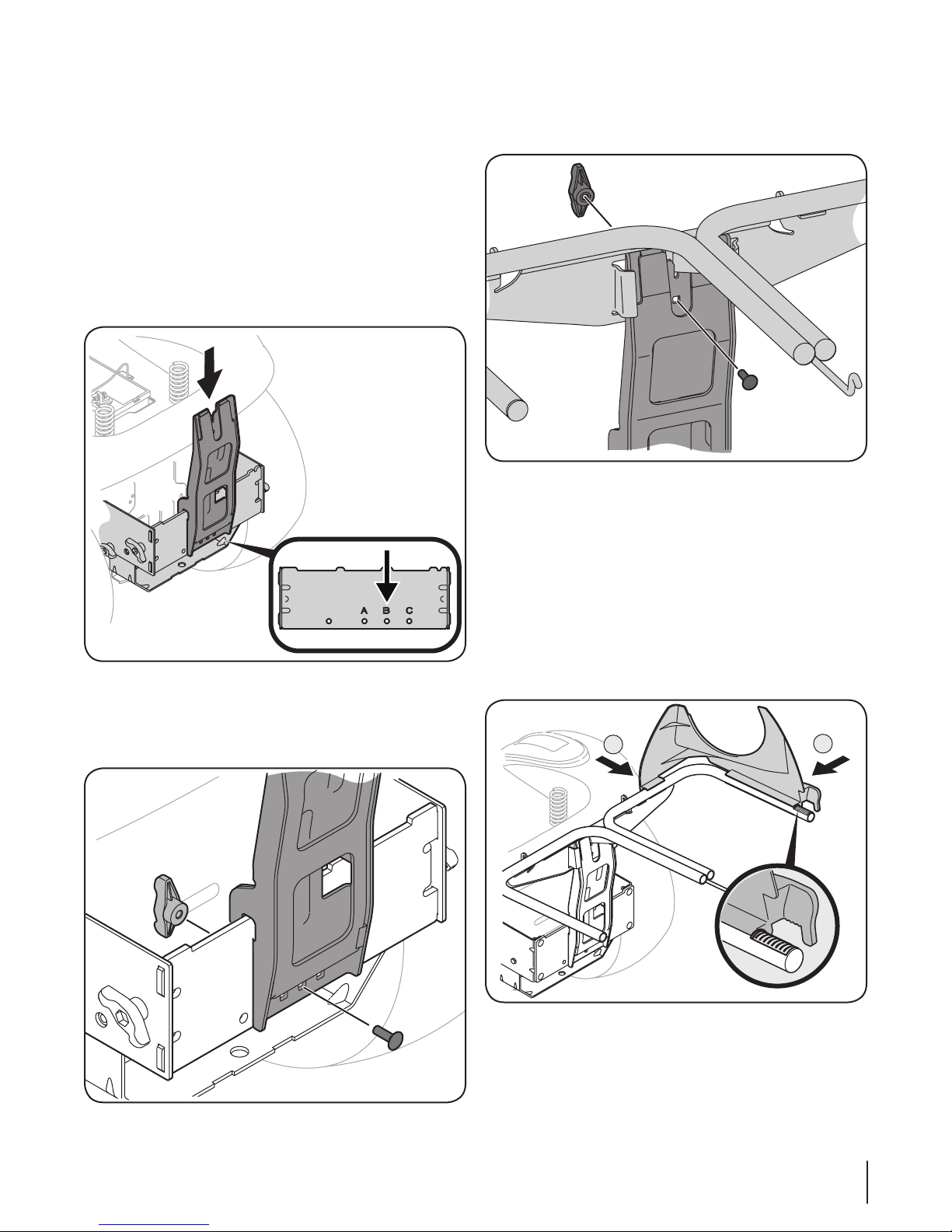
Install the bagger hanger assembly
1. Install the upright support bracket onto the mounting
assembly on the tractor by hooking it over the cross
mounting bracket. See Figure 4-9.
2. Align the upright support bracket with the mounting hole
that best suits the deck size of your machine.
Note: Hole “B” suggested for 42” decks, and Hole “C”
suggested for 46” decks. Some kits may contain plates with
deck size suggestions instead of letters.
Figure 4-9
3. Secure the bag support assembly to the mounting
assembly using a carriage bolt (710-0276) and wing knob
(720-04122) from hardware pack 689-00328A. See Figure
4-10.
4. Install the hanger assembly onto the upright support
bracket using a carriage bolt (710-0276) and wing knob
(720-04122) from hardware pack 689-00328A. See Figure
4-11.
Figure 4-11
Assembling Remaining Bagger Components
Now that the mounting brackets are assembled and are in place
on the tractor, follow these steps to assemble the remaining
bagger components.
1. Snap the plastic upper chute support in place by first
clipping the side portion onto the bagger support rail with
the edge of the snap feature aligned with the red line, as
shown in Figure 4-12.
2. Snap the front side of the chute support to the rail, as
shown in 2 of Figure 4-12.
Figure 4-10
Figure 4-12
11Section 4 — ASSembly & inStAllAtion
1
2
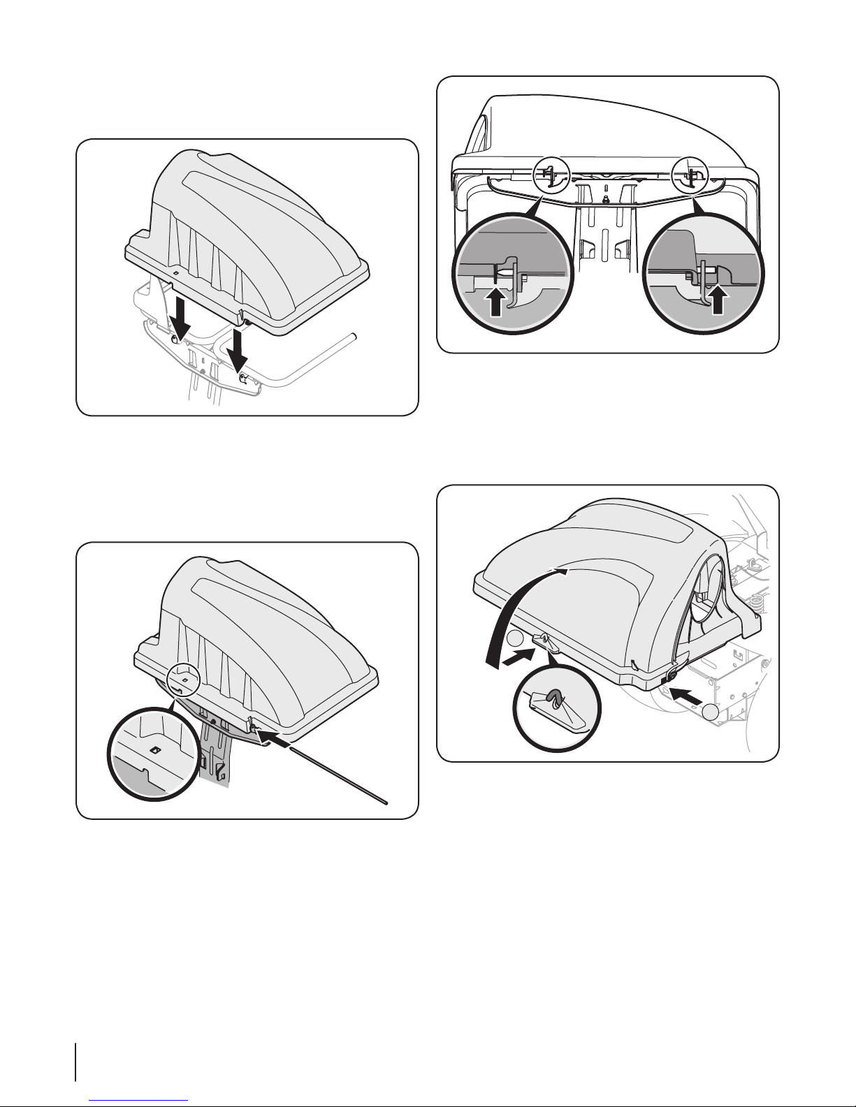
3. Install the grass catcher cover onto the bag support
assembly, as shown in Figure 4-13. The grass catcher cover
goes inside of the two mounting tabs on the bag support
assembly.
Figure 4-13
4. Slide the hinge pin into the hole located on the mounting
tab, as in Figure 4-14. Use the cut-out window (See inset in
Figure 4-14) to line up the hinge pin on the other side and
push pin all the way in until it reaches the end-stop. At this
point the pin clips into place and is secured by a tab in the
bagger cover. See Figure 4-15.
Figure 4-15
5. If not already flipped forward, flip seat forward to allow for
the grass bags and upper tube assembly steps.
6. Open bagger cover by pushing in on the rear, right-side
tab with your right hand, as shown in (1) of Figure 4-16, and
lifting the cover with your left hand in the center rear of the
bagger cover, (2).
Figure 4-14
12 Section 4 — ASSembly & inStAllAtion
Figure 4-16
1
2
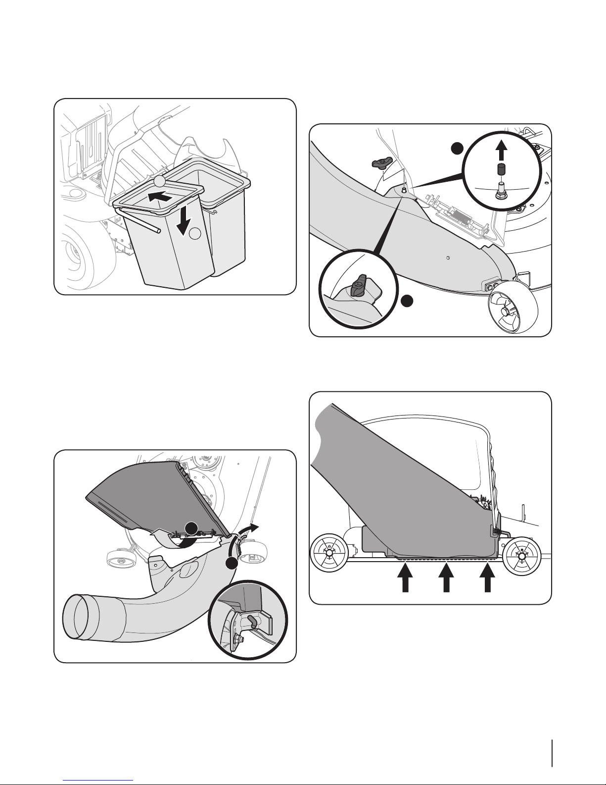
7. Install both grass bag assemblies, with the tight mesh sides
1
2
1
2
facing forward, onto the bag support brackets by inserting
the front edge in first, as shown in Figure 4-17, and setting
the back edge down until it fits into the assembly.
Figure 4-17
Installing the Deck Chute
Note: Determine if your deck is a newer model, or an older
model. Refer to the upper inset of Figure 4-19. If your deck
has a mounting stud present, then you have a newer deck
model and you would follow the instructions below. If no
stud is present, refer to the instructions titled On Tractors
With Older Deck Configurations later in this section.
1. With the tractor’s discharge chute raised up and held open (1),
install the chute elbow by placing the chute elbow mounting
rod into the hole provided in either your deck wheel bracket
or chute mounting tab (2), as shown in Figure 4-18.
2. Secure the chute elbow to the deck using the wing knob
720-04122 from hardware pack 689-00319A. See Figure
4-19.
Note: If present, remove the protective cap off of the
mounting stud on the mowing deck as shown in the upper
inset of Figure 4-19.
Figure 4-19
IMPORTANT: Be certain that the bottom of the discharge
chute is located inside of the lip of the deck opening, as shown in
Figure 4-20.
Figure 4-18
Figure 4-20
13Section 4 — ASSembly & inStAllAtion
On Tractors with Older Deck Configurations
Remove Boot Mounting Rod
2
3
1
1
2
3
Flange
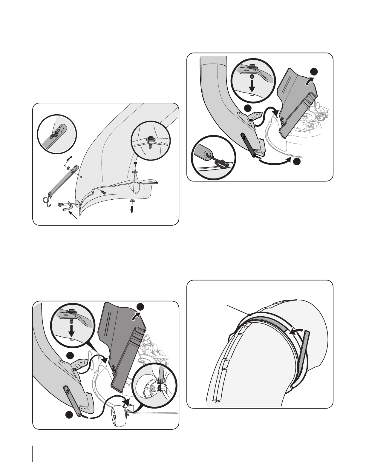
1. Install the rubber chute strap, from hardware pack
689-00318A, onto the chute elbow using the clevis pin (711-
05063), washer (736-0204) and Bow-tie cotter pin (714-04040)
from the hardware pack. See Figure 4-21. Secure the end of
the strap utilizing the hole furthest from the end, insert the
torsion spring hook (732-04510A) into the other end.
Note: On decks with front deck wheels, the boot mount
rod must be removed in order to install this discharge chute
elbow onto the tractor. See Figure 4-21.
Note: On decks without deck wheels, hook the retainer
strap into the hole provided in the flange on the front-side
of the cutting deck. See Figure 4-23.
Figure 4-23
IMPORTANT: Be certain that the bottom of the discharge chute
is located inside of the lip of the deck opening, as previously
shown in Figure 4-20.
Figure 4-21
2. Install the deck mounting pin (711-05049) up into the chute
elbow using two flat washers (936-0176) from hardware pack
689-00318A and secure with a flange lock nut (912-3027), as
shown in Figure 4-21.
3. With the tractor’s discharge chute raised up and held open
(1 of Figure 4-22), install the chute elbow over the chute
opening by placing the deck mounting pin in the hole
provided (2), then secure the elbow to the deck by hooking
the retainer strap torsion spring hook over the deck wheel
mounting bracket a shown in (3) of Figure 4-22.
Installing the Upper Chute Tube
NOTE: Check the upper chute for a cardboard insert installed
for shipping purposes. If the insert is present, remove it before
continuing with Step 1.
1. Peel the backing off of the self-adhesive foam strip (721-
04388) that has been included within your Contents of
Carton. Apply it to the upper chute, flush against the flange
as shown in Figure 4-24.
14 Section 4 — ASSembly & inStAllAtion
Figure 4-22
Figure 4-24
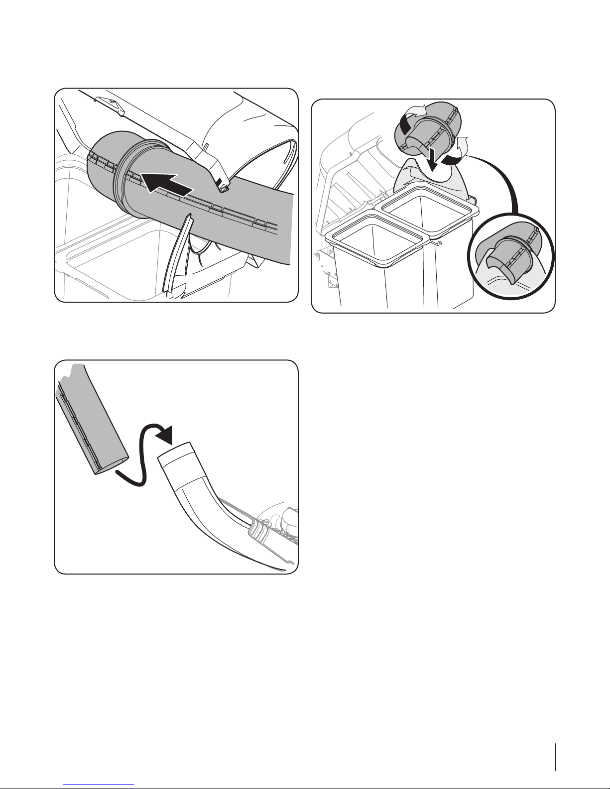
2. With the grass catcher cover open, install the upper
discharge chute through the discharge chute opening, as
shown in Figure 4-25.
Figure 4-25
3. With the ability now to wiggle the discharge chute tube
back and forth, slide it over the chute elbow mounted on
the cutting deck, as shown in Figure 4-26.
4. Continue to work the discharge chute down over the chute
elbow until the groove on the discharge chute aligns with
the upper chute support, as shown in the inset of Figure
4-27.
Figure 4-27
5. Close the grass catcher cover.
Figure 4-26
15Section 4 — ASSembly & inStAllAtion
Operation
1
2
2
1
5
Bagger Usage
NOTE: When both grass bags are full, place the tractor on a firm,
level surface, disengage the PTO, turn the tractor engine off and
set the parking brake.
1. Flip Seat up.
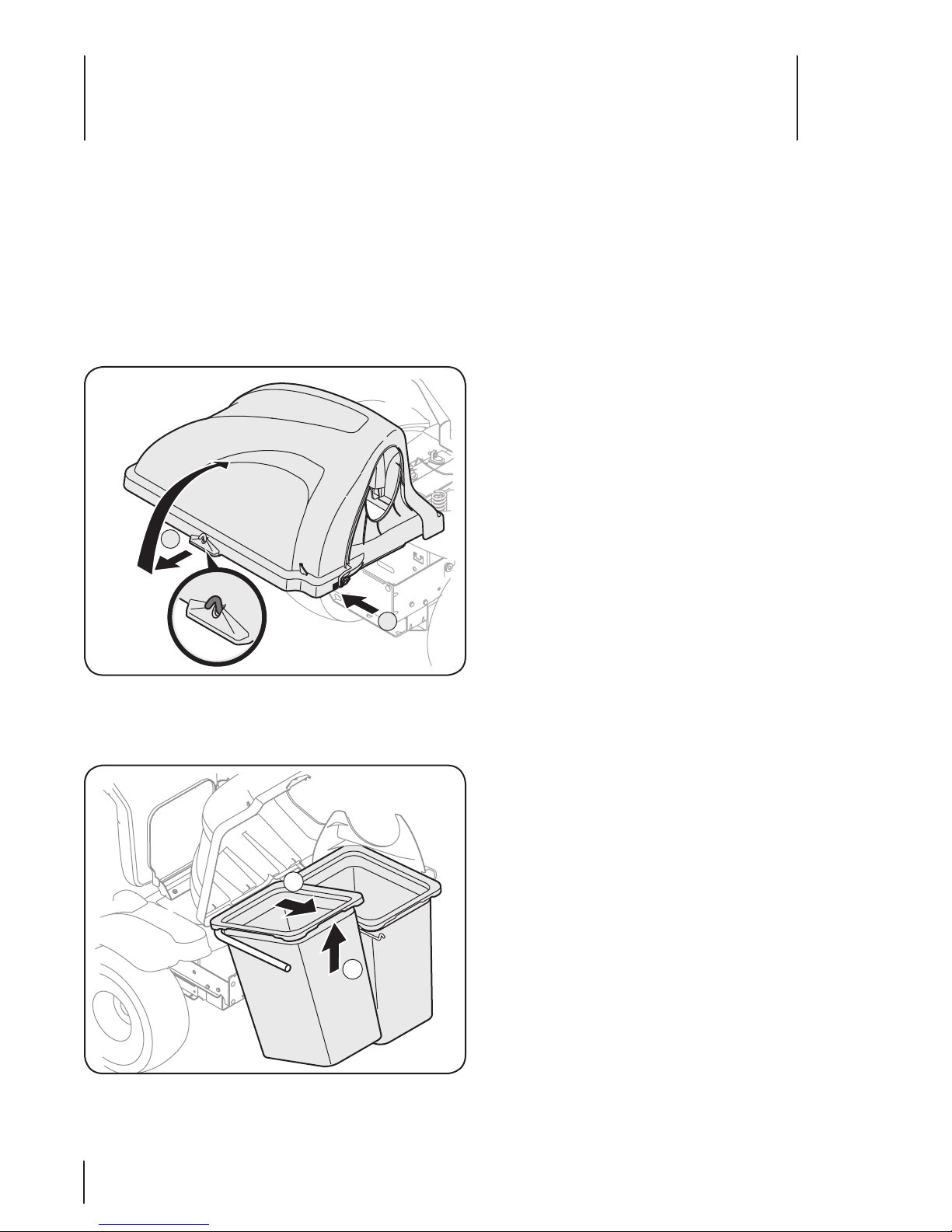
2. Open the grass bag cover by pushing in on the rear, rightside tab with your right hand, as seen in 1 of Figure 5-1, and
lifting the cover with your left hand in the center rear of the
bagger cover, 2. Do not remove the chute tube assembly
from the tractor.
4. Empty the grass clippings at a proper disposal sight, use
the handle at the bottom of each grass bag. Holding the
bag firmly, empty the contents
5. Replace the grass bags in the reverse order and in the same
orientation in which they were removed, close the lid, pivot
the seat down, restart your tractor and resume cutting your
grass.
6. Retighten all wing knobs periodically throughout the
season.
Figure 5-1
3. Remove the grass bags by lifting these up (1 in Figure 5-2)
and moving the bags away from the bag support assembly
(2).
Figure 5-2
16

Notes
6
17
 Loading...