

MTD 195-746-000 User Manual
OUTDOOR POWER EQUIPMENT
for all seasons
.75
28” TILLER
ATTACHMENT
Important:
Read
Instructions Carefully
PRINTED IN U.S.A.
Model Numbers
195-746-000
19746S
TM0-33603B
Thank you for purchasing
an American-built product.
J
FORM NO. 770-4235

r
♦
♦
4
4
4
4
4
4
LIMITE:D WARRANTY
For one year from the date of original retail purchase, MTD PRODUCTS INC wiii either
repair or replace, at its option, free of charge, F.O.B. factory or authorized service firm, any
part or parts found to be defective in material or workmanship. Transportation charges for
the movement of any power equipment unit or attachment are the responsibility of the pur
chaser. Transportation charges for any parts submitted for replacement under this warran
ty must be paid by the purchaser unless such return is requested by MTD PRODUCTS INC.
This warranty will not apply to any part which has become inoperative due to misuse, ex
cessive use, accident, neglect, improper maintenance, alterations, or unless the unit has
been operated and maintained in a :cordance with the instructions furnished. This warran
ty does not apply to the engine, motor, battery, battery chargeror component parts thereof.
Please refer to the applicable manufacturer’s warranty on these items.
4
4
4
4
4
4
4
\
4
4
4
4
4
4
V
This warranty will not apply where the unit has been used commercially.
Warranty service is available throu jh your local authorized service dealer or distributor. If
you do not know the dealer or distri cutor in yourarea, please write to the Customer Service
Department of MTD.
The return of a complete unit will r ot be accepted by the factory unless prior written per
mission has been extended by MTD.
This warranty gives you specific kgal rights. You may also have other rights which vary
from state to state.
4
4
4
4
4
4
J

FIGURE 1
ASSEMBLY INSTRUCTIONS
NOTE
Right and left hand side of the unit
is determined from the driver's seat,
facing forward.
• Contents of Hardware Pack (See figure 1):
A
B
C
D
E
F
G
H (1)
I (1)
J (5)
M (1)
N (2)
O (3)
P (1)
Q (1)
Extension Spring
(1)
Flat Washer 1/2" I.D. x 1-1/2" O.D.
(1 )
Flat Washer 5/8" I.D. x 1-1/4" O.D.
(1)
Flat Washers 1/2" I.D. x 1" O.D.
(2)
Hex Bolts 3/8-24 x 7/8" Long
(4)
Lock Washers 3/8" I.D.
(4)
Hex Nuts 3/8-24 Thread
(4)
Hex Bolt 5/16-24 x 1" Long
Spirol Pin
Hairpin Cotters
Hex Bolt 5/16-24 x 1-1/2" Long
Lock Washers 5/16" l;D.
Hex Nuts 5/16-24 Thread
Ferrule
Spacer 1/2" I.D. x 1" O.D. x 1/2" Long
FIGURE 2
-Loose Parts in Carton (See figure 2):
R (1) Carriage Bracket Assembly
S (1) Idler Bracket Support Arm Assembly
T (2) Support Pivot Brackets
U (1) Compression Spring
V (1) Idler Bracket Assembly
W (1) Lift Rod Assembly
1. Remove the cutting deck from your tractor if
one is attached.
2. Preassemble the idler bracket support arm (S) to
one support pivot bracket (T> and idler bracket
assembly as follows.
A. Place the idler bracket support arm through
the hole in support pivot bracket as shown in
figures 3 and 4.
FIGURE 3
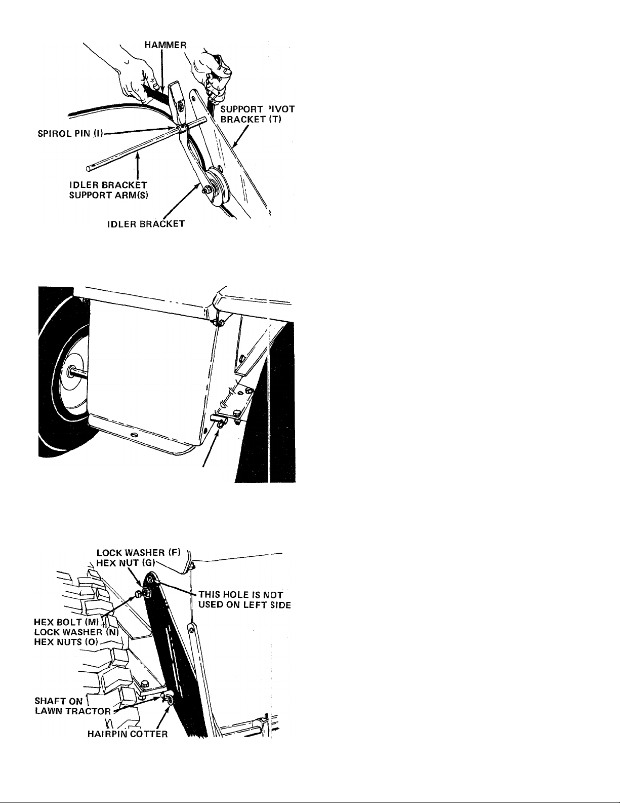
FIGURE 4
ASSEMBLY (V)
B. Next, slide the idler bracket assembly (V)
over the idler bracket support arm. Secure
with spirol pin (I). See figure 4.
3.
Remove the two hairpin cotters on the rear of
your tractor. See figure 5. These will be re
assembled to your unit in steps 4 and 9.
Place the support pivot bracket (with idler bracket
and support arm attached) in position on the
rear left hand side of tractor. Place large hole in
pivot bracket over shaft on tractor. Secure with
one hairpin cotter removed in step 3.
FIGURE 5
FIGURE 6
HEX BOLT (E)
HAIRPIN
COTTER
5.
Thread one hex nut (O) all the way onto hex
bolt(M) (1-1/2" long).
Place the support pivot bracket in position so the
6.
forward hole (larger) in the bracket aligns with
the larger hole in the tractor frame.
7.
Secure the support pivot bracket to the tractor
by placing hex bolt (M) (with nut assembled) in
the smaller hole in plate which aligns with hole
on tractor. Start hex nut (0) and lock washer
(N) by hand. See figure 6.
Place one hex bolt (E) through top forward
8.
hole in bracket and tractor frame. Secure with
lock washer (F) and hex nut (G).
Assemble the other support pivot bracket to
9.
the right hand side of tractor in the same manner,
except use hex bolt (H) (1" long) instead of the
longer hex bolt and the extra hex nut.
10. Tighten securely all four nuts and bolts which
were used in assembly of pivot support brackets.
11. Secure end of idler bracket support arm assembly
on the right side of tractor with one flat washer
(D) and hairpin cotter (J).

12. Place carriage bracket assembly (R) in position
beneath the running board support rod on the
tractor. Secure each side of carriage bracket to
frame with hex bolts (E), lock washers (F) and
hex nuts (G). Tighten securely. See figure 7.
13. Remove the round belt guard from the idler on
tractor by removing the hairpin cotter. See figure
- 8.
FIGURE 9
14. Unscrew the "L" bolt and swing the wire belt
guard on the engine pulley forward. See figure 9.
 Loading...