

Page 1

10*
ROTARY TILLER
FOR
GARDEN TRACTORS
Model Nos.
192-766,193-966-760
and 193-967-7^0
For one year from date of purchase, MTD Products Inc,
will replace for the original purchaser, free of charge, F.O.B.
factory or authorized service firm, any part or parts found to
be defective in material or workmanship. All transportation
charges on parts submitted for replacement under this war
ranty must be paid by the purchaser. This warranty does not
include replacement of parts which become inoperative
through misuse, excessive use, accident, neglect, improper
maintenance or alterations by unauthorized persons. This
warranty does not include the engine, motor, battery, bat
tery charger or any component parts thereof. For service on
these units refer to the applicable manufacturer's warranty.
The above warranty will apply only to the original owner
and will be effective only if the warranty card has been pro
perly processed. It will not apply where the unit has been
used commercially.
Warranty service is available through your local author
ized service dealer or distributor. UNDER NO CIRCUM
STANCES WILL THE RETURN OF A COMPLETE UNIT
BE ACCEPTED BY THE FACTORY UNLESS PRIOR
WRITTEN PERMISSION HAS BEEN EXTENDED.
Your rotary tiller is a precision built machine designed to
to take the work out of gardening and other related chores. It
can be used for seed b<Kj preparation, titling, cultivating, fur
rowing, composting and mulching. Like any other piece of
power equipment, it n»quires a certain amount of care and
maintenance. In return For this, it will give a maximum of ser
vice and efficiency. Read these instructions carefully before
assembling or operating your tiller. Through proper care and
operation, you will obtain long, efficient service and trouble
free operation.
1. Your tiller is a precision piece of power equipment. Exer
cise extreme caution at all times.
2. Do not attempt to start engine with the clutch control in
engages or "Forward" position.
3. Stand clear of tines when starting engine. Never stand in
front of, or work on tines while the engine is running.
4. NEVER place hands or feet in the vicinity of the tines
while the engine is running.
5. Always stop engine iMien tiller is not in actual use.
6. Always disconnect spark plug wire during repairs or re
fueling operations.
7. Do not fill gas tank white engine is running. Do not spill
gasoline on hot engine.
MTD PRODUCTS INC
5389 WEST 130th STREET
P.O.BOX 2741 CLEVELAND OHIO 44111
FORM NO. 770-3844
Page 2

192- 766 Tiller Attachment is for 10, 12, and 14 HP Tractors built before
1971.
193- 966 Tiller Attachment is for the 1971 through 1973 10, 14, 15 and 16
HP Tractors. (Models 141-760, 141-960, 142-760, 142-960, 143-860 and
143-960).
193-967 Tiller Attachment is for the Hydrostatic Tractors. (Model 141-900,
142,990 and 143-990).
ASSEMBLY INSTRUCTIONS FOR
MODELS
193-966 and 193-967. (Refer to Fig. 2)
1. Assemble outer tine assemblies complete to the
inner tine assemblies complete with four spirol
pins 5/16 diameter x 2-1/2^’ long Heavy Duty.
(Ref. 28).
2. Assemble pivot bracket assembly (Ref. 24) to the
power input side of the gear case with two bolts
5/8-11 X 1-1/2” long (Ref. 67) and lockwashers
5/8 diameter (Ref. 25).
3. Assemble other pivot bracket assembly (Ref. 24)
to the right hand side of gear case.
4. Assemble the universal drive shaft assembly (Ref.
26). To the gear case with spirol pin (Ref. 22).
Drive pin into the shaft with a hammer. The end of
the universal drive shaft assembly with the square
head set screw attaches to the power take off on
tractor.
5. Assemble cover bracket (Ref. 20) to cover bracket
assembly (Ref. 5) with one carriage bolt 1-1/2” long
(Ref. 15).
6. Assemble cover bracket assembly (Ref. 5) to cover
assembly (Ref. l)with six carriage bolts 5/16—18x1”
long (Ref. 4) lockwashers 5/16 diameter (Ref. 6) and
nuts 5/16-18 thread (Ref. 7). Assemble bolts and
nuts loose until all six are started, then tighten.
ASSEMBLY INSTRUCTIONS
FOR MODEL
192-766. (Refer to Figs. 1 and 2)
1. Assemble outer tine assemblies complete to the
inner tine assemblies complete with four spirol
pins 5/16 diameter x 2-1/2’’ long Heavy Duty.
(Ref. 28).
2. Assemble flat bracket L.H. (Ref. 69) to the power
input side of the gear case with two bolts
5/8—11 X 1-1/2” long (Ref. 67) and lockwashers
5/8 diameter (Ref. 25).
3. Assemble offset bracket R.H. (Ref. 68) to the right
hand side of the gear case with two bolts
5/8-11 X 1-1/2” long (Ref. 67) and lockwashers 5/8
diameter (Ref. 25).
4. Assemble the universal drive shaft assembly (Ref.
26) to the gear case with spirol pin (Ref. 22).
Drive pin into the shaft with a hammer. The end
of the universal drive shaft assembly with the
square head set screw attaches to the power take
off on the tractor.
5. Assemble cover bracket (Ref. 5) to the cover
assembly (Ref. l)with sixcarriage bolts 5/16—18x1”
long (Ref. 4), lockwashers 5/16 diameter (Ref. 6)
and nuts 5/16—18 thread (Ref. 7). Assemble
bolts and nuts loose until all six are started, then
tighten.
7. Assemble cover and bracket assembly to gear case
with four bolts 1/2-13 X 7/8 long. (Ref. 9) and lock
washers 1/2 diameter (Ref. 10). Assemble bolts
loose until- all four are started, then tighten.
8. Remove the solid pipe plug in the hole above the
input shaft in the gear case and replace it with the
vented pipe plug (Ref. 21). Refer to Figure 2 for
proper location of the vented plug. This vented plug
allows the gear case to breathe.
9. The lubricant level in the gear case should be
checked after it is attached to the tractor.
6. Assemble cover and bracket assembly to the gear
case with four bolts 1/2—13 x 7/8 long (Ref. 9) and
lockwashers 1/2 diameter (Ref. 10). Assemble bolts
loose until all four are started, then tighten.
7. Remove the solid pipe plug in the hole above the
input shaft in the gear case and replace it with the
vented pipe plug (Ref. 21). Refer to Figure 2 for
proper location of the vented plug. This vented
plug allows the gear case to breathe.
8. The lubricant level in the gear case should be
checked after it is attached to the tractor.
Page 3
ATTACHING YOUR ROTARY TILLER TO YOUR
TRACTOR (Models 193-966 and 193-967)
1. Before attaching your rotary tiller to your tractor, be
sure the rear wheels on the tractor are all the way
into the minimum rear wheel width. Refer to your
tractor manual.
2. Remove the draw bar assembly from the three point
hitch of your tractor by removing the two cotterhairpins.
3. Place the rotary tiller behind the tractor in the
approximate position shown in Fig. 2.
4. Attach universal drive shaft (Ref. 26) to the tractor
power take off. Tighten set screw (Ref. 27).
5. Move the lift lever on the tractor until the draft bar
assemblies line up with pivot brackets (Ref. 24).
6. Assemble pivot brackets (Ref. 24) to the rear of the
tractor with washers and cotter-hairpins.
ATTACHING YOUR ROTARY TILLER TO YOUR
TRACTOR (Model 192-766).
1. Before attaching your rotary tiller to your tractor, be
sure the rear wheels on the tractor are all the way
into the minimum rear wheel width. Refer to your
tractor manual.
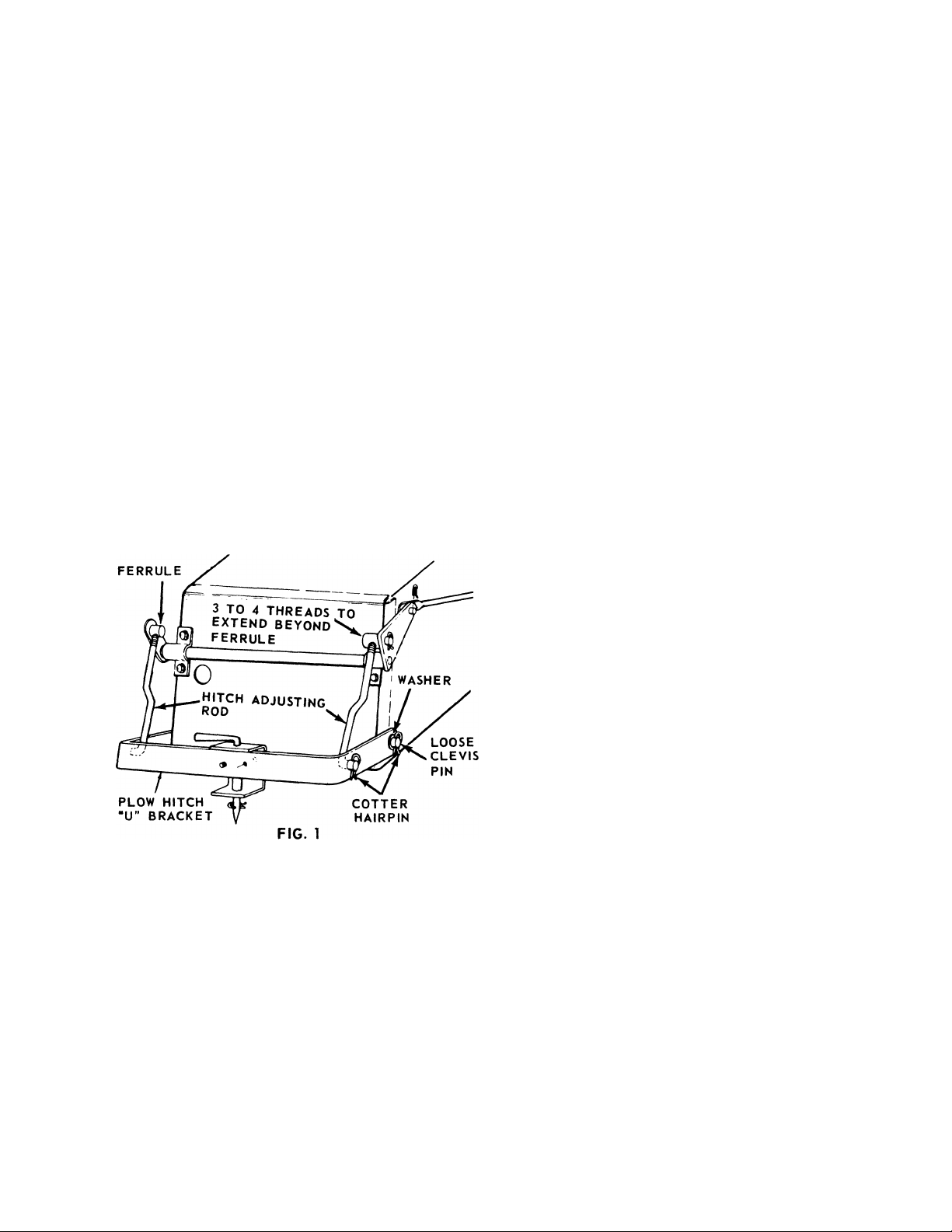
Remove the part of the plow hitch from your
2.
tractor by removing the two cotter-hairpins on the
loose clevis pins and the two cotter-hairpins from
the hitch adjusting rods. Refer to Fig. 1.
Lift the rotary tiller with the lift h^^adle on the tractor
to transport it to and from the work area. Use caution
when transporting the rotary tiller since your ground
clearance has been reduced.
The entire tiller unit is offset to the left to allow
closer tilling with the left side.
NOTE: BE SURE THE POWER TAKE OFF HANDLE
IS IN THE ‘‘OFF” POSITION BEFORE STARTING
THE TRACTOR ENGINE. Refer to the tractor manual
for proper position of the PTO handle.
GENERAL ROTARY TILLER OPERATION
ALWAYS shut the engine off when removing a stone or
anything that becomes entangled in the tines.
All large stones or rocks should be removed from the
area before you begin tilling.
Tilling can be done with or without the outer tine
assemblies. You can till 32!/2” wide with the outer tines
and 17” wide with only the inner tines.
Use rear wheel weights when tilling. Part number
191-776.
Maximum tilling depth is approximately 10” depending
on the type of soil. This CANNOT be accomplished in
one pass. Maximum tilling depth may be only 2-1/2”
on extremely hard soil on the first pass.
The more passes you make with the tiller over the same
area, the deeper you can till and the finer you pulverize
the soil. Change directions as often as you can to level
out the ground and to prevent furrows.
When tilling, the tiller will push the tractor and the
transmission on the tractor will hold the tractor back.
For easy lifting of the rotary tiller from the ground, shut
off the power by disengaging the PTO handle and
continue to drive the tractor forward. The tines will
climb out of the hole when you pull the lift lever
handle back.
3. Adjust the hitch adjusting rods until 3 or 4 threads
extend beyond the rear hitch ferrule.
4. Place the rotary tiller behind the tractor in the
approximate position shown in Fig. 2.
5. Attach universal drive shaft (Ref. 26) to the tractor
power take off. Tighten set screw (Ref. 27).
6. Assemble brackets (Ref. 68 & 69) to the rear of the
tractor with the loose clevis pins, washers and
cotter-hairpins.
CHECK LUBRICANT LEVEL at this time. The gear
case is lubricated at the factory but should be checked
for proper lubricant level before each operation. Remove
plug (Ref. 61) on side of gear case. Lubricant should
be at this level, if not, fill through the vented pipe plug
hole (Ref. 21) with SAE 140 oil until the lubricant over
flows through the hole in the side of the gear case.
Replace the pipe plugs. BE SURE THE VENTED PIPE
PLUG IS IN THE OIL FILL HOLE. Refer to Fig. 3.
LUBRICATION
Gear Case - Lubricated with three quarts of SAE 140
oil. It is lubricated at the factory. Be sure to check
the lubricant level before each use.
To check the oil level, remove plug (Ref. 61) on the
side of the gear case. See Fig. 3. Lubricant should be
at this level. If not, fill through the vented pipe plug
hole (Ref. 21) until it overflows through the hole in
the side of the gear case. Replace both plugs. BE
SURE THE VENTED PIPE PLUG IS IN THE OIL
FILL HOLE.
Grease Fittings — There are three grease fittings on
the universal drive shaft assembly. Lubricate after
each 25 hours of use with an automotive multi-purpose
type grease. Apply grease with grease gun provided
with your tractor. Lubricate until the old grease is
pushed through and clean grease appears.
Page 4

Used on Gear driven Tractors
ROTARY TILLER 192-766, 193-966 and 193-967
FOR MODEL
192-766
FIG. 2
901-10507
OUTER TINE ASS Y.
L M(COMPLETE)
901-1050 6
OUTER TINE
ASSY. RH
(COMPLETE)
Page 5

ROTARY TILLER 192-766, 193-966 and 193-967
Oil level should be checked when the tiller Is
mounted on the tractor with the tines touching
the ground.
Place a 6 inch block under the front of the case
to check oil level with the tiller off the tractor.
FIG. 3
Page 6

PARTS LIST FOR TILLER ATTACHMENT MODELS 192-766, 193-966 and 193-967
Ref.
No.
10
11
12 742-110
13
14
15 710-431
16
17
18
19 10501
20
21
22 715-118
23
24
25 736-158
26 717-149
27 710-357
28 715-113
29 714-123
30
31
32
33
Part
No.
1 9844A
2
714-111
3 9846
4
710-276
5
10981
6 736-119
712-267
7
8 9850
710-365
9
736-921
712-267
742-113
10502
712-711
736-169
710-113
10984
737-102
712-798
10982
717-184
711-451
719-145
736-124
721-109
Color
Code
Cover Assembly
Cotter Pin 3/32 Dia. x V Lg.*
Cover Flap Assembly
Carriage Bolt 5/16—18 x V’ Lg. *
Cover Bracket Assembly
Spring Lockwasher 5/16 Scr. *
Hex Nut 5/16-18 Thread *
Rod
Hex Hd.Cap Scr.1/2-13 x 7/8" Lg.*
Spring Lockwasher 1/2—13 Thread *
Hex Nut 5/16-18 Thread *
Tine R.H. Slasher
Tine L.H. Slasher
Extension - Tine
Carriage Bolt 3/8—16 x 1-1/2”Lg.*
Hex Nut 3/8-24 Thread ^
Spring Lockwasher 3/8 Scr. *
Hex Hd.Cap Scr.3/8—24 x 1-5/8"' Lg.*
Mounting Tine 52
Cover Bracket (966 and 967 only)
Square Hd. Pipe Plug w/Vent 3/8 Thd.
Spirol Pin 5/16 X 1-3/4" Lg. *
Hex Nut 3/8-16 Thread *
Pivot Bracket Assembly
(966 and 967 only)
Spring Lockwasher 5/8 Scr. *
Universal Drive Shaft Assembly
(766 and 966 only)
Universal Drive Shaft Assembly
(967 only) 63
Square Hd.Set Scr.3/8-16 x 1/2" Lg.* 64
Spirol Pin 5/16"Dia.x 2-1/2"Lg. 65
Heavy Duty
Square Key 5/16 x 2" Lg. *
Shaft
Tiller Gear Case - L.H.
Felt Dust Pad - Small
Oil Seal 1-1/4 I.D. x 2.004 O.D.
DESCRIPTION
9841
9842
Color
Code
DESCRIPTION
Oil Seal 1-1/4 I.D. x 2.004 O.D.
Thrust Bearing
Truarc Snap Ring No.5100-125
Needle Bearing 1.25 I.D. x 1.625 O.D.
Thrust Bearing 1.25 I.D. x 1.927 O.D.
Thrust - Race 1.25 I.D. x .030
Sprocket 13 Teeth
Square Key 5/16 x 1-1/4 Lg. *
Square Key 5/16 x 1-3/4 Lg. *
Worm Gear Shaft
Spirol Pin 1/4 X 1" Lg.
Timken Roller Bearing 3/4" Bore
Spacer
Worm
Key Hi Pro No.HP 505 3/4" *
Worm Shaft
Gasket - Worm
Case Cover
Gasket - Gear Case
Tiller Gear Case - R.H.
Clevis Pin (966 and 967 only)
Hex Locknut 5/8—18 Thread *
Hex Hd. Cap Scr.5/8-11 x 1-1/2"Lg.
Bracket - L.H. (Not xhown
For 192-766 only)
Bracket-R.H. For 192-766 only)
Input Shaft Seal
Ref.
No.
34
35
36
37
38
39
40
41
42
43
44
45
46
47
48
49
50
51
53
54
55
56
57
58
59
60
61
62
66
67
68
69
70
Part
No.
721-110
742-126 Needle Bearing 1-1/4 I.D.x 1.625 O.D.
748-159
716-116
717-148 Sprocket - 25 Teeth
713-119 Chain w/master Link No. 60 x 39 lg.
741-127
741-130 Thrust - Race 1.25 I.D. x 1.23
741-128
741-129
717-146 Worm Wheel
717-147
714-125
714-124
711-325
715-108
741-107
711-329
717-145
711-328 Spacer
714-314
711-324
721-108
711-327
736-329 Spring Lockwasher 1/4" Scr. *
710-206 Hex Hd.Cap Scr. 1/4-20 x 7/8"Lg. *
721-111 Oil Seal 3/4 I.D. x 1.503 O.D.
737-103 Square Hd. Pipe Plug 3/8 Thread *
721-107
710-380 Hex Hd. Cap Scr.5/16-18 x 1-3/4" Lg.*
719-146
711-497
712-923
710-367
11566
* For faster service obtain standard nuts, bolts and washers locally. If these items cannot be obtained locally, order
by part number and size as shown on the parts list.
NOTE: Parts shown on drawings that do not have reference numbers are tractor parts. Refer to your tractor manual.
Page 7

ASSEMBLY INSTRUCTiONS FOR BOOSTER SPRINGS 732-246
(USED WITH TILLER ATTACHMENTS 192-766 and 193-966)
Booster springs may be used with any accessories which can be attached at the rear of the tractor.
NOTE: Booster springs cannot be used when using the 42'' mowing deck attachment.
1. Remove any attachment which may be on the tractor,
2. Pull the lift lever all the way back to disengaged position,
3. Remove cotter pin, flat washer and pull rod from clevis pin at location shown in figure 1.
4. Hook one end of spring on clevis pin as shown in figure 1.
5. Place the pull rod, flat washer and cotter pin back on the clevis pin as shown in figure 1.
6. With a screwdriver or tube (as shown in figure 2), extend spring forward and hook over the welded clevis pin
on the frame. (See figure 2)
COTTER PIN
714-117
7. Secure the spring with a flat washer (310-7387) and a cotter pin (714-117), which is provided with the springs.
(See figure 1)
WASHER
310-7387
CLEVIS PIN
Figure 1
TUBE
COTTER PIN
Figure 2
Page 8

PARTS INFORMATION
DEFECTIVE OR MISSING PARTS must be reported to the
fiictory immediately. Such claims must include your
model number and date of purchase.
MOWER, TILLER, SNOW THROWER, TRACTOR, TRAIL
BIKE AND MUD BUG PARTS
Mower, tiller, snow thrower, tractor, trail bike and
mud bug parts are available through the authorized
service firms listed below. All orders should specify
the model number of your unit, parts numbers, de
A 1 Engine & Mower Co.
327 East 9th Street
Sait Lake City, Utah 84102
American Electric Ignition Co.
124 N. W. 8th Street
Oklahoma City, Oklahoma 73102
Auto Electric & Carburetor Co.
2625 4th Avenue, S.
P. O. Box 1948
Birmingham, Alabama 35233
Automotive Equipment Service Co.
3117 Holmes Street
Kansas City, Missouri 64109
Bailey's Rebuild Inc.
1325 E. Madison Street
Seattle, Washington 98102
Brown Equipment Distributor Inc.
110 Beech Street
Corydon, Indiana 47112
Bullard Supply
2409 Commerce Street
Houston, Texas 77003
Catto & Putty, Inc.
P. O. Box 2408
510 Soiedad Street
San Antonio, Texas 78205
Center Supply Company
6867 New Hampshire Avenue
Takoma Park, Maryland 20012
Charles B. Wright Co.
309 4th Avenue, South
Nashville, Tennessee 37201
W. B. Clements
400 Salem Avenue
Roanoke, Virginia 24016
Morton B. Collins Co.
300 Birnie Avenue
Springfield, Massachusetts 01107
Dixie Sales Company
P. O. Box 1408
327 Battleground Avenue
Greensboro, North Carolina 27402
East Point Cycle & Key Shop
1617 Whiteway
East Point, Georgia 30044
Gamble Distributors
West End Avenue
Carthage, New York 13619
Garden Equipment Co., Inc.
6600 Cherry Avenue
Long Beach, California 90805
HenzIer, Inc.
2015 Lemay Ferry Road
St. Louis, Missouri 63125
Frank E. Ives & Son
1101 Lincoln Avenue
Prospect Park, Pennsylvania 19076
J. W. Jewett Co.
981 Folsom Street
San Francisco, California 94107
Kenton Supply
8216 North Denver Avenue
Portland, Oregon 97217
Kimber's Inc.
115 W. Geddes St.
Syracuse, New York 13204
The Lawnmower Shop
1340 El Camino Real
San Carlos, California 94070
Marr Brothers
423 E. Jefferson
Dallas, Texas 75203
Mathews Auto Electric Co.
420 East 2nd Street
Tulsa Oklahoma 74120
McClure Lawn & Garden Supply
1114 Lexington Avenue
Mansfield, Ohio 44907
Memphis Cycle & Supply Co.
421 Monroe Avenue
Memphis Tennessee 38103
scription of parts and the quantity of each part re
quired.
BRIGGS & STRATTON, TECUMSEH AND PEERLESS PARTS
AND SERVICE
Briggs & Stratton, Tecumseh and Peerless parts and
service should be handled by your nearest author-ized
engine service firm. Check the yellow pages of your
telephone directory under the listing Engines —
Gasoline, Briggs
Power Products.
Stratton or Tecumseh Lauson —
&
Moz-AII of Florida, Inc.
365 Greco Avenue
Coral Gables, Florida 33146
National Central, Div. of
Joe Sterling, Inc.
Drawer "D" 687 Seville Rd.
Wadsworth, Ohio 44281
Power Equipment Distributor
36463 So. Gratiot Avenue
Mt. Clemons, Michigan 48043
Parts & Sales Inc.
2101 Industrial Pkwy.
Elkhart, Indiana 46514
Parts & Sales Inc.
335 West St. Charles Road
Villa Park, Illinois 60181
Power Lawn & Garden Equip. Co.
2551-2571 J. F. Kennedy Road
Dubuque, Iowa 52001
Raub Supply Company
James & Mulberry Sts.
Lancaster, Pennsylvania 17604
Radco Distributors
2403 Market Street
P. O. Box 3216
Jacksonville, Florida 32206
Richmond Battery & Ignition
P. O. Box 25369 - 957 Myers St.
Richmond, Virginia 23260
Smith Hardware Company
515 N. George Street
Goldsboro, North Carolina 27530
South Denver Lawn Equip. Co.
527 West Evans
Denver, Colorado 80223
Suhren Engine
8330 Earhart Blvd.
New Orleans, Louisiana 70118
Sutton's Lawn Mower Shop
Route 4, Box 343
North Little Rock, Arkansas 72117
Warner Equipment
7520 Lyndale Avenue, So.
Minneapolis, Minnesota 55423
WARRANTY PARTS AND SERVICE POLICY
The purpose of warranty Is to protect the customer from defects in material and workmanship, defects
which are not detected at the time of manufacture.
Our aim is to build into our product quality and reliability. Considerable emphasis is placed on quality
control in order to assure our customer of satisfactory product performance. To achieve this goal, it is
necessary to gain the cooperation of ail concerned, MTD, our sales force and our customers.
MTD^s responsibility is to build a quality product and to back up that product. MTD must build this
quality product at a competitive price. This cannot be achieved without production in quantity. Quantity
production is mass production. In mass production it is always possible for undetected defects to be
present when the product reaches the customer. Our warranty is extended to assure the customer that
any such defects will be corrected.
Use and maintenance are the responsibility of the customer. MTD cannot assume responsibility for con
ditions over which it has no control. MTD's responsibility does not cover misuse, excessive use, accident
neglect, improper maintenance or alterations by unauthorized persons. Satisfactory product performance
can only result when a manufacturer provides and backs up a quality product and the customer follows
through with proper use and proper maintenance of that product. When both the manufacturer and the
customer recognizes and assumes his responsibility, satisfactory product performance and customer sat
isfaction are assured.
FORM NO. 770-3844
8
PRINTED IN U.S.A.
j
 Loading...