

MTD 190, 192 Operator's Manual
To The Owner • Carton Contents • Assembly • Parts Lists • Warranty
OPERATOR’S MANUAL
Triple Rear Bagger
For FastAttach™ Garden Tractors
Models 190 & 192
READ SAFETY RULES AND INSTRUCTIONS CAREFULLY BEFORE OPERATION
PRINTED IN U.S.A.
MTD LLC, P.O. BOX 361131 CLEVELAND, OHIO 44136-0019
(for 50-inch decks)
IMPORTANT
FORM NO. 769-01136E
03/ 26/2007
www.mtdproducts.com
MTD LLC
P. O. BOX
361131
CLEVELAND,OH
44136
330-220-4683
800-800-7310
This Operator’s Manual is an important part of your new grass collector. It will help you assemble,
prepare and maintain the unit for best performance. Please read and understand what it says.
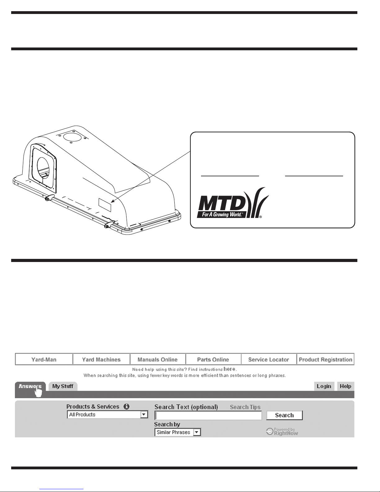
Finding and Recording Model Number
BEFORE YOU START ASSEMBLING YOUR NEW EQUIPMENT, please locate the model plate and copy the information from
it in this Operator’s Manual for future reference. The information on the model plate is very important if you need help from our
Customer Support Department or your authorized dealer.
You can locate it by looking on the front, left portion of the plastic grass catcher cover as seen below:
Model Number Serial Number
*Locate the model plate on your bagger and copy the information from it in the space provided above for future reference.
Customer Support
Please do
purchased, without first contacting Customer Support.
If you have difficulty assembling this product or have any questions regarding the controls, operation, or maintenance of this unit,
you can seek help from the experts. Choose from the options below:
• Visit www.mtdproducts.com for many useful suggestions. Click on the Customer Service link and you will get several
options to help in answering your questions. Click on the appropriate button and help is immediately available.
NOT
return the unit to the retailer from which it was
• If you prefer to reach a Customer Support Representative, please call
2
1-800-800-7310.
To The Owner
NOTE: Model 190 Triple Bagger Kit is designed for use
on Fast Attach™ compatible tractors equipped with 50inch cutting deck only. This will NOT mount, nor operate
safely or properly on any other tractor regardless of the
tractor’s compatibility with similar accessories.
The instructions in this manual are divided into sections
that cover the installation of the 190-190-100 & 190-192190 on a 50” deck. Carefully read all sections and study
the illustrations to ensure proper installation and usage
of this attachment. Read and observe all WARNING and
CAUTION statements. They are included to provide for
the protection of the equipment installer and user, and to
ensure the prolonged service life of the equipment.
NOTE: References to LEFT and RIGHT indicate the left
and right sides of the tractor when facing forward in the
operator’s position. Reference to the FRONT indicates
the grille end; to the REAR, the rear end of the tractor.
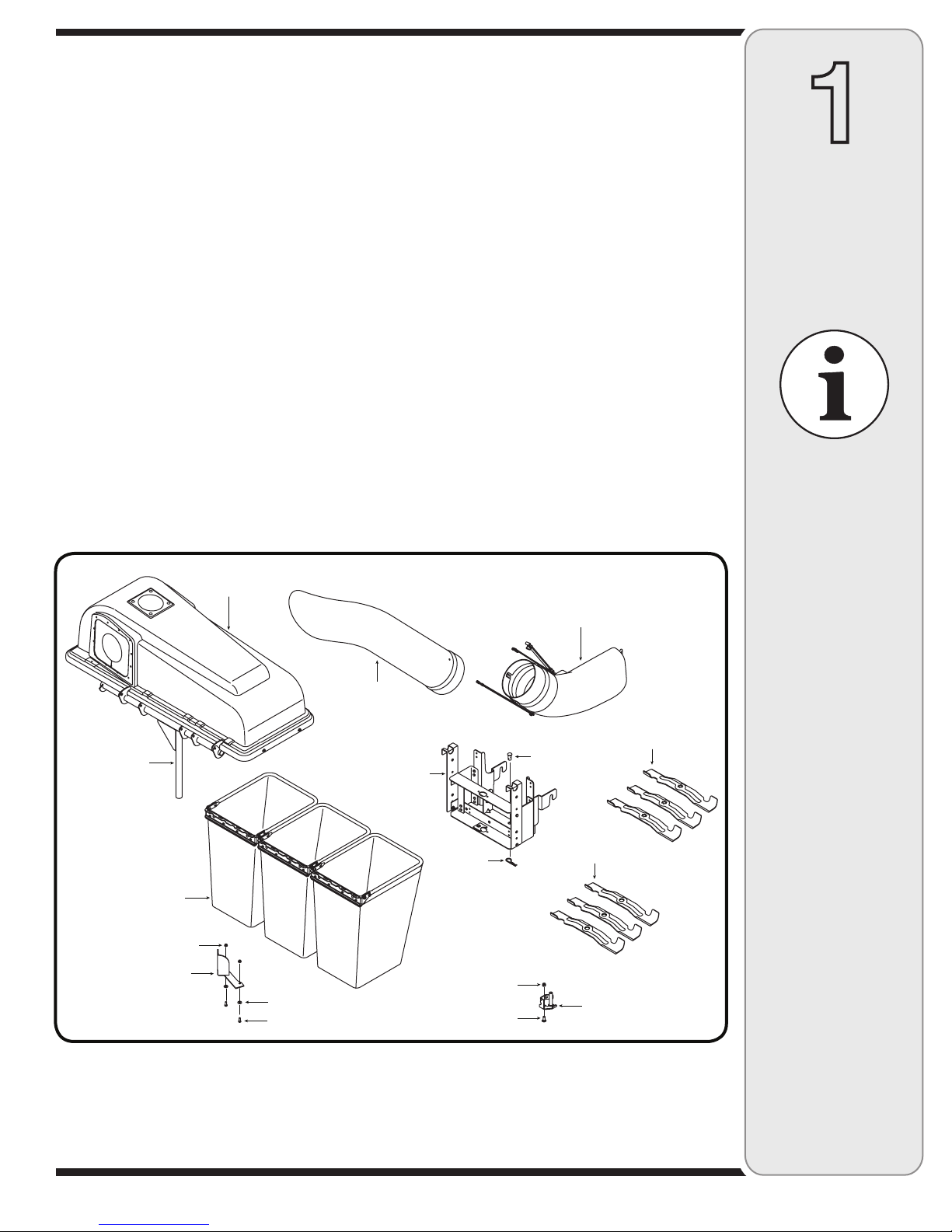
CONTENTS OF CARTON
Before beginning installation, remove all parts from the carton to make sure everything is present. Carton
contents are listed below and shown in Fig. 1-1.
One Chute Tube
One Discharge Chute Assembly
Three Grass Bag Assemblies
One Support Tube
One Grass Catcher Cover Assembly
One Mounting Bracket
(Shown Assembled)
Cover
Assembly
Three Blades (Star Hole Center)
Three Blades(Round Hole Center)†
Tube Extension
Chute Stop Bracket
Deck Deflector
† Included with Model 190-190-100 & OCC-190-192.
Discharge Chute
Assembly
1
To The Owner
&
Contents of
Carton
For parts and/or
accessories
please call
1-800-800-7310, or
1-330-220-4683.
www.mtdproducts.com
Support Tube
(attached to cover
assembly)
Grass Bag
Assemblies
Flange Lock Nut
Deck Baffle
Bell Washer
HH Cap Screw
Chute Tube
Bracket
Assembly
Figure 1-1
Hairpin
Clip
Hex Lock Nut
Carriage Bolt
Clevis Pin
Blades
Blades
†
Chute Stop Bracket
3
2
Assembly
And
Operation
NOTE:
References to left,
right, front and rear
of the tractor are
from the operator’s
position, unless
otherwise stated.
IMPORTANT:
There are two holes in
the clevis pin. Be sure
to insert the hairpin
clip in the upper hole
to properly secure the
bracket assembly to
the hitch plate.
Assembly & Operation
NOTE: References to left, right, front and rear of the
tractor are from the operator’s position, unless otherwise
stated.
• Before assembly, place the tractor on a firm, level
surface, disengage the PTO, stop the tractor engine
and set the parking brake.
• For convenience, pivot the seat forward and leave
it in that position until the grass collector is fully
mounted and assembled.
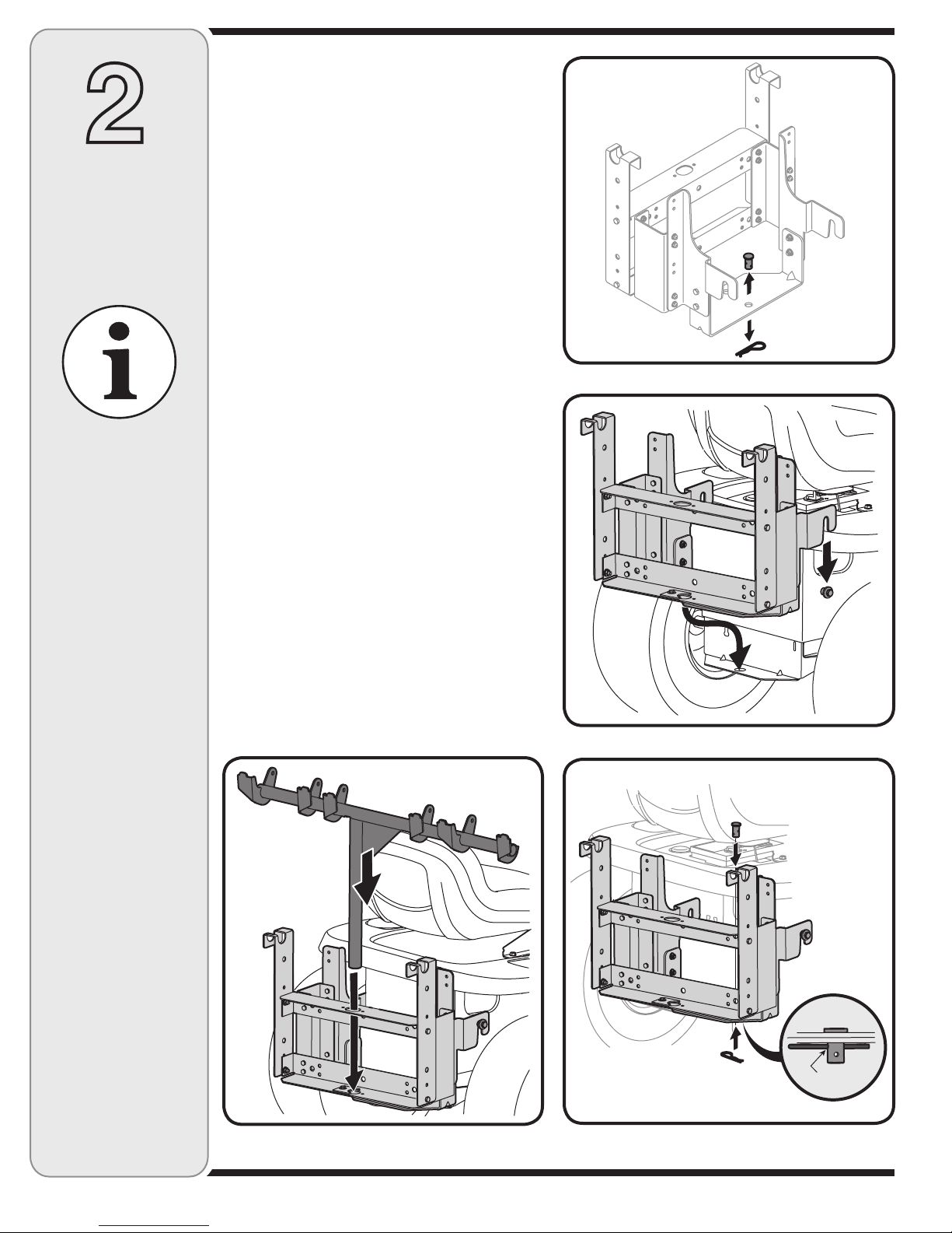
Mounting Bracket Assembly
• Remove the hairpin clip and clevis pin from the rear
of the mounting bracket assembly. See Figure 2-1.
• Position the hooked ends of the bracket assembly to
the outside of the hitch plate and over the shoulder
bolts. See Figure 2-2.
• Reinsert the clevis pin through the aligned holes
in both the bracket assembly and the hitch plate.
Secure with the hairpin clip. See Figure 2-3.
IMPORTANT: There are two holes in the clevis pin.
Be sure to insert the hairpin clip in the upper hole to
properly secure the bracket assembly to the hitch plate.
Attaching Grass Catcher Cover
and Grass Bags
• Place the grass catcher cover assembly’s support
tube in position on the rear of unit by sliding the
support tube down through the center hole in the
mounting bracket assembly. See Figure 2-4.
• Lift the grass catcher cover and attach the grass
bags using the slots shown in Figure 2-5. Close the
grass catcher cover.
NOTE: Cover not shown for clarity.
Figure 2-1
Figure 2-2
Figure 2-4
upper hole
Figure 2-3
4
 Loading...