

Page 1

10 CENTS
...g:. ... -Ty
Model Nos. 190-768
F
191-768
37
For one year from date of purchase, MTD Products !nc ,
will replace for the original purchaser, free of charge, F.O.B.
factory or authorized service firm, any part or parts found to
be defective in material or workmanship. All transportation
charges on parts submitted for replacement under this war
ranty must be paid by the purchaser. This warranty does not
include replacement of parts which become inoperative
through misuse, excessive use, accident, neglect, improper
maintenance or alterations by unauthorized persons. This
warranty does not include the engine, motor, battery, bat
tery charger or any component parts thereof. For service on
these units refer to the applicable manufacturer's warranty.
The above warranty will apply only to the original owner
and will be effective only if the warranty card has been pro
perly processed. It will not apply where the unit has been
used commercially.
Warranty service is available through your local author
ized service dealer or distributor. UNDER NO CIRCUM
STANCES WILL THE RETURN OF A COMPLETE UNIT
BE ACCEPTED BY THE FACTORY UNLESS PRIOR
WRITTEN PERMISSION HAS BEEN EXTENDED.
36” SNOW THROWER
TT^
1. Know the controls and how to stop quickly—READ
THE OWNER'S MANUAL.
2. Disengage power and stop motor before cleaning dis
charge, removing obstacles, making adjustments, or
when leaving operation position.
3. Never direct discharge at bystanders nor allow anyone
in front of machine—debris may be hidden in the snow.
4. Keep children and pets a safe distance away.
5. Do not allow children to operate machine nor allow
adults to operate It without proper instruction.
6. Adjust height to clear gravel or crushed rock surface.
7. Exercise caution to avoid slipping or falling, especially
when operating in reverse.
8. Handle gasoline with care — it is highly flammable.
A. Use approved gasoline container.
B. Never add gasoline to a running motor — fill tank
out of doors and wipe up spilled gasoline.
C. Replace gasoline cap securely.
D. Open door if motor is run in garage — exhaust
gases are dangerous.
9. Disengage ail clutches and shift into neutral before
starting motor. Keep hands, feet and clothing away
from power driven parts.
10. Use a grounded three wire extension cord for all plug
in electric units.
11. Keep machine in good operating condition and keep
safety devices in place.
MTD FRODDCTS IlSTC • 5389 WEST 130th ST. • P.O BOX 2741 • CLEVELAND, OHIO 44111
FORM NO. 770-2862A
Page 2
ASSEMBLY INSTRUCTIONS FOR MODEL 190-768 AND 191-768 SNOW BLOWER
1. Remove bag of parts, elbow assembly and
control rods.
2. Remove cardboard inserts.
3. Remove snow thrower. Be sure that every
thing is out of the carton before discarding
the carton.
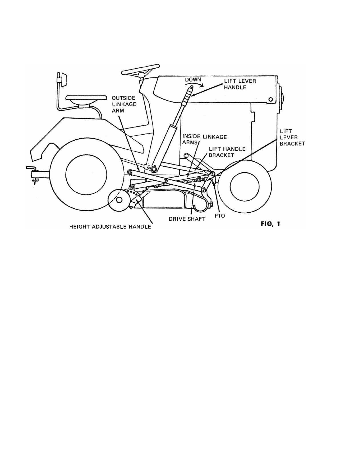
4. Remove cutting unit from tractor.
A. Remove cotter pin and outside linkage
arm from tractor.
B. Remove cotter pin and Inside linkage
arm from tractor.
C. Remove cotter pin and Lift lever bracket
from tractor.
D. Disconnect Drive shaft at the P.T.O.
and remove.
E. Slide cutting unit out.
5. Remove front hanger bracket from snow
thrower by removing the clevis pin and
cotter hairpin.
6. Attach hanger bracket to tractor with four 5/16
bolts and sems nuts provided. See Fig. 3.
7. Attach snow thrower to mounting brackets
with clevis pins and cotter hairpin. See Fig. 2.
8. Remove battery ground wire from Left Hand
side plate. Attach clutch support bracket to
side plate and replace battery ground wire
and bolt.
9. Attach clutch rod to clutch engagement lever
with 5/16 X 7/8 bolt.
10. Attach stack control rod In eye bolt. Attach
clip to control rod and attach clip to clutch
support bracket with clevis pin and cotter
hairpin.
Page 3
•n
.5
K>
GUIDE
CRANK
CLUTCH SUPPORT
BRACKET
•
1
1
•
1 ;
1 \ \
1
,
1
co
LIFT ROD,
j
1 L
CLUTCH ROD
BATTERY GROUND
WIRE
\ l
PIVOT BAR
SPRING LIFT BALANCE
SNOW THROWER
FRAME
CLEVIS PIN
COTTER HAIR PIN
Page 4

Page 5

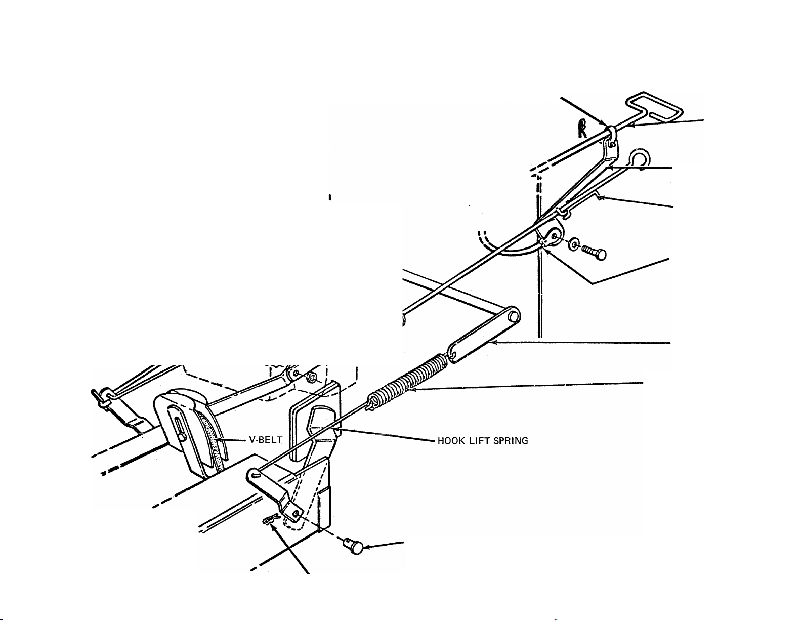
11. Remove clevis pin from lift bar. Attach wire
hook to one end of each spring. Attach wire
hook end of spring on the snow thrower arm
with hole and the other end of spring on the
lift bar.
12. Remove lift hitch rod from lift handle. Insert
oblong spacer between lift handle and hitch
lift rod. Attach with clevis pin and cotter
hairpin. (Clevis pin provided is longer than
the one on the tractor.)
13. Attach lift rod to snow thrower and oblong
spacer. Use cotter hairpin to attach lift rod
to spacer.
14. Attach belt keeper on inside of grille with
large flat washer, lockwasherand bolt provided.
DO NOT TIGHTEN. Be sure belt keeper is in
such a position that it will not allow the belt
to come off the pulley.
15. Be sure the snow thrower is disengaged. At
tach belt to front P.T.O. sheave. Tighten
belt keeper.
16. Attach elbow assembly to stack control. Hook
loop end of cable over the stud on the elbow.
WHEN ORDERING REPLACEMENT PARTS, PLEASE ORDER FROM:
HABAN MANUFACTURING COMPANY
MOUND AND MARQUETTE STREET
RACINE, WISCONSIN 53404
Page 6

co
Page 7

PARTS LIST FOR 36" SNOW THROWER MODEL NOS. 190-768 AND 191-768
Ulus.
No.
2
3
4
5
6
7
8
9
10
11
12
13 GM-9413534
14
Part
No.
6462
3013
GM-126203
GM-271178
3045
GM-126216
Assembly — Header Hsg. (AW)
Blade — Scraper
Bolt — Blade to Header 1/4—20 x 5/8 Carr.
Nut & Lock Washer Ass’y-Blade to Header (1/4—20 Hex)
Shoe — Skid
Bolt — Shoe to Header (5/16—18x3/4) Carr.
Description
GM-271184 Nut & Lock Washer Ass’y- — Shoe to Header (5/16—18 Hex)
6336
6338
Assembly — Stack Drive Brkt. (AW)
Assembly — Tube & Cable (Complete)
3955 Eye Bolt — Drive Tube
GM-120388
Washer - Eye Bolt (3/8 Flat) 7/16 x 1 x .083
Nut — Eye Bolt (3/8—16 Hex Lock)
GM-120915
Bolt — Brkt. to Header 3/8—16 x 1 Carr. 44
Ulus.
No.
32
33
38
39
40
41
42
43
15 4506 Washer — Brkt. to Header (3/8 Flat) 13/32 x 1-1/2 x .0598 45
16
GM-271190 Nut & Lock Washer Ass’y- — Brkt. to Header 3/8—16 Hex
3014 Assembly — Auger (36” AW) 47
17
5474 Bearing — Auger 48
18
5473
19
20 GM-180075
21 GM-120214
22 3022
Flangette — Bearing
Bolt — Auger Bearing (5/16—18 x 5/8 Hex Head)
Washer — Auger Bearing (5/16 Med. Lock)
Assembly — Auger Shaft (36”) AW
46
49
23 GM-180075 Bolt — Shaft to Header (5/16—18 x 5/8 Hex Head)
24
GM120214
Washer — Shaft to Header (5/16 Med. Lock)
25 GM-180175 Bolt - Shaft to Header (1/2-13 x 1-1/4 Hex Head)
26
GM-138549
3916 Spacer— Auger Shaft (End Opposite Sprocket)
27
28 4143 Washer — Auger Shaft (1-1/32 x 1-1/2 x 1/8 Flat)
4143
29
30 3026 Sprocket — Auger Driven (35 Tooth)
31
3027
Washer — Shaft to Head (1/2 Shake-proof Lock)
Between Brg. & welded Washer
Washer — Augher Shaft (1-1/32 x 1-1/2 x 1/8 Flat)
(End Opposite Sprocket for Spacing)
Spacer — Sprocket
54
55
56 6550
57
58
59 5028
60
Part
No. Description
34
35
36
37
GM-180087
GM-120214
6474
3036
GM-9414012
6476
Bolt — Sprocket to Auger (5/16—18 x 2 Hex Head)
Washer — Sprocket to Auger (5/16 Med. Lock)
Chain — Auger Drive 68 Links (Conn. Endless)
Guard — Chain (Galvanized)
Screw- Chain Guard (1/4 x 1/2 Hex Washer) Head Self Tap
Assembly — Jachshaft Housing & Bushings (Complete)
3034 Bushing — Jackshaft
50
51
52
53
5074
GM-120389
GM-120238
6479
3396
S-271
6481
GM-142671
6484
GM-120382
GM-180120
GM-271190
6485
GM-120386
4119
GM-126177
6547
Fitting - Grease (1/4-28 Self Tap. Str.)
Washer — Jackshaft Hsg. to Supports (1/2 x l-l/4x .083 Flat)
Nut - Jackshaft Hsg. to Supports (1/2—13 Half Hex)
Assembly — Jackshaft & Sprocket (AW)
Washer - Drive Pulley Spacer (3/4 Flat) 49/64 x 1-1/2-x 16 Ga.
Key - Drive Pulley Locking §9 Woodruff
Assembly — Sprocket & Hub (AW)
Screw - Set (Sprocket & Hub) 5/16-18 x 1/2 Sq. Head CupPt.
Bracket — Jackshaft Mounting
Washer — Jackshaft Mtg. Brkt. to Header Channel
Bolt — Jackshaft Mtg. Brkt. to Header Channel
Nut & Lock Washer Assembly — Jackshaft Mtg. Brkt. to
Retainer — Belt (Rear)
Washer — Retainer to Header Channel (1/4 Flat) 5/16 x 3/4 x .065
Nut — Retainer to Header Channel 1 /4—20 Hex Lock
Nut — Retainer to Header Channel 1/4—20 Wing
Assembly — Jackshaft Mounting Brkt. (AW)
Assembly — Jackshaft (Complete) (AW)
5429
5030
Washer — (J’shaft to Brg.) (1-1/16 x 49/64 x .1196)
Assembly — Bearing & Flange
Flange — Bearing
4611
Bearing
(3/8 Med. Lock)
(3/8-16 X 3/4 Hex Head)
Header Channel (3/8—16 Hex)
Page 8

PARTS LIST FOR 36” SNOW THROWER MODEL NOS. 190-768 AND 191-768 (Continued)
illus.
No.
Part
No.
Description
IHus.
No.
Part
No.
Description 1
1
j
61 GM180120 Bolt - (J’shaft to Brg.) 3/8-16 x 3/4 Hex Head
62
63
64
GM-120388
GM-120382
GM-180120
Washer — (J’shaft to Brg.) 3/8 Med. Flat (7/16 x 1 x .083)
Washer — (J’shaft to Brg.) (3/8 Med. Lock)
Bolt — (Flange to J’shaft Brkt.) 3/8—16 x 3/4 Hex Head 97 4119
65 GM-9413534 Nut — (Flange to J’shaft Brkt.) 3/8—16 Hex Lock
66
6490 Assembly — Idler Arm (AW)
67 6488 Assembly — Idler Pulley (4-1/2 O.D. A Sec.)
68
69
6495
GM-126509
Shield — ^lley
Bolt — (Pulley & Shields to Arm) 1/2—13 x 2-1/4 Carr.
70 GM-9417098 Washer — (Pulley & Shields to Arm 1/2 Flat) (17/32 x 1 x .063)
71
GM-138549
Washer — (Pulley & Shields to Arm) 1/2 Shakeproof Lock
72 GM-120378 Nut — (Pulley & Shields to Arm) 1/2—13 Lt. Hx.
73
6496
74
5759 Spacer — (Idler Brkt. To J’shaft Bracket)
Strap — Clutch Rod Mounting
75 GM-180134 Bolt — (Idler Brkt. Spacer, J’shaft Bracket, Flange)
00
GM-9413534
76
6553
77
3554
78
6488 Assembly — Idler Pulley (4-1/2 O.D. A Sec.)
79
Nut — (Idler Brkt. Spacer, J’shaft Brkt. Flange) 3/8—16 Hex Lock
Assembly — Idler Bracket (AW)
Spacer — Idler Bracket
3/8—16 X 2-1/2 Hex Head
80 GM-180192 Bolt -(Spacer & Pulley to Brkt.) 1/2-13x3-1/2 Hex Head
81
GM-138549 Washer — (Spacer & Pulley to Brkt.) 1 /2 Shakeproof Lock
82 6556
83 GM-180122
GM-120388
84
GM-271190
85
Chain — (Shaft to Rear Drive Brkt.) 46 Conn. Endless
Bolt — (Mtg. Brkt.) to Header Channel) 3/8—16 x 1” Hex Head
Washer — (Mtg. Brkt. to Header Channel) 3/8 Flat (7/16 x 1 x .083)
Nut & Lock Washer Ass’y. — (Mtg. Brkt. to Header Channel)
3/8-16 Hex
6498 Belt — Retainer
86
3090 Pin — Hair Cotter
87
4957 Assembly — Deflector & Elbow (AW)
88
5074 Fitting — Grease 1/4—28 Str. Self Tap
89
GM-180016 Bolt — Cable 1/4—20 x 1/2 Hex Head
90
GM-120386
91
3052
92
6558
93
GM-180020 Bolt — Deflector to Elbow 1/4—20 x 3/4 Hex Head
94
Washer — Cable 1/4 Flat 5/16 x 3/4 x .065 125
Deflector Elbow
Molding — Deflector (See Note)
95 3903
96 4506
98 3095
3095
99
6493 Assembly — MTG. Frame (AW)
100
101 GM-180079
GM-446363
102
103 GM-271184
104
3980
3341 Pin — Hair Cotter (Frame to Header) Assembly to Header
105
106
6502
3434
107
108 6503 Rod — lift
6504
110
111
6505
6506 Assembly — Rod Support Bracket (AW)
112
113 6508 Rod — Crank
114
6521
115 3694
116 3090
117
6509
4743 Ext. Clutch Rod (Assembly to Rod)
118
119 3090
120 GM-180077
121 GM-9413447 Nut — Ext. to Clutch Rod Mtg. Strap 5/16—18 Hex Lock
122 6511
123
6512 Assembly — Belt Popper (AW) (Engine)
124
GM-180130 Bolt — Belt Popper to Tractor Grill 3/8—16 x 1-3/4 Hex Head
GM-120382 Washer — Belt Popper to Tractor Grill 3/8 Med. Lock
126
6515
Washer — Deflector to Elbow 3/8 x 7/8 Concave Tooth
Washer — Deflector to Elbow 3/8 Flat Special
(13/32 X 1-1/2 X 16 Ga.)
Nut — Deflector to Elbow 1/4—20 Hex Lock
Clip — Connector Link
Link — Connector
Bolt — (Mtg. Frame to Tractor) 5/16—18x1 Hex Head
Washer — (Mtg. Frame to Tractor) 5/16 Flat 3/8 x 7/8 x .083
Nut & Lock Washer Ass’y. — Mtg. Frame to Tractor
5/16-18 Hex
Pin — Clevis ( Frame to Header) Assembly to Header
Hook — lift Spring
Spring — Lift Balance
Extension — lift Lever
Pin — Clevis (Ext. to Tractor — Lift Lever
(MTD with Hardware on Tractor)
Guide — Crank Rod
Pin — Clevis (Guide to Support Bracket)
Pin — Hair Cotter (Guide to Support Bracket)
Assembly — Clutch Rod (SW)
Pin — Hair Cotter (Ext. to Rod)
Bolt — Ext. to Clutch Rod Mtg. Strap 5/16—18 x 3/4 Hex Head
V-Belt — (Main Drive) A-66 68.3 — O.C. (Ass’y. on Header)
Washer — Belt Popper to Tractor Grill 3/8 Special Flat
(13/32x2-3/8x3/16)
 Loading...