

Page 1
'Ш
FORM NO. TLP-009
OPERATING INSTRUCTIONS AND SERVICE MANUAL
8 H. P. ROTARY TILLER
MODEL 1850
2 //- 3?o
Original: February 1971
J. G. РЕШУ GGNPm, MG.-I30i AVENE OF THE ШВОШ, HEW YHRE, &T., IHII
Page 2

CONTENTS
Section Paragraph
GENERAL INFORMATION AND ASSEMBLY
1.
1-1. Technical Description
1-2. Preliminary Preparation ....................................... 1-1
1- 3. Assembly ...................................................... 1-1
CONTROLS AND PRELIMINARY CHECKS
2.
2- 1. Controls .............................................................. 2-1
2-2. Wheel Adjustment
2-3. Checking Oik Gasoline, and Gear case... 2-2
OPERATING INSTRUCTIONS
3-1. Starting the Engine _________
3-2.
Stopping the Engine __________
3-3.
Stopping the Tines
..........................................
........
....................................
_____
-
.............
___
_
—
_______________
_________
-----
Page Section Paragraph
1-1
--2-2
—- 3-1
-------
3-1
3-1
MAINTENANCE
4-1.
Crankcase Oil
4-2.
Chain Case Lubricaion
4-3.
Chain Adjustment
4-4.
Air Filter
4-5.
Cleaning Engine and Tine Area
4-6.
Belts .................................................
4-7.
Spark Plug
4-8.
Gasoline Filter and Shut-OfF Valve
4-9,
Belt Adjustment
4-10.
Belt Replacement
4-11.
Adjusting the Carburetor
4-12.
Adjusting the Choke
4-13.
Magneto and Spark Plug Check
4-14.
Off-Season Storage
.......
..........
....................................
___________
..............
................
.........
........
..............................
__________
.............................
..............................
......................
.............
..................
_______
EXPLODED VIEWS AND PARTS LIST
................
___________
.......
.................
................
___________
______
____
........
Page
.....
4-1
.. .. 4-1
.... 4-1
.... 4-1
.... 4-2
.... 4-2
.... 4-2
.... 4-2
.... 4-3
... 4-3
.... 4-4
.... 4-4
.... 4-5
.... 4-5
5-1
Figure
Wheel Assembly
1-1.
Wheel Flanger ------------
1-2.
Handle Assembly
1-3.
Control Assembly
1-4.
Ferrule Adjustment
1-5.
Control Assembly
1-6.
Throttle Assembly
1-7.
2-1.
Controls
Depth Bar
2-2.
Wheel Height Adjustment
2-3.
Oil and Gasoline Fill ............
2-4.
3-1. Recoil Starter
Oil Fill Plug
4-1.
4-2. Oil Drain
________
.............................................
__________
..................
.........
...........
—..........—
-------------
........
....................
..............—--------
--------
--------
-------
-----------------------
------
----------
-------------
__________
--------------------
...................
.....
.....................................
_____________
...........
...................
-----
—.
.......
-------
-----------
______
ILLUSTRATIONS
Page Figi
...... 1-2
____
1-2
____ 1-2
____
1-2
......
1-3
____
1-3
_____
1-3
____
2-1
..........
2-1
-
.......... 2-2
_____
2-2
..........
3-1
_____
4-1
_____
4-1
ure Page
Air Cleaner
4-3.
Spark Plug
4-4.
Gasoline Filter and Shut-Off .........
4-5.
Drive System
4-6.
4-7. Variable Speed Pulley ...............................
Belt Removal
4-8.
Carburetor Adjustment ..................
4-9.
Choke Adjustment
4-10.
Penncraft Tiller Model 1850
5-1.
Penncraft Tiller Model 1850
5-2.
Engine Model 190402-0689-01 ...
5-3.
____________
...................................
----------------------------
-------------------------------------
.........
..........................
___________
.............
..................
.....................
---------
............
.......
_
........
____
........
____
......... 4-3
........
____
.
____
.
.........
.
____
4-1
4-2
4-3
4-3
4-3
4-4
4-5
5-2
5-3
5-5
Page 3

SAFETY RULES
BEFORE TILLING
1. DO NOT operate the equipment when barefooted
Of when wearing open sandals.
2. DO NOT start machine until each control and its
function is understood. See Sections 2 and 3.
3. DO NOT let anyone use the tiller who is unfamiliar
with the controls. Keep children and pets away
from the machine.
4. Check tank for fuel of crankcase for oil level. See
Section 2.
5. Always disconnect the sparkplug wire during re
pairs, refueling, or adjustments except when tun
ing the engine.
6. NEVER refuel with motor running.
7. DO NOT spill gasoline on hot engine.
8. NEVER try to start the engine with the clutch con
trol in any position but NEUTRAL.
9. Stand clear of tines when starting the engine.
10. Never stand in front of or work on tines when the
engine is running. Keep hands and feet clear of
tines.
AFTER TILLING
1. Read and understand all instructions in Sections 2
and 3.
2. NEVER use the tiller in the dark.
3. STOP the engine and remove the spark plug wire
whenever the machine is left unattended.
4. Never leave an operating tiller unattended.
5. If the machine begins to vibrate or produces any
other than normal operating sounds, STOP the
machine immediately and check the cause.
6. Keep children away from the operating tiller at all
times.
7. Know how to stop the tiller instantly.
8. Stop the machine when crossing driveways, roads,
or walkways.
9. If the blades strike any obstructions, STOP the en
gine, remove the spark plug wire, and check for
damage.
Page 4
SECTION I
GENERAL INFORMATION AND ASSEMBLY
1-1. TECHNICAL DESCRIPTION
The Model 1850 Rotary Tiller is equipped wih a
Briggs and Stratton 8 hp, 4-cycle engine and a recoil
starter. The tines are heavy duty slasher type and the
wheels are 10 x 2.50 inches with a rib tread. This til
ler weighs 340 pounds.
The maximum tilling width is 26 inches.
1-2. Preliminary Preparation
Maximum tilling results, equipment performance,
and personal safety depend on correct operation of
the equipment and on proper maintenance of its com
ponents. The operator of this Penncraft rotary tiller
should, therefore, famiarize himself with the machine
and its controls before attempting to operate the
equipment. The two important considerations are:
a. Knowing the location of each control and its
function, as outlined in this manual, to ensure
for most efficient operation of the equipment and
for best performance.
b. Observing the operating instructions and safety
rules at all times to prevent possible injury to
persons and to equipment.
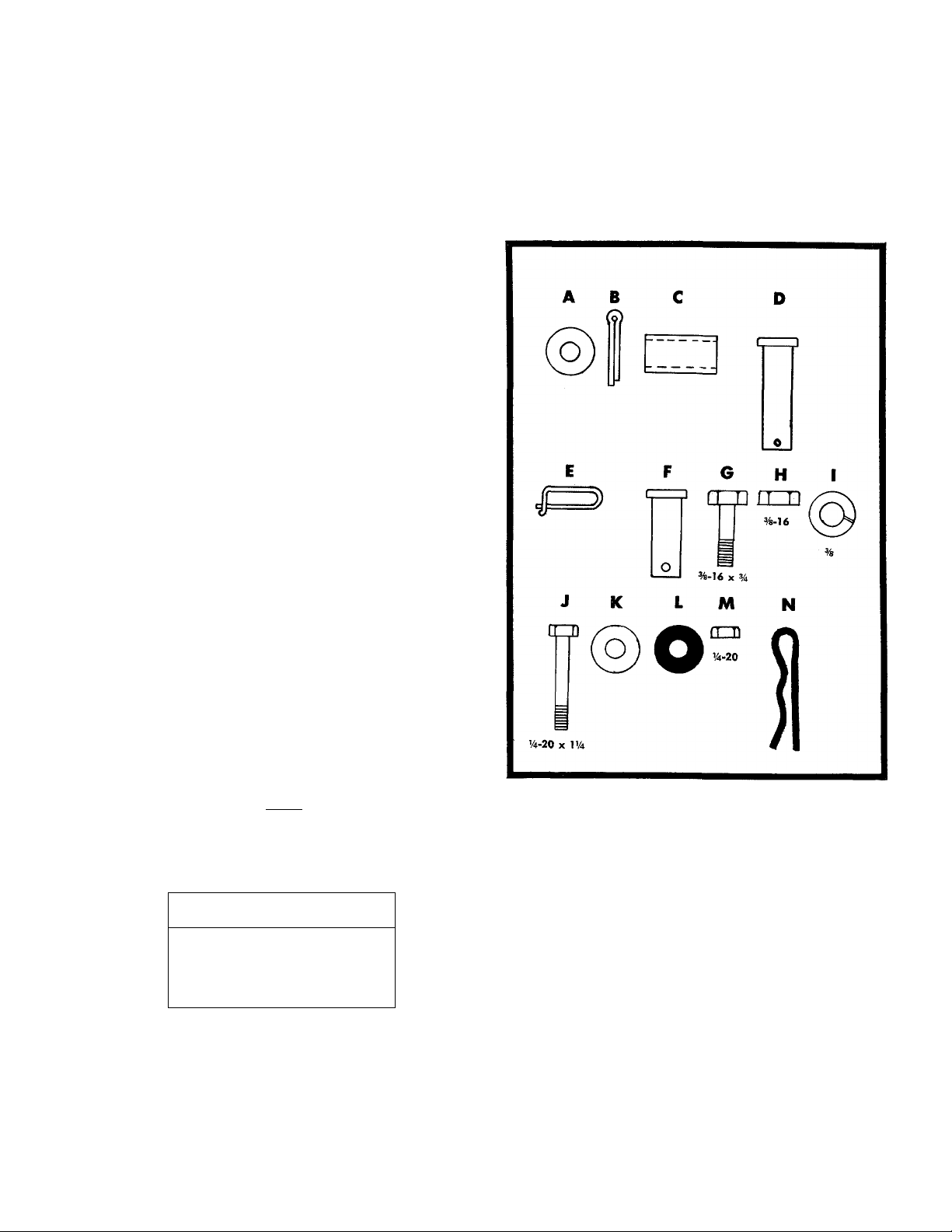
HARDWARE SUPPLIED
1-3. Assembly
The Model 1850 is shipped completely assembleo
except for the handle, depth bar, and wheels. These
parts, with the necessary hardware, are easily assem
bled to the machine, as outlined in this section.
NOTE
Reference to right-hand or left-hand
side of machine is from the operating
position.
TOOLS NEEDED
Two 7/16"
Two 9/16" Wrenches
Wrenches
a. ' heel and Wheel Hanger Assembly
Refer to figure 1-1.
Step 1. Slide the axle through the wheel hanger.
Step 2. Place the washer A, spacer C, wheel, and
washer A on each side of the axle and secure
each with a cotterpin B.
1-1
Page 5
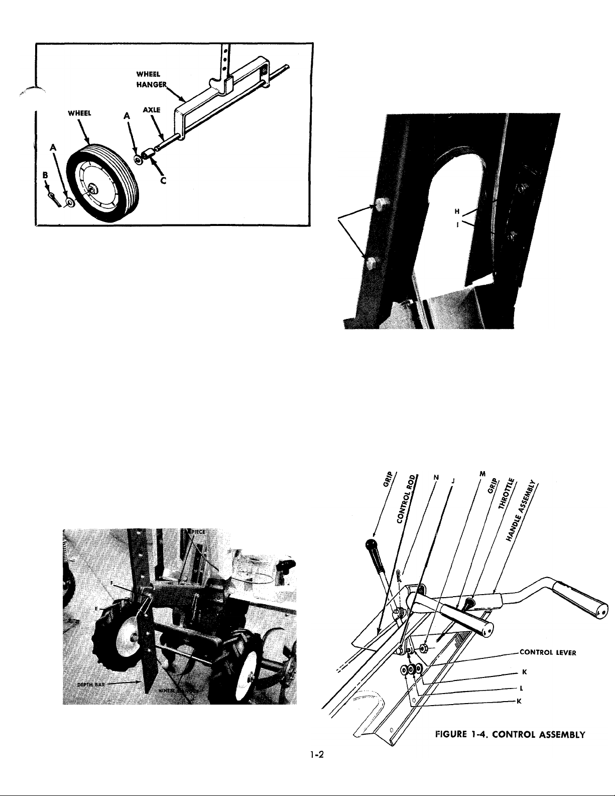
FIGURE 1-1. WHEEL ASSEMBLY
Refer to Figure 1-2.
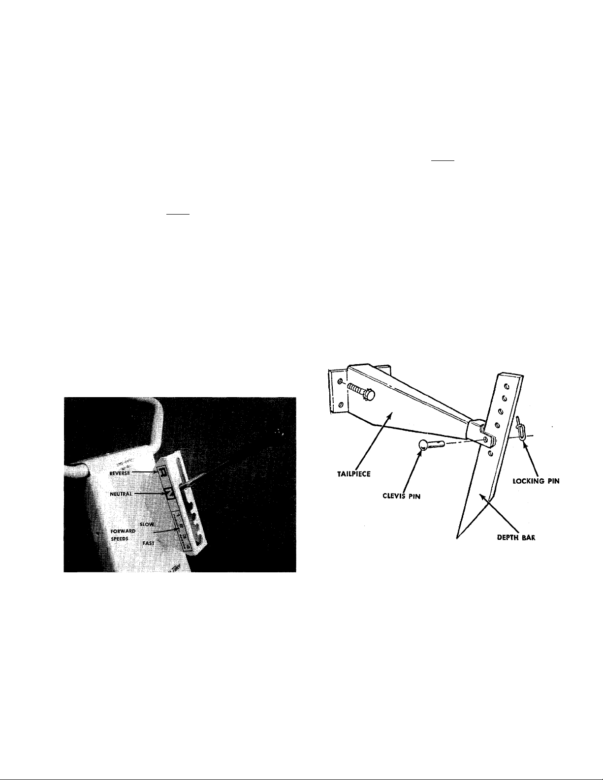
Step 3. Place the wheel hanger into the tailpiece and
secure with clevis pin D and locking pin E.
c. Handle Assembly
Refer to Figure 1-3.
Assemble the handle to the handle bracket with 4
hex bolts G, lockwashers I and hex nuts H.
b. Depth Bar
Refer to Figure 1-2.
Step 1. Attach the depth bar to the tailpiece with the
clevis pin.
Step 2. Secure the clevis pin F with the locking pin E.
FIGURE 1-3 HANDLE ASSEMBLY
d. Control Assembly
Refer to Figure 1-4.
Step 1. Place the control lever through the handle
assembly.
Step 2. Attach at the bottom with hex bolt J, steel
washer K, rubber washer L and secure with
hex nut M.
FIGURE 1-2. WHEEL HANGER AND DEPTH BAR
Page 6
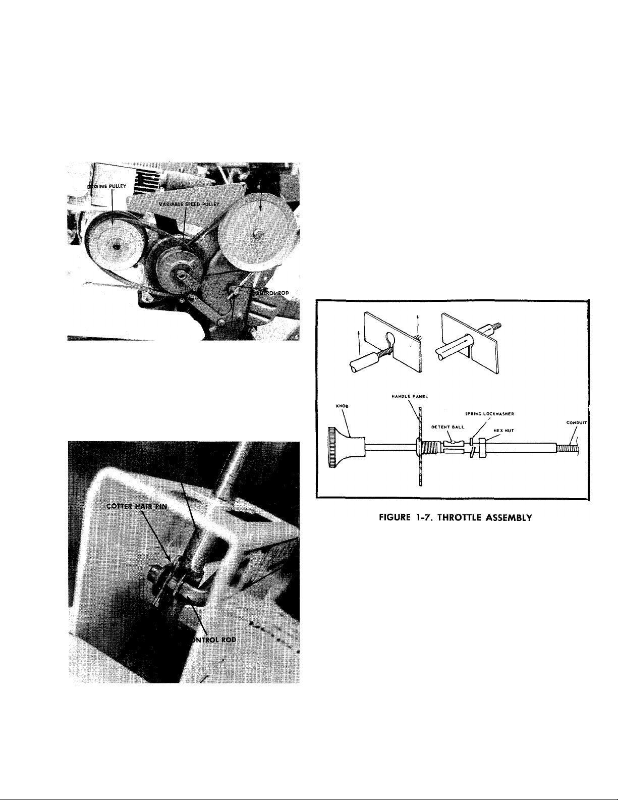
Refer to Figure 1-5.
Step 3. Screw the control rod into the ferrule until it
extends through the ferrule % of an inch.
e. Throttle Control Assembly
Step 1. Push the black plastic knob on the throttle
control all the way.
FIGURE 1-5. FERRULE ADJUSTMENT
Refer to Figure 1-6.
Step 4. Place the bent end of control rod into the
control lever and fasten with cotter hairpin N.
Step 2. Pull out the black knob until the detent
clicks twice to allow the spring lockwasher
and the hex nut to pass over the detent
boll to the threads.
Step 3. Slide the spring lockwasher and the hex nut
over the detent ball and thread the hex nut
one or two turns.
Step 4. Place the conduit through the slot in the
handle pandl.
Step 5. Push the throttle control in until it seats.
Step 6. Tighten the hex nut.
FIGURE 1-6. CONTROL ASSEMBLY
1-3
Page 7
SECTION 2
CONTROLS AND TRELIMINARY CHECKS
2-1. CONTROLS
The controls on Model 1850 Rotary Tiller are the
control lever and throttle control.
a. The Control Lever
The Control Lever is released from Neutral by mov
ing it to the right and allowing the spring tension to
pull the control lever into one ot the tour forward
speeds. See Figure 2-1.
NOTE
Number 1 position is the slowest tine
rotation speed and number 4 is the
fastest.
Pulling the control lever backwards into the Reverse
position reverses the direction of tine rotation.
b. The Throttle Control
The throttle control actuates the butterfly in the car
buretor and may be set at stop, slow, fast or choke to
control the speed of the engine.
NOTE
Always check the throttle cable at the
engine end for a tight connection.
To stop the engine, push the throttle control all the
way in. To operate the choke, pull the throttle control
all the way out. See Figure 2-1.
c. The Depth Bar
The depth bar is used to prevent the tiller from run
ning on top of the ground instead of tilling. The deep
er you set the depth bar, the deeper you will till. Tilling
depth is from 0 to 8-inc'hes. See Figure 2-2.
FIGURE 2-1. CONTROLS
FIGURE 2-2. DEPTH BAR
2-1
Page 8

2-2. WHEEL ADJUSTMENT
The wheel height can be adjusted by removing the
long clevis pin on the wheel hanger and raising or
lowering the setting. The higher the setting the deeper
the tilling depth. See Figure 2-3.
NOTE
Pick a height that places the handles in
b. Gasoline
Remove the gas cap and fill the tank with FRESH
REGULAR GASOLINE. If the gasoline has been in a
metal can for a long period, throw it away and use
fresh gasoline.
FIGURE 2-3. WHEEL HEIGHT ADJUSTMENT
2-3. CHECKING OIL, GASOLINE, AND GEAR CASE
NOTE
When packaged for shipment the ma
chine contains no oil or gasoline. Before
starting the engine, oil must be added
to the engine crankcase and gasoline
to the tank. DO NOT mix oil with gaso
line.
a. on
With the tiller on level ground, remove the oil filler
plug and pour 2% pints of good quality, SAE 30 type
MS engine oil into the crankcase. Replace the oil filler
plug.
The chain case is sealed and requires no further
lubrication unless the chain case is disassembled for
repair.
2-2
Page 9

SECTION 3
OPERATINC INSTRUCTIONS
3-1. STARTING THE ENGINE
Step 1. With the tiller set on level ground, set the
control lever in NEUTRAL.
Step 2. Set the throttle control to CHOKE.
Step 3. As illustrated in figure 3-1, grasp the recoil
starter handle, pull out sharply, and hold
it in the out position. (Do not let cord snap
back.)
3-2. STOPPING THE ENGINE
To stop the engine, push the throttle control all the
way in to the STOP position. See Figure 2-1. When the
throttle control is in the STOP position, a switch blade
is activated to short-circuit the spark plug.
WHENEVER THE TILLER IS LEFT UNAT
TENDED, DISCONNECT THE SPARK
PLUG LEAD AND PLACE THE THROHLE
CONTROL IN THE STOP POSITION.
3-3. STOPPING THE TINES
Pull the control lever into the NEUTRAL position. The
tines will not rotate. See Figure 2-1.
3-4. OPERATING THE TILLER
NOTE
The cord should NOT be pulled out
more than about two feet. If engine
fails to start, allow the cord to wind
back Into the housing, then pull out
sharply again. Refer to Step 5.
Step 4. When the engine starts, gradually move
the throttle to the FAST position. After en
gine warms up (about 2 or 3 minutes) set
throttle at IDLE position.
Step 5. DO NOT OVERCHOKE ENGINE. Repeated
cranking with throttle at CHOKE position
will cause gasoline to flood the intake tube
and the engine. If, after 3 or 4 attempts,
the engine fails to start, place throttle in
FAST position, crank the engine several
times to clear out the excess fuel; and then
proceed with steps 2, 3 and 4.
Typical operation of the tiller is as follows:
Step 1. Set the clutch control to NEUTRAL.
Step 2. Start the engine as outlined in paragraph
3-1.
NOTE
To move the tiller to- the work area,
keep the depth bar in the highest posi
tion. With the throttle in the SLOW posi
tion, slowly engage the control lever
into the number 1 position and the tiller
will walk to the work area without dig
ging into the ground.
Step 3. With the clutch control in NEUTRAL, set the
depth bar in one of the lower settings.
NOTE
When several passes must be made
over a certain area, lower the depth bar
each time a pass Is made.
3-1
Page 10

Step 4. Set the throttle control to FAST.
Step 5. Slowly engage the clutch control to the num
ber 1 position and the tines will begin rotat
ing, Number
mum tine speed. Tilling the ground for the
first time should be done in the number 1 or 2
position. To pulverize the soil after it has been
tilled, move the control lever to the number 3
or 4 position.
The engine must be running to move
the control lever into the faster speeds.
A downward pressure on the handles
will increase the working depth and re
duce the forward speed. An upward
pressure on the handles will reduce the
working depth and increase the for
ward speed. The type of soil and work
ing conditions will determine the actual
setting of the depth bar and the handle
pressure required.
4 position will give the maxi
NOTE
NOTE
CAUTION
If the tines stop rotating or the belt
slips, slop the engine and examine the
tine area for a rock or some object that
may be jamming the tines and prevent
them from turning. Reversing the tiller
Will usually free the object.
Step 6. To reverse the direction of rotation of the tines,
pull the control lever into the reverse position.
The control lever must be held in reverse. See
Figure 2-1.
1
3-2
Page 11

4-1. CRANKCASE OIL
SECTION 4
MAINTENANCE
To ensure maximum engine performance, perform
the following periodic maintenance:
a. Oil Check
Check the oil level in the crankcase before each use
of the machine and after every two hours of opration.
The oil level shall be over-flowing at the oil fill plug.
See figure 4-1.
OIL FILL PLUG
Step 1. With the machine on level ground, place a
suitable metal container under the oil drain
plug, then remove the drain plug.
Step 2. After the oil has been drained completely
from the crankcase, replace the drain plug
and tighten.
Step 3. Refill crankcase with 2% pints of SAE 30 en
gine oil (A.P.I. class MS). Pour the oil slowly
to eliminate airlock.
4-2. CHAIN CASE LUBRICATION
The chain is permanently lubricated and requires
no further lubrication unless the case is disassembled
for repair.
If the case is disassembled, clean the chain with
kerosene, allow it to dry and work a high temperature
grease, such as Lubriplate No. 310 into the chain.
NOTE
A 4 oz container of Lubriplate No. 310
is available under part number
727-136.
OIL DRAIN
FIGURE 4-1. OIL FILL PLUG
b. Oil Change
After the first two hours of operating a new engine,
drain the oil (see figure 4-2) from the crankcase while
engine is still hot and refill crankcase with new oil;
thereafter change the oil after every 25 hours of opera
tion. This procedure ensures for minimum wear of engin parts and provides for virtually trouble-free oper
ation. To change the oil, proceed as follows:
4-3. CHAIN ADJUSTMENT
No chain adjustment is necessary.
4-4. AIR FILTER
Under normal operating conditions, the air cleaner,
located on top of the carburetor, must be serviced
after every ten hours of use. Under extremely dusty
operating conditions, the air cleaner must be serviced
after every hour of operation. See Figure 4-3.
Step 1. Remove the wing nut and cover.
Step 2. Lift off foam element from support base.
Step 3. Remove metal support tube assembly (screen
and two metal caps) from foam element by
compressing the foam element.
4-1
Page 12

Step 4. a.Wash foam element in a solvent such as
kerosene or liquid detergent and wafer to
remove dirt.
b. Wrap foam in cloth and squeeze dry.
c. Saturate foam in engine oil, then squeeze
out excess oil.
NOTE
Belt tension is automatically main
tained on the forward and reverse drive
belts by idlers. No adjustment is neces
sary.
NOTE
Use the same oil for the air cleaner that
you use in the engine.
d. Assemble parts and fasten to the car
buretor.
FIGURE 4-3. AIR CLEANER
4-7. SPARK PLUG
The spark plug gap should be cleaned, and reset to
a 0.030-inch clearance every 25 hours of engine oper
ation (see figure 4-4). Spark plug replacement is rec
ommended at the start of each tiller season; check
engine parts list for correct plug type.
FIGURE 4-4. SPARK PLUG
4-5. CLEANING ENGINE AND TINE AREA
Any fuel or oil spilled on the tiller should be wiped
off promptly. Dirt, leaves and other debris must not be
left to accumulate around the cooling fins or the engine
or on any part of the tiller. Clean the under side of the
tine shield after each use. The dirt washs off the tine
easier if washed off immediately instead of after it
dries.
4-6. BELTS
Check that belts are free of oil or dirt. Wipe the belts
periodically with a clean rag.
4-8. GASOLINE FILTER AND SHUT-OFF VALVE.
Refer to Figure 4-5.
Step 1. Close the shut-off valve.
Step 2. Loosen the thumb screw below the bowl.
Step 3. Remove and clean the screen.
Step 4. Open the shut-off valve to see if gasoline
flows freely from the gasoline tank.
Step 5. Clean the bowl and screen. Use alcohol or
acetone to clean the parts if you find a gum
my, varnish-like substance in the bowl.
Step 6. Reassemble.
Step 7. Open the shut-off valve.
4-2
Page 13

FIGURE 4-5. GASOLINE FILTER AND SHUT-OFF
4-9. BELT ADJUSTMENT
To check the belt adjustment, it is necessary to re
move the belt cover so the belts are exposed as shown
in Figure 4-6.
BELT SHOULD BE IN THIS
POSITION WITH CONTROL
LEVER IN NO. 4 POSITION
VARIABLE SPEI
PULLEY
FIGURE 4-7. VARIABLE SPEED PULLEY
4-10. BELT REPLACEMENT
Step 1. Remove the belt cover so the belts are ex
posed as shown in Figure 4-6.
Step 2. Put the depth bar on the wheel hanger and
place the tip of the depth bar under the var
iable speed pulley bracket as shown in Figure
4-8.
FIGURE 4-6. DRIVE SYSTEM
Start the engine and move the control lever into the
number 4 position. The belt closest to the engine
should move to the outside edge of the variable speed
pulley so the top of the belt is almost flush with the
pulley. See Figure 4-7.
FIGURE 4-8. BELT REMOVAL
4-3
Page 14

Step 3. Place your foot on the rear of the depth bar
and apply pressure. The belts will go slack.
Step 4. Remove the REAR belt first and ALLOW IT TO
FORM A LOOP AROUND THE VARIABLE
SPEED PULLEY.
Step 5. Slide the center section of the variable-speed
pulley towards the engine. See Figure 4-7.
Step 6. Remove the FORWARD belt from the engine
pulley and the variable-speed pulley.
NOTE
By following this order of belt removal,
it is not necessary to remove the belt
guard on the varible-speed pulley.
Step 7. Remove the rear belt from the variable-speed
pulley.
Step 8. Reassemble with the new belts.
FIGURE 4-9. CARBURETOR ADJUSTMENT
4-n. ADJUSTING THE CARBURETOR
Minor carburetor adjustment may be required to
compensate for differences in fuel, temperature, alti
tude and load.
To Adjust Carburetor:
Turn needle valve clockwise until it just closes. See
Figure 4-9.
CAUTION
Valve may be damaged by turning it in
too far.
Now open needle valve IV2 turns counter-clockwise.
Close idle valve in same manner and open Va to %
turns. This initial adjustment will permit the engine to
be started and warmed up prior to final adjustment.
Final Adjustment;
Turn needle valve in until engine misses (lean mix
ture) then turn it out past smooth operating point until
engine runs unevenly (rich mixture). Now turn needle
valve to the mid-point between rich and lean so the en
gine runs smoothly.
Hold throttle at idle position and set idle speed ad
justing screw until fast idle is obtained (1750 RPM).
Hold throttle in idle position and turn idle valve in
(lean) and out (rich) until engine idles smoothly. Then
reset idle speed adjusting screw so that engine idles
at 1750 RPM. Release throttle—engine should accel
erate without hesitation or sputtering. If engine does
not accelerate properly, the carburetor should be re
adjusted to a slightly richer mixture.
4-12. ADJUSTING CARBURETOR CHOKE
Proper choke and stop switch operation is depend
ent upon proper adjustment of remote controls on the
powered equipment.
To Check The Operation Of The Choke:
Step 1. Remove the air cleaner.
Step 2. Pull the throttle control all the way out to the
CHOKE position. See Figure 2-1. The choke
should be closed.
Step 3. The engine should shut off when the throttle
control is all the way in. (STOP position.)
To Adjust;
Place remote control lever on equipment in FAST
(high speed) position. Loosen control casing clamp
screw "B." Move control casing "A" and wire until lever
"D" touches choke operating link at "C." Tighten cas
ing clamp screw "B." Replace air cleaner. See Figure
4-10.
4-4
Page 15

4-14. OFF-SEASON STORAGE
/■
If the machine is to be inoperative for a period long
er than 30 days, the following precautions are recom
mended;
Step 1. Working outdoors, drain all fuel from the
fuel tank. Use a clean dry cloth to absorb
the small amount of fuel remaining in the
tank, then run the engine until all fuel in
carburetor is exliausted.
|W\RNIN^
DO NOT DRAIN FUEL WHILE SMOKING
OR IF NEAR AN OPEN FIRE.
4-13. MAGNETO AND SPARK PLUG CHECK
WHENEVER CHECKING THE MAGNETO
OR THE SPARK PLUG FOR AN ELECTRI
CAL SPAR.K, USE INSULATED PLIERS TO
HOLD THE SPARK PLUG WIRE OR THE
SPARK PLUG,
a. Magneto Check
Step 1. Disconnect the spark plug wire from the
spark plug, and place throttle control lever in
CHOKE or FAST position.
Step 2. Drain all the oil from the crankcase (this
should be done after the engine has been
operated and is still warm) and refill the
crankcase with clean new oil.
Step 3. Disconnect the spark plug wire and remove
the spark plug from the cylinder. Pour
about six drops of engine oil into the cylin
der, and then pull the recoil starter several
times to spread the oil on the cylinder wall.
Replace the spark plug, but DO NOT con
nect the wire.
Step 4. Clean the engine and the entire tiller thor
oughly.
Step 5. Lubricate the gear cane an indicated in par
agraph 4-2.
Step 6. Wipe tines with oiled rag to prevent rust.
Step 2. Using insulated pliers, hold the wire close
('/4-inch distance) to engine block or cylin
der, then crank the engine several times. A
spark should jump from the wire to the
block or cylinder; if a spark does not occur,
check the wire and the magneto.
b. Spark Plug Check
Step 1. Remove spark plug from cylinder but leave
the wire connected, and set throttle at
CHOKE or FAST position.
Step 2. Using insulated pliers, hold the metal side
of the spark plug in contact with the engine
block, and crank the engine several times.
The spark should jump the gap between
the center and side electrode in the plug.
Step 3. If a spark does not occur, check the elec
trode gap and repeat step 2. If no spark
occurs, replace the plug.
4-5
Page 16

MAINTENANCE LOG
After using and servicing the machine, enter the data on this log for future reference. Change oil after
first 5 hours of operation; thereofter, change oil every 25 hours of operation. Clean the air cleaner every 10
hours; every hour under very dusty conditions. Lubricate all points indicated in figures 4-2, 4-3 and 4-4 every
10 hours.
STARTING
TIME
FINISHING
TIME
OPERATING
TIME
ACCUMULATED
TIME
OIL
CHANGE
AIR
CLEANER
LUBRI
CATION
COMMENTS
4-6
Page 17

SECTION 5
EXPLODED VIEWS
AND
PARTS LIST
5-1
Page 18

FIGURE 5-1. PENNCRAFT TILLER MODEL 1850
5-2
Page 19

FIGURE 5-2. PENNCRAFT TILLER MODEL 1850
5-3
Page 20

PARTS LIST—ROTARY TILLER MODEL 1850
WHEN ORDERING REPAIR PARTS, ALWAYS GIVE THE FOLLOWING INFORMATION AS SHOWN IN THIS LIST:
1. The PART NUMBER 2, The PART NAME 3. MODEL NUMBER
DO NOT use Reference Numbers when ordering Repair Parts, always use Part Numbers
Your lawn mower is right hand (R.H.) or- left hand (L.H,| as you ride.
REF.
PART
NO.
NO.
— Engine
1
2
710-380
384-4524
3
4 710-376 Hex Hd. Cap Scr. 5/16-18 x 1 Lg.*
6 710-216
7 720-143 Grip
714-507
8
9 711-422 Control Rod
10 710-106
712-107 Hex Center Lock Nut ’/4-20 Thd.*
11
12 305-1166
746-122 Throttle Control—Complete
13
14 384-4533
310-4525 Control Lever Assembly
15
736-325 Flat Washer^ .20
16
17 736-155 Rubber Washer
736-325 Flat Washer*
18
736-217
19
20 712-798 Hex Nut %-16 Thd.* .20
21 428-4506
22
710-253
23 736-217
428-4505 Handle Mounting Bracket R.H.
24
428-4507 Tail Piece
25
732-194 Spring Pin
26
27
736-148 Ext. Lockwasher for % Scr."^ .20
710-253
28
DESCRIPTION
Hex Hd, Cap Scr, 5 /16-18 x Lg/‘
Tine Shield
Hex Hd. Cap Scr. .20
Cotter Pin 3/32 x% Lg."^
Hex Hd, Cap Scr. x 1 'A Lg. '" .20
Grip .30
Handle Assembly
Spring Lockwasher % Screw"'
Handle Mounting Bracket L.H.
Hex Hd. Cap Scr. %-16x 1 Lg.*
Spring Lockwasher % Scr.*
Hex Hd. Cap Scr, %-16 x 1 Lg.*
29 732-194 Spring Pin
428-4328
30
31 711-231 Clevis Pin
428-4527 Wheel Hanger Bracket
32
Depth Bar 4.80
APPROX.
SELLING
PRICE
.20
.20
.60
.20
.20
2.25
.20
.20
.20
.20
.20
.50
.20
.20
.30
33 711-510 Clevis Pin
34
310-4451
711-313
35
36 501-8929
37
736-160 Flat Washer*
38 714-115
39
712-236 Hex Elastic Stop Nut 7/16-20 Thd.*
428-4474
40
41 428-4511 Inner Tine Adapter
42 736-220
736-224
43
44 742-113
428-4511
45
46 742-110
47
428-4474
710-152
48
49 736-169
50 712-711
51 710-483
52
736-119 Spring Lockwasher 5/l6 Scr.*
53 712-158
54 428-4519
55 712-158
56 736-119
57
428-4519
58
710-258 Hex Hd. Cap Scr. '/4-20 x % Lg.*
59 710-252
60 312-4516
Ó1 736-329
62 712-287
63 312-4537
64
710-121
65 736-921
66 312-4523
67 712-287
68 711-504
69
748-855
70 310-4529
71
717-188 11-2 Tooth Sprocket % Pitch
Rear Axle
Spacer
Wheel Assembly
Cotter Pin Va Dia. x 1 Lg.*
Outer Tine Adapter
Dust Pad
Dust Pad
Tine L. H.
Inner Tine Adapter
Tine R.H.
Outer Tine Adapter
Hex Hd. Cap Scr. %-24 x 1 Lg.*
Spring Lockwasher % Scr.*
Hex Jam Nut %-24 Thd.*
Hex Hd. Cap Scr. 7/16-20 x 2V4 lg.*
Hex Center Lock Nut 5/16-18 Thd.*
Engine Mounting Bracket
Hex Center Lock Nut 5/16-18 Thd.*
Spring Lockwasher 5/16 Scr.*
Engine Mounting Bracket
Hex Hd. Cap Scr. 14-20 x % Lg.*
Belt Guard
Spring Lockwasher '4 Scr.*
Hex Nut '/4-20 Thd.*
Belt Trap Assembly
He < Hd. Cap Scr. '/2-20 x % Lg.*
Spring Lockwasher V2 Scr.*
Variable Speed Guide Bracket
Hex Nut '/4-20 Thd.*
Sprocket Shaft
Flange Bearing
Double Sprocket Assembly
.80
6.00
.20
.20
.20
1.80
1.80
.20
.20
.20
.20
.20
.20
.20
.20
.20
.20
.20
.20
.20
1.00
.20
.20
5-4
REF.
PART
NO.
NO.
715-120
72
750-118 Spacer
73
74
713-149
75
711-505
76
77 748-855
710-230
78
428-4517
79
428-4501
80
428-11021 Eccentric Link
81
82 736-161
83 736-703
84 741-155
310-5034
85
736-329
86
736-329
87
710-258
88
714-136
89
310-5080
90
310-4515 Friction Disc
91
754-158
92
712-461
93
428-4520
94
756-167
95
726-106
96
712-221
97
714-115
98
736-204
99
711-392 Ferrule
100
428-4521
101
736-703
102
712-116
103
104 712-116
712-461
105
710-152
106
736-217
107
310-7386
108
714-118
109
310-10843
no
750-166
111
748-180
112
754-157
113
738-138
114
710-380
115
310-11002
116
711-509 Spring Insert
117
732-232 Variable Drive Spring
118
712-158
119
736-119
120
428-4530
121
‘ 721-117 Oil Seal l’/4 X 1%
122
748-194 Flange Bearing 1’4 x VA
123
712-287 Hex Center Lock Nut '/;-20 Thd.*
124
736-329
125
721-119
126
310-4531
127
710-118
128
711 -506
129
736-119
130
713-150
131
717-189
132
715-125
133
710-258
134
428-4530
135
710-118
136
736-119
137
736-703
138
139 428-4503
DESCRIPTION
Spirol Pin 3/I6 Dia, X 1 Lg.—Heavy Duty
Part of Ref. No. 70
Roller Chain w/Master Link ^‘35-2 x 36^/41 Lg.
Pulley Shaft
Flange Bearing
Hex Hd. Cap Scr. ’/4-28 x '/2 Lg.*
Variable Speed Bracket Assembly
Housing Assembly L.H.
Rubber Washer
Flat Washer
Ball Bearing %x 1%
Bearing Housing
Spring Lockwasher Va Scr.*
Spring Lockwasher Va Scr.* .20
Hex Hd. Cap Scr. !^-20 x % Lg.* .20
Hi Pro Key #505
Friction Wheel Assembly 11.50
V-Belt 21/32 x35 Lg. Special
Hex Jam Nut '/2-13 Thd. .20
Variable Speed Belt Guard
8" x W‘ Pulley
Push On Pal Nut (Not Shown) .20
Hex Elastic Stop Nut %-18 Thd. .40
Cotter Pin Va Dia. x 1 Lg. .20
Flat Washer .20
Link Bracket Assembly
Flat Washer
Hex Elastic Stop Nut %-24 Thd.* .20
Hex Elastic Stop Nut %-24 Thd. '' .20
Hex Jam Nut '/2-13 Thd.
Hex Hd. Cap Scr. %-24 x 1 Lg.
(Heat Treated)*
Spring Lockwasher % Scr.* (Heavy Duty) .20
Flat Washer
Square Key Va Sq. x V/2 Lg.*
Variable Speed Pulley Assembly
Spacer (For Item 116) Not Shown
Pivot Slide (For Item 79) Not Shown
V-Belt 21/32 X 28 Lg. Special
Shoulder Bolt Special
Hex Hd. Cap Scr. 5/16-18 x }Va Lg.*
Spring Bracket
Hex Center Lock Nut 5/16-18 Thd.*
Spring Lockwasher 5/16 Scr.*
Cast Bearing Housing Assembly
Spring Lockwasher Va Scr.*
Gasket
Engine Pulley
Hex Hd. Cap Scr, 5/ 16-18 x % Lg.
Tine Shaft
Spring Lockwasher 5/16 Scr.*
Roller Chain w/Master Link #40-2 x 34 Lg.
24-2 Tooth Sprocket l/i" Pitch
Spirol Pin Va Dia. x 2 Lg. (Heavy Duty)
Hex Hd. Cap Scr. Va-20 x % Lg.* .20
Cast Bearing Housing Assembly
Hex Hd. Cap Scr. 5/ 16-18 x % Lg.*
Spring Lockwasher 5/l6 Scr.*
Flat Washer
Housing Assembly R.H. Side
APPROX.
SELLING
PRICE
.20
.50
1.00
.20
.20
.20
.60
.20
.40
.20
.20
.20
.20
.20
.20
.20
.20
.20
.20
.20
.20
.20
.20
.20
Page 21

FIGURE 5-3. ENGINE MODEL 190402-0689-01
5-5
Page 22

PARTS LIST ENGINE MODEL 190402-0689-01
PART
REF.
NO.
RING SETS:
NO.
1
390399 Cylinder Assembly
2 295962 Bushing—Cylinder
3 294606 Seal—Oil
211778 Head—Cylinder
5
7
*270430
390321
8
9 *27803
93536 Screw—Sem
10
n 67068 Tube Breather
12
*27750
*27876
*27877
13 93210 Screw—Cylinder Head (2-9/32" Long)
14 93211 Screw—Cylinder Head (2-9/16" Long)
15
16
18 299167 Cover Assy.—Crankcase
21 66768
22
23
24
25 390347
26
93583 Stud—Cylinder Head (2). Used on type
91084 Plug—Oil Drain
93418 Plug—Oil Drain (Hex Socket) Used on
261149
17
29530
19 295964 Bushing—Crankcase Cover
20 298423 Seal—Oil
93585
298260
61760 Key—Flywheel
390348 Piston Assembly—.010" O.S.
390349 Piston Assembly—.020" O.S. 9.60
390350
299569
211637 Ring—Piston, Comp., Top, Std. 1.25
211636 Ring—Piston, Comp., Center, Standard 1.25
211635 Ring—Piston, Oil, Std. 1.25
299570
211649
211650
211651 Ring—Piston, Oil, .010" O.S. 1.25
299571
211653 Ring—Piston, Comp., Top, .020" O.S. 1.25
211654 Ring—Piston, Comp., Center, .020" O.S. 1.25
211655 Ring—Piston, Oil, .020" O.S. 1.25
299572 Ring Set—Piston—.030" O.S. 4.25
211657
211658
211659 King—Piston, Oil, .OSU" O.S. 1.25
27
68546 Lock—Piston Pin .20
28
295840
295841
29
390401
30 222113
31 222114
32
92659 Screw—Connecting Rod
33 390419
34 261055
35
65906 Spring—Intake Valve .30
DESCRIPTION
Note; Requires special tools for installation.
Gasket—Cylinder Head .45
Breather Assembly
Gasket—Valve Cover .20
Gasket—Crankcase Cover—1/64'^ Thick .20
Gasket—Crankcase Cover—.OOS"'"' Thick .20
Gasket—Crankcase Cover—.009" Thick .20
Nos. 0646, 0647
type Nos. 0144, 0652.
Crankshaft
Bearing—Ball 6.35
Note: Requires special tools for installation.
Plug—Oil Filler
Screw—Crankcase Cover Mounting Sem
Flywheel 19.50
Piston Assembly—Std. 9.60
Piston Assembly—.030" O.S.
Ring Set—Piston—Std. 4.25
CONSISTS OF—
Ring Set—Piston—.010" O.S.
CONSISTS OF—
Ring—Piston, Comp., Top, .010" O.S.
Ring—Piston, Comp., Center, .010" O.S. 1.25
Ring Set—Piston—.020" O.S.
CONSISTS OF—
CONSISTS OF—
Ring—Piston, Comp., Top, .030" O.S. 1.25
King—Piston, Comp., Center, O.S.
Pin Assy.—Piston—Std.
Pin Assembly—Piston—.005" O.S.
Rod Assy.—Connecting
Note: For Connecting Rod with .020" unoer-
size Crankpin Bore—Order No. 390773.
Dipper—Connecting Rod 45
Lock—Conn. Rod Screw .20
Valve—Exhaust
Valve—intake 1.70
APPROX.
SELLING
PRICE
36.95 36
1.20
.55
4.95
1.20
.20
.60
.20
.45
.20
.20
.20
38.00
12.95
1.65
.85
.20
.75
.20
9.60
9.60
4.25
1.25
4.25
1.25
1.15
1.15
3.90
.20
3.25
REF.
NO.
40
41
42 93630
45
46
50
51
52
53 93128
54 93208
55
56
57
58
59
60
61 68848
62 93254
63
64
65
66
67 211383 Housing—Rewind Starter Clutch
68 63770
69 66718
70
71 221653 Washer—Retainer
73
100
101
102 f27918
103
104 f230896
105
107 390403
108
111
112 23123
113
114
115
116
117 •¡•23118
118
119 90746
120
121
158
159
164
165
166
167
168
171
180
181
182 221935
PART
NO.
26828
221596
292260
260933
210728 Gear—Cam
211812 Elbow—Intake
*270684 Gasket—Intake Elbow
*27828
295272
295871
294303
66564
230228
66728 Grip-Starter Rope
260414 Spring—Ratchet
230543
93106 Screw—Rewind Starter Housing
298798
298799 Ratchet—Rewind Starter Clutch
221796
220865 Washer—Spring
75
68238
76
390727 Carburetor Assembly (Manual Choke)
90
390404
91
92 390503
23108
93
f292681
94
95
96 62940
9798298826
99
no
93038
91920
26157
61967
93043 Pin—Throttle Stop
99333
299096
62872
62399 Washer—Choke Lever
26155
f390395
f68667 Gasket-Nozzle
•¡•23117
t68677
t230009
92290
295938
27590
220521
390311
93453
230768
66648
222150
92129 Nut—Hex—14-28
290816
69221
DESCRIPTION
Spring—Exhaust Valve
Retainer—Intake Valve
Rotocoil—Exhaust Valve
Retainer—Exhaust Valve Rotocoil (2)
Tappet—Valve
Gasket—Intake Elbow Mtg.
Screw—Carburetor Mounting Sem
Screw—Intake Elbow Mounting Sem
Housing—Rewind Starter
Pulley—Rewind Starter
Spring—Rewind Starter
Rope—Rewind Starter (63" Long)
Pin—Starter Grip
Bumper—Starter Pulley
Screw—Pulley Bumper Mounting Sem
Adapter—Ratchet Spring
Mounting Sem
Clutch Assy.—Rewind Starter
Ball—Clutch
Washer—Starter Clutch Thrust
Screen—Rewind Starter
Washer—Ratchet Sealing
Body Assembly—Upper Carburetor 8.80
Body—Upper Carburetor
Bushing—Throttle Shaft
Valve Assembly Carburetor Idle
Screw—Throttle and Choke Valve Mtg. Sem .20
Valve—Throttle
Shaft and Lever—Throttle
Screw—Machine, Fil. Hd.—8-32 x
Spring—Throttle Adjustment .20
Stop—Throttle
Gasket—Carburetor Body
Float—Carburetor
Pin—Float Hinge
Valve—Fuel Inlet
Body Assembly—Lower Carburetor
Valve—Choke
Spring—Choke Lever
Screw—Choke Lever
Nozzle—Carburetor
Retainer—Needle Valve
Packing-Needle Valve
Nut—Needle Valve Pkng.
Valve—Needle
Screw—Machine, Fil. Hd.—10-32 x W'
Washer—Lock—No. 10 x 1 /16" x 3/64"
Carburetor Overhaul Kit
Filter—Carburetor Drain
Retainer—Carburetor Drain Filter
Pipe Assy.—Air Cleaner
Nut—Wing
Stud—Air Cleaner
Gasket—Air Cleaner Stud
Strap—Air Cleaner Pipe
Tank Assy.—Fuel (4 quart)
Cap—Fuel Tank
Bracket—Fuel Tank
APPROX.
SELLING
PRICE
.80
.25
3.15
.20
.55
5.70
1.60
.20
.20
.20
.20
4.10
2.95
.75
.80
.20
.55
.20
.20
.20
.35
.20
3.00
1.35
.20
.20
.95
.20
.80
.20
.20
19.50
5.20
.25
.25
.20
1.55
.20
.65
.20
.20
.95
.20
.60
6.15
.20
.20
.20
.20
2.00
.20
.35
.20
.20
.40
.20
.20
4.25
.20
.20
2.80
.30
.45
.20
.30
.20
9J0
.30
2.15
______________
5-6
Page 23

PARTS LIST ENGINE MODEL 190402-0689-01
Ref.
No.
183
184
185
187
196
200 221760
201
206
207 26855 Spring—Gov. Control Rod
208
209
216
217 261119
218
219 297656
220
222
227 299165
230
231
240
240A 298090
241
242
243
245
246 298683
247 99665
265
300 390578
302 91242
305 93158 Screw—Sem
306
307
308 221901 Cover—Cylinder Head
333
334
337
340
341 93381
342 65704 Plunger—Breaker Point
Pori
No.
291367
91257 Screw—Machine/ Fil. Hd.—14-20 x V/i" .20
90970
299942
22907 Support—Upper Fuel Tank .60
260872 Link—Governor
230149 Nut—Gov. Control Rod
230841 Rod—Governor Control .30
260695
261122 Link—Choke .20
221198
221551
390670
221559
93064
295984
296005
295913 Valve—Fuel Shut-Off
22547 Screen—Fuel Filter
*68477 Gasket—Fuel Filter Bowl
221535 Clamp—Casing
221898 Shield—Cylinder
93163
298968
93381
298809
26018
Description
Strap Assy.—Fuel Tank
Nut—Square—14-20
Pipe—Fuel (Flexible) ISVa'" Long
Guide—Air .20
Spring—Governor
Spring—Choke Link
Washer—Choke Link .20
Gear—Governor
Washer—Thrust
Plate—Governor Control
Lever Assy.—Governor .65
Washer—Spacer
Screw—Sem
Filter Assembly—Fuel
Filter—Fuel (In Fuel Pipe)
Cover Assembly—Fuel 2.90
Bowl—Fuel Filter
Yoke—Fuel Filter
Muffler—Exhaust 1.95
Locknut—Muffler and Elbow .25
Screw—Cylinder Shield Mtg. Sem .20
Armature Assembly
Screw—Armature Mtg. Sem .20
Plug—Spark {IV2" high—38 M.M.)
Spring—Breaker Arm .20
Screw—Breaker Arm Mounting Sem .20
Approx.
Selling
Price
1.00
.20
.95
.20
.40
.20
.30
.20
1.45
.20
.20
.20
3.95
2.75
.80
.20
.20
.35
.70
.20
.20
.45
.30
7.20
1.10
.30
Ref.
No.
345
346
347
352
353
354
355
356
357
358
362
372
375
521
535
536
552
562
592
601
605
608
614
615
616
621
635
642
643
655
657
682
687
688
689
690
Part
No.
222117
93014
221808
66068
92791
90576
66554
299500
91540
299577
291630
220477
294628
299061
294628
65704
61760
298529
270093
390400
230843
92613
90356
93053
297187
295001
93306
93307
230842
297472
66538
221468
280001
221014
93496
211516
298957
221766
260847
92484
Approx.
description
Cover—Breaker Point .45
Screw—Seni .20
Switch—Stop .20
Washer—Insulating .20
Washer—Lock—Shakeproof (3) .20
Nut-Hex-8-32 (2) .20
Collar—Insulating .20
Wire—Ground .20
Key—Pulley .20
Gasket Set 1.45
Shield—Spark Plug (With Stop Switch) 2.70
Clamp—Condenser .20
Breaker Points and Condenser Set 1.85
Ignition Kit 2.20
INCLUDES-
Point Set 1.85
Plunger .30
Key—Flywheel .20
Shielding—Ignition Cable .65
Element—Air Cleaner 3.05
Cleaner Assy.—Air 4.05
Bushing—Governor Shaft .65
Boit—Governor Lever .20
Nut-Hex-10-24 .20
Clamp—Fuel Pipe .20
Bracket—Guard (Upper) 1.60
Starter Assy.—Rewind 10.95
Cotter—Hair Pin .20
Retainer—E-Ring .20
Crank—Governor .95
Switch—Stop .20
Elbow—Spark Plug .50
Cover—Air Cleaner .85
Cup—Air Cleaner .50
Anchor—Spring .20
Screw—Sem .20
Shield—Starter Clutch .70
Slide—Friction Control .85
Cap—Friction Spring .20
Spring—Friction .20
Screw—Machine^ Fii. Hd.—10-32 x V‘3." .20
Selling
Price
^Included in Gasket Set—Part No. 299577.
flncluded in Carburetor Overhaul Kit—Part No. 295938.
5-7
 Loading...