

Page 1
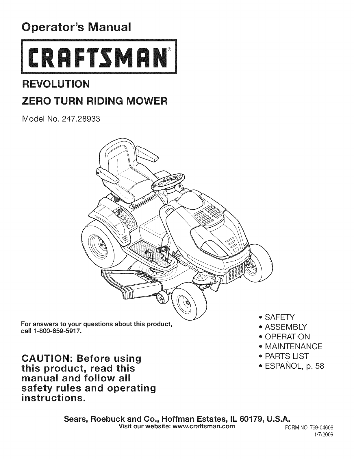
Operator's Manual
CRRFr MRN
REVOLUTION
ZERO TURN RiDiNG MOWER
Model No. 247.28933
For answers to your questions about this product,
call 1-800-659-5917.
CAUTION: Before using
this product, read this
manual and follow all
safety rules and operating
instructions.
Sears, Roebuck and Co., Hoffman Estates, IL 60179, U.S.A.
Visit our website: www.craftsman.com FORMNO.769-04608
o SAFETY
ASSEMBLY
OPERATION
MAINTENANCE
PARTS LIST
ESPANOL, p. 58
1/7/2009
Page 2
WarrantyStatement.................... Page2
SafeOperationPractices.............. Pages3-8
SafetyLabels......................... Page9
Assembly........................... Page10
Operation........................ Pages11-17
Service&Maintenance.............. Pages18-29
Off-SeasonStorage................... Page30
Troubleshooting...................... Page31
PartsList......................... Pages32-53
RepairProtectionAgreement............ Page57
Espadol............................. Page58
ServiceNumbers................... BackPage
Craftsman Limited Warranty
Two Years on Riding Equipment
Whenoperatedand maintainedaccordingto allsuppliedinstructions,ifthis ridingequipmentfailsduetoa defectin materialorworkmanship
withintwoyearsfromthedateorpurchase,call1-800-4-MY-HOME®toarrangefor freerepair.
Duringthefirstyearofpurchase,therewillbe nochargeforwarrantyserviceinyourhome.Foryourconvenience,in-homewarrantyservicewill
stillbeavailableafterthefirstyearof purchase,butatripchargewillapply.Thischargewillbe waivedif youtransportthe ridingequipmenttoan
authorizedCraftsmandrop-offlocation.Forthenearestauthorizedlocation,call 1-800-4-MY-HOME®.
90 Days on Battery
Forninety(90)daysfromdateofpurchase,ifthebatteryincludedwiththisridingequipmentisdefectiveinmaterialorworkmanship(ourtesting
provesitwill notholdacharge),it willbe replacedfreeofchargein yourhome.
This warranty covers ONLYdefects in material andworkmanship. Searswill NOTpayfor:
• Expendableitemsthatbecomewornduringnormaluse,includingbutnotlimitedtoblades,sparkplugs,aircleaners,belts,andoil filters.
• Standardmaintenanceservicing,oilchanges,or tune-ups.
• Tirereplacementor repaircausedbypuncturesfromoutsideobjects,suchasnails,thorns,stumps,or glass.
• Tireor wheelreplacementor repairresultingfromnormalwear,accident,orimproperoperationor maintenance.
• Repairsnecessarybecauseof operatorabuse,includingbutnotlimitedtodamagecausedbytowingobjectsbeyondthecapabilityofthe
ridingequipment,impactingobjectsthatbendtheframeor crankshaft,or over-speedingthe engine.
• Repairsnecessarybecauseof operatornegligence,includingbut notlimitedto,electricalandmechanicaldamagecausedby improper
storage,failureto usethe propergradeandamountofengineoil,failuretokeepthedeckclearofflammabledebris,orfailuretomaintainthe
ridingequipmentaccordingtotheinstructionscontainedin theoperator'smanual.
• Engine(fuelsystem)cleaningorrepairscausedbyfuel determinedto becontaminatedoroxidized(stale).In general,fuelshouldbeused
within30 daysof itspurchasedate.
• Normaldeteriorationandwearof theexteriorfinishes,or productlabelreplacement.
All ridingequipmentandbatterywarrantycoverageis voidif thisproductis everusedforcommercialor rentalpurposes.
Thiswarrantyappliesonlywhilethisproductiswithinthe UnitedStates.
Thiswarrantygivesyouspecificlegalrights,andyoumayalso haveotherrightswhichvaryfromstatetostate.
Sears, RoebuckandCo.,Hoffman Estates, IL 60179
GrossHP: 22
EngineOil: SAE30
Fuel: UnleadedGasoline
SparkPlug: Champion®RC12YC
Engine: Briggs& StrattonIntekV-Twin
©SearsBrands,LLC
ModelNumber.................................................................
Serial Number.................................................................
Dateof Purchase.............................................................
Recordthemodelnumber,serialnumber
anddateof purchaseabove
2
Page 3
Thissymbolpointsout importantsafetyinstructionswhich,if not
followed,couldendangerthepersonalsafetyand/orpropertyof
yourselfandothers. Readandfollowall instructionsin thismanual
beforeattemptingto operatethismachine.Failuretocomplywith
theseinstructionsmayresultinpersonalinjury.Whenyouseethis
symbol,HEEDITSWARNING!
Thismachinewasbuilttobeoperatedaccordingtothe safeopera-
tionpracticesinthismanual.Aswithanytypeof powerequipment,
carelessnessorerroronthepartofthe operatorcanresultin serious
injury.Thismachineiscapableof amputatingfingers,hands,toes
andfeetandthrowingdebris.Failuretoobservethefollowingsafety
instructionscouldresultin seriousinjuryor death.
CALIFORNIA PROPOSITION 65
EngineExhaust,someof itsconstituents,andcertainvehicle
componentscontainoremitchemicalsknownto StateofCalifornia
tocausecancerandbirthdefectsorother reproductiveharm.
Batteryposts,terminals,and relatedaccessoriescontainleadand
leadcompounds,chemicalsknownto theStateof Californiato
causecancerandreproductiveharm.Washhandsafterhandling.
GENERAL OPERATION
• Read,understand,andfollowall instructionson the machineand
in themanual(s)beforeattemptingtoassembleandoperate.
Keepthis manualina safeplacefor futureand regularreference
andfororderingreplacementparts.
• Befamiliarwithall controlsandtheirproperoperation.Knowhow
tostopthemachineanddisengagethemquickly.
• Neverallowchildrenunder14yearsoldtooperatethis machine.
Children14yearsoldandovershouldreadandunderstandthe
operationinstructionsandsafetyrulesinthismanualandshould
betrainedandsupervisedbya parent.
• Neverallowadultstooperatethismachinewithoutproper
instruction.
• Tohelpavoidbladecontactor a thrownobjectinjury,keep
bystanders,helpers,childrenandpetsatleast75feetfromthe
machinewhileitis in operation.Stopmachineifanyoneenters
thearea.
• Thoroughlyinspecttheareawheretheequipmentistobe used.
Removeallstones,sticks,wire,bones,toys,andotherforeign
objectswhichcouldbe pickedupandthrownbytheblade(s).
Thrownobjectscancauseseriouspersonalinjury.
• Planyourmowingpatterntoavoiddischargeof materialtoward
roads,sidewalks,bystandersandthe like.Also,avoiddischarg-
ingmaterialagainstawallorobstructionwhichmaycause
dischargedmaterialto ricochetbacktowardtheoperator.
Your Responsibility--Restrict theuseofthispowermachineto
personswhoread,understandandfollowthewarningsand instruc-
tionsin thismanualandonthemachine.
SAVE THESE INSTRUCTIONS!
• Alwayswearsafetyglassesorsafetygogglesduringoperation
andwhileperforminganadjustmentor repairto protectyoureyes.
Thrownobjectswhichricochetcancauseseriousinjurytothe
eyes.
• Wearsturdy,rough-soledworkshoesandclose-fittingslacksand
shirts.Loosefittingclothesandjewelrycanbe caughtin movable
parts.Neveroperatethismachineinbarefeetorsandals.
• Beawareofthemowerandattachmentdischargedirectionand
do notpointitatanyone.Donotoperatethemowerwithoutthe
dischargecoverorentiregrasscatcherinitsproperplace.
Donot puthandsor feetnearrotatingpartsorunderthecutting
deck.Contactwiththe blade(s)can amputatehandsandfeet.
A missingordamageddischargecovercancausebladecontact
or thrownobjectinjuries.
• Stoptheblade(s)whencrossinggraveldrives,walks,orroads
andwhilenotcuttinggrass.
• Watchfortrafficwhenoperatingnearorcrossingroadways.This
machineisnotintendedforuseonanypublicroadway.
• Donot operatethemachinewhile undertheinfluenceofalcohol
or drugs.
• Mowonlyindaylightorgoodartificiallight.
Nevercarrypassengers.
• Disengageblade(s)beforeshiftingintoreverse.Backupslowly.
Alwayslookdownandbehindbeforeandwhile backingtoavoida
back-overaccident.
3
Page 4
• Slowdownbeforeturning.Operatethemachinesmoothly.Avoid
erraticoperationandexcessivespeed.
Disengageblade(s),setparkingbrake,stopengineandwaituntil
theblade(s)cometoacompletestopbeforeremovinggrass
catcher,emptyinggrass,uncloggingchute,removinganygrassor
debris,or makinganyadjustments.
Neverleavea runningmachineunattended.Alwaysturnoff
blade(s),setparkingbrake,stopengineandremovekeybefore
dismounting.
Useextracarewhenloadingorunloadingthe machineintoa
trailerortruck.Thismachineshouldnot bedrivenupor down
ramp(s),becausethemachinecouldtip over,causingserious
personalinjury.Themachinemustbe pushedmanuallyon
ramp(s)to loador unloadproperly.
Mufflerandenginebecomehotandcancauseaburn.Do not
touch.
Checkoverheadclearancescarefullybeforedrivingunderlow
hangingtreebranches,wires,dooropeningsetc.,wherethe
operatormaybestruckor pulledfromthemachine,whichcould
resultinseriousinjury.
Disengageallattachmentclutchesanddepressthebrakepedal
completelybeforeattemptingtostart engine.
Yourmachineisdesignedto cutnormalresidentialgrassofa
heightnomorethan10".Donotattemptto mowthroughunusually
tall,drygrass(e.g.,pasture)orpilesofdryleaves.Drygrassor
leavesmaycontacttheengineexhaustand/orbuilduponthe
mowerdeckpresentinga potentialfirehazard.
Useonlyaccessoriesandattachmentsapprovedforthis machine
bythe machinemanufacturer.Read,understandandfollowall
instructionsprovidedwiththeapprovedaccessoryorattachment.
Fora list ofapprovedaccessoriesandattachments,call 1-800-
659-5917.
Dataindicatesthatoperators,age60yearsandabove,are
involvedin a largepercentageofridingmower-relatedinjuries.
Theseoperatorsshouldevaluatetheirabilitytooperatetheriding
mowersafelyenoughto protectthemselvesandothersfrom
seriousinjury.
If situationsoccurwhicharenot coveredinthismanual,usecare
andgoodjudgment.Contact1-800-659-5917forinformationand
assistance.
SLOPE OPERATION
Slopesarea majorfactorrelatedtolossofcontrolandtip-over
accidentswhichcanresultinsevereinjuryor death.Allslopesrequire
extracaution.Ifyoucannotbackupthe slopeor if youfeeluneasyon
it, do notmowit.
Foryoursafety,usetheSlopeGuideincludedaspartof this manual
to measureslopesbeforeoperatingthismachineona slopedor hilly
area.Iftheslopeisgreaterthan15degreesasshownonthe Slope
Guide,do notoperatethismachineonthatareaor seriousinjurycould
result.
Do:
o
Mowupanddownslopes,not across.Exerciseextremecaution
whenchangingdirectionon slopes.
• Watchforholes,ruts,bumps,rocks,orotherhiddenobjects.
Uneventerraincouldoverturnthemachine.Tallgrasscanhide
obstacles.
Useslowspeed.Choosea lowenoughspeedsettingsothat
youwill nothavetostopor shiftwhileon theslope.Tiresmay
losetractionon slopeseventhoughthe brakesarefunctioning
properly.Alwayskeepmachineingearwhen goingdownslopes
totakeadvantageofenginebrakingaction.
• Followthemanufacturer'srecommendationsforwheelweights
or counterweightsto improvestability.Forrecommendations,call
1-800-659-5917.
• Useextracarewithgrasscatchersor otherattachments.These
canchangethestabilityofthe machine.
Keepallmovementonthe slopesslowandgradual.Donotmake
suddenchangesinspeedor direction.Rapidengagementor
brakingcouldcausethefrontofthemachinetoliftandrapidlyflip
overbackwardswhichcouldcauseseriousinjury.
• Avoidstartingorstoppingona slope.Iftireslosetraction,disen-
gagetheblade(s)andproceedslowlystraightdowntheslope.
DoNot:
• Donot turnon slopesunlessnecessary;then,turnslowlyand
graduallydownhill,ifpossible.
• Donot mowneardrop-offs,ditchesorembankments.The mower
couldsuddenlyturnoverif a wheelisovertheedgeofa cliff,
ditch,or if an edgecavesin.
• Donot try tostabilizethemachinebyputtingyourfooton the
ground.
• Donot usea grasscatcheronsteepslopes.
• Donot mowon wetgrass.Reducedtractioncouldcausesliding.
• Donot attempttocoastdownhill.Over-speedingmaycausethe
operatortolosecontrolofthemachineresultingin seriousinjury
or death.
• Donot towheavypull behindattachments(e.g.loadeddumpcart,
lawnroller,etc.)on slopesgreaterthan5degrees.Whengoing
downhill,theextraweighttendstopushthetractorandmay
causeyouto loosecontrol.(e.g.tractormayspeedup,braking
and steeringabilityare reduced,attachmentmayjack-knifeand
causetractorto overturn).
4
Page 5
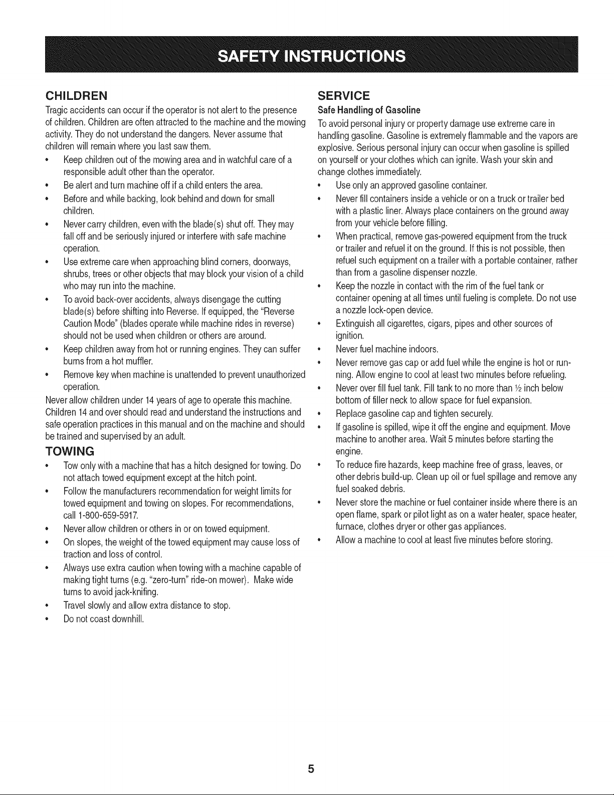
CHILDREN
Tragicaccidentscanoccurifthe operatorisnotalert tothepresence
ofchildren.Childrenareoftenattractedto themachineandthemowing
activity.Theydo notunderstandthedangers.Neverassumethat
childrenwillremainwhereyoulastsawthem.
• Keepchildrenoutofthe mowingareaand inwatchfulcare ofa
responsibleadultotherthantheoperator.
• Bealertandturnmachineoff ifachildentersthe area.
• Beforeandwhilebacking,lookbehindanddownfor small
children.
Nevercarrychildren,evenwiththeblade(s)shutoff.Theymay
falloffandbeseriouslyinjuredorinterferewithsafemachine
operation.
• Useextremecarewhenapproachingblindcorners,doorways,
shrubs,treesorotherobjectsthatmayblockyourvisionof a child
whomayrunintothe machine.
Toavoidback-overaccidents,alwaysdisengagethecutting
blade(s)beforeshiftingintoReverse.Ifequipped,the"Reverse
CautionMode"(bladesoperatewhilemachineridesinreverse)
shouldnotbe usedwhenchildrenorothersarearound.
Keepchildrenawayfromhotor runningengines.Theycansuffer
burnsfroma hotmuffler.
• Removekeywhenmachineisunattendedto preventunauthorized
operation.
Neverallowchildrenunder14yearsofagetooperatethis machine.
Children14andovershouldreadandunderstandtheinstructionsand
safeoperationpracticesinthismanualandon themachineandshould
betrainedandsupervisedbyan adult.
TOWING
Towonlywitha machinethathasa hitchdesignedfor towing.Do
notattachtowedequipmentexceptat thehitchpoint.
Followthemanufacturersrecommendationforweightlimitsfor
towedequipmentandtowingonslopes.Forrecommendations,
call1-800-659-5917.
Neverallowchildrenor othersinoron towedequipment.
Onslopes,theweightof thetowedequipmentmaycauselossof
tractionandlossof control.
Alwaysuseextracautionwhentowingwitha machinecapableof
makingtightturns(e.g."zero-turn"ride-onmower). Makewide
turnstoavoidjack-knifing.
Travelslowlyandallowextradistancetostop.
Donotcoastdownhill.
SERVICE
SafeHandlingof Gasoline
Toavoidpersonalinjuryorpropertydamageuseextremecarein
handlinggasoline.Gasolineisextremelyflammableandthevaporsare
explosive.Seriouspersonalinjurycanoccurwhengasolineis spilled
on yourselforyour clotheswhichcanignite.Washyourskinand
changeclothesimmediately.
• Useonlyanapprovedgasolinecontainer.
Neverfillcontainersinsidea vehicleoron a truckortrailer bed
witha plasticliner.Alwaysplacecontainerson thegroundaway
fromyourvehiclebeforefilling.
Whenpractical,removegas-poweredequipmentfromthe truck
or trailerandrefuelitontheground.Ifthis isnot possible,then
refuelsuchequipmentona trailerwitha portablecontainer,rather
thanfroma gasolinedispensernozzle.
Keepthenozzleincontactwiththe rimofthe fueltankor
containeropeningatalltimesuntilfuelingiscomplete.Donot use
a nozzlelock-opendevice.
Extinguishall cigarettes,cigars,pipesandothersourcesof
ignition.
• Neverfuelmachineindoors.
Neverremovegascapor addfuelwhiletheengineis hotor run-
ning.Allowengineto coolatleasttwominutesbeforerefueling.
Neveroverfillfuel tank.Filltanktonomorethan1/2inchbelow
bottomoffillernecktoallowspaceforfuel expansion.
• Replacegasolinecapandtightensecurely.
• Ifgasolineisspilled,wipeitoff the engineandequipment.Move
machinetoanotherarea.Wait5 minutesbeforestartingthe
engine.
• Toreducefirehazards,keepmachinefreeofgrass,leaves,or
otherdebrisbuild-up.Cleanup oilor fuelspillageandremoveany
fuelsoakeddebris.
• Neverstorethemachineorfuelcontainerinsidewherethereisan
openflame,sparkor pilotlightasonawaterheater,spaceheater,
furnace,clothesdryeror othergasappliances.
Allowa machineto coolatleastfiveminutesbeforestoring.
Page 6
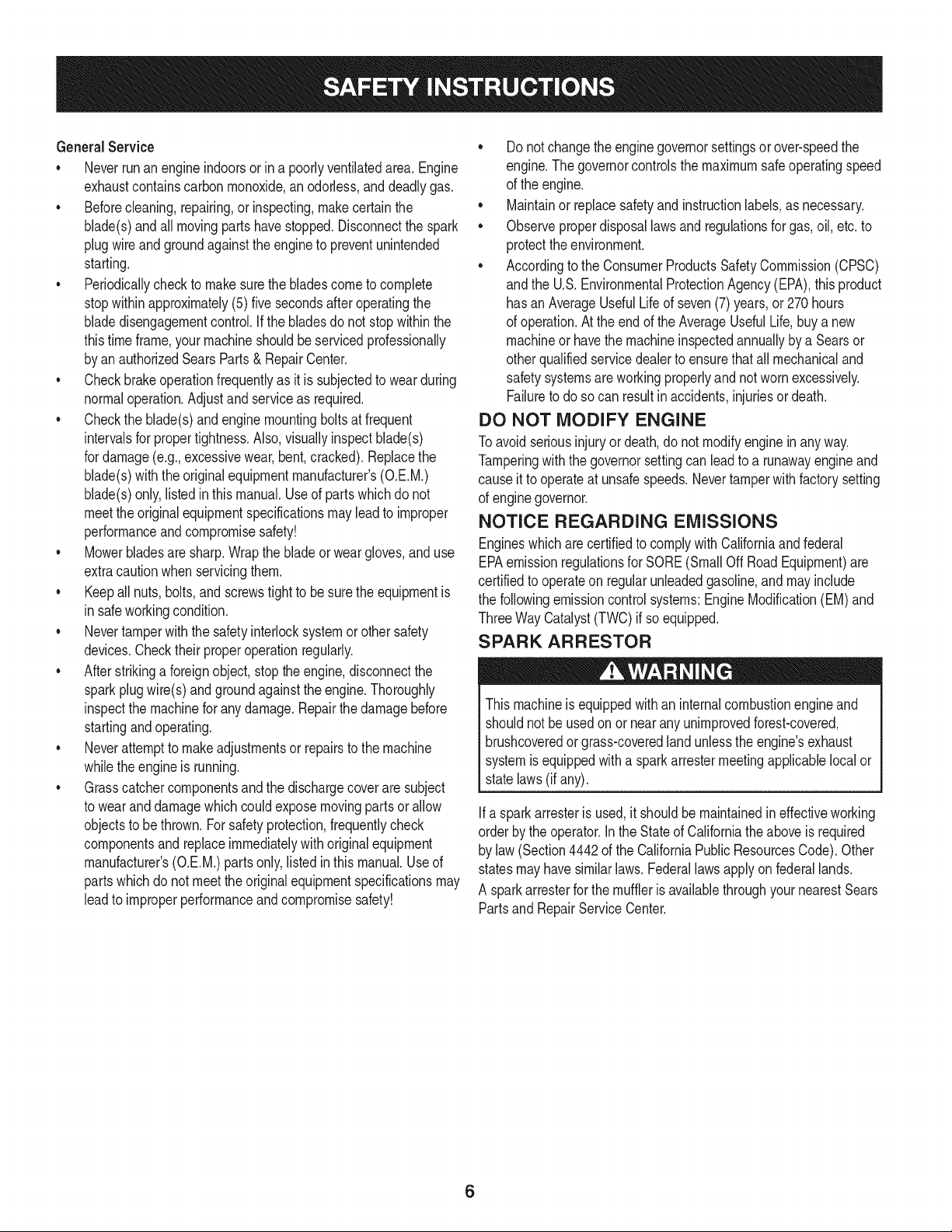
GeneralService
• Neverrunanengineindoorsorinapoorlyventilatedarea.Engine
exhaustcontainscarbonmonoxide,anodorless,anddeadlygas.
• Beforecleaning,repairing,orinspecting,makecertainthe
blade(s)andallmovingpartshavestopped.Disconnectthespark
plugwireandgroundagainsttheenginetopreventunintended
starting.
• Periodicallychecktomakesurethebladescometocomplete
stopwithinapproximately(5)fivesecondsafteroperatingthe
bladedisengagementcontrol.Ifthebladesdonotstopwithinthe
thistimeframe,yourmachineshouldbeservicedprofessionally
byanauthorizedSearsParts&RepairCenter.
• Checkbrakeoperationfrequentlyasitissubjectedtowearduring
normaloperation.Adjustandserviceasrequired.
• Checktheblade(s)andenginemountingboltsatfrequent
intervalsforpropertightness.Also,visuallyinspectblade(s)
fordamage(e.g.,excessivewear,bent,cracked).Replacethe
blade(s)withtheoriginalequipmentmanufacturer's(O.E.M.)
blade(s)only,listedinthismanual.Useofpartswhichdonot
meettheoriginalequipmentspecificationsmayleadtoimproper
performanceandcompromisesafety!
• Mowerbladesaresharp.Wrapthebladeorweargloves,anduse
extracautionwhenservicingthem.
• Keepallnuts,bolts,andscrewstighttobesuretheequipmentis
insafeworkingcondition.
• Nevertamperwiththesafetyinterlocksystemorothersafety
devices.Checktheirproperoperationregularly.
• Afterstrikingaforeignobject,stopthe engine,disconnectthe
sparkplugwire(s)andgroundagainsttheengine.Thoroughly
inspectthemachineforanydamage.Repairthedamagebefore
startingandoperating.
• Neverattempttomakeadjustmentsor repairstothe machine
whilethe engineis running.
• Grasscatchercomponentsandthe dischargecoverare subject
towearanddamagewhichcouldexposemovingpartsor allow
objectsto bethrown.Forsafetyprotection,frequentlycheck
componentsand replaceimmediatelywithoriginalequipment
manufacturer's(O.E.M.)partsonly,listedinthis manual.Useof
partswhichdo notmeettheoriginalequipmentspecificationsmay
leadtoimproperperformanceandcompromisesafety!
• Donot changetheenginegovernorsettingsorover-speedthe
engine.Thegovernorcontrolsthemaximumsafeoperatingspeed
ofthe engine.
Maintainor replacesafetyandinstructionlabels,asnecessary.
• Observeproperdisposallawsandregulationsforgas,oil,etc.to
protecttheenvironment.
• Accordingtothe ConsumerProductsSafetyCommission(CPSC)
andthe U.S.EnvironmentalProtectionAgency(EPA),thisproduct
hasanAverageUsefulLifeof seven(7)years,or270hours
ofoperation.Attheendofthe AverageUsefulLife,buyanew
machineor havethemachineinspectedannuallybya Searsor
otherqualifiedservicedealerto ensurethatall mechanicaland
safetysystemsareworkingproperlyandnotwornexcessively.
Failuretodosocanresultinaccidents,injuriesor death.
DO NOT MODIFY ENGINE
Toavoid seriousinjuryor death,do notmodifyengineinanyway.
Tamperingwiththegovernorsettingcanleadto a runawayengineand
causeittooperateat unsafespeeds.Nevertamperwithfactorysetting
ofenginegovernor.
NOTICE REGARDING EMISSIONS
Engineswhicharecertifiedto complywithCaliforniaandfederal
EPAemissionregulationsforSORE(SmallOffRoadEquipment)are
certifiedto operateonregularunleadedgasoline,andmayinclude
thefollowingemissioncontrolsystems:EngineModification(EM)and
ThreeWayCatalyst(TWO)if soequipped.
SPARK ARRESTOR
Thismachineis equippedwithan internalcombustionengineand
shouldnotbe usedonornearanyunimprovedforest-covered,
brushcoveredorgrass-coveredlandunlesstheengine'sexhaust
systemisequippedwitha sparkarrestermeetingapplicablelocalor
statelaws(if any).
Ifa sparkarresteris used,itshouldbe maintainedin effectiveworking
orderbytheoperator.IntheStateof Californiatheaboveisrequired
bylaw (Section4442of theCaliforniaPublicResourcesCode).Other
statesmayhavesimilarlaws.Federallawsapplyonfederallands.
A sparkarresterforthemufflerisavailablethroughyournearestSears
PartsandRepairServiceCenter.
6
Page 7
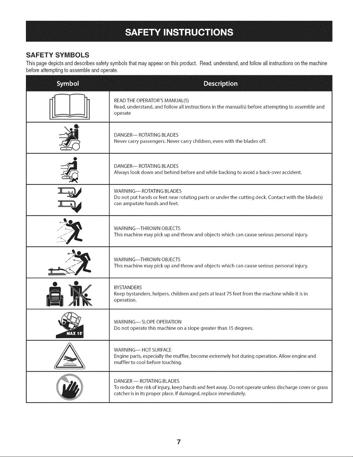
SAFETY SYMBOLS
Thispagedepictsanddescribessafetysymbolsthatmayappearonthisproduct.Read,understand,andfollowallinstructionson the machine
beforeattemptingto assembleandoperate.
READ THE OPERATOR'S MANUAL(S)
Read, understand, and follow all instructions in the manual(s) before attempting to assemble and
operate
DANGER-- ROTATING BLADES
Never carry passengers. Never carry children, even with the blades off.
0
DANGER-- ROTATING BLADES
Always look down and behind before and while backing to avoid a back-over accident.
WARNING-- ROTATING BLADES
Do not put hands or feet near rotating parts or under the cutting deck. Contact with the blade(s)
can amputate hands and feet.
A
WARNING--THROWN OBJECTS
This machine may pick up and throw and objects which can cause serious personal injury.
WARNING--THROWN OBJECTS
This machine may pick up and throw and objects which can cause serious personal injury.
BYSTANDERS
Keep bystanders, helpers, children and pets at least 75 feet from the machine while it is in
operation.
WARNING-- SLOPE OPERATION
Do not operate this machine on a slope greater than 15 degrees.
WARNING-- HOT SURFACE
Engine parts, especially the muffler, become extremely hot during operation. Allow engine and
muffler to cool before touching.
DANGER-- ROTATING BLADES
To reduce the risk of injury, keep hands and feet away. Do not operate unless discharge cover or grass
catcher is in its proper place. If damaged, replace immediately.
7
Page 8
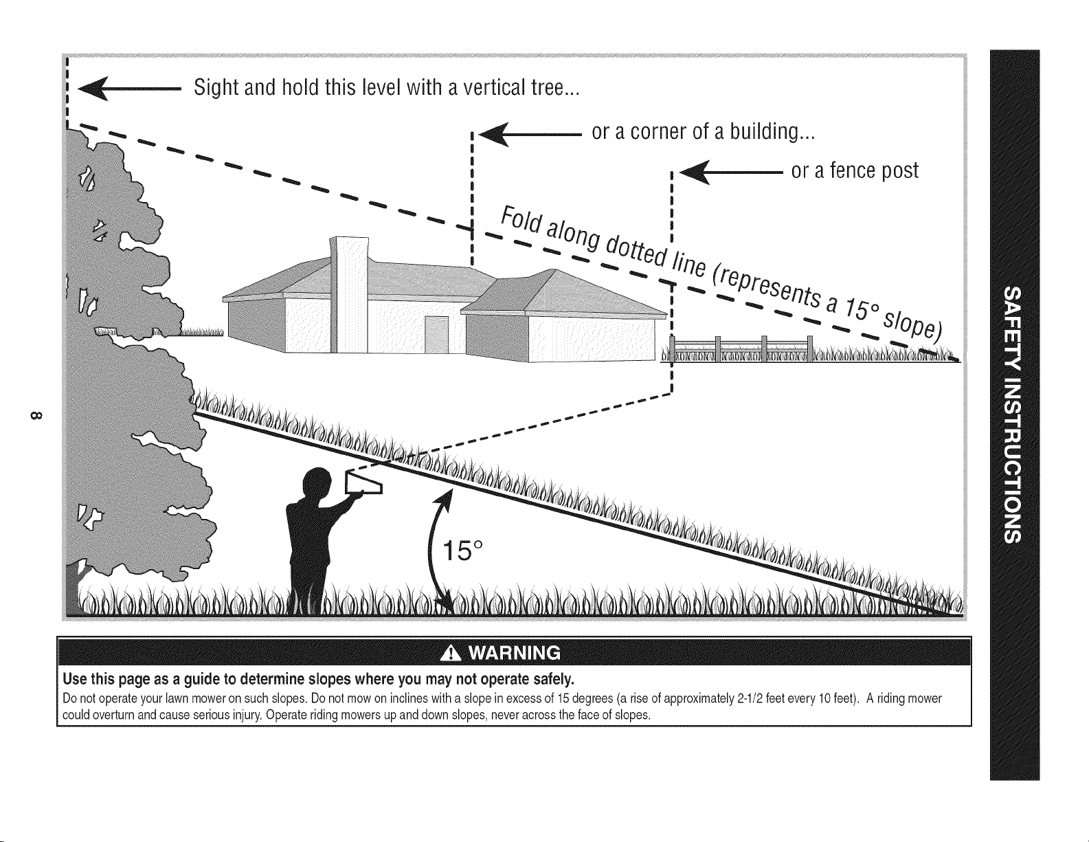
Sightandholdthis levelwith averticaltree...
|
|
|
!
!
|
|
or acorner of a building...
,_ or afencepost
|
|
#Old ',
!
|
0o
_. :,uog dotto,_'.
"T,"_ _Presen_ts
alo
, ._ _lOpe_
|
I
15 °
Use this page as a guideto determine slopes whereyou may not operate safely.
Donot operateyourlawnmoweron suchslopes.Do notmowoninclineswitha slopeinexcessof 15degrees(a riseofapproximately2-1/2feetevery10feet). A ridingmower
couldoverturnandcauseseriousinjury.Operateridingmowersupanddownslopes,neveracrossthefaceofslopes.
Page 9
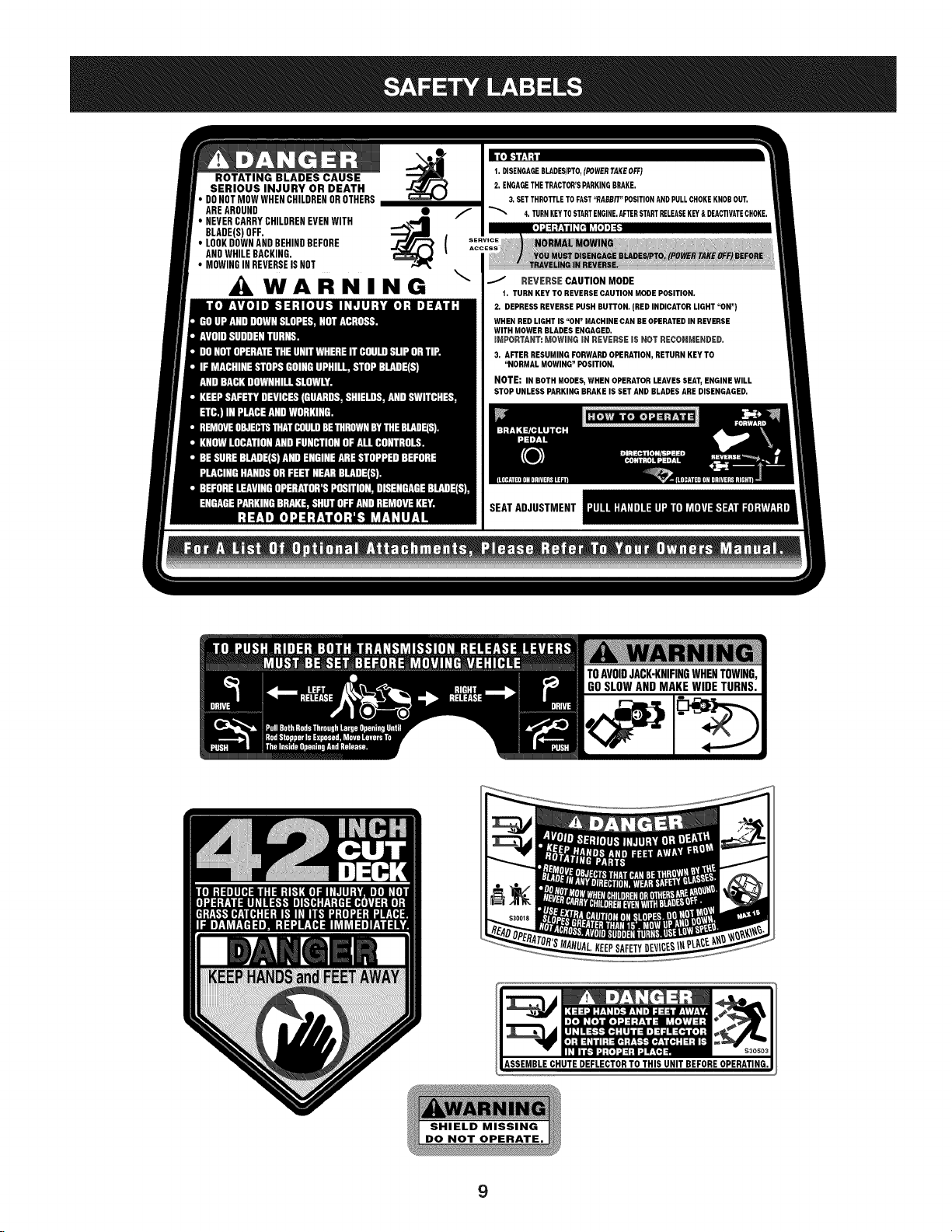
ROTATING BLADES CAUSE
SERIOUS INJURY OR DEATH
DONOTMOWWHENCHILDRENDROTHERS
AREAROUND
• NEVERCARRYCHILDRENEVENWITH
BLADE(S)OFF.
• LOOKDOWNANDBEHINDBEFORE
ANDWHILEBACKING.
* MOWINGINREVERSEISNOT
_WARNING
1.DISENGAGEBLADES/PTO,(POWERTAKEOFF)
2, ENGAGETHETRACTOR'SPARKINGBRAKE.
3.SETTHROTTLETOFAST"RABBIT"POSITIONANDPULLCHOKEKNOBOUT.
;. TURNKEYTOSTARTENGINE.AFTERSTARTRELEASEKEY&DEACTIVATECHOKE.
REVERSE CAUTION MODE
t. TURN KEYTO REVERSECAUTIONMODEPOSITION,
2, DEPRESSREVERSEPUSHBUTTON,(RED INDICATORLIGHT "ON")
WHENREDLIGHTIS "ON" MACHINECANBEOPERATEDIN REVERSE
WITHMOWERBLADESENGAGED.
mMPORTANT:MOWING iN REVERSEiS NOT RECOMMENDED.
3, AFTERRESUMINGFORWARDOPERATION,RETURNKEYTO
"NORMALMOWING"POSITION,
NOTE: IN BOTH MODES,WHEN OPERATORLEAVESSEAT,ENGINEWILL
STOPUNLESSPARKINGBRAKEIS SETANDBLADESAREDISENGAGED,
9
Page 10
IMPORTANT:Yourtractorisshippedwithmotoroil in theengine.
However,youMUSTcheckthe oil levelbeforeoperating.Referto the
Service& Maintenancesectionforinstructionson checkingtheoil
level.
OPENING THE TRACTOR HOOD
Toattachthebatterycablesandchecktheengineoil levelthehood
mustbeopen. Locatethe hoodlift notch(Referto Figure2on page11)
atthe front/centerofthe dashpanel.Graspingthehoodat thenotch,
lift andpivotthehoodforwardtoopen.
ATTACHING THE BATTERY CABLES
CALIFORNIA PROPOSITION 65
Batteryposts,terminals,andrelatedaccessoriescontainleadand
leadcompounds,chemicalsknownto theStateof Californiato
causecancerandreproductiveharm.Washhandsafterhandling.
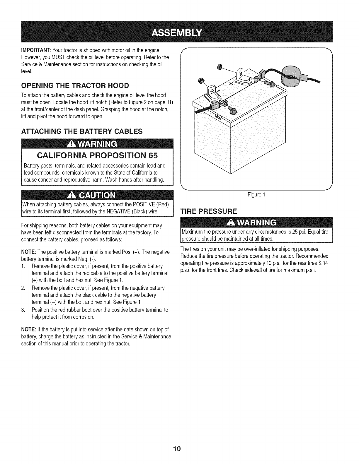
Whenattachingbatterycables,alwaysconnectthePOSITIVE(Red)
wireto its terminalfirst,followedby theNEGATIVE(Black)wire.
Figure1
TIRE PRESSURE
Forshippingreasons,bothbatterycablesonyourequipmentmay
havebeenleftdisconnectedfromtheterminalsatthefactory.To
connectthebatterycables,proceedasfollows:
NOTE:ThepositivebatteryterminalismarkedPos.(+).Thenegative
batteryterminalis markedNeg.(-).
1. Removethe plasticcover,if present,fromthe positivebattery
terminaland attachthe redcableto the positivebatteryterminal
(+)withthebolt andhexnut.See Figure1.
2. Removethe plasticcover,if present,fromthe negativebattery
terminaland attachtheblackcabletothenegativebattery
terminal(-) withthe boltandhexnut.SeeFigure1.
3. Positionthe redrubberbootoverthepositivebatteryterminalto
helpprotectit fromcorrosion.
NOTE:If thebatteryisputintoserviceafterthedateshownon topof
battery,chargethebatteryas instructedinthe Service& Maintenance
sectionofthis manualpriortooperatingthetractor.
3ressureshouldbemaintainedatall times.
Thetiresonyourunitmaybeover-inflatedforshippingpurposes.
Reducethetirepressurebeforeoperatingthe tractor.Recommended
operatingtirepressureisapproximately10p.s.iforthe reartires & 14
p.s.i,forthe fronttires.Checksidewalloftirefor maximump.s.i.
10
Page 11
f
Q
A
\
C
E
P
K
L--
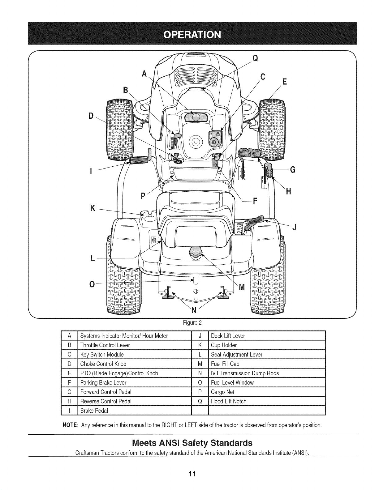
A SystemsIndicatorMonitor/HourMeter
B ThrottleControlLever
C KeySwitchModule
D ChokeControlKnob
E PTO(BladeEngage)ControlKnob
F ParkingBrakeLever
G ForwardControlPedal
H ReverseControlPedal
I BrakePedal
F
J
Figure2
J DeckLiftLever
K CupHolder
L SeatAdjustmentLever
M FuelFillCap
N IVTTransmissionDumpRods
0 FuelLevelWindow
P CargoNet
Q HoodLiftNotch
NOTE: Any referenceinthismanualtotheRIGHTorLEFTside ofthe tractorisobservedfromoperator'sposition.
Meets ANSI Safety Standards
CraftsmanTractorsconformtothesafetystandardof theAmericanNationalStandardsInstitute(ANSI).
11
Page 12
SYSTEMS iNDiCATOR MONITOR/HOUR
METER
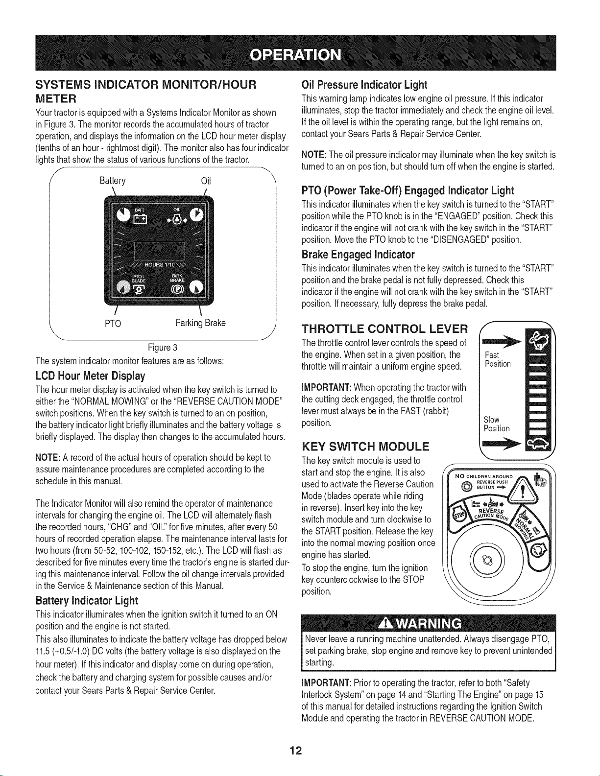
Yourtractorisequippedwitha SystemsIndicatorMonitoras shown
in Figure3.Themonitorrecordstheaccumulatedhoursoftractor
operation,anddisplaystheinformationontheLCDhourmeterdisplay
(tenthsofan hour- rightmostdigit).The monitoralsohasfour indicator
lightsthat showthestatusofvariousfunctionsof thetractor.
Battery Oil
Oil PressureindicatorLight
Thiswarninglampindicateslowengineoil pressure.Ifthisindicator
illuminates,stopthetractorimmediatelyandchecktheengineoil level.
Iftheoilleveliswithintheoperatingrange,butthelight remainson,
contactyourSearsParts& RepairServiceCenter.
NOTE:The oilpressureindicatormayilluminatewhenthe keyswitchis
turnedto an onposition,butshouldturnoff whentheengineisstarted.
PTO(Power Take-Off) Engaged indicatorLight
Thisindicatorilluminateswhenthekeyswitchisturnedtothe"START"
positionwhilethe PTOknobisinthe"ENGAGED"position.Checkthis
indicatorif theenginewillnotcrankwiththekeyswitchinthe"START"
position.Movethe PTOknobtothe"DISENGAGED"position.
Brake Engaged indicator
Thisindicatorilluminateswhenthekeyswitchisturnedtothe"START"
positionandthebrakepedalisnotfullydepressed.Checkthis
indicatoriftheenginewillnotcrankwiththekeyswitchinthe"START"
position.If necessary,fullydepressthebrakepedal.
PTO ParkingBrake
"-.. j
Figure3
Thesystemindicatormonitorfeaturesareasfollows:
LCD Hour Meter Display
Thehourmeterdisplayis activatedwhenthe keyswitchisturnedto
eitherthe"NORMALMOWING"orthe"REVERSECAUTIONMODE"
switchpositions.Whenthekeyswitchis turnedto anon position,
thebatteryindicatorlight brieflyilluminatesandthe batteryvoltageis
bridly displayed.Thedisplaythenchangesto theaccumulatedhours.
NOTE:A recordoftheactualhoursofoperationshouldbekeptto
assuremaintenanceproceduresarecompletedaccordingtothe
scheduleinthismanual.
TheIndicatorMonitorwillalsoremindtheoperatorofmaintenance
intervalsforchangingtheengineoil.The LCDwillalternatelyflash
therecordedhours,"CHG"and"Oil" for fiveminutes,afterevery50
hoursof recordedoperationelapse.The maintenanceintervallastsfor
twohours(from50-52,100-102,150-152,etc.).The LCDwillflashas
describedforfiveminuteseverytimethe tractor'sengineisstarteddur-
ingthis maintenanceinterval.Followthe oilchangeintervalsprovided
inthe Service& Maintenancesectionof thisManual.
Battery indicator Light
ThisindicatorilluminateswhentheignitionswitchitturnedtoanON
positionandtheengineis notstarted.
Thisalsoilluminatesto indicatethebatteryvoltagehasdroppedbelow
11.5(+0.5/-1.0)DCvolts(the batteryvoltageisalsodisplayedonthe
hourmeter).Ifthisindicatorand displaycomeonduringoperation,
checkthe batteryandchargingsystemforpossiblecausesand/or
contactyourSearsParts& RepairServiceCenter.
THROTTLE CONTROL LEVER
Thethrottlecontrollevercontrolsthespeedof
theengine.Whenset inagivenposition,the
throttlewill maintaina uniformenginespeed.
IMPORTANT:Whenoperatingthetractorwith
thecuttingdeckengaged,thethrottlecontrol
levermustalwaysbeintheFAST(rabbit)
position.
Fast
Position
Slow
Position
KEY SWITCH MODULE
Thekeyswitchmoduleisusedto
startandstoptheengine.Itisalso
usedto activatetheReverseCaution
Mode(bladesoperatewhileriding
in reverse).Insertkeyintothekey
switchmoduleandturn clockwiseto
theSTARTposition.Releasethe key
intothenormalmowingpositiononce
enginehasstarted.
Tostopthe engine,turntheignition
keycounterclockwiseto theSTOP
position.
Neverleavea runningmachineunattended.AlwaysdisengagePTO,
setparkingbrake,stopengineand removekeyto preventunintended
starting.
IMPORTANT:Priorto operatingthetractor,referto both"Safety
InterlockSystem"on page14and"StartingThe Engine"on page15
ofthis manualfordetailedinstructionsregardingthe IgnitionSwitch
ModuleandoperatingthetractorinREVERSECAUTIONMODE.
@
12
Page 13
NevermovethekeyintotheStartpositionwhiletheengineis
running.Doingsomaycausedamagetoyourengine'sstarter.
CHOKE CONTROL
Thechokecontrolknobislocatedonthe lowerIdt sideofthedash
paneland isactivatedby pullingoutward.Activatingthe chokecontrol
closesthechokeplateonthecarburetorandaidsinstartingthe
engine.
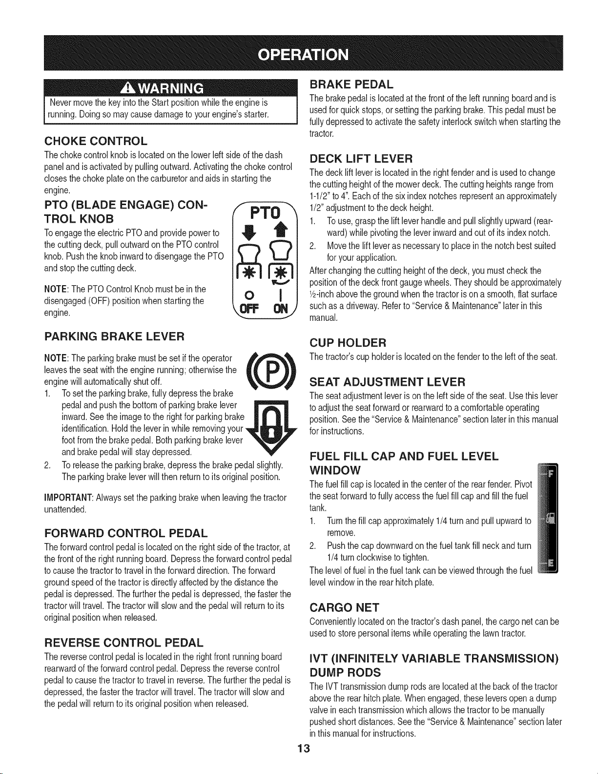
PTO (BLADE ENGAGE) CON-
TROL KNOB
Toengagethe electricPTOand providepowerto
thecuttingdeck,pulloutwardonthePTOcontrol
knob.PushtheknobinwardtodisengagethePTO
andstopthecuttingdeck.
NOTE:The PTOControlKnobmustbe inthe
disengaged(OFF)positionwhenstartingthe
engine.
F PTO
o I
BRAKE PEDAL
Thebrakepedalislocatedatthe frontoftheleft runningboardandis
usedforquickstops,or settingtheparkingbrake.Thispedalmustbe
fullydepressedtoactivatethesafetyinterlockswitchwhen startingthe
tractor.
DECK LIFT LEVER
Thedeckliftleverislocatedintherightfenderandisusedtochange
thecuttingheightof themowerdeck.Thecuttingheightsrangefrom
1-1/2"to 4".Eachofthesix indexnotchesrepresentanapproximately
1/2"adjustmentto thedeckheight.
1. To use,graspthe lift leverhandleandpullslightlyupward(rear-
ward)while pivotingtheleverinwardandoutof its indexnotch.
2. Movethe liftleverasnecessaryto placeinthe notchbestsuited
foryourapplication.
Afterchangingthecuttingheightofthedeck,youmustcheckthe
positionofthedeckfrontgaugewheels.Theyshouldbeapproximately
1/2-inchabovethegroundwhenthetractorisona smooth,flatsurface
suchasa driveway.Referto "Service& Maintenance"laterinthis
manual.
PARKING BRAKE LEVER
NOTE:Theparkingbrakemustbesetifthe operator ,_,_%,
leavestheseatwiththeenginerunning;otherwisethe
enginewillautomaticallyshutoff.
1. Tosettheparkingbrake,fullydepressthebrake
pedaland pushthe bottomofparkingbrakelever
inward.Seetheimagetotherightforparkingbrake
identification.Holdtheleverinwhileremovingyour
footfromthebrakepedal.Bothparkingbrakelever
andbrakepedalwill staydepressed.
2. Toreleasetheparkingbrake,depressthebrakepedalslightly.
Theparkingbrakeleverwillthenreturntoits originalposition.
IMPORTANT:Alwayssettheparkingbrakewhenleavingthetractor
unattended.
tL )
FORWARD CONTROL PEDAL
Theforwardcontrolpedalis locatedonthe rightsideofthetractor,at
thefrontof the rightrunningboard.Depressthe forwardcontrolpedal
tocausethe tractortotravelinthe forwarddirection.Theforward
groundspeedof thetractorisdirectlyaffectedbythedistancethe
pedalisdepressed.Thefurtherthepedalisdepressed,thefasterthe
tractorwilltravel.Thetractorwillslowandthe pedalwillreturnto its
originalpositionwhenreleased.
REVERSE CONTROL PEDAL
Thereversecontrolpedalis locatedinthe rightfrontrunningboard
rearwardoftheforwardcontrolpedal.Depressthe reversecontrol
pedaltocausethetractorto travelin reverse.Thefurtherthepedalis
depressed,the fasterthetractorwilltravel.Thetractorwillslowand
thepedalwill returntoitsoriginalpositionwhenreleased.
CUP HOLDER
Thetractor'scupholderis locatedon thefendertothe left oftheseat.
SEAT ADJUSTMENT LEVER
Theseatadjustmentleverisontheleftside oftheseat.Usethis lever
toadjusttheseatforwardor rearwardtoacomfortableoperating
position.Seethe"Service&Maintenance"sectionlaterin thismanual
forinstructions.
FUEL FILL CAP AND FUEL LEVEL
WINDOW
Thefuelfillcapis locatedinthecenterofthe rearfender.Pivot
theseatforwardtofullyaccessthefuelfill capandfillthefuel
tank.
1. Turnthefill capapproximately1/4turnandpull upwardto
remove.
2. Pushthecapdownwardonthefueltankfillneckandturn
1/4turn clockwisetotighten.
Theleveloffuelinthe fueltankcanbeviewedthroughthefuel
levelwindowinthe rearhitchplate.
CARGO NET
Convenientlylocatedon thetractor'sdashpanel,thecargo netcan be
usedto storepersonalitemswhileoperatingthelawntractor.
IVT (INFINITELY VARIABLE TRANSMISSION)
DUMP RODS
TheIVTtransmissiondumprodsare locatedatthebackof thetractor
abovethe rearhitchplate.Whenengaged,theseleversopena dump
valveineachtransmissionwhichallowsthetractorto bemanually
pushedshortdistances.Seethe"Service& Maintenance"sectionlater
inthismanualfor instructions.
13
Page 14
Avoid Serious injury or Death
• Goupanddownslopes,notacross.
Avoidsuddenturns.
Donotoperatetheunitwhereitcouldslip ortip.
If machinestopsgoinguphill,stopbladesandbackdownhill
slowly.
• Donotmowwhenchildrenorothersarearound.
• Nevercarrychildren,evenwithbladesoff.
• Lookdownandbehindbeforeandwhilebacking.
• Keepsafetydevices(guards,shields,andswitches)inplace
andworking.
• Removeobjectsthatcouldbethrownbythe blades.
• Knowlocationandfunctionofallcontrols.
• Besurebladesandengineare stoppedbeforeplacinghandsor
feetnearblades.
• Beforeleavingoperator'sposition,stoptractor,disengage
blades,engageparkingbrake,shutengineoff,and removekey.
Read Operator's Manual
OIL AND GAS FILL-UP
0il
IMPORTANT:Yourtractorisshippedwithmotoroil in theengine.
However,youMUSTcheckthe oil levelbeforeoperating.Seethe
"ServiceandMaintenance"section.
Gasoline
Useextremecarewhenhandlinggasoline.Gasolineisextremely
flammableandthe vaporsareexplosive.Neverfuel machine
indoorsorwhiletheengineishotor running.Extinguishcigarettes,
cigars,pipes,andothersourcesofignition.
NOTE: Purchasegasolinein smallquantities.Donotusegasolineleft
overfromthe previousseason,tominimizegumdepositsinthe fuel
system.
• Donot overfillfueltank.Filltankto nomorethan1/2inchbelow
bottomof fillernecktoallowspaceforfuelexpansion.
• Neverremovegascapor addfuelwhiletheengineis hotor run-
ning.Allowenginetocoolatleasttwominutesbeforerefueling.
• Ifgasolineis spilled,wipeitoff the engineandequipment.Move
machinetoanotherarea.Wait5 minutesbeforestartingthe
engine.
1. Turntheengineoffandletenginecoolatleast2minutesbefore
removingthefuel cap.Thegasolinetankis underthe rearfender,
withthefuelfillcaplocatedinthe centeroftherearfender.
Thefuelcapistetheredtothetractorto preventitsloss.Donot
attemptto removethecapfromthetractor.
2. Fillthe fueltankwithgasoline.
3. Reinstallthe fuelcap.
SAFETY INTERLOCK SYSTEM
Thesafetyinterlocksystemis designedforsafeoperationofthetrac-
tor.If thissystemshouldevermalfunction,donot operatethetractor,
immediatelycontactyourSearsParts& RepairServiceCenter.
• Thesafetyinterlocksystempreventstheenginefromstarting
unlesstheparkingbrakeisengagedandthe PTOknobis inthe
disengaged(OFF)position.
• Thesafetyinterlocksystemwillautomaticallyshutoffthe engineif
theoperatorleavestheseatbeforeengagingtheparkingbrake.
• Thesafetyinterlocksystemwillautomaticallyshutoffthe engine
if theoperatorleavesthetractor'sseatwiththePTO(Blade
Engage)knobengaged,regardlessofwhethertheparkingbrake
is engaged.
• WiththeignitionkeyintheNORMALMOWINGposition,the
electricPTOclutchwill automaticallyshutoff ifthe PTOknobis in
theengaged(ON) positionandthe drivepedalisdepressedfor
Reversetravel.
Tamperingwithor attemptingto bypasstheSafetyInterlockSwitches
in anywaywillvoidyourtractor'swarranty.Donot operatethetractor
if the interlocksystemis malfunctioning.
REVERSE CAUTION MODE
• Thisengineiscertifiedtooperateon unleadedgasoline.For best
results,fillthe fueltankwithonlyclean,fresh,unleadedgasoline
witha pumpstickeroctaneratingof87or higher.
• Gasohol(upto 10%ethylalcohol,90%unleadedgasolineby
volume)isanapprovedfuel.Othergasoline/alcoholblends,such
asE85,arenotapproved.
• MethylTertiaryButylEther(MTBE)andunleadedgasolineblends
(uptoamaximumof 15%MTBEbyvolume)areapprovedfuels.
Othergasoline/etherblendsarenotapproved.
• Fillfueltankoutdoorsorin well-ventilatedarea.
Useextremecautionwhileoperatingthetractorinthe REVERSE
CAUTIONMODE.Alwayslookdownandbehindbeforeandwhile
backing.Donotoperatethe tractorwhenchildrenorothersare
around.Stopthetractorimmediatelyif someoneentersthearea.
TheREVERSECAUTIONMODEpositionofthekeyswitchmodule
allowsthetractortobeoperatedinreversewiththeblades(PTO)
engaged.
14
Page 15
IMPORTANT:Mowingin reverseisnotrecommended.
Touse theREVERSECAUTIONMODE:
IMPORTANT:TheoperatorMUSTbe seatedin the tractorseat.
1. Startengineas instructedin the StartingTheEnginesection.
2. TurnthekeyfromtheNORMALMOWING(Green)positionto the
REVERSECAUTIONMODE(Yellow)positionofthe keyswitch
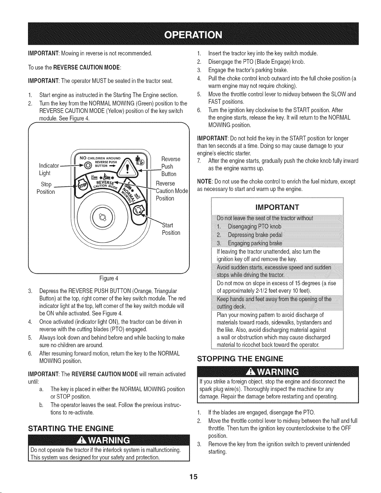
module.SeeFigure4.
N O CHILDREN AROUND
BUTTON
Light
Stop
Position
Reverse
Push
Button
Reverse
Mode
Position
Position
1, Insertthetractorkeyintothekeyswitchmodule,
2. DisengagethePTO(BladeEngage)knob.
3. Engagethetractor'sparkingbrake.
4. Pullthechokecontrolknoboutwardintothe fullchokeposition(a
warmenginemaynotrequirechoking).
5. MovethethrottlecontrollevertomidwaybetweentheSLOWand
FASTpositions.
6. Turnthe ignitionkeyclockwisetothe STARTposition.After
theenginestarts, releasethekey.Itwillreturntothe NORMAL
MOWINGposition.
IMPORTANT:Do notholdthekeyinthe STARTpositionfor longer
thantensecondsata time.Doingso maycausedamageto your
engine'selectricstarter.
7. Afterthe enginestarts,graduallypushthechokeknobfully inward
asthe enginewarmsup.
NOTE:Donotusethechokecontrolto enrichthefuel mixture,except
as necessarytostartandwarmuptheengine.
IMPORTANT
J
Figure4
3. DepresstheREVERSEPUSHBUTTON(Orange,Triangular
Button)atthe top,rightcornerofthekeyswitchmodule.Thered
indicatorlightatthe top,leftcornerofthe keyswitchmodulewill
beONwhileactivated.SeeFigure4.
4. Onceactivated(indicatorlightON),thetractorcanbedrivenin
reversewiththecuttingblades(PTO)engaged.
5. Alwayslookdownand behindbeforeandwhilebackingto make
surenochildrenarearound.
6. Afterresumingforwardmotion,returnthekeytothe NORMAL
MOWINGposition.
IMPORTANT:The REVERSECAUTIONMODEwill remainactivated
until:
a. Thekeyis placedin eitherthe NORMALMOWINGposition
orSTOPposition.
b. Theoperatorleavestheseat.Followthepreviousinstruc-
tionstore-activate.
STARTING THE ENGINE
wasdesic )rotection.
If leavingthetractorunattended,alsoturnthe
ignitionkeyoff and removethekey.
Donot mowon slopeinexcessof 15degrees(a rise
ofapproximately2-1/2feetevery10feet).
Planyourmowingpatternto avoiddischargeof
materialstowardroads,sidewalks,bystandersand
thelike.Also,avoiddischargingmaterialagainst
a wallor obstructionwhichmaycausedischarged
materialto ricochetbacktowardtheoperator.
STOPPING THE ENGINE
Ifyoustrikea foreignobject,stopthe engineanddisconnectthe
sparkplugwire(s).Thoroughlyinspectthemachineforany
damage.Repairthedamagebeforerestartingandoperating.
1. Ifthebladesareengaged,disengagethePTO.
2. Movethethrottlecontrollevertomidwaybetweenthehalfandfull
throttle.Thenturn theignitionkeycounterclockwisetotheOFF
position.
3. Removethe keyfromtheignitionswitchtopreventunintended
starting.
15
Page 16
DRiViNG THE TRACTOR
iMPORTANT:Avoidsuddenstarts,excessivespeedandsudden
stops.
NOTE:YourRevolutiontractorisequippedwithan innovativedrive
system.Itis normalforsomeforwardmovementofthetractortooccur
whenthe brakeis released.
.
Brieflydepressthebrakepedalto releasethe parkingbrake.
MovethethrottleleverintotheFAST(rabbit)position.
2.
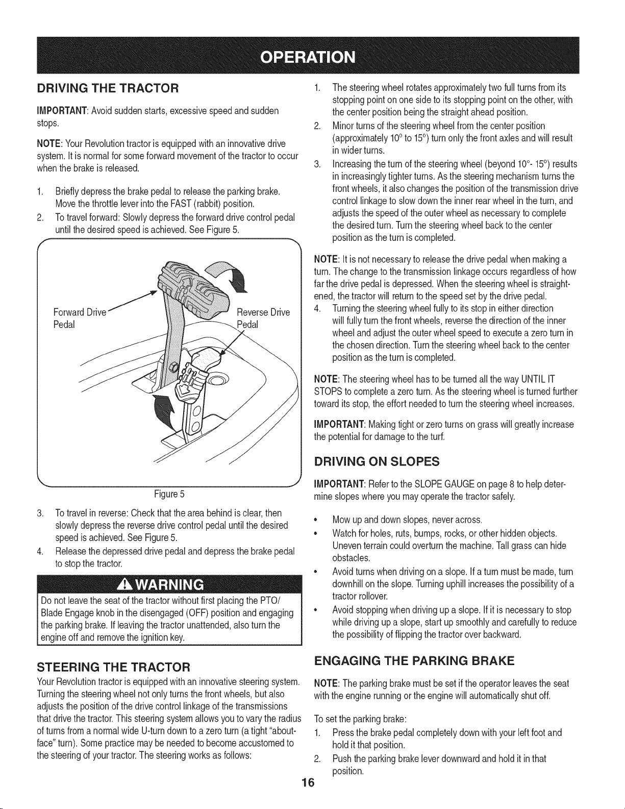
Totravelforward:Slowlydepresstheforwarddrivecontrolpedal
untilthe desiredspeedisachieved.SeeFigure5.
ForwardDrivef
Pedal
1. The steeringwheel rotatesapproximatelytwofullturnsfromits
stoppingpointonone sidetoitsstoppingpointonthe other,with
thecenterpositionbeingthe straightaheadposition.
2. Minorturnsof thesteeringwheelfromthe centerposition
(approximately100to 150) turnonly thefrontaxlesandwillresult
in widerturns.
3. Increasingtheturnofthesteeringwheel(beyond100.150) results
in increasinglytighterturns.Asthesteeringmechanismturnsthe
frontwheels,it alsochangesthepositionofthetransmissiondrive
controllinkagetoslowdowntheinnerrearwheelin theturn,and
adjuststhe speedof theouterwheelasnecessaryto complete
thedesiredturn.Turnthesteeringwheelbacktothe center
positionasthe turniscompleted.
NOTE:Itisnotnecessaryto releasethedrivepedalwhenmakinga
turn.Thechangetothetransmissionlinkageoccursregardlessofhow
farthe drivepedalisdepressed.Whenthesteeringwheelis straight-
ened,the tractorwill returntothespeedsetby thedrivepedal.
4. Turningthesteeringwheelfullytoits stopineitherdirection
willfullyturnthefrontwheels,reversethedirectionoftheinner
wheelandadjusttheouterwheelspeedtoexecutea zeroturn in
thechosendirection.Turnthe steeringwheelbackto thecenter
positionasthe turniscompleted.
NOTE:The steeringwheelhasto beturnedallthewayUNTILIT
STOPStocompleteazeroturn.Asthesteeringwheelisturnedfurther
towardits stop,theeffortneededtoturnthesteeringwheelincreases.
Figure5
3. Totravelin reverse:Checkthattheareabehindisclear,then
slowlydepressthe reversedrivecontrolpedaluntilthe desired
speedis achieved.SeeFigure5.
4. Releasethedepresseddrivepedalanddepressthebrakepedal
tostopthetractor.
Donotleavetheseatof thetractorwithoutfirstplacingthePTO/
BladeEngageknobin thedisengaged(OFF)positionandengaging
theparkingbrake.If leavingthetractorunattended,alsoturnthe
_engne offand removethe gnton key.
STEERING THE TRACTOR
YourRevolutiontractorisequippedwithan innovativesteeringsystem.
Turningthe steeringwheelnotonlyturnsthefrontwheels,butalso
adjuststhepositionofthe drivecontrollinkageofthetransmissions
thatdrivethe tractor.Thissteeringsystemallowsyouto varythe radius
ofturnsfromanormalwideU-turndowntoa zeroturn (a tight"about-
face"turn).Somepracticemaybe neededtobecomeaccustomedto
thesteeringofyourtractor.Thesteeringworksasfollows:
IMPORTANT:Makingtightor zeroturnsongrasswill greatlyincrease
thepotentialfordamageto theturf.
DRIVING ON SLOPES
IMPORTANT:Referto theSLOPEGAUGEonpage8 to helpdeter-
mineslopeswhereyoumayoperatethe tractorsafely.
• Mowupanddownslopes,neveracross.
• Watchforholes,ruts,bumps,rocks,orotherhiddenobjects.
Uneventerraincouldoverturnthemachine.Tallgrasscanhide
obstacles.
• Avoidturnswhendrivingon a slope,if a turnmustbemade,turn
downhillonthe slope.Turninguphillincreasesthe possibilityofa
tractorrollover.
• Avoidstoppingwhendrivingup a slope,if itis necessarytostop
whiledrivingupa slope,start upsmoothlyandcarefullyto reduce
thepossibilityof flippingthetractoroverbackward.
ENGAGING THE PARKING BRAKE
NOTE:The parkingbrakemustbe setiftheoperatorleavestheseat
withtheenginerunningor theenginewill automaticallyshutoff.
Tosettheparkingbrake:
1. Pressthe brakepedalcompletelydownwithyourIdt footand
holdit thatposition.
2. Pushtheparkingbrakeleverdownwardandholdit in that
position.
16
Page 17
3. Removeyourfootfromthebrakepedal.
4. Releasepressurefromtheparkingbrakelever.
Aftercompletingstep3,thebrakepedalshouldremaininthe down
position.Ifit doesn't,the parkingbrakeis notengaged.Repeatsteps
1-4toengagethe parkingbrake.
Todisengagetheparkingbrake,lightlypressthe brakepedal.
Neverleavea runningmachineunattended.AlwaysdisengagePTO,
setparkingbrake,stopengineand removekeyto preventunintended
starting.
2. Shutengineoffand removethekey.
Doingsowillminimizethe possibilityofhavingyourlawn"browned"by
hotexhaustfromyourtractor'srunningengine.
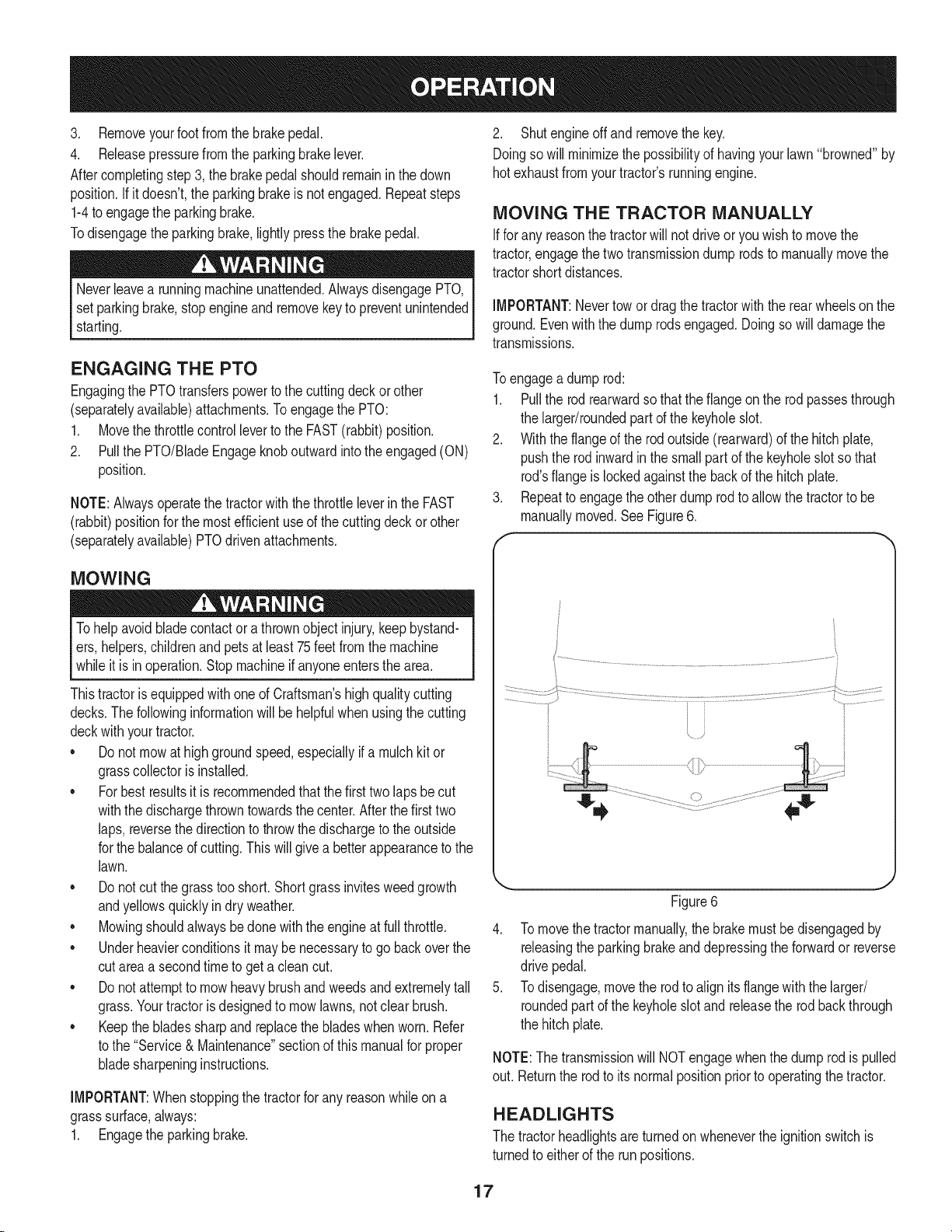
MOVING THE TRACTOR MANUALLY
Ifforanyreasonthetractorwillnot driveoryouwishtomovethe
tractor,engagethetwo transmissiondumprodstomanuallymovethe
tractorshortdistances.
IMPORTANT:Nevertowor dragthetractorwiththerearwheelsonthe
ground.Evenwiththedumprodsengaged.Doingsowill damagethe
transmissions.
ENGAGING THE PTO
EngagingthePTOtransferspowertothe cuttingdeckor other
(separatelyavailable)attachments.ToengagethePTO:
1. Movethe throttlecontrollevertotheFAST(rabbit)position.
2. PullthePTO/BladeEngageknoboutwardintothe engaged(ON)
position.
NOTE:Alwaysoperatethetractorwiththe throttleleverin theFAST
(rabbit)positionforthemostefficientuseofthe cuttingdeckorother
(separatelyavailable)PTOdrivenattachments.
MOWING
Tohelpavoidbladecontactor a thrownobjectinjury,keepbystand-
ers,helpers,childrenandpetsatleast75feetfromthemachine
whileit is inoperation.Stopmachineifanyoneentersthearea.
ThistractorisequippedwithoneofCraftsman'shighqualitycutting
decks.Thefollowinginformationwillbehelpfulwhenusingthecutting
deckwithyourtractor.
• Donot mowathighgroundspeed,especiallyif a mulchkitor
grasscollectoris installed.
• Forbestresultsitis recommendedthatthefirsttwolapsbecut
withthedischargethrowntowardsthecenter.Afterthefirsttwo
laps,reversethedirectiontothrowthe dischargeto theoutside
forthe balanceofcutting.Thiswillgivea betterappearancetothe
lawn.
• Donotcut thegrasstooshort.Shortgrassinvitesweedgrowth
andyellowsquicklyindryweather.
• Mowingshouldalwaysbedonewiththeengineat fullthrottle.
• Underheavierconditionsitmaybenecessaryto go backoverthe
cutareaa secondtimetogeta cleancut.
• Donotattempttomowheavybrushandweedsandextremelytall
grass.Yourtractorisdesignedto mowlawns,notclearbrush.
• Keepthebladessharpandreplacethebladeswhenworn.Refer
tothe "Service& Maintenance"sectionofthis manualforproper
bladesharpeninginstructions.
IMPORTANT:Whenstoppingthetractorfor anyreasonwhileona
grasssurface,always:
1. Engagethe parkingbrake.
Toengagea dump rod:
1. Pullthe rodrearwardso thattheflangeontherodpassesthrough
thelarge#roundedpartd thekeyholeslot.
2. Withtheflangeoftherodoutside(rearward)ofthe hitchplate,
pushthe rodinwardinthesmallpartofthe keyholeslotso that
rod'sflangeis lockedagainstthebackofthe hitchplate.
.
Repeattoengagetheotherdumprodto allowthetractortobe
manuallymoved.SeeFigure6.
f
...............................f_J
Figure6
4. Tomovethetractormanually,thebrakemustbedisengagedby
releasingthe parkingbrakeanddepressingthe forwardor reverse
drivepedal.
5. Todisengage,movetherodtoalign itsflangewiththe larger/
roundedpartd the keyholeslotand releasetherodbackthrough
thehitchplate.
NOTE:Thetransmissionwill NOTengagewhenthedump rodispulled
out. Returnthe rodto itsnormalpositionpriorto operatingthetractor.
HEADLIGHTS
Thetractorheadlightsare turnedonwheneverthe ignitionswitchis
turnedto eitherof therunpositions.
17
Page 18
MAINTENANCE SCHEDULE
Beforeperforminganytypeofmaintenance/service,disengageall
controlsandstoptheengine.Waituntilallmovingpartshavecometo
acompletestop.Disconnectsparkplugwireandgrounditagainstthe
enginetopreventunintendedstarting.Alwayswearsafetyglassesduring
operationor whileperforminganyadjustmentsor repairs.
BeforeEachUse
Inthe FirstFiveHours
Every10Hours
1. Engineoil level
2. Mufflerareaandcontrols
3. Fingerguard
1. EngineOil
1. Hood/Dashairvents
2. Batteryterminals
3. Deckspindlesandidler
1. Check
2. Clean
3. Clean
1. Change
1. Clean
2. Clean
3. Lubricate
bracket
Every25 hours
1. Air filter'sprecleaner*
2. Air filter*
3. Midsteeringarms,pivot
1. Clean
2. Clean
3. Lubricate
shafts,andaxles
4. Lubricate
5. Lubricate
1. Change/Replace
2. Check
1. Replace
2. Replace
3. Replace
4. Clean
5. Replace
1. Clean
2. Clean
3. Lubricate
Every50 hours
Annually
BeforeStorage
4. Frontwheelbearings
5. Frontdeckwheels
1. Engineoil/Oil filter
2. Muffler
1. Air filter
2. Air filter'spre-cleaner
3. Sparkplug
4. Air coolingsystem*
5. Fuelfilter
1. Hood/Dashairvents
2. Batteryterminals
3. Midsteeringarms,pivot
shafts,andaxles
4. Frontwheelbearings
5. Frontdeckwheels
6. Deckspindlesandidler
4. Lubricate
5. Lubricate
6. Lubricate
bracket
7. Pedalpivotpoints
7. Lubricate
*Servicemorefrequentlyunderdustyconditions.
Followthemaintenanceschedulegivenbelow.Thischartdescribes
serviceguidelinesonly.UsetheServiceLogcolumntokeeptrackof
completedmaintenancetasks.Tolocatethe nearest Sears Service
Centeror toscheduleservice,simplycontactSearsat
1-800-4-MY-HOME®.
Beforeperformingany maintenanceor repairs,disengagethePTO,
engagetheparkingbrake,stoptheengineandremovethekeyto
3reventunintendedstarting.
Iftheenginehasbeen recentlyrun,theengine,mufflerandsur-
roundingmetalsurfaceswillbehotand cancauseburnsto theskin.
Exercisecautionto avoidburns.
18
Page 19
ENGINE MAINTENANCE
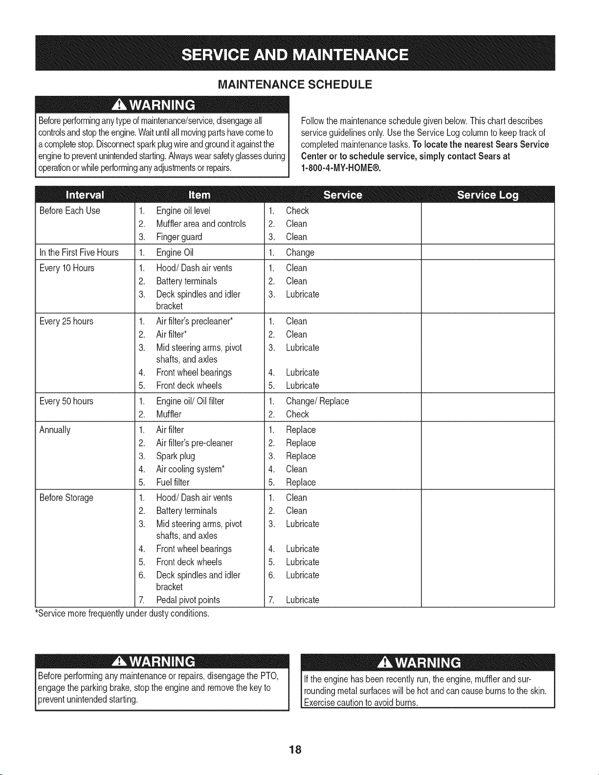
Checking the Engine Oil
Onlyuse highqualitydetergentoil ratedwithAPIserviceclassification
SF,SG,SH,or SJ, Selecttheoil'sSAEviscositygradeaccordingto
theexpectedoperatingtemperature.Followthechartbelow.
f_older _ 32°F _Warmer _
Oil Viscosity Chart
Althoughmulti-viscosityoils (5W20,10W30,etc.)improvestarting
in coldweather,theywill resultinincreasedoil consumptionwhen
usedabove32°RCheckyourengineoillevelmorefrequentlytoavoid
possibleenginedamagefromrunninglowonoil.
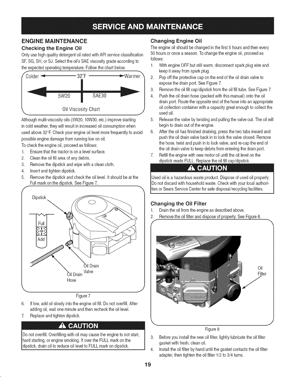
Tochecktheengineoil,proceedasfollows:
1. Ensurethatthetractorisona levelsurface.
2. Cleantheoil fillareaofanydebris.
3. Removethedipstickandwipewithacleancloth.
4. Insertandtightendipstick.
5. Removethedipstickandcheckthe oil level.It shouldbeatthe
Fullmarkonthedipstick.SeeFigure7.
F
Dipstick
Changing Engine Oil
Theengineoil shouldbechangedinthefirst5 hoursandthenevery
50 hoursoroncea season.Tochangetheengineoil, proceedas
follows:
1. WithengineOFFbut stillwarm,disconnectsparkplugwireand
keepit awayfromsparkplug.
2. Popoff theprotectivecapon theendoftheoil drainvalveto
exposethedrainport.SeeFigure7.
3. Removethe oilfillcap/dipstickfromtheoil fill tube.SeeFigure7.
4. Pushtheoil drainhose(packedwiththis manual)ontotheoil
drainport. Routethe oppositeendofthehoseintoan appropriate
oil collectioncontainerwithacapacitygreatenoughtocollectthe
usedoil.
5. Releasethevalvebytwistingandpullingthe valveout.Theoilwill
begintodrainoutoftheengine.
6. Aftertheoil hasfinisheddraining,pressthetwotabsinwardand
pushtheoil drainvalvebackinto lockthevalveclosed.Remove
thehose,twist andpushinto lockvalve,and re-captheendof
theoil drainvalvetokeepdebrisfromenteringthe drainport.
7. Refilltheenginewithnewmotoroil untiltheoil levelonthe
dipstickreadsFULL.Replacetheoil fillcap/dipstick.
Usedoil isahazardouswasteproduct.Disposeofusedoil properly.
IDonotdiscardwithhouseholdwaste.Checkwithyourlocal authori-
[tiesor SearsServiceCenterforsafedisposal/recyclingfacilities.
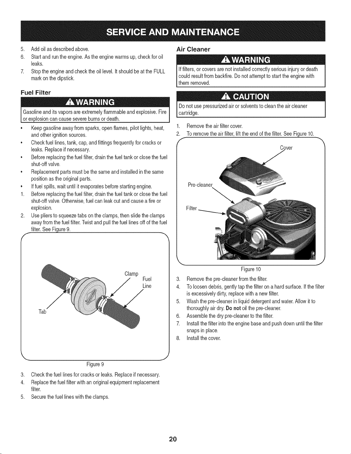
Changing the Oil Filter
1. Draintheoil fromtheengineasdescribedabove.
2. Removetheoilfilteranddis ure8.
OilDrain
Valve
il Drain
Hose
Figure7
6. If low,addoil slowlyintotheengineoilfill. Donotoverfill.After
addingoil,waitoneminuteand thenrechecktheoillevel.
7. Replaceandtightendipstick.
Donotoverfill.Overfillingwithoil maycausetheengineto notstart,
hardstarting,orenginesmoking.If overtheFULLmarkonthe
dipstick,drainoil to reduceoilleveltoFULLmarkondipstick.
Oil
Filter
Figure8
3. Beforeyouinstallthenewoilfilter,lightlylubricatetheoilfilter
gasketwithfresh,cleanoil.
4. Installtheoil filterbyhanduntilthe gasketcontactstheoil filter
adapter,thentightentheoilfilter 1/2to3/4 turns.
19
Page 20
5. Addoilasdescribedabove.
6. Startandruntheengine.Astheenginewarmsup,checkforoil
leaks.
7. Stoptheengineandchecktheoillevel.ItshouldbeattheFULL
markonthedipstick.
Fuel Filter
3losioncan causesevereburnsor death.
Keepgasolineawayfromsparks,openflames,pilotlights,heat,
andotherignitionsources.
Checkfuellines,tank,cap,andfittingsfrequentlyforcracksor
leaks.Replaceif necessary.
Beforereplacingthefuelfilter,drainthefueltankor closethe fuel
shut-offvalve.
Replacementpartsmustbethesameand installedinthe same
positionastheoriginalparts.
o
Iffuelspills,waituntilitevaporatesbeforestartingengine.
1.
Beforereplacingthefuelfilter,drainthefueltankor closethe fuel
shut-offvalve.Otherwise,fuel canleakoutandcauseafireor
explosion.
.
Usepliersto squeezetabsonthe clamps,thenslidetheclamps
awayfromthefuel filter.Twistand pullthefuellinesoff ofthefuel
filter.SeeFigure9.
f
Air Cleaner
Iffilters,or coversarenotinstalledcorrectlyseriousinjuryordeath
couldresultfrombackfire.Donotattemptto startthe enginewith
themremoved.
Donot usepressurizedair or solventstocleanthe aircleaner
cartridge.
.
Removethe airfiltercover.
2.
Toremovetheairfilter,lifttheendof thefilter.SeeFigure10.
f
Cover
Pre-cleaner
Filter
Clamp
Fuel
Line
Tab
Figure9
3. Checkthefuellinesforcracksorleaks.Replaceifnecessary.
4. Replacethefuelfilterwithan originalequipmentreplacement
filter.
5. Securethefuellineswiththeclamps.
Figure10
3. Removethe pre-cleanerfromthefilter.
4. Toloosendebris,gentlytapthe filteron a hardsurface.If thefilter
is excessivelydirty,replacewithanewfilter.
5. Washthepre-cleanerinliquiddetergentandwater.Allowit to
thoroughlyair dry.Do not oilthepre-cleaner.
6. Assemblethedrypre-cleanertothefilter.
7. Installthefilterintotheenginebaseand pushdownuntilthe filter
snapsin place.
8. Installthecover.
J
2O
Page 21
Spark Plug
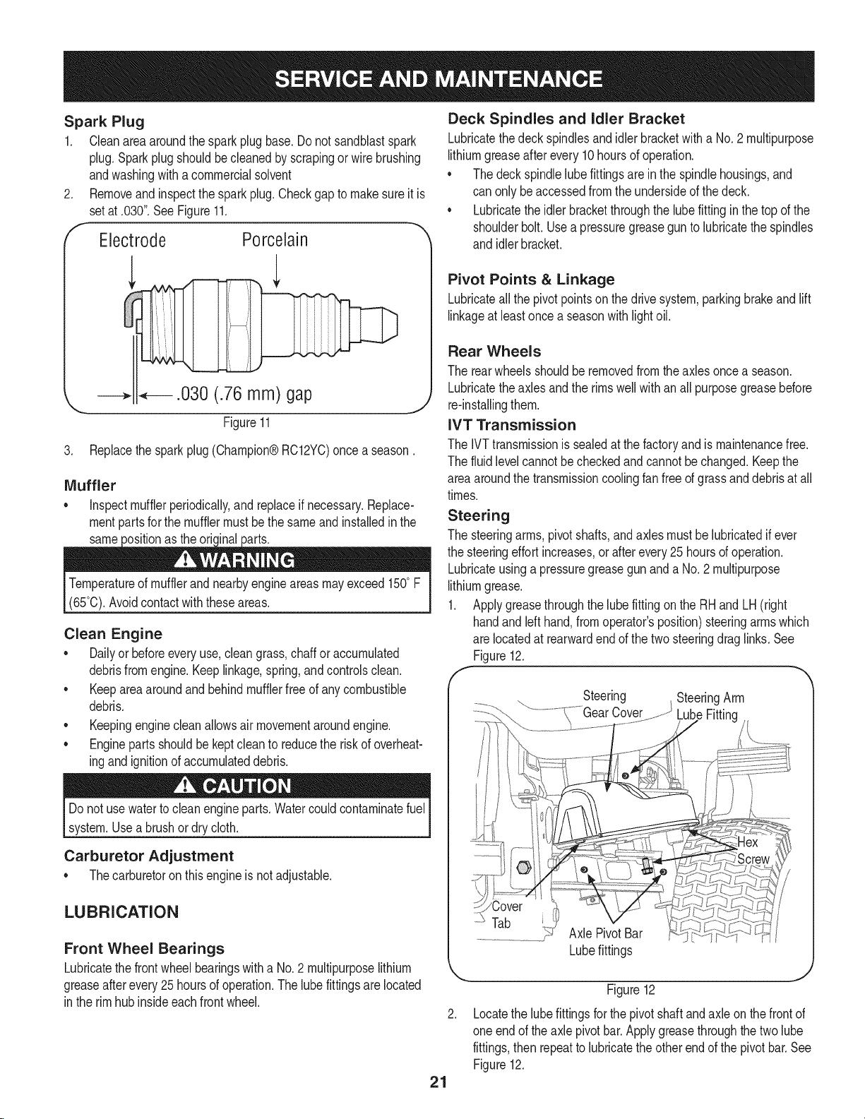
1. Cleanareaaroundthesparkplugbase.Donotsandblastspark
plug.Sparkplugshouldbecleanedby scrapingorwirebrushing
andwashingwitha commercialsolvent
2. Removeandinspectthesparkplug.Checkgaptomakesureit is
setat.030".SeeFigure11.
f- -._
Electrode Porcelain
3. Replacethesparkplug(Champion®RC12YC)oncea season.
Muffler
o inspectmufflerperiodically,and replaceifnecessary.Replace-
mentpartsforthemufflermustbethe sameand installedin the
same the oric
Temperatureof mufflerandnearbyengineareasmayexceed150°F
(65°0).Avoidcontactwiththeseareas.
Clean Engine
o Dailyor beforeeveryuse,cleangrass,chaff oraccumulated
debrisfromengine.Keeplinkage,spring,andcontrolsclean.
Keepareaaroundandbehindmufflerfreeofanycombustible
debris.
Keepingenginecleanallowsairmovementaroundengine.
• Enginepartsshouldbekeptcleanto reducetheriskofoverheat-
ingandignitionofaccumulateddebris.
Deck Spindles and Idler Bracket
Lubricatethedeckspindlesandidlerbracketwitha No.2 multipurpose
lithiumgreaseafterevery10hoursof operation.
• Thedeckspindlelubefittingsareinthe spindlehousings,and
canonly beaccessedfromthe undersideof thedeck.
• Lubricatetheidlerbracketthroughthelubefitting inthetopof the
shoulderbolt.Usea pressuregreaseguntolubricatethespindles
and idlerbracket.
Pivot Points & Linkage
Lubricateallthepivotpointsonthedrivesystem,parkingbrakeandlift
linkageatleastonceaseasonwithlightoil.
Rear Wheels
Therearwheelsshouldberemovedfromtheaxlesoncea season.
Lubricatetheaxlesandtherimswellwithan all purposegreasebefore
re-installingthem.
IVT Transmission
TheIVTtransmissionissealedatthefactoryandis maintenancefree.
Thefluidlevelcannotbecheckedandcannotbe changed.Keepthe
areaaroundthetransmissioncoolingfanfreeofgrassanddebrisatall
times.
Steering
Thesteeringarms,pivotshafts,andaxlesmustbelubricatedif ever
thesteeringeffortincreases,or afterevery25 hoursofoperation.
Lubricateusingapressuregreasegunanda No.2 multipurpose
lithiumgrease.
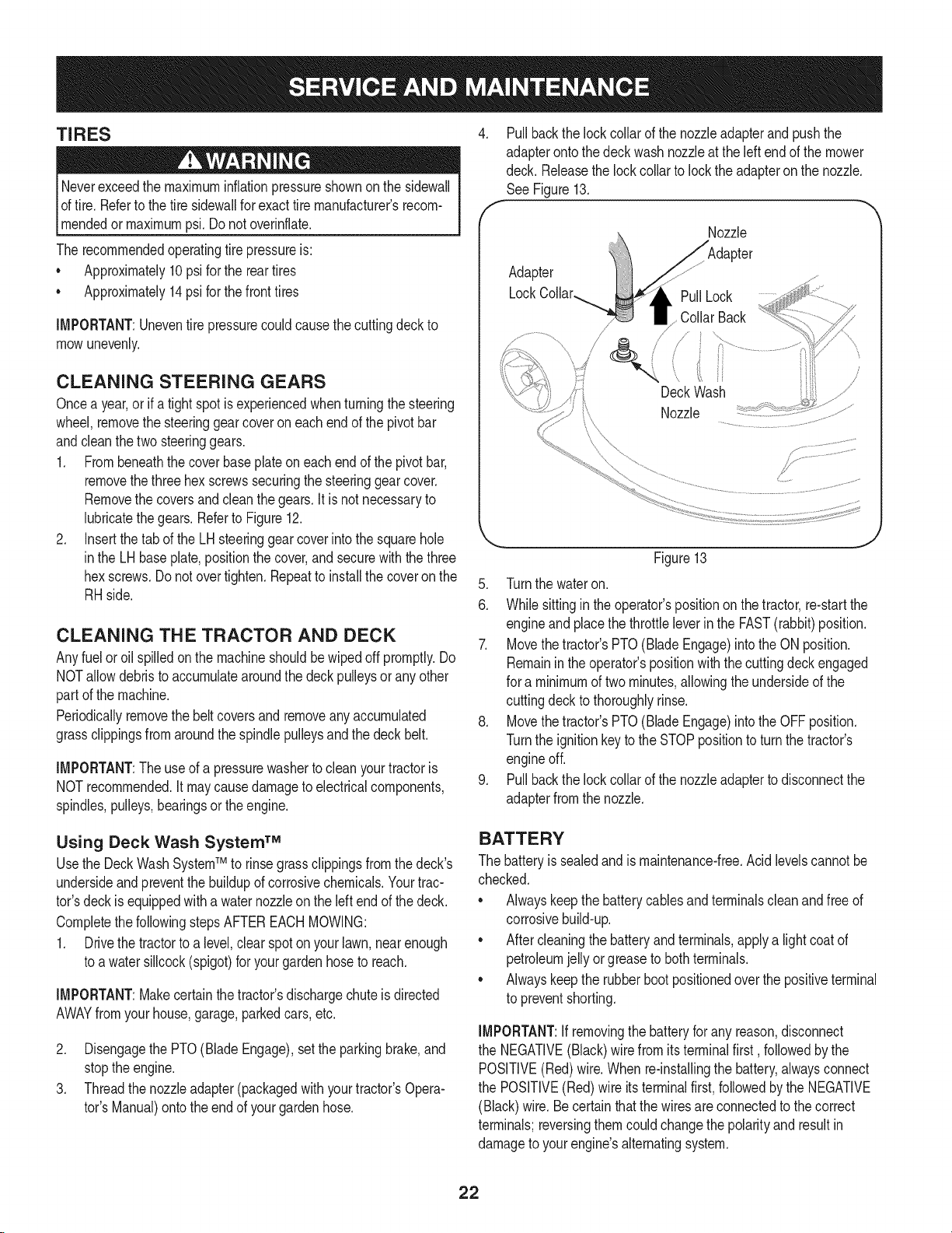
1. Applygreasethroughthelubefittingonthe RHandLH (right
handandleft hand,fromoperator'sposition)steeringarmswhich
are locatedat rearwardendofthetwo steeringdraglinks.See
Figure12.
f
Steering SteeringArm
LubeFitting
Donot usewatertocleanengineparts.Watercouldcontaminatefuel
system.Usea brushordrycloth.
Carburetor Adjustment
Thecarburetoronthisengineisnotadjustable.
LUBRICATION
Front Wheel Bearings
Lubricatethefrontwheelbearingswitha No.2 multipurposelithium
greaseafterevery25hoursofoperation.Thelubefittingsarelocated
in therimhubinsideeachfrontwheel.
Tab
AxlePivotBar
Lubefittings
Figure12
Locatethelubefittingsforthe pivotshaftandaxleonthe frontof
oneendof theaxle pivotbar.Applygreasethroughthe twolube
fittings,then repeattolubricatetheother endof thepivotbar.See
Figure12.
21
Page 22
TIRES
Neverexceedthe maximuminflationpressureshownont!e sidewall
oftire.Refertothetiresidewallforexacttire manufacturers recom-
_mendedor maxmumps. Donotovernfate.
Therecommendedoperatingtire pressureis:
• Approximately10psifor thereartires
Approximately14psifor thefronttires
IMPORTANT:Uneventire pressurecouldcausethe cuttingdeckto
mowunevenly.
CLEANING STEERING GEARS
Oncea year,or ifa tightspotisexperiencedwhenturningthe steering
wheel,removethesteeringgearcoveroneachendofthepivotbar
andcleanthe twosteeringgears.
1. Frombeneaththecoverbaseplateon eachendofthe pivotbar,
removethethreehexscrewssecuringthesteeringgearcover.
Removethe coversandcleanthegears.Itisnot necessaryto
lubricatethegears.RefertoFigure12.
2. Insertthe tabof theLHsteeringgearcoverintothesquarehole
inthe LHbaseplate,positionthecover,andsecurewiththethree
hexscrews.Donot overtighten.Repeatto installthecoveronthe
RHside.
CLEANING THE TRACTOR AND DECK
Anyfuel oroil spilledonthemachineshouldbewipedoff promptly.Do
NOTallowdebristoaccumulatearoundthedeckpulleysor anyother
partof themachine.
Periodicallyremovethe beltcoversandremoveany accumulated
grassclippingsfromaroundthespindlepulleysandthedeckbelt.
IMPORTANT:The useof a pressurewasherto cleanyourtractoris
NOTrecommended,itmaycausedamageto electricalcomponents,
spindles,pulleys,bearingsortheengine.
4. Pullbackthelockcollarofthenozzleadapterandpushthe
adapterontothedeckwashnozzleattheleftendofthemower
deck.Releasethelockcollartolockthe adapteronthenozzle.
See Figure13.
f
Nozzle
Adapter
PullLock
Collar Back
/
/
f,
Deck Wash
Nozzle
Figure13
5. Turnthe wateron.
6. Whilesittingin theoperator'spositionon the tractor,re-startthe
engineand placethethrottleleverintheFAST(rabbit)position.
7. Movethetractor'sPTO(BladeEngage)intotheON position.
Remainintheoperator'spositionwiththe cuttingdeckengaged
fora minimumoftwominutes,allowingtheundersideofthe
cuttingdeckto thoroughlyrinse.
8. Movethetractor'sPTO(BladeEngage)intotheOFFposition.
Turnthe ignitionkeytotheSTOPpositiontoturnthe tractor's
engineoff.
9. Pullbackthelockcollarofthenozzleadaptertodisconnectthe
adapterfromthe nozzle.
Using Deck Wash System TM
UsetheDeckWashSystemTM to rinsegrassclippingsfromthe deck's
undersideandpreventthebuildupofcorrosivechemicals.Yourtrac-
tor'sdeckis equippedwitha waternozzleonthe leftendof thedeck.
Completethe followingstepsAFTEREACHMOWING:
1. Drivethetractortoalevel,clearspotonyour lawn,nearenough
toa watersillcock(spigot)foryourgardenhoseto reach.
IMPORTANT:Makecertainthetractor'sdischargechuteisdirected
AWAYfromyourhouse,garage,parkedcars, etc.
2. DisengagethePTO(BladeEngage),settheparkingbrake,and
stoptheengine.
3. Threadthenozzleadapter(packagedwithyourtractor'sOpera-
tot'sManual)ontotheendof yourgardenhose.
BATTERY
Thebatteryissealedand ismaintenance-free.Acidlevelscannotbe
checked.
Alwayskeepthebatterycablesandterminalscleanandfreeof
corrosivebuild-up.
Aftercleaningthebatteryandterminals,applya lightcoatof
petroleumjellyorgreaseto bothterminals.
Alwayskeepthe rubberbootpositionedoverthepositiveterminal
to preventshorting.
IMPORTANT:If removingthe batteryforanyreason,disconnect
the NEGATIVE(Black)wirefromitsterminalfirst, followedby the
POSITIVE(Red)wire.Whenre-installingthebattery,alwaysconnect
the POSITIVE(Red)wire itsterminalfirst,followedbytheNEGATIVE
(Black)wire.Becertainthatthewiresareconnectedtothecorrect
terminals;reversingthemcouldchangethepolarityandresultin
damagetoyourengine'salternatingsystem.
22
Page 23
Charging the Battery
If thetractorhasnotbeenputintouse foranextendedperiodof
time,chargethe batterywithanautomotive-type12-voltchargerfora
minimumof onehourat sixamps.
Batteriesgiveoffan explosivegaswhilecharging.Chargebatteryin
awellventilatedareaandkeepawayfromanopenflameorpilot light
asonawaterheater,spaceheater,furnace,clothesdryerorother
gasappliances.
Cleaning the Battery
Cleanthe batterybyremovingitfromthetractorandwashingwith
a bakingsodaandwatersolution.Ifnecessary,scrapethebattery
terminalswitha wirebrushtoremovedeposits.Coatterminalsand
exposedwiringwithgreaseorpetroleumjellytopreventcorrosion.
Battery Failures
Somecommoncausesforbatteryfailureare:
• Incorrectinitialactivation•undercharging
• Overcharging• corrodedconnections
• Freezing
ThesefailuresareNOTcoveredbyyourtractor'swarranty.
Seat
Afteradjustingtheseator beforedrivingthetractor,makesurethat
theseatadjustmentleveris engagedin the seatindexplateand
thattheseatwillnotmove.Donotadjustthe seatwhilethetractor
is beingdriven.Adjustingtheseatwhilethetractorismovingcould
causetheoperatorto losecontrolofthetractor.
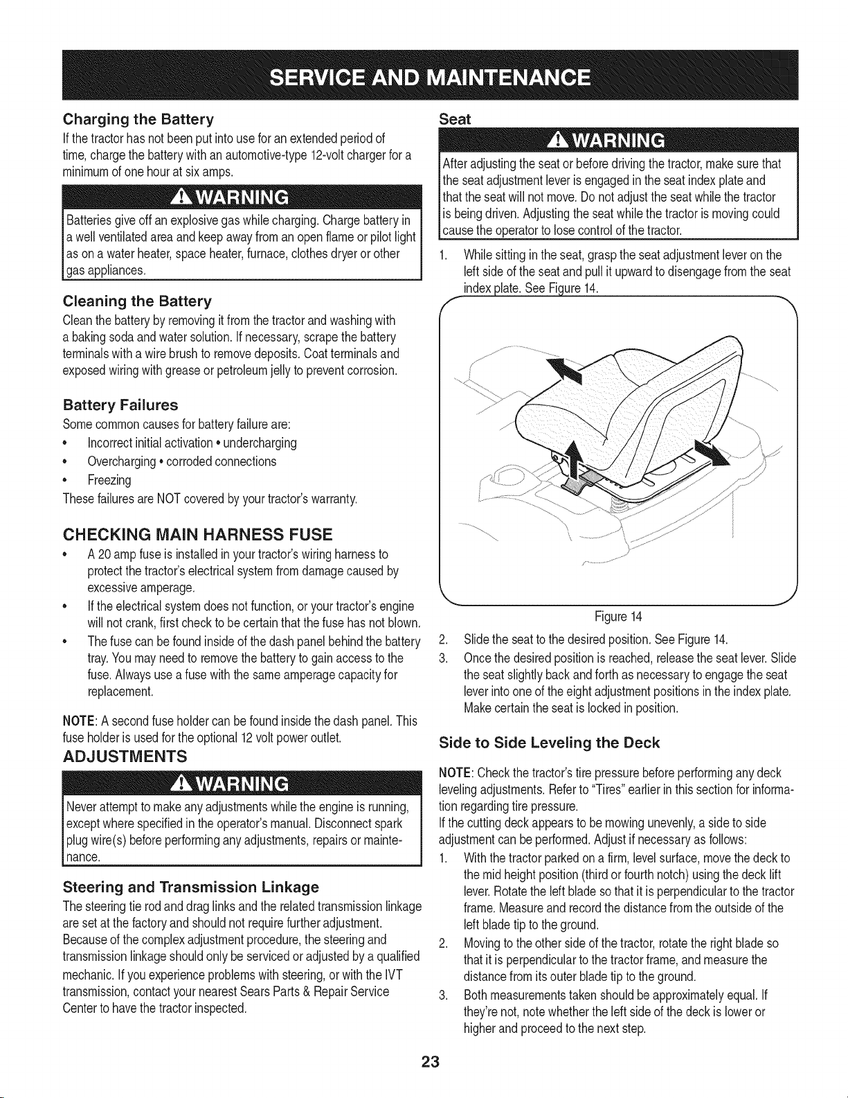
1. Whilesittingintheseat,graspthe seatadjustmentleveronthe
Idt sideofthe seatandpullit upwardtodisengagefromtheseat
indexplate.SeeFigure14.
f
CHECKING MAIN HARNESS FUSE
• A20ampfuseis installedin yourtractor'swiringharnessto
protectthetractor'selectricalsystemfromdamagecausedby
excessiveamperage.
• Iftheelectricalsystemdoesnotfunction,oryourtractor'sengine
willnotcrank,firstchecktobecertainthatthefuse hasnotblown.
• Thefusecan befoundinsideof thedashpanelbehindthebattery
tray.Youmayneedto removethebatterytogainaccesstothe
fuse.Alwaysusea fusewiththesameamperagecapacityfor
replacement.
NOTE:A secondfuseholdercanbe foundinsidethedash panel.This
fuseholderisusedfortheoptional12voltpoweroutlet.
ADJUSTMENTS
Neverattemptto makeanyadjustmentswhiletheengineis running,
exceptwherespecifiedintheoperator'smanual.Disconnectspark
plugwire(s)beforeperforminganyadjustments,repairsormainte-
nance.
Steering and Transmission Linkage
Thesteeringtie rodanddraglinksandthe relatedtransmissionlinkage
aresetatthefactoryandshouldnotrequirefurtheradjustment.
Becauseofthecomplexadjustmentprocedure,the steeringand
transmissionlinkageshouldonlybe servicedoradjustedbya qualified
mechanic.If youexperienceproblemswith steering,or withthe IVT
transmission,contactyournearestSearsParts& RepairService
Centertohavethetractorinspected.
Figure14
2. Slidetheseattothedesiredposition.SeeFigure14.
3. Oncethedesiredpositionis reached,releasetheseatlever.Slide
theseatslightlybackandforthasnecessaryto engagetheseat
leverintooneoftheeightadjustmentpositionsinthe indexplate.
Makecertaintheseatislockedin position.
Side to Side Leveling the Deck
NOTE:Checkthetractor'stirepressurebeforeperforminganydeck
levelingadjustments.Referto"Tires"earlierinthissectionfor informa-
tionregardingtirepressure.
Ifthecuttingdeckappearstobe mowingunevenly,a sideto side
adjustmentcanbeperformed.Adjustif necessaryas follows:
1. Withthetractorparkedona firm, levelsurface,movethedeckto
themid heightposition(thirdorfourthnotch)usingthedecklift
lever.Rotatetheleft bladeso thatit isperpendiculartothetractor
frame.Measureandrecordthedistancefromtheoutsideofthe
leftbladetiptotheground.
2. Movingtotheothersideofthetractor,rotatetheright bladeso
thatit isperpendiculartothetractorframe,andmeasurethe
distancefromits outerbladetipto theground.
3. Bothmeasurementstakenshouldbeapproximatelyequal.If
they'renot,notewhethertheleftside ofthedeckis loweror
higherandproceedtothenextstep.
23
Page 24
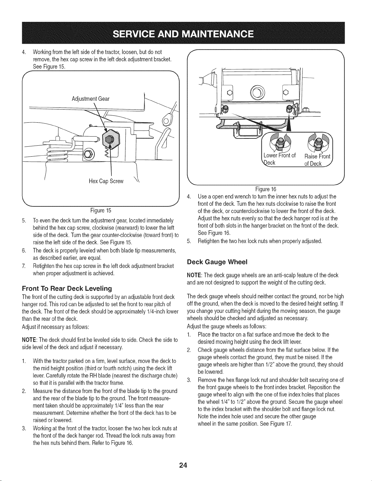
4. Workingfromtheleftsideof thetractor,loosen,butdonot
remove,the hexcapscrewin theleftdeckadjustmentbracket.
SeeFigure15.
AdjustmentGear
HexCapScrew
Figure15
5. Toeventhedeckturntheadjustmentgear,locatedimmediately
behindthehexcapscrew,clockwise(rearward)to lowertheleft
sideof thedeck.Turnthegearcounter-clockwise(towardfront)to
raisethe left sideofthedeck.SeeFigure15.
6. Thedeckis properlyleveledwhenbothbladetip measurements,
asdescribedearlier,areequal.
7. Retightenthe hexcap screwin theleftdeckadjustmentbracket
whenproperadjustmentisachieved.
Front To Rear Deck Leveling
Thefrontof thecuttingdeckissupportedbyanadjustablefrontdeck
hangerrod.This rodcanbeadjustedtosetthefrontto rearpitchof
thedeck. Thefrontofthedeckshouldbeapproximately1/4-inchlower
thanthe rearofthedeck.
Adjustifnecessaryasfollows:
NOTE:Thedeckshouldfirstbeleveledsideto side.Checkthesideto
sidelevelofthedeckandadjustif necessary.
1. Withthetractorparkedonafirm,levelsurface,movethedeckto
themidheightposition(thirdor fourthnotch)usingthedeck lift
lever.Carefullyrotatethe RHblade(nearestthedischargechute)
sothatitis parallelwiththe tractorframe.
2. Measurethedistancefromthefrontof thebladetiptotheground
andtherearofthebladetipto theground.The frontmeasure-
menttakenshouldbeapproximately1/4"lessthanthe rear
measurement.Determinewhetherthefrontofthe deckhasto be
raisedorlowered.
3. Workingatthefrontof thetractor,loosenthe twohexlocknutsat
thefrontof thedeckhangerrod.Threadthelocknutsawayfrom
thehexnutsbehindthem.Referto Figure16.
f
)eck ofDeck
Figure16
4. Usea openendwrenchtoturntheinnerhexnutsto adjustthe
frontofthedeck.Turnthehexnutsclockwisetoraisethefront
ofthe deck,orcounterclockwiseto lowerthefrontofthe deck.
Adjustthe hexnutsevenlysothatthedeckhangerrod isat the
frontofbothslotsinthe hangerbracketon the frontofthe deck.
See Figure16.
5. Refightenthe twohexlocknutswhenproperlyadjusted.
Deck Gauge Wheel
NOTE:The deckgaugewheelsareananti-scalpfeatureofthe deck
andare notdesignedto supporttheweightofthecuttingdeck.
Thedeckgaugewheelsshouldneithercontacttheground,norbehigh
off theground,whenthedeckismovedtothedesiredheightsetting.If
youchangeyourcuttingheightduringthe mowingseason,thegauge
wheelsshouldbecheckedandadjustedas necessary.
Adjustthegaugewheelsasfollows:
1. Placethetractorona fiatsurfaceandmovethe decktothe
desiredmowingheightusingthe decklift lever.
2. Checkgaugewheelsdistancefromtheflat surfacebelow.Ifthe
gaugewheelscontacttheground,theymustberaised.Ifthe
gaugewheelsare higherthan1/2"abovethe ground,theyshould
be lowered.
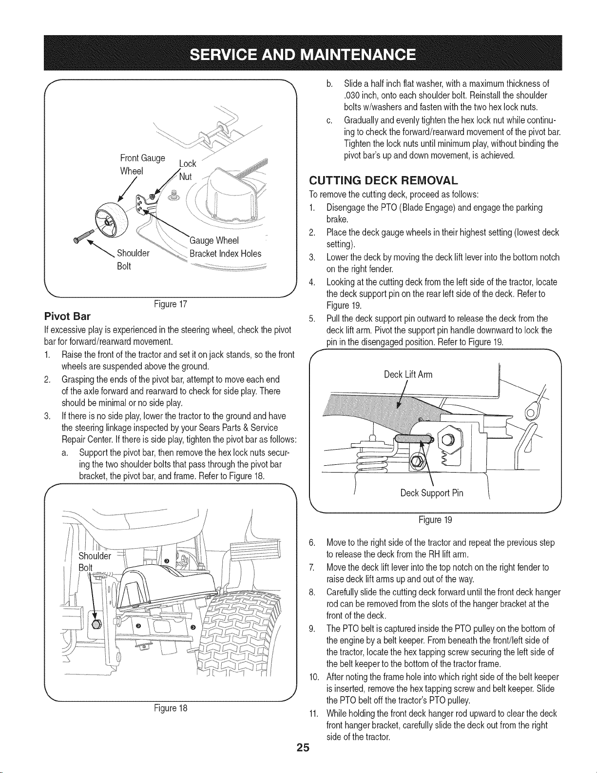
3. Removethe hexflangelocknutandshoulderboltsecuringoneof
thefrontgaugewheelstothefrontindexbracket.Repositionthe
gaugewheelto alignwiththeoneoffiveindexholesthatplaces
thewheel 1/4"to 1/2"abovetheground.Securethegaugewheel
tothe indexbracketwiththe shoulderboltandflangelocknut.
Notetheindexholeusedandsecuretheothergauge
wheelin the sameposition.SeeFigure17.
24
Page 25
f
FrontGauge Lock ............
Wheel
Wheel
Shoulder BracketIndexHoles
Bolt
'_. j
Figure17
Pivot Bar
If excessiveplay isexperiencedin thesteeringwheel,checkthe pivot
barforforward/rearwardmovement.
1. Raisethe frontofthetractorand setitonjackstands,sothefront
wheelsaresuspendedabovetheground.
2. Graspingtheendsof thepivotbar,attempttomoveeachend
ofthe axleforwardandrearwardtocheckfor sideplay.There
shouldbeminimalornosideplay.
3. If thereis no sideplay,lowerthetractortothegroundandhave
thesteeringlinkageinspectedbyyourSearsParts& Service
RepairCenter.Ifthereis sideplay,tightenthepivotbarasfollows:
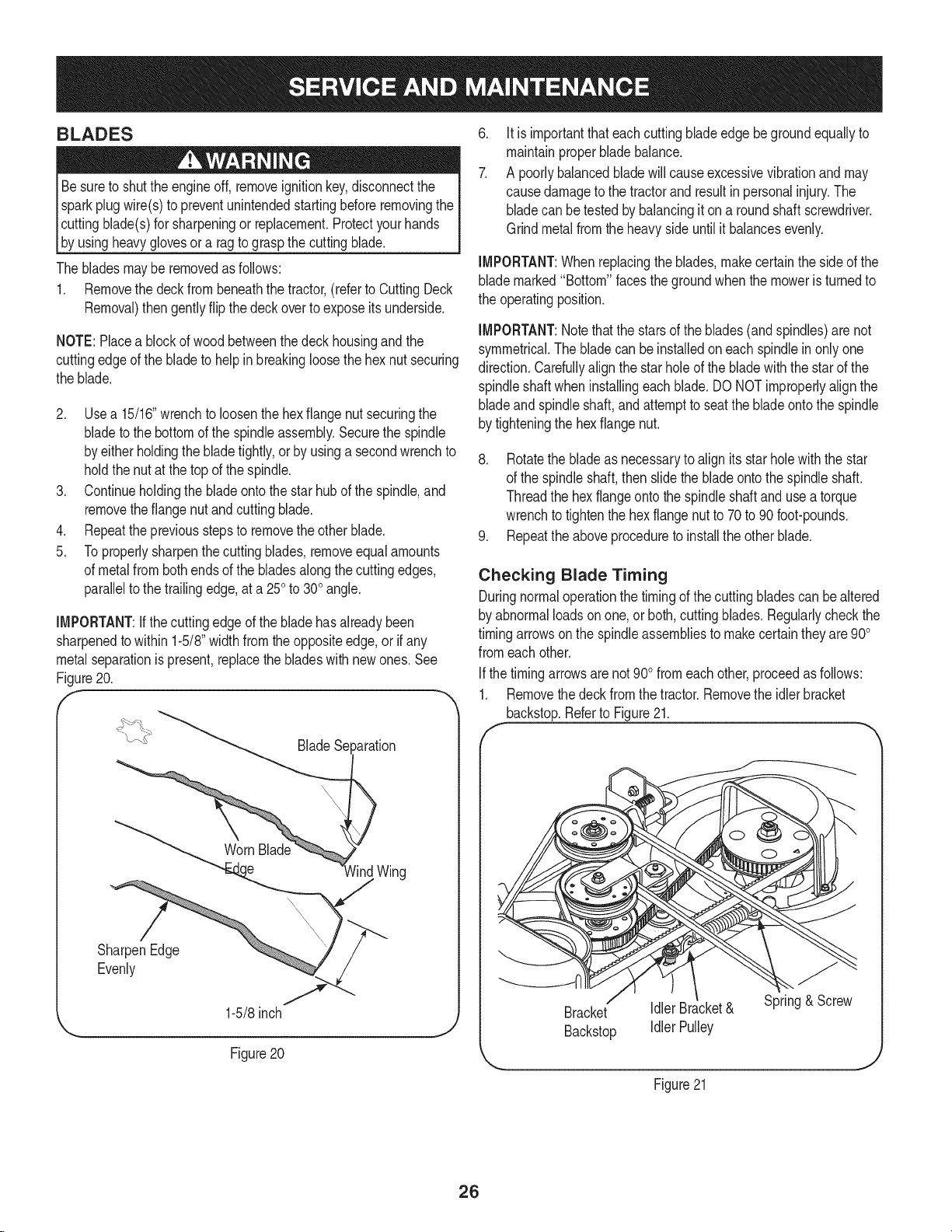
a. Supportthepivotbar,thenremovethehexlocknutssecur-
ingthetwoshoulderboltsthatpassthroughthe pivotbar
bracket,thepivotbar,andframe.RefertoFigure18.
b. Slidea halfinchflatwasher,witha maximumthicknessof
.030inch,onto eachshoulderbolt.Reinstalltheshoulder
boltsw/washersandfastenwiththetwohexlock nuts.
c. Graduallyandevenlytightenthehexlocknut whilecontinu-
ingtochecktheforward/rearwardmovementofthe pivotbar.
Tightenthelocknutsuntilminimumplay,withoutbindingthe
pivotbar'supanddownmovement,isachieved.
CUTTING DECK REMOVAL
Toremovethecuttingdeck,proceedasfollows:
1. DisengagethePTO(BladeEngage)andengagethe parking
brake.
2. Placethedeckgaugewheelsin theirhighestsetting(lowestdeck
setting).
3. Lowerthedeck bymovingthe decklift leverintothe bottomnotch
on therightfender.
4. Lookingatthecuttingdeckfromtheleftsideof thetractor,locate
thedecksupportpinontherearleftside ofthedeck.Referto
Figure19.
5. Pullthedecksupportpinoutwardtoreleasethedeckfromthe
decklift arm.Pivotthesupportpinhandledownwardto lockthe
pininthedisengagedposition.RefertoFigure19.
DeckLiftArm
Figure18
DeckSupportPin
Figure19
6. Moveto therightsideofthe tractorandrepeatthe previousstep
to releasethedeckfromtheRHlift arm.
7. Movethedecklift leverintothetopnotchon therightfenderto
raisedeckliftarmsupandoutof theway.
8. Carefullyslidethecuttingdeckforwarduntilthefrontdeckhanger
rodcanbe removedfromthe slotsof thehangerbracketat the
frontofthedeck.
9. ThePTObeltiscapturedinsidethePTOpulleyonthebottomof
theengineby a beltkeeper.Frombeneaththefront/leftsideof
thetractor,locatethe hextappingscrewsecuringtheleftsideof
thebelt keepertothebottomofthetractorframe.
10. Afternotingtheframeholeintowhichrightsideofthebelt keeper
isinserted,removethehextappingscrewandbelt keeper.Slide
thePTObeltoffthetractor'sPTOpulley.
11. Whileholdingthe frontdeckhangerrodupwardtoclearthedeck
fronthangerbracket,carefullyslidethedeckout fromtheright
sideof thetractor.
25
Page 26
BLADES
Besureto shutthe engineoff,removeignitionkey,disconnectthe
sparkplugwire(s)topreventunintendedstartingbeforeremovingthe
cuttingblade(s)forsharpeningor replacement.Protectyourhands
b_ usng heavygovesor a ragtograspthecuttng bade.
Thebladesmayberemovedas follows:
1. Removethe deckfrombeneaththetractor,(referto CuttingDeck
Removal)then gentlyflipthedeckoverto exposeitsunderside.
NOTE:Placea blockofwoodbetweenthedeck housingandthe
cuttingedgeof the bladeto helpin breakingloosethehexnut securing
theblade.
2. Usea 15/16"wrenchtoloosenthehexflangenutsecuringthe
bladetothe bottomof thespindleassembly.Securethespindle
byeitherholdingthebladetightly,orbyusinga secondwrenchto
holdthenutatthetopofthe spindle.
3. Continueholdingthebladeontothestarhubofthespindle,and
removetheflangenutandcuttingblade.
4. Repeatthepreviousstepstoremovetheotherblade.
5. Toproperlysharpenthecuttingblades,removeequalamounts
ofmetalfrombothendsofthebladesalongthecuttingedges,
paralleltothe trailingedge,ata250to300angle.
iMPORTANT:ifthecuttingedgeofthebladehasalreadybeen
sharpenedto within1-5/8"widthfromtheoppositeedge,or ifany
metalseparationis present,replacethebladeswith newones.See
Figure20.
f
_aration
.
Itis importantthateach cuttingbladeedgebegroundequallyto
maintainproperbladebalance.
7.
A poorlybalancedbladewillcauseexcessivevibrationandmay
causedamageto thetractorand resultin personalinjury.The
bladecanbetestedbybalancingit ona roundshaftscrewdriver.
Grindmetalfromtheheavysideuntilit balancesevenly.
iMPORTANT:Whenreplacingtheblades,makecertainthesideofthe
blademarked"Bottom"facesthegroundwhenthemoweris turnedto
theoperatingposition.
iMPORTANT:Notethatthe starsoftheblades(andspindles)arenot
symmetrical.The bladecanbeinstalledoneachspindlein onlyone
direction.Carefullyalignthestarholeof thebladewiththe starofthe
spindleshaftwheninstallingeachblade.DO NOTimproperlyalignthe
bladeandspindleshaft,andattempttoseatthe bladeontothe spindle
bytighteningthehexflange nut.
8. Rotatethebladeasnecessarytoalignits starholewiththestar
ofthe spindleshaft,thenslidethebladeontothespindleshaft.
Threadthe hexflangeontothe spindleshaftandusea torque
wrenchtotightenthe hexflangenutto 70to 90foot-pounds.
9. Repeattheaboveproceduretoinstalltheotherblade.
Checking Blade Timing
Duringnormaloperationthetimingofthecuttingbladescan bealtered
byabnormalloadsonone,orboth,cuttingblades.Regularlycheckthe
timingarrowsonthespindleassembliestomakecertaintheyare900
fromeachother.
Ifthetimingarrowsarenot900fromeachother,proceedasfollows:
1. Removethe deckfromthetractor.Removetheidlerbracket
backstop.Referto Figure21.
f
SharpenEdge
Evenly
1-5/8inch
Figure20
)
lind Wing
Bracket IdlerBracket& Spring&Screw
Backstop IdlerPulley
Figure21
26
Page 27
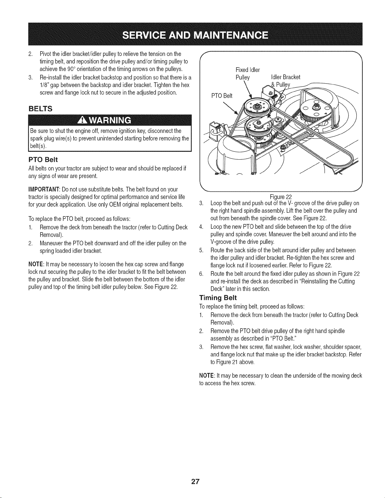
2. Pivottheidlerbracket/idlerpulleyto relievethetensiononthe
timingbelt,and repositionthedrivepulleyand/ortimingpulleyto
achievethe900orientationofthetimingarrowsonthe pulleys.
3. Re-installtheidlerbracketbackstopandpositionsothatthereisa
1/8"gapbetweenthebackstopandidlerbracket.Tightenthehex
screwandflange locknutto secureinthe adjustedposition.
BELTS
Besureto shuttheengineoff,removeignitionkey,disconnectthe
sparkplugwire(s)topreventunintendedstartingbeforeremovingthe
belt(s).
PTO Belt
Allbeltsonyourtractoraresubjecttowearandshouldbereplacedif
anysignsof weararepresent.
f
FixedIdler
Pulley IdlerBracket
PTOBelt
IMPORTANT:Do notusesubstitutebelts.Thebeltfoundonyour
tractoris speciallydesignedforoptimalperformanceandservicelife
foryourdeckapplication.UseonlyOEMoriginalreplacementbelts.
Toreplacethe PTObelt,proceedasfollows:
1. Removethedeckfrombeneaththe tractor(referto CuttingDeck
Removal).
2. ManeuverthePTObeltdownwardandofftheidlerpulleyonthe
springloadedidlerbracket.
NOTE:It maybe necessarytoloosenthehexcapscrewandflange
locknutsecuringthepulleytotheidlerbrackettofitthe beltbetween
thepulleyand bracket.Slidethe beltbetweenthe bottomoftheidler
pulleyandtop ofthetimingbeltidlerpulleybelow.SeeFigure22.
,,, j
Figure22
3. Loopthebeltand pushoutof theV-grooveofthedrivepulleyon
theright handspindleassembly.Liftthe beltoverthepulleyand
outfrombeneaththe spindlecover.SeeFigure22.
4. LoopthenewPTObeltandslidebetweenthetopofthedrive
pulleyandspindlecover.Maneuverthe beltaroundandintothe
V-grooveofthedrivepulley.
5. Routethebacksideof thebeltaroundidlerpulleyandbetween
theidlerpulleyandidlerbracket.Re-tightenthehexscrewand
flangelock nutifloosenedearlier.Referto Figure22.
6. Routethebelt aroundthefixedidlerpulleyas shownin Figure22
and re-installthedeckasdescribedin"ReinstallingtheCutting
Deck"laterinthis section.
Timing Belt
Toreplacethetimingbelt,proceedas follows:
1. Removethe deckfrombeneaththetractor(refertoCuttingDeck
Removal).
2. Removethe PTObeltdrivepulleyof the righthandspindle
assemblyasdescribedin"PTOBelt."
3. Removethe hexscrew,flatwasher,lockwasher,shoulderspacer,
andflangelocknutthatmakeup the idlerbracketbackstop.Refer
to Figure21above.
NOTE:Itmaybenecessaryto cleantheundersideofthemowingdeck
toaccessthehexscrew.
27
Page 28
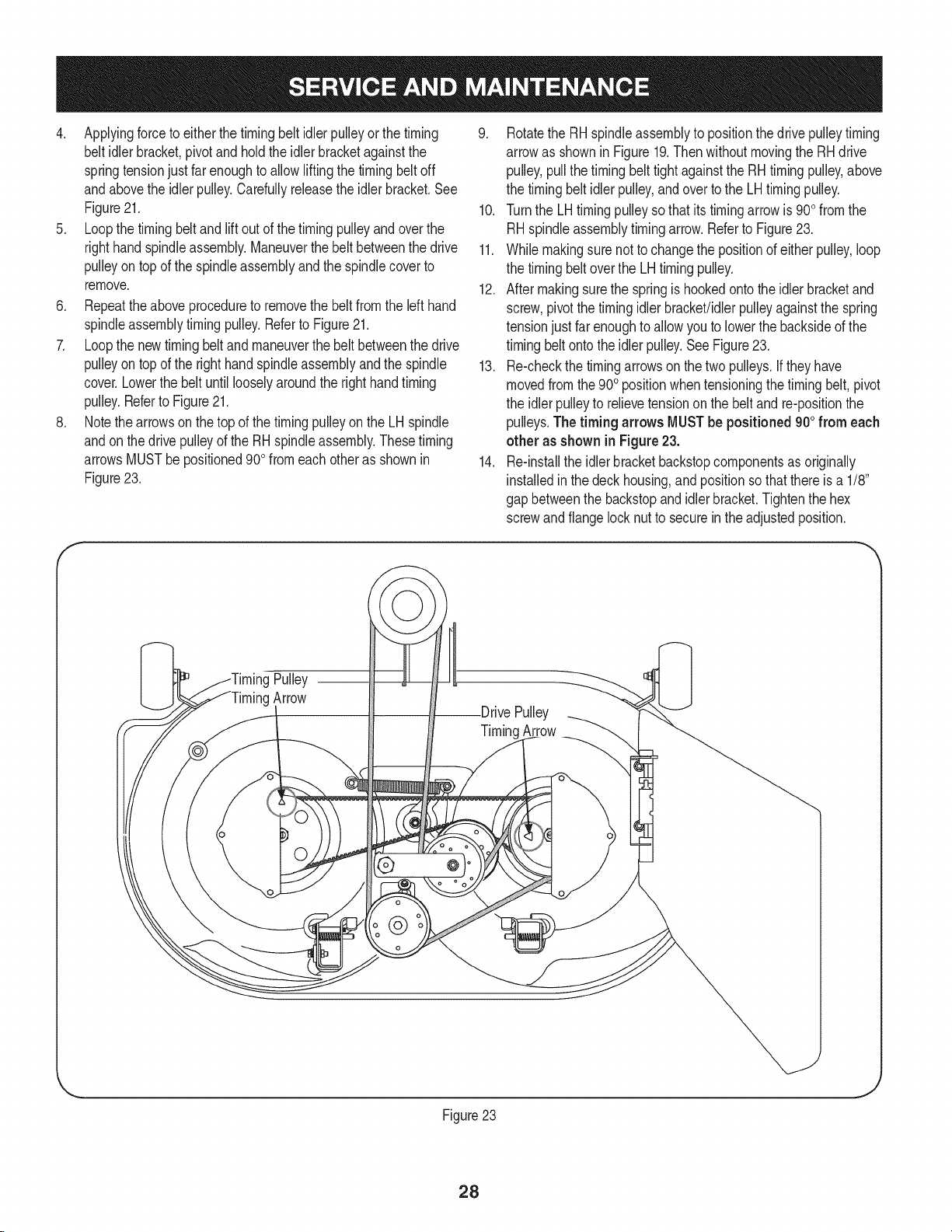
4. Applyingforceto eitherthetimingbeltidlerpulleyor thetiming
beltidlerbracket,pivotand holdtheidlerbracketagainstthe
springtensionjustfarenoughto allowliftingthe timingbeltoff
andabovetheidlerpulley.Carefullyreleasethe idlerbracket.See
Figure21.
5. Loopthetimingbeltandlift outofthe timingpulleyandoverthe
righthandspindleassembly.Maneuverthe beltbetweenthedrive
pulleyontop ofthespindleassemblyandthespindlecoverto
remove.
6. Repeattheaboveproceduretoremovethebeltfromthe left hand
spindleassemblytimingpulley.RefertoFigure21.
7. Loopthe newtimingbeltand maneuverthebelt betweenthedrive
pulleyontop oftherighthandspindleassemblyandthe spindle
cover.Lowerthebeltuntil looselyaroundtherighthandtiming
pulley.RefertoFigure21.
8. Notethearrowson thetopofthetimingpulleyonthe LHspindle
andonthedrivepulleyofthe RHspindleassembly.Thesetiming
arrowsMUSTbepositioned90ofromeachotherasshownin
Figure23.
9. RotatetheRHspindleassemblyto positionthedrivepulleytiming
arrowas shownin Figure19.Then withoutmovingtheRHdrive
pulley,pullthetimingbelttightagainsttheRHtimingpulley,above
thetimingbeltidlerpulley,andovertothe LHtimingpulley.
10. Turnthe LHtimingpulleysothat itstimingarrowis900fromthe
RHspindleassemblytimingarrow.RefertoFigure23.
11. Whilemakingsure nottochangethepositionofeitherpulley,loop
thetimingbeltovertheLHtimingpulley.
12. Aftermakingsurethespringishookedontotheidlerbracketand
screw,pivotthetimingidlerbracket!idlerpulleyagainstthespring
tensionjustfarenoughtoallowyouto lowerthebacksideofthe
timingbeltonto theidlerpulley.SeeFigure23.
13. Re-checkthetimingarrowsonthetwopulleys.Iftheyhave
movedfromthe900positionwhentensioningthetimingbelt,pivot
theidlerpulleytorelievetensiononthe beltand re-positionthe
pulleys.Thetiming arrows MUSTbe positioned900from each
other as shownin Figure23.
14. Re-installthe idlerbracketbackstopcomponentsasoriginally
installedin thedeck housing,andpositionsothatthereis a 1/8"
gap betweenthebackstopandidlerbracket.Tightenthehex
screwandflangelocknuttosecurein theadjustedposition.
Pulley
Arrow
Pulley
TimingArrow
@
Figure23
28
Page 29
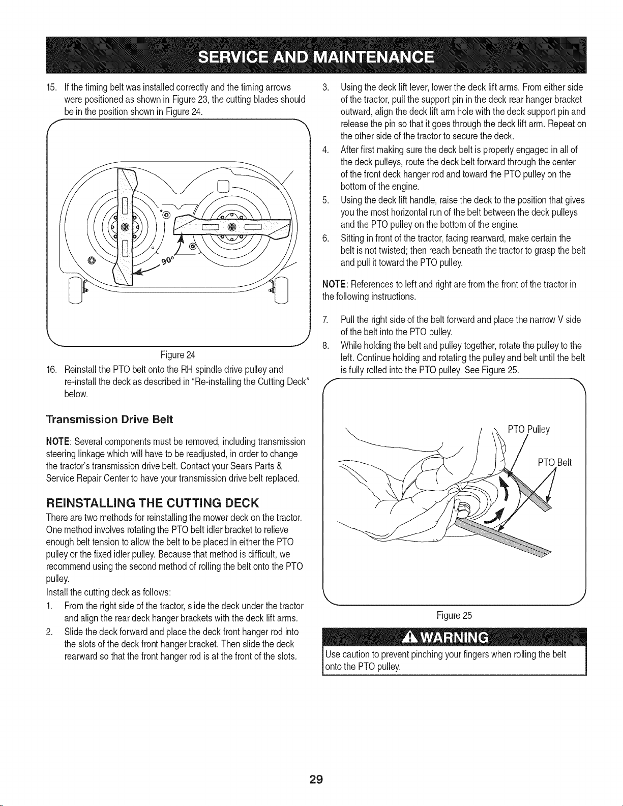
15. If thetimingbeltwasinstalledcorrectlyandthetimingarrows
werepositionedasshownin Figure23,thecuttingbladesshould
bein thepositionshowninFigure24.
-.. J
Figure24
16. ReinstallthePTObeltontothe RHspindledrivepulleyand
re-installthedeckasdescribedin"Re-installingtheCuttingDeck"
below.
3. Usingthedecklift lever,lowerthedeck liftarms.Fromeitherside
ofthe tractor,pullthesupportpinin thedeckrearhangerbracket
outward,alignthe deckliftarmholewiththedecksupportpinand
releasethepinsothatitgoesthroughthedeck liftarm.Repeaton
theothersideofthetractorto securethedeck.
4. Afterfirstmakingsurethedeckbeltis properlyengagedinallof
thedeckpulleys,routethedeckbeltforwardthroughthecenter
ofthe frontdeckhangerrodandtowardthe PTOpulleyon the
bottomoftheengine.
5. Usingthedecklift handle,raisethedeckto thepositionthatgives
youthe mosthorizontalrunofthebeltbetweenthedeckpulleys
andthe PTOpulleyonthebottomoftheengine.
6. Sittinginfrontofthetractor,facingrearward,makecertainthe
beltis nottwisted;thenreachbeneaththetractortograspthebelt
and pullittowardthePTOpulley.
NOTE:Referencesto leftand rightarefromthefrontof thetractorin
thefollowinginstructions.
7.
Pullthe rightsideofthebeltforwardand placethenarrowV side
ofthe beltintothePTOpulley.
8.
Whileholdingthe beltandpulleytogether,rotatethepulleytothe
Idt. Continueholdingandrotatingthepulleyandbeltuntilthebelt
isfully rolledintothe PTOpulley.SeeFigure25.
Transmission Drive Belt
NOTE:Severalcomponentsmustbe removed,includingtransmission
steeringlinkagewhichwillhaveto be readjusted,inordertochange
thetractor'stransmissiondrivebelt.ContactyourSearsParts&
ServiceRepairCenterto haveyourtransmissiondrive beltreplaced.
REINSTALLING THE CUTTING DECK
Therearetwomethodsfor reinstallingthemowerdeckon thetractor.
Onemethodinvolvesrotatingthe PTObelt idlerbrackettorelieve
enoughbelttensionto allowthe belttobeplacedin eitherthe PTO
pulleyorthe fixedidlerpulley.Becausethat methodis difficult,we
recommendusingthesecondmethodofrollingthebeltontothePTO
pulley.
Installthecuttingdeckas follows:
1. Fromthe rightside ofthetractor,slidethedeckunderthetractor
andalignthereardeckhangerbracketswith thedecklift arms.
2. Slidethedeckforwardandplacethedeckfronthangerrodinto
theslotsofthedeckfronthangerbracket.Thenslidethe deck
rearwardsothatthefronthangerrodisat thefrontofthe slots.
PTOPulley
PTOBelt
J
Figure25
Usecautiontopreventpinchingyourfingerswhenrollingthe belt
ontothe PTOpulley.
29
Page 30

PREPARING THE ENGINE
Neverstorelawntractorwithfuelintankindoorsorin poorly
ventilatedareaswherefuelfumesmayreachan openflame,spark,
or pilotlightasonafurnace,waterheater,clothesdryer,or gas
appliance.
iMPORTANT:Fuelleftinthefueltankduringwarmweatherdeterio-
ratesandwillcauseseriousstartingproblems.
Topreventgumdepositsfromforminginsidetheengine'scarburetor
andcausingpossiblemalfunctionoftheengine,thefuelsystemmust
be eithercompletelyemptied,or thegasolinemustbetreatedwitha
stabilizertopreventdeterioration.
1. Ifusinga fuel stabilizer:
• Readtheproductmanufacturer'sinstructionsandrecommenda-
tions.
• Addtoclean,freshgasolinethe correctamountof stabilizerfor
thecapacityof thefuelsystem.
• Fillthe fueltankwithtreatedfuelandrunthe enginefor2-3
minutestogetstabilizedfuel intothe carburetor.
2. Ifemptyingthefuelsystem:
• Donot drainfuelwhentheengineishot.Allowtheengine
adequatetimeto cool.Drainfuelintoanapprovedcontainer
outdoors,awayfromopenflame.
• Drainanylargevolumeoffuelfromthetankbydisconnectingthe
fuellinefromthein-linefuelfilter neartheengine.
Gasolineisextremelyflammableandcanbeexplosiveundercertain
conditions.Draingasolinebeforestoringtheequipmentfor extended
periods.Drainfuelonlyintoan approvedcontaineroutdoors,away
fromanopenflame.Allowenginetocool.Extinguishcigarettes,
cigars,pipes,andothersourcesof ignitionpriortodrainingfuel.
Storegasolinein anapprovedcontainerin safelocation.
Gasolineisa toxicsubstance.Disposeofgasolineproperly.Contact
yourlocalauthoritiesforapproveddisposalmethods.
3. Removethe sparkplugandpourone(1)ounceofengineoil
throughthe sparkplugholeintothecylinder.Cranktheengine
severaltimesto distributetheoil.Replacethesparkplug.
PREPARING THE LAWN TRACTOR
• Cleanandlubricatetractorthoroughlyasdescribedinthelubrica-
tioninstructions.
• Donot usea pressurewasheror gardenhosetocleanyourunit.
Storemowerinadry,cleanarea.Donotstorenexttocorrosive
materials,suchasfertilizer.
• Reconnectthefuel lineandrunthe engineuntilitstartsto falter,
thenusethechoketo keeptheenginerunninguntilallfuelinthe
carburetorhasbeenexhausted.
• Againdisconnectthefuellineanddrainanyremaininggasoline
fromthesystem.
30
Page 31

Enginefailstostart
1. PTO/BladeEngageknobengaged.
2. Parkingbrakenotengaged.
3. Sparkplugwire(s)disconnected.
4. Throttlecontrollevernotincorrectstarting
position.
5. Chokenotactivated
6. Fueltankempty,orstalefuel.
7. Blockedfuelline.
8. Faultysparkplug(s).
9. Engineflooded.
Enginerunserratically
1. Unitrunningwith CHOKEactivated.
2. Sparkplugwire(s)loose.
3. Blockedfuellineor stalefuel.
4. Ventingas capplugged.
5. Wateror dirtin fuelsystem.
6. Dirtyair cleaner.
Engineoverheats 1. Engineoil levellow. 1.
2. Airflowrestricted. 2.
EnginehesitatesathighRPM 1. Sparkpluggaptooclose. 1.
Engineidlesrough 1. Sparkplugfouled,faultyor gaptoowide. 1.
2. Dirtyair cleaner. 2.
Excessivevibration
1. Cuttingbladelooseor unbalanced.
2. Damagedorbentcuttingblade.
Mowerwillnot mulchgrass
1. Enginespeedtoolow.
2. Wetgrass.
3. Excessivelyhighgrass.
4. Dullblade.
Unevencut
1. Decknot leveledproperly.
2. Dullblade.
3. Uneventirepressure.
1. Placeknobindisengaged(OFF)position.
2. Engageparkingbrake.
3. Connectwire(s)to sparkplug(s).
4. Placethrottleleverto FASTposition.
5. Pullthe CHOKEcontroloutward.
6. Filltankwithclean,fresh(lessthan30daysold)gas.
7. Cleanfuellineand replacefuelfilter.
8. Clean,adjustgapor replaceplug(s).
9. Crankenginewiththrottlein FASTposition.
1. PushCHOKEcontrolin.
2. Connectsparkplugwire(s).
3. Cleanfuelline;fill tankwithclean,freshgasolineand
replacefuelfilter.
4. Clearventor replacecapif damaged.
5. Drainfueltank.Refillwithclean,freshgasoline.
6. Replaceair cleanerpaperelementor cleanfoam
pre-cleaner.
Fillcrankcasewithproperamountandweightof oil.
Cleangrassclippingsanddebrisfromaroundthe
engine'scoolingfinsandhousing.
Removesparkplugandresetthegap.
Replacesparkplug.Setpluggap.
Replaceair cleanerelementand/orcleanpre-
cleaner.
1. Tightenbladeandspindle.
2. Replaceblade.
1. Placethrottlein FAST(rabbit)position.
2. Donotmulchwhengrassiswet.
3. Mowonceat a highcuttingheight,thenmowagain
atdesiredheightor makeanarrowercuttingswath.
4. Sharpenor replaceblade.
1. Performside-to-sidedeckadjustment.
2. Sharpenor replaceblade.
3. Checktirepressureinall fourtires.
NEED MORE HELP?
Youll fkld t_e answe_ _"ct mo_e o_ maoage_nyl]o_ne co_n - br kee!
Find this and all your other product manuals online.
Get answers from our team of home experts.
,, Get a personalized maintenance plan for your home.
,, Find information and tools to help with home projects.
maoage _ home
b_*oug_t t_ _'ou by Sea_'s
31
Page 32

Craftsman Revolution Model 247.28933
32
\
28
19
13
3
3:
29
\
7
3O
26
25
0------_21
32
23
Page 33

Craftsman Revolution IViodel 247.28933
683-04269-0637 FrameAssembly
2. 710-04377 Screw,HexCapLock,7/16-20x2.75
3. 710-04484 Screw,HexWash.,5/16-18x.75
4. 710-04666 Screw,HexFlangeHd., 1/4-20x .75
5. 710-0599 Screw,HexWash.,1/4-20x .5
6. 710-0642 Screw,HexWash.,1/4-20x .75
7. 710-3005 Screw,HexCap,3/8-16x 1.25Gr5
8. 712-0271 Nut,HexSeres,1/4-20
9. 712-04064 Nut,HexFlangeInsertLock,1/4-20
10. 712-04065 Nut,HexFlangeinsertLock,3/8-16
11. 712-3087 Nut,Wing,1/4-20
12. 917-04526 Clutch,ElectricPTO
13. 725-0157 CableTie
14. 725-04439 Solenoid,Start
15. 925-1707D Battery
16. 731-05659 Bushing,SteeringShaft
17. 936-0171 Washer,Lock,7/16
18. 738-04058 Spacer,Shoulder,.38x 1.0x.7
19. 738-1132 Screw,Shoulder,.25x .15:1/4-20
20. 747-04215-0637 Strap,Battery
21. 750-04763 Spacer,1.37x 1.00x .25
22. 756-04354 Pulley,Engine
23. 747-05056 Rod,BeltKeeper
24. 783-04806-0637 Bracket,PivotBar
25. 783-04844-0637 Bracket,PivotSupportRH
26. 783-04845-0637 Bracket,PivotSupportLH
27. 783-04868-0637 Bracket,SteeringSupport
28. 783-04910A-0637 Bracket,SupportFender
29. 783-05469-0637 Bracket,BatterySupport
30. 783-05617B-0637 Bracket,RunningBoardSupport- LH
783-06193-0637 Bracket,RunningBoardSupport- RH
31. 783-05760-0637 Bracket,PivotBarSupport
32. 783-05850-0637 Plate,SeatFrame
33. 710-04484 Screw,HexWash.,5/16-18x.75
D = O O
33
Page 34

Craftsman Revolution IViodel 247.28933
10 24
\
19
\
17
/
35 28
2O
\
21
42
22
/
/
18
\
\
9
\
\
\,
\
\
15
36
/
5
/41
9
C
29
34
Page 35

Craftsman Revolution Model 247.28933
|- 0 =
710-0192 Screw,TrussHd.Mach.,10-24x.375
2. 710-0599 Screw,HexWash,1/4-20x .5
3. L710-0604A J Screw,HexWash,5/16-18x .625
4. 710-04484 Screw,HexWash,5/16-18x .75
5. 710-0642 Screw,HexWash,1/4-20x .75
6. 710-0895 Screw,HexWash,1/4-15x.75
7. 710-3217 Screw,TrussHd.Mach.,#8-32x.375
8. 712-0142 Nut,Hex,8-32
9. 725-0157 Tie,Cable
10. 925-04022B Meter,Indicator/ServiceMonitor
11. J 925-04174 _Switch,PTO
12. 925-04227B Switch,Ingition/Module
13. 925-1745A Key,ignition,w/Plastic Cover
925-1744A Key,ignition,w/oPlasticCover
14. 720-3025 Plug
15. 925-0963 Bulb,12VLight
16. 925-1649 Receptacle,Light
17. 726-3046 Clip,Ratchet
18. 731-04213 Lever,DashBrake
19. 731-05406 Panel,Dash
20. 731-06830 Hood
21. 731-05935 Plenum,Hood
22. 731-05525 Lens,HeadLightLH
23. 731-05526 Lens,HeadLightRH
24. 731-1857 Knob,ThrottleControl
D = O O
935-0149 Bushing,FuelTank
26. 735-0271A Bumper
27. 735-04076 Net,Storage
28. 936-0463 Washer,Fiat,.25x .63x .0515
29. 738-04091A Screw,Shoulder,.43x .29:TT5/16-18
30. 746-04132 Cable,ChokeControl
31. 746-1100 Cable,ThrottleControl
32. 747-1155 Rod,BrakeLockPivot
33. 751-10442 Fitting,FuelPickUp
34. 751-10692 Tank,Fuel
35. 751-10703 Cap,FuelTank
36. 783-04285F-0637 Support,Dash,R.H.
37. 783-04323F-0637 Support,Dash,L.H.
38. 683-04536 Bracket,HoodPivot
39. 783-04840-0637 Bracket,HoodPivotRH
40. 783-04841-0637 Bracket,HoodPivotLH
41. 783-05162-0637 Bracket,HoodSupport
42. 777X42426 Label,Reflector
43. 777X42427 Label,Reflector
44. 783-05140-0637 Brkt.,Strg.Support,RH
45. 783-04798-0637 Brkt.,Strg.Support,LH
46. 783-04799-0637 Brkt.,Support,UpperStrg.
47. 725-2003 12VPowerReceptacle
-- 925-04375A Harness,MainWire
-- 937-04050 GreaseGunKit
35
Page 36

Craftsman Revolution IViodel 247.28933
45
21
19
25
/
24
28
12
11
15
36
Page 37

Craftsman Revolution IViodel 247.28933
|= o o
647-04095A-0637 Shaft,Lift
2. 710-04187 Screw,HexWashHd.H/L, 1/4-15x .5
3. 710-04484 Screw,Hd.Tapp,5/16-18x .75
4. 710-0451 Screw,Carriage,5/16-18x75
5. 710-0599 Screw,Hd.Tapp,1/4-20x .5
6. 710-1260A Screw,Hd.Tapp,5/16-18x .75
7. 710-0895 Screw,Hd.Tapp,1/4-15x .75
8. _ 712-04063 _ Nut,HexFlangeinsertLock,5/16-18
9. 712-04065 Nut,HexFlangeinsertLock,3/8-16
10. 914-0104 Pin,InternalCotter
11. 914-0111 Pin,Cotter,3/32 x1.0
12. 716-0106A E-ring,.625Shaft
13. 720-0311 Grip,Handle
14. 726-0135 Nut,Speed,.3125Dia.
15. 726-0221 Nut,Speed,.5
16. 726-3046 Clip,Ratchet
17. 731-06836 Cover,RearFenderRH
18. 731-06835 Cover,RearFenderLH
19. 731-06208 Spacer,SeatAdjust
20. 732-04459 Spring,Lift HandleTorsion
21. 732-04491 Spring,SeatAdjust
22. 732-04508 Spring,Compress.,1.71x 3.25x .23
23. 732-0826A Spring,Extension,.865x 4.68
24. 735-04078A Pad,FootRH
D = O O
735-04109
26. 936-0192
27. 736-3078
28. 738o0138A
29. 938-0373
30. 738-04130
31. 941-0225
Pad,FootLH
Washer,Fiat, .535x .93x .09
Washer,Fiat, .344x 1.0x .063 HT
Bolt,Shoulder,.496x2.5:3/8-16
Bolt,Shoulder,.496x 1.525:3/8-16
Bolt,Shoulder,.625x .175:3/8-16
Bearing,HexFlange,
32. J946-04546 JCable,Lift,16.64Lg
33. 946-04436 Cable,Lift,16.64Lg
34. 747-04701 Handle,Lift
35. 747-04821 Rod,Seat,5/16x 11.62
36. 750-04945 Spacer,.51x .75x 1.0
37. 756-04331 Pulley,Roller
38. 757-04104 Seat,HighBack
39. 783-04977A-0637 Plate,DeckLift index
40. 783-04494B-0637 Arm,DeckLiftRH
41. 783-04711B-0637 Arm,DeckLift LH
42. 783-05816-0637 Bracket,SeatPivot
43. 783-05817-0637 Plate,SeatMounting
44. 783-05865A-0637 Fender,Rear
45. 925-04040 Switch,Seat
46. 725-04658 Harness,SeatSwitchJumper
47. 757-04040 ArmRest,Seat
37
Page 38

Craftsman Revolution IViodel 247.28933
30
26
62
68
35
73
//
38
Page 39

Craftsman Revolution Model 247.28933
|- 0 e
918-04414 SteeringAssembly,Synchro
2. 631-04331 WheelAssembly,Steering
3. 634-04415 WheelAssembly,15x5 x 6
734-04347-0901 Tire, 15x 5 x 6
634-04104 RimAssembly
737-0224 GreaseFitting
941-04137 Bearing
934-0255 Valve,TubelessAir
4. 683-04439 AxleAssembly,RH
5. 683-04440 AxleAssembly,LH
6. J647-04080A-0637 Rod,FenderSupport
7. 683-04285-0637 Link,Steering,IVT
8. 710-04006 Screw,HexWash,5/16-18x 2.0
9. 710-04187 Screw,HexWash,Hi/Lo,1/4-15x .5
10. 710-04389 Screw,HexWash,5/16-18x 2.25
11. 710-04484 Screw,HexWash,5/16-18x .75
12. 710-04692 Screw,HexCap,3/8-16x 7.25Gr5
13. 710-0513 Screw,HexCapLock,1/4-28x.625
14. _710-0520 . Screw,HexCap,3/8-16x 1.5Gr5
15. 710-0528 Screw,HexCap,5/16-18x 1.25Gr5
16. 710-0106 Screw,HexCap,1/4-20x 1.25
17. 710-0599 Screw,HexWash,1/4-20x.5
18. 710-0642 Screw,HexWash,1/4-20x.75
19. 710-0650 Screw,HexWash,5/16-18x .875
20. 710-3015 Screw,HexCap,1/4-20x.75Gr5
21. 710-3119 Screw,HexCapLock,3/8-16x.75
22. .710-3144 LScrew,HexCap,3/8-16x 2.0Gr5
23. 710-3296 Screw,HexCapLock,1/4-20x .75
24. 711-04472 Link,Drag
25. 711-04562 Shaft,SteeringPivotGear
26. 711-04722 Pin,Clevis,.375x .969HT
27. 712-0312A Nut,Jam,3/8-24LHThrd
28. 741-04280 Brg.,Ball
29. 712-0375 Nut,HexLock,3/8-16
30. L712-04063 _Nut,HexInsertFlangeLock,5/16-18
31. 712-04064 Nut,HexInsertFlangeLock,1/4-20
32. 712-04065 Nut,HexInsertFlangeLock,3/16-16
33. L912-3001 . Nut,HexJam,3/8-24Gr2
34. 913-04037 Link,Connecting
35. 914-0104 Pin,InternalCotter
D = O m
714-04039 Pin,Cotter,5/32x 1.25
37. 717-04274A Gear,Spur,12T
38. 717-04275A Gear,Spur,RH 13T
39. 717-04282A Gear,Spur,LH13T
40. 719-04170A Axle,PivotBar
41. 719-04287-0637 Arm,Steering,LH
42. 719-04288-0637 Arm,Steering,RH
43. 723-04035 End,BallJointRod
44. 723-04036 End,BallJointRod,LHThrd.
45. 738-1011A Bolt,Shoulder,.5x 2.23:3/8-16
46. 731-05476 Cover,SteeringGear,RH
47. 731-05618 Cover,SteeringGear,LH
48. 731-06825 Cap,SteeringWheel
49. 936-0185 Washer,Fiat,.375x .738.063
50. 736-0270 Washer,Bell,.265x .75x.062
51. 936-0300 Washer,Fiat,.406x.875x .059
52. 736-0315 Washer,Fiat,.76x 1.5x .12
53. 936-0452 Washer,Bell,.396x 1.14x .095
54. 736-0866 Washer,Fiat,.755x 1.92x .060
55. 936-3004 Washer,Fiat,.406x .875x .105
56. 736-3052 Washer,Fiat,.406x 1.0x .105
57. 931-3020 HubCap
58. 937-3000 Fitting,Grease
59. 738-04189 Shaft,Steering,.625x17.281
60. 738-04240 Nut,Shoulder,.375x.5
61. 747-04496 Rod,3/8-24x 14.4Lg
62. 748-04139 Block,SteeringShaft
63. 750-04676 Spacer,.385x.63 x.75
64. 750-04776 Spacer,.380x.625x .265
65. 736-04299 Washer,Fiat,.281x .50x .04
66. 750-04855 Spacer,.385x.75x 3.47
67. 783-04798-0637 Bracket,SteeringSupport,LH
68. 783-04799-0637 Bracket,SteeringSupport,Upper
69. 783-05140-0637 Bracket,SteeringSupport,RH
70. 783-05184-0637 Plate,BaseCover,RH
71. 783-05185-0637 Plate,BaseCover,LH
72. 783-05956 Link,Cont.,IVT
73. 783-05957 Bracket,IVT/SteeringAdjustment
74. 783-05706 Bracket,SupportArm
39
Page 40

Craftsman Revolution IViodel 247.28933
15
611
I
...67
37
64
77
621
6 28 17
46
/
11
40
Page 41

Craftsman Revolution IViodel 247.28933
D = O O
783-04904-0637
2. 918-04228
3. 647-04057
4. 647-04103B
5. 683-04473-0637
6. 683-04518
707-05194
8. 710-04484
9. 707-05196
10. 710-0627
11. 710-0599
12. 710-0919
13. 710-0641
14. 710-1008
15. 710-1189
16. 710-1208
17. 710-3005
18. 710-0703
19. 710-3144
20. 710-1325
21. 911-0832
22. 710-3195
23. 912-0298
24. 712-3004A
25. 712-0365
26. 712-3050
2_ 712-04063
28. 712-04065
29. 914-0104
30. 914-0111
Plate,Transmission
Hub,Wheel
Assembly,Control,Pedal,IVT
Assembly,Control,Brake,IVT
Assembly,Hub,IVTSpeed
Assembly,Link,Pedal
Lever,Brake,Release,RH
Screw,HexWash,5/16-12x.75
Lever,Brake,Release,LH
Hhcs,5/16-24x .750
Screw,HexWash.,1/4-20x .5
Screw,B,#10-16x.440
Screw,HexCap,1/4-20x2.25Gr5
Screw,tt,3/8-16x 1.875
Screw,C,#12-24x .625
Screw,tt,5/16-18x3.50
Screw,HexCap,3/8-16x 1.25Gr5
Screw,Crg,1/4-20x .75
Screw,HexCap,3/8-16x2.0Gr5
Screw,tt, 1/4-20x 1.625
Ferrule,3/8-24x.375Dia.
Hhcs,5/16-18x4.50
Nut,Jam, 1/4-20
Nut,HexFlangeLock,5/16-18Gr5
Nut,HexLock, M8x 1.25
Nut,Lug,7/16-14
Nut,HexFlangeInsertLock,5/16-18
Nut,HexFlangeInsertLock,3/8-16
Pin,InternalCotter
Pin,Cotter,3/32 x 1/0
31. 718-04597 Plate,Brake,Lever
32. 915-0143 Pin,Spirol,.25 x 1.25
33. 727-0626A Cyl,Damper
34. 731-05846 Fan,Hydro
35. 747-04935 Rod,Brake,IVT
36. 732-0335 Spring,Compression,.405x 1.17
m = _ 0
932-04262 Spring,Extension,.429ODx2.515
38. 732-0814 Spring,Extension,.56x5.52
39. 735-0239 Pad,Foot,4.0in.Lg
40. 735-04117 Pad,ReversePedal
41. 735-04118 Pad,ForwardPedal
42. 736-0242 Washer,Bell,.340x .872x .060
43. 938-0974 Scr,Shldr,.375x .380x 1/4-20
44. 736-3010 Washer,Flat,.407x .812x .135HT
45. 750-05063 Spcr,Brake,IVT
46. 932-0429A Spring,Ext,.50 Dia.x 3.97Lg.
47. 712-04064 Nut,FIglk,1/4-20
48. 736-3052 Washer,Flat,.406x 1.00x .105
49. 738-04356 Screw,Shoulder,.31x .75x 1/4-20
50. 938-0155 Bolt,Shoulder,.435x .160:5/16-18
51. 938-0347 Spacer,Shoulder,.625IDx .169
52. 738-04240 Nut,Shoulder,.375Diax .5
53. 941-0225 Bearing,HexFlange
54. 741-3065B Bearing,HexFlange,.625ID Split
55. 747-04562A Rod,ParkBrake
56. 747-04598A Rod,DriveEngage
57. 747-05088 Rod,Dump,IVT
58. 747-04951 Rod,Brake RH
59. 747-04932 Rod,Brake LH
60. 750-04686A Spacer,.325x .500x 2.480
61. 750-04456 Spacer,.26x .372x 1.42
62. 750-04776 Spacer,.38x .625x .265
63. 750-05026 Spacer,.375x.5 x2.0
64. 954-04139 V-Belt,72.2
65. 756-04224 Pulley,FlatIdler,2.75
66. 783-06140-0637 Brkt,Mt, Cyl
67. 756-04325 Pulley,V TypeIdler,3.06
68. 783-04570A-0637 Arm,Idler
69. 783-06191 Pedal,Fwd,IVT
70. 783-04981 Bracket,ParkBrake
71. 783-05976-0637 Bracket,Support,IVTPedal
72. 783-05290-0637 BeltKeeper,IVT
41
Page 42

Craftsman Revolution IViodel 247.28933
911-0677 Frl,5/16-18x .312Dia.
74. 783-06194-0637 Bracket,Pivot,IVTRev
75. 783-06213 Pedal,Rev,IVT
76. 783-06224-0637 Bracket,Brace,NeutralBrakeRod
77. 618-04429 Transmission,IVT
78. 725-04363 Switch,interlock(Brake)
79. 725-04374 Harness,ReverseJumper
80. 725-1644 Switch,Reverse
81. 926-0320 Plate,insulatorNut
82. 738-04237A Screw,Shoulder,#10-32: .5
83. 634-04239 WheelAssembly,20 x 8 x8
734-1730 Tire,20 x8x8
934-0255 Valve,TubelessAir
934-0246A RimAssembly,Rear
84. 647-04158 Assembly,Pedal,Rev,IVT
85. 710-0227 Screw,Hd.Tapp.,#8-18x .5
D = W
42
Page 43

Craftsman Revolution Model 247.28933
22
I
15
0
8
17 :
18
5 /
m = O O
683-04256-0637 Shield,Muffler
2. 710-0227 Screw,HexWashHd.Tapp,#8-18x .5
3. 710-04683 Screw,HexSeresTapp,3/8-16x 1.0
4. 710-0599 Screw,HexWashHd.lapp, 1/4-20x .5
5. 710-0642 Screw,Hd.lapp, 1/4-20x .75
6. 710-3008 Screw,HexCap,5/16-18x .75Gr5
7. 912-3005 Nut,HexFlangeLock,3/8-16Gr5
8. 725-0157 Tie,Cable
9. 726-0205 Clamp,Hose
10. 728-04000 Rivet,Pop,.188x .3
11. J936-0300 . Washer,Fiat,.406x.875 x.059
12. 751-0564B Deflector,Muffler
14
16
/
20
D = O
751-10004 PipeExhaust,RH
14. 751-10161 Muffler,DualNet
15. 751-10349-54 Hose,Fuel; LowPermeation,51inches
16. 751-10353 Deflector,Muffler
17. 951-10517A Valve,OilDrain
18. 751-3141-14 Hose,Oil DrainExtension
19. 783-04870-0637 Bracket,MufflerLH
20. 783-04872-0637 Bracket,MufflerRH
21. 721-0460 Gasket,Exhaust
22. 926-0154 Tie, PushMount
23. 751-10005 Pipe,Exhaust,LH
24. 783-04783A Shld.,Heat,Twin
43
Page 44

Craftsman Revolution Model 247.28933
1 2
\ /
18_
23
60 _D
62/_
<_.y_----60
_--62
_63
7_ 57
61 _62
\
66
8
\
21 22
17
®
27 39
15
52 5O
51
5O
42
31
6
44
20
/
20
Page 45

Craftsman Revolution IViodel 247.28933
D = _
918-04512A SpindleAssembly- Drive
2. 918-04516 SpindleAssembly- Driven
3. 638-04012A BoltAssembly,Shoulder
4. 983-04379A-0721 DeckAssembly
5. 683-04425-0721 Bracket,Idler
6. 710-0520 Screw,HexCap,3/16-18x 1.5Gr5
7. 710-0528 Screw,HexCap,5/16-18x 1.25Gr5
8. 710-0599 Screw,HexWash.,1/4-20x .5
9. 710-04484 Screw,HexWash.,5/16-18x .75
10. 710-1325 Screw,HexWash.,1/4-20x 1.625
11. 710-3005 Screw,HexCap,3/8-16x 1.25Gr5
12. 710-3144 Screw,HexCap,3/8-16x 2.0Gr5
13. 710-3178 Screw,Carriage,3/8-16x .75
14. 912-0206 Nut,Hex,1/2-13Gr5
15. 712-0229 Nut,Push,3/8
16. 712-0290 Nut,HexLock,7/16-14
17. 712-04065 Nut,HexFlangeInsertLock,3/8-16
18. 712-0417A Nut,HexFlange,5/8-18
19. 912-0641 Nut,Hex,M16-1.5
20. 712-3083 Nut,HexInsertLock,1/2013
21. 914-0470 Pin,Cotter,1/8x 1.25
22. 917-04074 Gear,DeckAdjust
23. 731-06291A Cover,Belt
24. 932-0306A Spring,Compression,.531x 1.75
25. 732-04469 Spring,Torsion,1.10x 1.3
26. 732-0826A Spring,Extension,.865x 4.68
27. 734-04155 Wheel,DeckBall,5.0
28. 936-0119 Washer,Lock,5/16
29. 936-0176 Washer,Fiat,.265x .938x .12
30. 736-0225 Washer,InternalToothLock,5/8
31. 736-0258 Washer,Fiat,.385x 1.0x .135
32. 936-0300 Washer,Fiat,.406x .875x .059
33. 736-0322 Washer,Fiat,.45x 1.38x .134
34. 936-3039 Washer,Fiat,.406x2.5x .164
35. 737-04003D Nozzle,DeckWash
m = O
938-0785 Spacer,Shoulder,1.38x .445x.36
37. 738-04162A Spacer,Shoulder,.884x .190
38. 738-04316 Bolt,Shoulder,.435x 1.76:5/16-24
39. 938-3056 Bolt,Shoulder,.496x2.5:3/8-16
40. 942-04217 Blade,Timing2in 1,22.0
41. 747-04530 Rod,BeltKeeper
42. 747-04863 Rod,DeckFrontHanger
43. 747-1116 Rod,DeckRelease
44. 750-0566A Spacer,.26x.372x 1.03
45. 954-04167 Belt,Timing,.189T
46. 954-04185 V-Belt,TypeA x 89.24
47.
756-04129 Pulley,Idler,4.25Dia
48. 783-05627-0637 Bracket,DeckHanger/AdjustLH
49. 783-05802-0637 Bracket,Idler
50. 911-0332 Pin,Clevis,.5x .78
51. 914-04023 Pin,InternalCotter
52. 783-0720C-0637 Bracket,FrontDeckRod
53. 631-04254 DeflectorAssembly,Chute
54. 711-04847A Pin,Hinge
55. 732-04372 Spring,Torsion,.44x2.0
56. 783-05823 Bracket,ChuteMounting
57. 619-04199 Housing,Spindle
58. 710-04065
59. 913-04040A
60. 936-0287
61. 937-3000
62. 941-0919
63. 750-04936
64. 787-01520
65. 938-04292
66. 938-04291
67. 750-04724
68. 756-04372
69. 736-0315
70. 756-04280
Screw,Tri-Plask,1/4-10x .625
Pulley,Timing,56T
Washer,Fiat,.793x 1.24x .06HT
Fitting,Lube
Bearing,Ball
Spacer,.792x 1.06x 1.86
Plate,TimingPulley
Shaft,Spindle,5.46Long
Shaft,Spindle,4.44Long
Spacer,.735x 1.375xl.066
Pulley,Deck,Timing,6.67Dia
Washer,Fiat,.76x 1.5x .12
Pulley,Idler,3.50Dia.
45
Page 46

Craftsman Engine Model 407777=0717=B1 For Revolution Model 247.28933
I 48 SHORT BLOCK I
850
| ......
q
11L4
_ ...... i ¸
1058 OPERATOR'S MANUAL
252
I[ 1329 REPLACEMENT ENGINE ] 1330 REPAIR MANUAL
iL
943 \: j
2O
C= 7:2_::::o ."3s
163 i'_/_ ..... \_"_i
1022
616 i,
552 _,
552A
742 S(_
404
552A
691 s_
221
615 _=_
251 _
1013
i
i
1017 _Z_-_......_._
r--,
7-
t_
7i
25O
1O27
2
239
524 ,((::p)
F:::_[
741 l i
"i •_•i"_
::: ::::: 146
332 f_@
24
/ _-_
75 y=i
D- 45
i (
220 (_))
1 ]
750 :,_
I_ _/Z_ I
46
Page 47

Craftsman Engine IViodel 407777-0717-B1 For Revolution IViodel 247.28933
883
617
1022
1026 _
"_
1026A ""_.'%
914 _ 850
918
635
337
868
1022
617
883
36
®
1022
85O
914 _@
47
Page 48

Craftsman Engine Model407777-0717=B1ForRevolution Model 247.28933
163,£ /_._}
1169
418 <_ _ ....,_...
672 \ _' )
108 _- _J_'_<"
\_ / \? i
633
lOS
©i ©
276
121 CARBURETOR OVERHAUL KIT
1124
1126_
1123 _._
y
_1128_ '_:
15o_,S
987
@
118A
J
137
212
929_
150 _ 672
o £j
276 _ 987 _h
633
_)/.o/ '.,% -\ _4
163
\_ J
1123 _-_
°'" o\Jot, jd
617
\,5_'
1124
s-%
654 <_-*_
53 ::bl
387
385 ¢_
601 _,%<
24O
48
Page 49

Craftsman Engine IViodel 407777=0717-B1 For Revolution IViodel 247.28933
467 _.>'
U
1036 EMISSIONS LABEL
304
305A
_- .............. -. -.
729 _,d 4_
703 k_.:::,J___
447 (_
865A ',,
431
967
i
I
865B
0
/
/
/
/
447A_
573
49
Page 50

Craftsman Engine IViodel 407777-0717-B1 For Revolution IViodel 247.28933
@
74
188
668
1005
332 _<-_P_
)
213 _.#,j
216 267
H
1119U
474
265
222 559 ]oJ
J
562 _
@
265 ii_i
267_
278
212 ......::s- : : :q
5O5
::::::::::::::::::::
801
526
5Ol_ _.._
789
877 >_' "_._
_1051<"
783
513
544
310
803
311
579 !_
5O
Page 51

Craftsman Engine IViodel 407777=0717=B1 For Revolution IViodel 247.28933
795118 CylinderAssembly
2 499585 Kit-Bushing/Seal(MagnetoSide)
3. 391086s Seal-Oil(MagnetoSide)
4 796230 Sump-Engine
5 796231 Head-Cylinder(Cylinder#1)
5A 796232 Head-Cylinder(Cylinder#2)
7.+ 693997 Gasket-CylinderHead
8 792185 BreatherAssembly
9 690937 Gasket-Breather
10 697551 Screw(BreatherAssembly)
11 792184 Tube-Breather
12. 697227 Gasket-Crankcase
13 793988 Screw(CylinderHead)
15 690946 Plug-OilDrain
16 796540 Crankshaft
20, 795387 Seal-Oil(PTOSide)
22 694966 Screw(CrankcaseCover/Sump)
23
691053 Flywheel
24 222698s Key-Flywheel
25 793647 PistonAssembly(Standard)
793648 PistonAssembly(.020"Oversize)
26 791787 RingSet(Standard)
791792 RingSet(.020"Oversize)
27 690975 Lock-PistonPin
28 696581 Pin-Piston
29 796209 Rod-Connecting
32 690976 Screw(ConnectingRod)
33 697576 Valve-Exhaust
34 792200 Valve-Intake
35 694865 Spring-Valve(Intake)
36 694865 Spring-Valve(Exhaust)
40 690964 Retainer-Valve
42 499586 Keeper-Valve
45 690977 Tappet-Valve
46 792555 Camshaft
48 698172 ShortBlock
50 695241 Manifold-Intake
510.+ 795123 Gasket-intake
98 0 699721 Kit-IdleSpeed
1040 694918 Pin-FloatHinge
1050 698537 Valve-FloatNeedle
108 699723 Valve-Choke
117A 842627 Jet-Main(Standard)(RightJet)
118A 699733 Jet-Main(HighAltitude)(RightJet)
121 792455 Kit-CarburetorOverhaul
125 792295 Carburetor
130 690993 Valve-Throttle
131 499805 Kit-ThrottleShaft
133 699724 Float-Carburetor
135 699729 Tube-FuelTransfer
1370 690994 Gasket-FloatBowl
142 699726 Nozzle-Carburetor
146 690979 Key-Timing
150 690995 Gasket-Nozzle
163 691001 Gasket-AirCleaner
165 693148 Nut(RingGear)
187 791766 Line-Fuel(CutToRequiredLength)
188 697551 Screw(ControlBracket)
192 690083 Adjuster-RockerArm
197 697820 Screw(BackPlate)
209 796224 Spring-Governor(Yellow/Black)
211 691019 Spring-GovernedIdle(Orange)
212 695238 Link-Throttle
213 691021 Bracket-ChokeControl
216 691022 Link-Choke
219 793338 Gear-Governor
690950 Gasket-intake
53 690951 Stud(Carburetor)
54 699816 Screw(IntakeManifold)
73 494439 Screen-Rotating
74 698425 Screw(RotatingScreen)
75 691056 Washer(Flywheel)
95 690718 Screw(ThrottleValve)
117 792296 Jet-Main(Standard)(LeftJet)
118 699457 Jet-Main(HighAltitude)(LeftJet)
141 699722 Kit-ChokeShaft
D = O 0
• IncludedinEngineGasketSet, KeyNumber358.
0 Includedin CarburetorOverhaulKit,KeyNumber121.
+ IncludedinValveGasketSet,KeyNumber1095.
51
Page 52

Craftsman Engine IViodel 407777=0717=B1 For Revolution IViodel 247.28933
I = _ 0
690412 Washer(GovernorGear)
221 841026 Cup-Governor
222 796630 Bracket-Control
227 796223 Lever-GovernorControl
231 690718 Screw(ChokeValve)
239 792028 Switch-OilPressure
240 695666 Filter-Fuel
250 690957 Retainer-Breather
252 794389 Collector-Oil
265 691024 Clamp-Casing
267 695314 Screw(CasingClamp)
276 695410 Washer-Sealing
278 792651 Washer(GovernorControlLever)
287 697551 Screw(DipstickTube)
304 796678 Housing-Blower
305 691005 Screw(BlowerHousing)
305A 790690 Screw(BlowerHousingto IntakeElbow)
306 794953 Shield-Cylinder
309 497595 Motor-Starter
310 690323 Screw(StarterMotor)
311 497608 BrushSet
332 691059 Nut(Flywheel)
333 691060 Armature-Magneto
334 691061 Screw(MagnetoArmature)
337 491055s Plug-Spark
358 694012 GasketSet-Engine
385 697551 Screw(Fuel Pump)
387 808656 Pump-Fuel
404 690442 Washer(GovernorCrank)
415 690283 Plug(CrankcaseCover/Sump)
418 690999 Plate-Carburetor
431 792297 Elbow-Intake
445 792105 Filter-AirCleanerCartridge
447 691003 Screw(Air GuideCover)(Short)
447A 697551 Screw(AirGuideCover)(Long)
467 790697 Knob-AirCleaner
474 696457 Alternator
D = " O O
691188 Regulator
505 691029 Nut(GovernorControlLever)
510 696541 Drive-Starter
513 692024 Clutch-Drive
523 1691036 J D!pst!ck
524 691032
525 691037
526 691129
544 692034
552 690552
552A 690553
559 695314
562 690311
573
579
601
790444 Plate-Back
691029 Nut(StarterCable)
691038 Hose-Clamp(Black)
Seal-DipstickTube
Tube-Dipstick
•Screw(Regulator)
Armature-Starter
Bushing-GovernorCrank
Bushing-GovernorCrank
Screw(RemoteChoke)
Bolt(GovernorControlLever)
601A 791850 Hose-Clamp(Green)
615 698290 Retainer-GovernorShaft
616 691045 Crank-Governor
617 697891 SeaI-ORing(intakeManifold)(Red)
628 697551 Screw(FuelPumpBracket)
633 690998 Seal-Choke/ThrottleShaft
635 66538s Boot-SparkPlug
654 690958 Nut(Carburetor)
668 691500 Spacer(RotatingScreen)
668A 691215 Spacer(RotatingScreen)
672 690234 Gasket-CarburetorPlate
691 790574 Seal-GovernorShaft
695 693149 Screw(RingGear)
697 690372 Screw(DriveCap)
703 691010 Clip
718 690959 Pin-Locating(Cylinder)
726 499612 Gear-Ring
729 694123 Clip-Wire
741 690980 Gear-Timing
742 690328 Retainer-ERing
750 796208 Screw(Oil PumpCover)
• includedin EngineGasketSet,KeyNumber358.
O IncludedinCarburetorOverhaulKit,KeyNumber121.
+ IncludedinValveGasketSet,KeyNumber1095.
52
Page 53

Craftsman Engine IViodel 407777=0717=B1 For Revolution IViodel 247.28933
D = O
695708 Gear-Pinion
788 793145 Bracket-FuelPump
789 698330 Harness-Wiring
797 693167 Nut(BrushRetainer)
798 697890 Screw(RockerArm)
801 691283 Cap-Drive
802 691286 Cap-End
803 Housing-Starter(Servicedby497595
StarterMotorOnly,Reference309)
842 691031 Seal-ORing(DipstickTube)
847 499602 Dipstick/TubeAssembly
850 100106 Sealant-Liquid(LiquidSealantisinter
changeablewiththe RockerCover
GasketandBreatherGasket)
851 493880s Terminal-SparkPlug
865 691012 Cover-AirGuide(Cylinder#1)
865A 796541 Cover-AirGuide(Cylinder#2)
865B 792286 Cover-AirGuide(Valley)
868o+ 690968 Seal-Valve
877 790544 Wire/Connector-Alternator
883° 690970 Gasket-Exhaust
914 691127 Screw(RockerCover)
918 793147 Hose-Vacuum
929 695239 Screw(ChokeControlBracket)
943 796222 Seal-ORing(Oil PumpCover)
947 841546 Solenoid-Fuel
965 796221 Cover-OilPump
967 792303 Filter-PreCleaner
968 795120 Cover-AirCleaner
975 793592 Bowl-Float
987 691000 Seal-ThrottleShaft
_= O O
791236 Fan-Flywheel
1013 690954 Nipple-OilFilter
1017 796214 Screen-OilPump
1022.+ 690971 Gasket-RockerCover
1023 793146 Cover-Rocker(Cylinder#1)
1023A 499600 Cover-Rocker(Cylinder#2)
1024 796220 Pump-Oil
1026 690981 Rod-Push(Steel)
690982 Rod-Push(Aluminum)
1027 795890 Filter-Oil
1029 690972 Arm-Rocker
1036 Label-Emissions(Availablefroma Briggs
& StrattonAuthorizedDealer)
1040 791237 Plate-Trim
1051 691265 Ring-Retaining(StarterMotor)
1054 280275 Tie-Cable
1058 277103 Operator'sManual
1059 698516 Kit-Screw/Washer(Alternator)
1070 791680 Screw(FlywheelFan)
1090 691293 Retainer-Brush
1095 694013 GasketSet-Valve
1100 791959 Pivot-RockerArm
1119 691183 Screw(Alternator)
1123 841653 Seal-ORing(SolenoidRetainer)
1124 690988 Seal-ORing(FuelTransferTube)
1126 690991 Screw(FuelTransferTube)
1127 695407 Screw(FloatBowl)
1128 690990 Screw(CarburetorNozzle)
1169 690990 Screw(CarburetorCoverPlate)
1329 44L7770037 ReplacementEngine
1330 273521 RepairManual
IncludedinEngineGasketSet,KeyNumber358.
0 Includedin CarburetorOverhaulKit,KeyNumber121.
+ IncludedinValveGasketSet,KeyNumber1095.
53
Page 54

MTD CONSUMER GROUP INC (MTD), the California Air Resources Board (CARB)
and the United States Environment Protection Agency (U. S. EPA)
Emission Control System Warranty Statement
(Owner's Defect Warranty Rights and Obligations)
EMISSIONCONTROLSYSTEMCOVERAGEISAPPLICABLETOCERTIFIEDENGINESPURCHASEDINCALIFORNIAIN2005ANDTHERE-
AFTER,WHICHAREUSEDINCALIFORNIA,ANDTOCERTIFIEDMODELYEAR2005ANDLATERENGINESWHICHAREPURCHASEDAND
USEDELSEWHEREINTHEUNITEDSTATES.
Californiaandelsewherein the UnitedStatesEmissionControlDefectsWarrantyCoverage
TheCaliforniaAir ResourcesBoard(CARB),U.S.EPAandMTDarepleasedtoexplaintheemissionscontrolsystemwarrantyonyour modelyear
2006andlatersmalloff-roadengine.InCalifornia,newsmalloff-roadenginesmustbe designed,builtandequippedtomeettheStatesanti-smog
standards.Elsewhereinthe UnitedStates,newnon-road,spark-ignitionenginescertifiedformodel2005and later,mustmeetsimilarstandardsset
forthbytheU.S.EPA.MTDmustwarrantytheemissioncontrolsystemonyourenginefor theperiodoftimelistedbelow,providedtherehasbeen
noabuse,neglector impropermaintenanceofyoursmalloff-roadengine.
Youremissioncontrolsystemmayincludepartssuchasthe carburetor,fuel-injectionsystem,theignitionsystem,andcatalyticconverter,fuel
tanks,fuellines,fuel caps,valves,canisters,filters,vaporhoses,clamps,connectors,andotherassociatedemission-relatedcomponents.
Whereawarrantableconditionexists,MTDwillrepairyoursmalloff-roadengineat nocosttoyourincludingdiagnosis,partsand labor.
MANUFACTURER'S WARRANTY COVERAGE:
Thisemissionscontrolsystemiswarrantedfortwoyears.If anyemission-relatedpart onyourengineisdefective,thepartwill berepairedor
replacedbyMTD.
OWNER'S WARRANTY RESPONSIBILITIES:
Asthe smalloff-roadengineowner,youare responsibleforthe performanceofthe requiredmaintenancelistedinyourOwner'sManual.MTD
recommendsthatyouretainall yourreceiptscoveringmaintenanceson yoursmalloff-roadengine,butMTDcannotdenywarrantysolelyforthe
lackofreceiptsor for yourfailureto ensuretheperformancetoallscheduledmaintenance.
Asthe smalloff-roadengineowner,youshouldhoweverbeawarethat MTDmaydenyyourwarrantycoverageifyoursmalloff-roadengineorpart
hasfaileddue toabuse,neglect,impropermaintenanceor unapprovedmodifications.
Youare responsibleforpresentingyoursmalloff-roadenginetoanAuthorizedMTDServiceDealeras soonasa problemexists.Thewarranted
repairsshouldbe completedin a reasonableamountof time,nottoexceed30days.
If youhaveanyquestionsregardingyourwarrantyrightsand responsibilities,you shouldcontacta MTDServiceRepresentativeat 1-800-800-7310
andaddressisMTDCONSUMERGROUP,RO.Box361131,ClevelandOH,44136-0019.
DEFECTS WARRANTY REQUIREMENTS FOR 1995 AND LATER SMALL OFF-ROAD ENGINES:
Thissectionappliesto 1995andlatersmalloff-roadengines.Thewarrantyperiodbeginsonthedatetheengineorequipmentisdeliveredto an
ultimatepurchaser.
(a) GeneralEmissionsWarrantyCoverage
MTDmustwarranttotheultimatepurchaserandeachsubsequentpurchaserthattheengineis:
(1)Designed,built,andequippedsoasto conformwithallapplicableregulationsadoptedbythe AirResourcesBoardpursuantto itsauthorityin
Chapters1and2,Part5, Division26of the HealthandSafetyCode;and
(2) Freefromdefectsin materialsandworkmanshipthatcausethe failureofa warrantedpart tobeidenticalin all materialrespectsto thepartas
describedin theenginemanufacturer'sapplicationforcertificationfora periodoftwoyears.
(b)Thewarrantyonemissions-relatedpartswillbeinterpretedasfollows:
(1)Anywarrantedpartthatisnotscheduledforreplacementas requiredmaintenanceinthewritteninstructionsrequiredbySubsection(c)
mustbewarrantedforthewarrantyperioddefinedinSubsection(a)(2).Ifanysuchpartfailsduringtheperiodof warrantycoverage,it mustbe
repairedor replacedbyMTDaccordingto Subsection(4)below.Anysuchpart repairedor replacedunderthewarrantymustbewarrantedfor
theremainingwarrantyperiod.
(2)Anywarrantedpartthat is scheduledonlyfor regularinspectioninthe writteninstructionsrequiredbySubsection(c) mustbewarrantedfor
thewarrantyperioddefinedinSubsection(a)(2).A statementinsuchwritteninstructionsto theeffectof"repairor replaceasnecessary"will
notreducetheperiodofwarrantycoverage.Anysuchpartrepairedor replacedunderwarrantymustbe warrantedfortheremainingwarranty
period.
(3) Anywarrantedpartthat whichisscheduledforreplacementas requiredmaintenancein thewritteninstructionsrequiredbySubsection(c)
mustbewarrantedfortheperiodoftimepriorto thefirstscheduledreplacementpointforthat part.Ifthepartfailspriorto thefirstscheduled
replacement,thepart mustberepairedor replacedbyMTDaccordingtoSubsection(4) below.Anysuchpartrepairedor replacedunder
warrantymustbewarrantedfortheremainderoftheperiodpriorto thefirstscheduledreplacementpointforthepart.
Page 55

(4)Repairorreplacementofanywarrantedpartunderthewarrantyprovisionsofthisarticlemustbeperformedatnochargetotheownerata
warrantystation.
(5)NotwithstandingtheprovisionsofSubsection(4)above,warrantyservicesorrepairsmustbeprovidedatallMTDdistributioncentersthat
arefranchisedtoservicethesubjectengines.
(6)Theownermustnotbechargedfordiagnosticlaborthatleadstothedeterminationthatawarrantedpartisinfactdefective,providedthat
suchdiagnosticworkisperformedatawarrantystation.
(7)Theenginemanufacturerisliablefordamagestootherenginecomponentsproximatelycausedbyafailureunderwarrantyofanywarranted
part.
(8)Throughouttheengine'swarrantyperioddefinedinSubsection(a)(2),MTDwillmaintainasupplyofwarrantedpartssufficienttomeetthe
expecteddemandforsuchparts.
(9)Anyreplacementpartmaybeusedintheperformanceofanywarrantymaintenanceorrepairsandmustbeprovidedwithoutchargetothe
owner.SuchusewillnotreducethewarrantyobligationsofMTD.
(10)Add-onormodifiedpartsthatarenotexemptedbytheAirResourcesBoardmaynotbeused.Theuseofanynon-exemptedadd-onor
modifiedpartsshallbegroundsfordisallowingawarrantyclaimmadeinaccordancewiththisarticle.Theenginemanufacturershallnotbe
liableunderthisarticletowarrantfailuresofwarrantedpartscausedbytheuseofnon-exemptedadd-onormodifiedpart.
(c)MTDwillincludea copyofthe followingemissionwarrantypartslistwitheachnewengine,usingthoseportionsofthe listapplicabletothe
e__&gine.
(1)FuelMeteringSystem
•Coldstart enrichmentsystem(softchoke)
,,Carburetorandinternalparts
•FuelPump
•FuelTank
(2)Air InductionSystem
•Aircleaner
•Intakemanifold
(3) IgnitionSystem
•Sparkplug(s)
•MagnetoIgnitionSystem
(4)ExhaustSystem
Catalyticconverter
•SAI(Reedvalve)
(5) MiscellaneousItemsUsedin AboveSystem
Vacuum,temperature,position,timesensitivevalvesand switches
Connectorsandassemblies
(6) Evaporativecontrol
•FuelHosecertifiedforARBevaporativeemissionof2006.
•FuelHoseClamps
Tetheredfuelcap
Carboncanister
Vaporlines
GD0C-100174Rev.B
Page 56

Look For Relevant Emissions Durability Period and
Air index information On Your Engine Emissions Label
Engines that are certified to meet the California Air Resources Board (CARB) Tier 2 Emission Standards must
display information regarding the Emissions Durability Period and the Air Index. Sears, Roebuck and Co., U.S.A.
makes this information available to the consumer on our emission labels.
The Emissions Durability Period describes the number of hours of actual running time for which the engine is
certified to be emissions compliant, assuming proper maintenance in accordance with the Operating & Mainte-
nance Instructions. The following categories are used:
Moderate: Engine is certified to be emission compliant for 125 hours of actual engine running time.
Intermediate: Engine is certified to be emission compliant for 250 hours of actual engine running time.
Extended: Engine is certified to be emission compliant for 500 hours of actual engine running time.
For example, a typical walk-behind lawn mower is used 20 to 25 hours per year. Therefore, the Emissions
Durability Period of an engine with an intermediate rating would equate to 10 to 12 years.
The Air Index is a calculated number describing the relative level of emissions for a specific engine family. The
lower the Air Index, the cleaner the engine. This information is displayed in graphical form on the emissions label.
After July 1,2000, Look For Emissions Compliance Period
On Engine Emissions Compliance Label
After July 1, 2000 certain Sears, Roebuck and Co., U.S.A. engines will be certified to meet the United States
Environmental Protection Agency (USEPA) Phase 2 emission standards. For Phase 2 certified engines, the Emis-
sions Compliance Period referred to on the Emissions Compliance label indicates the number of operating hours
for which the engine has been shown to meet Federal emission requirements.
For engines less than 225 cc displacement, Category C = 125 hours, B = 250 hours and A = 500 hours.
For engines of 225 cc or more, Category C = 250 hours, B = 500 hours and A = 1000 hours.
This isa generic representation of the emission label typically found on a certified engine.
FAMILYYBSXS.3192VA 274812
56
GDOC-100182Rev.A
Page 57

Congratulationson makinga smart purchase.YournewCraftsman®
productisdesignedandmanufacturedforyearsofdependableopera-
tion.Butlikeall products,it mayrequirerepairfromtimeto time.That's
whenhavinga RepairProtectionAgreementcan saveyoumoneyand
aggravation.
Here'swhatthe RepairProtectionAgreement*includes:
* Expert service byour 10,000professionalrepairspecialists
* Unlimited service and no charge forpartsand laboronall
coveredrepairs
* Product replacement upto$1500ifyourcoveredproductcan'tbe
fixed
* Discountof 10%from regularpriceof serviceandrelatedinstalled
partsnotcoveredby theagreement;also,10%off regularpriceof
preventivemaintenancecheck
* Fasthelpby phone- wecallitRapidResolution- phonesupport
froma Searsrepresentative.Thinkof usas a "talkingowner's
manual."
Onceyoupurchasethe Agreement,a simplephonecall isallthatit
takesfor youto scheduleservice.Youcancallanytimedayor night,or
schedulea serviceappointmentonline.
TheRepairProtectionAgreementisa risk-freepurchase.Ifyoucancel
forany reasonduringtheproductwarrantyperiod,wewillprovidea full
refund.Or,aproratedrefundanytimeafterthe productwarrantyperiod
expires.Purchaseyour RepairProtectionAgreementtoday!
Somelimitations and exclusionsapply. Forprices and additional
informationin the U.S.A.call 1-800-827-8855.
*CoverageinCanadavaries on some items.For full details call
SearsCanada at 1-800-381-8665.
SearsInstallation Service
ForSearsprofessionalinstallationofhomeappliances,garagedoor
openers,waterheaters,andothermajorhomeitems,intheU.S.A.or
Canadacall 1-800-4-MY-HOME®.
57
Page 58

Declaraci6n de garantia ............................ Pagina 58
Practicas operaci6n seguras ..................... Pagina 59
Montaje ...................................................... Pagina 65
Operaci6n .................................................. Pagina 66
Servicio y Mantenimiento .......................... Pagina 74
Almacenamiento fuera de temporada ....... Pagina 87
Soluci6n de problemas .............................. Pagina 88
Acuerdo de protecci6n para reparaciones .... Pagina 93
Etiquetas de seguridad .............................. Pagina 9
Lista de piezas ........................................... Pagina 32
NOmero de servicio ................................... Cubierta
posterior
Craftsman de Garantia Limitada
Dos Ahos en El Equipo Para Montar
Cuandoseoperadoyrnantienendeacuerdocontodaslasinstruccionessurninistradas,encasode rnontaresteequipofalladebidoa un defecto
de materialo rnanodeobradentrodedosaSosapartirde lafechao lacornpra,Ilarneal 1-800-4-MY-HOME® paraorganizarlareparaci6nde
forrnagratuita.
Duranteel primeraSodela cornpra,no habr&cargosparael serviciode garanfiaensucasa.Parasuconveniencia,en lacasaelservicio
degaranfiaseguir&estandodisponibledespu_sdel primeraSodelacornpra,sinoun viajedecargoseaplicar& Estecargonoaplicarsesi
setransporteel equipopararnontarunaCraftsmanautorizadejarlaubicaci6n.Paraeldistribuidorautorizadorn&scercanolugar,Ilarneal
1-800-4-MY-HOME®.
90 Dias Sobre La Bateria
Pornoventa(90) d[asa partirdelafechadecornpra,silabater[aseincluyeconesteequipodeequitaci6nesdefectuosoenmaterialo rnanode
obra(nuestrapruebadernuestraquenotienenun cargo),queser&sustituidodeforrnagratuitaensu hogar.
Esta garantiacubre_nicamentedefectos de material y manodeobra.Searsno pagar_pot:
• FungiNesquesegastadoduranteelusonormal,incluyendoperonolirnitadoa lashojas,bujias,lirnpiezadeair& correas,filtrosy aceite.
• Norrnadeserviciosdernantenirniento,carnbiosdeaceite,o sintonice-ups.
• Tirelasustituci6no reparaci6ndepinchazoscausadosporobjetosdesdeel exterior,cornoporejernploclavos,espinas,lostocones,o de
vidrio.
• Carnbiode neurn_.ticoso ruedasdesustituci6no reparaci6ncornoconsecuenciadedesgastenormal,accidentes,ornalfuncionarnientoo
rnantenirniento.
• Reparacionesquesean necesariasacausadelosabusosdeloperador,incluyendoperonolirnitadoalosdaSoscausadosporrernolcar
objetosrn_.sall_.dela capacidadde rnontarel equipo,afectana losobjetosquedoblarel marcoo elcig(JeSal,oel excesodevelocidaddel
motor.
• Reparacionesquesean necesariasacausadelanegligenciadel operador,incluyendoperonolirnitadoa, el_ctricosy rnec_.nicosdelos
daSoscausadospot elalrnacenarnientoinadecuado,faltade utilizaci6nde lacategoriaapropiadaylacantidaddeaceitedemotor,el
fracasopararnantenerla cubiertaclarade losdesechosinflarnables,o el fracasopararnantenerla equitaci6nequipode acuerdoa las
instruccionesquefiguranen elmanualdeloperador.
• Motor(sisternadecombustible),la lirnpiezao reparacionescausadasporcombustibledeterrninadopuedanestarcontarninadoso oxidado
(rancio).Engeneral,elcombustibledebeserutilizadodentrode los30diassiguientesa sufechadecornpra.
• Normaldesgasteydeteriorodelos acabadosexteriores,o la etiquetadel productodereernplazo.
Todoslosequiposdemontarlabateriaylacoberturadelagarantiaser_nulasiesteproductoesutilizadocadavezconfinescomercialesoalquiler.
Estagarantias61otendr_,validezrnientraselproductoseutiliceen los EstadosUnidos.
Estagarantialeotorgaderechoslegalesespecificos,peroustedpodriagozarde otrosderechosen raz6nde sulugarderesidencia.
Sears, RoebuckandCo.,Hoffman Estates, IL 60179
Caballosde fuerza:22
Aceitedel motor: SAE30
NSmerode rnodelo ..........................................................
N_merode serie ..............................................................
Fechade compra .............................................................
Combustible: Gasolinasinplorno
Bujia: Champion®RC12YC
Motor: Briggs& StrattonIntekV-Twin
©SearsBrands,LLC 58
RegistrearribaelnOrnerodel rnodelo,elnOrnerode seriey lafecha
decornpra
Page 59

Lapresenciadeeste sirnboloindicaquesetratade instrucciones
irnportantesde seguridadquese debenrespetarparaevitar
ponerenpeligrosuseguridadpersonaly/o materialy lade otras
personas.Leay sigatodaslasinstruccionesdeestemanualantes
de poneren funcionarnientoestarn_.quina.Si no respetaestas
instruccionespodriaprovocarlesionespersonales.Cuandoveaeste
sirnbolo,ipresteatenci6na la advertencia!
Estarn_.quinarueconstruidaparaseroperadadeacuerdocon
lasreglasde seguridadcontenidasenestemanual.AI igualque
concualquiertipodeequipornotorizado,undescuidoo errorpor
partedeloperadorpuedeproducirlesionesgraves.Estarn_.quina
escapazde arnputarrnanosy piesy dearrojarobjetoscongran
fuerza.Deno respetarlas instruccionesde seguridadsiguientesse
puedenproducirlesionesgraveso larnuerte.
PROPOSICION 65 DE CALIFORNIA
Elescapedel motordeesteproducto,algunosde suscornponentes
y algunoscornponentesdelvehiculocontieneno liberansustancias
quirnicasqueelestadodeCaliforniaconsideraque puedenproducir
c_.ncer,defectosde nacirnientouotrosproblernasreproductivos.
Losbornesdela bateriay losaccesoriosdines contienenplornoy
cornpuestosde plorno,sustanciasquirnicasque seg_nIoestableci-
do potelEstadodeCaliforniacausanc_.ncery da_osenelsisterna
reproductivo.Ldveselasmanosdespu_sde estaren contacto
con estoscomponentes.
FUNCIONAIVIIENTO GENERAL
• Lea,entiendaycurnplatodaslasinstruccionesincluidasen
la rn_.quinayen losrnanualesantesdernontarlay utilizarla.
Guardeestemanualenun lugarseguroparaconsultasfuturasy
peri6dicas,asi cornoparasolicitarrepuestos.
• Farniliaricesecontodosloscontrolesy conel usoadecuado
delosrnisrnos.Sepac6rnodetenerlarn_.quinay desactivarlos
controlesr_.pidarnente.
• Noperrnitanuncaquelos ni_osrnenoresde 14a_osutilicen
estarn_.quina.Los ni_osde14a_osen adelantedebenleery
entenderlasinstruccionesde operaci6ny norrnasdeseguridad
contenidaseneste manual,yen la rn_.quinay debenser
entrenadosy supervisadospor unadulto.
• Nuncaperrnitaquelosadultosoperenestarn_.quinasinrecibir
antesla instrucci6napropiada.
• Paraayudaraevitarel contactoconlascuchillasounalesi6npor
algQnobjetoquesea arrojado,rnantengaa losobservadores,a
losayudantes,ni_osy rnascotasalejadosalrnenos25 metrosde
la rn_.quinarnientrasest,.en funcionarniento.Detengalarn_.quina
sialguienentraen lazona.
• Inspeccionerninuciosarnenteel Areadondeutilizar_,elequipo.
Retiretodaslaspiedras,palos,cables,huesos,juguetesy otros
objetosextra_osquepodrianser recogidosyarrojadosporla
acci6nde lascuchillas.Losobjetosarrojadospor larn_.quina
puedenproducirlesionesgraves.
• Planifiqueel patr6ndecortedelc_spedque hade seguirpara
evitarla descargade materialhacialoscarninos,lasveredas,los
observadores,etc.Eviteadern_.sdescargarmaterialcontralas
paredesyobstruccionesquepodrianprovocarqueel material
descargadorebotecontraeloperador.
• Paraprotegerselosojos utilicesiernpreanteojoso antiparras
deseguridadrnientrasoperalarn_.quinao rnientraslaajusta
o repara.Losobjetosarrojadosque rebotanpuedenproducir
lesionesocularesgraves.
Su responsabilidad--Restrinja el usodeestarn_.quina
rnotorizadaalas personasque lean,cornprendany respetenlas
advertenciase instruccionesqueaparecenenestemanualyen la
rn_.quina.
iGI.IARI)E ESTASINSTRUCCIONES!
• Utilicezapatosde trabajoresistentes,desuelafuerte,asicorno
pantalonesycarnisasajustados.Lasprendassueltaso las
alhajaspuedenquedaratrapadasenlas piezasrnovibles.Nunca
operela rn_.quinadescalzooconsandalias.
• Est_atentoa lacortadorayala direcci6nde la descargade
losaditarnentosy noapuntea nadie.Nuncaoperelacortadora
de c_spedsinqueest_nensulugarapropiadolacubiertade
descargao elcolectorderecortesdecesped.
• Nopongalasrnanoso lospies cercade laspiezasrotatoriaso
debajode la plataforrnadecorte.Elcontactoconlascuchillas
puedeproducirlaarnputaci6ndernanosy pies.
• Unacubiertade descargafaltanteo da_adapuedeprovocarel
contactoconlacuchillao lesionespotobjetosarrojados.
• Detengala(s)cuchilla(s)cuandoatraviesesenderos,sendaso
carninosde gravaycuandonoest_cortandoel cesped.
• Vigileeltr_.nsitovehicularcuandoest_operandocercadeo en
crucesdecarninos.Estarn_.quinanodebeutilizarseen lavia
pQblica.
• Noopereestarn_.quinabajolosefectosdelalcoholode drogas.
• Corteel cespedsolarnenteconluzdediao conunabuenaluz
artificial.
• Nuncatransportepasajeros.
• Desenganchela(s)cuchilla(s)antesdecolocarlarnarchaatr_.s.
Retrocedalentarnente.Siernpremirehaciaabajoy haciaatr_.santes
y rnientrasretrocede,paraevitaraccidentes.
• Reduzcala velocidadantesdedarlavuelta.Operelarn_.quina
suavernente.Evitelaoperaci6nerr_.ticay la velocidadexcesiva.
• Desenganchela(s)cuchilla(s),coloqueelfrenodeestaciona-
rniento,detengaelmotory esperehastaquela(s)cuchilla(s)se
detenga(n)porcornpletoantesderetirarelcolectordec_sped,
vaciarlosrecortes,destaparelcanal,retirarrestosde cespedo
desechos,o hacercualquierajuste.
59
Page 60

• Nuncadejelarn_.quinaen funcionarnientosinvigilancia.Apague
siernprelascuchillas,coloqueelfrenodernano,detengaelmotory
retirelaIlaveantesdebajarsedelvehiculo.
• Tengasurnocuidadoalcargarodescargarlarn_.quinaen un
rernolqueocarni6n.Estaunidadnodebeconducirseenascensoo
descensoderarnpas,porquepodrialadearseyprovocarlesiones
personalesgraves.Enlas rarnpaslarn_.quinasedebeernpujar
rnanualrnenteparacargarlao descargarlacorrectarnente.
• Elsilenciadoryel motorsecalientanypuedencausarquernaduras.
Nolos toque.
• Reviseel espaciolibrepotencirnade lacabezaantesdeconducir
bajolasrarnasbajasde_.rboles,cables,cerrarnientosde puertas,
etc.enloscualeseloperadorpodriaatorarseo serernpujadofuera
dela rn_.quina,Ioquepodriaresultaren lesionesgraves.
• Desenganchetodoslosernbraguesdelosaccesoriosy presione
totalrnenteel pedaldelfrenoantesdeintentararrancarel motor.
• Larn_.quinaest,.diseSadaparacortarc_spedresidencialnormal,
conunaalturanomayora 10".Nointentecortarcespeddernasiado
crecido,seco(porej.,pastura)nipilasdehojassecas.Elc_sped
ylas hojassecaspuedenentrarencontactoconel escapedel
motory/o acurnularseenla plataforrnade lacortadoradecesped,
convirti_ndoseen unpeligrodeincendio
• Utilicesolarnenteaccesoriosyaditarnentosaprobadosparaesta
rn_.quinapotelfabricantedelarnisrna.Lea,cornprendaysiga
todaslasinstruccionesproporcionadasconlosaccesorioso
aditarnentosaprobados.Paraobtenerunalistadelosaccesorios
aprobadosy losarchivosadjuntos,Ilarne1-800-659-5917.
• Losdatosestadsticosrnuestranquelosoperadoresde60 aSos
yrnayoresseven involucradosenunaltoporcentajedelesiones
relacionadascontractorescortacesped.Estosoperadoresdeben
evaluarsu capacidadparaoperarel tractorcortac_spedenforrna
suficienternenteseguraparaprotegersea ellosrnisrnosy alos
dern_.scontralesionesgraves.
Si sepresentansituacionesqueno est_.nprevistaseneste
manualseacuidadosoyuseel sentidocornQn.Contacto1-800-
659-5917parainforrnaci6ny asistencia.
FUNCIONAiVlIENTO EN PENDIENTES
Laspendientesson unfactorirnportanterelacionadoconaccidentes
porderrapeyvuelcosquepuedenproducirlesionesgravese incluso
la rnuerte.Laoperaci6nen pendientesrequieremayorprecauci6n.
Si nopuederetrocederen la pendienteo sino sesienteseguro,no
realiceningunaoperaci6ndecorte.
Parasuseguridad,useel indicadordependientesqueseincluye
cornopartede estemanualpararnedirla pendienteantesdeoperarla
rn_.quinaenunazonainclinada.Sila pendientees mayorde15grados
segQnel rnedidor,noopereestarn_.quinaenesesector,puespodria
causarlesionesgraves.
HagaIosiguiente:
• Podehaciaarribayabajodelaspendientes,nodeforrnatrans-
versal.Tengacuidadocuandocarnbiededirecci6nal operaren
pendiente.
• Est_atentoa loshoyos,surcos,baches,rocas,uotrosobjetos
ocultos.Elterrenodesniveladopuedevoltearlarn_.quina.Elcesped
altopuedeocultarobst_.culos.
Vayaabajavelocidad.ElijaunavelocidadIosuficienternentebaja,
de rnodoquenotengaquedetenerseohacercarnbiosrnientras
est,.sobrelapendiente.Losneurn_.ticospodrianperdertracci6n
sobrelaspendientesaQncuandolosfrenosfuncionaranapro-
piadarnente.Siernprernantengalarn_.quinaen carnbiornientras
desciendelaspendientes,parapoderfrenarconel motor.
• Sigalasrecornendacionesdelfabricanteparalospesoso contra-
pesosdelasruedas,pararnejorarlaestabilidaddelarn_.quina.
Pararecornendaciones,Ilarneal 1-800-659-5917.
• Tengaespecialcuidadoconloscolectoresdecespeduotros
aditarnentos.Losrnisrnospuedenrnodificarlaestabilidaddela
rn_.quina.
• Hagaquetodoslosrnovirnientosen laspendientesseanlentosy
graduales.Nocarnbierepentinarnentelavelocidadnila direcci6n.
Unfrenadoo carnbiodevelocidadrepentinospuedencausarque
el frentede larn_.quinase levantey d_unavolteretahaciaatr_.s,Io
quepodriaproducirlesionesgraves.
• Evitearrancaro detenerseenunapendiente.Silosneurn_.ticos
pierdenlatracci6n,desenganchelascuchillasy descienda
lentarnentela pendiente.
No hagaIo siguiente:
• Nogiresobrelaspendientesarnenosqueseanecesario.Sies
posible,girelentarnentey gradualrnenteduranteeldescenso.
• Nocorteelc_spedcercade pozos,hundirnientosoterraplenes.La
cortadoradec_spedpuedevolcarserepentinarnentesiunade las
ruedasest,.sobreelhordedeunacantilado,zanjao siunhordese
desrnorona.
• Nointenteestabilizarlarn_.quinaponiendoelpieenel suelo.
• Noutiliceuncolectordecespeden pendientesernpinadas.
• Nopodeelcespedh_rnedo.Unarnenortracci6npodriacausar
derrapes.
• Noparadescender.Elexcesodevelocidadpuedehacerqueel
operadorpierdaelcontroldela rn_.quina,ocasionandolesiones
graveseinclusolarnuerte.
• Norernolquecargaspesadasdetr_.sdelosaditarnentos(carritode
basuracargado,podadoraderodillos,etc)en pendientesrnayores
de5grados.Cuandosedesplazapendienteabajo,el pesoadicional
tiendeaernpujareltractorypuedehacerquesepierdaelcontrol
delrnisrno(porejernplo,eltractorsepuedeacelerar,se reducela
capacidadparafrenary rnaniobrar,losaccesoriospuedenplegarse
cornouncortaplurnasy hacerqueeltractorvuelque).
NINOS
Puedenocurriraccidentestr_.gicossieloperadornoest,.atentoa la
presenciade niSos.PotIogeneral,losniSossesientenatraidospor
estetipodern_.quinasy sufuncionarniento.Noentiendenlosriesgos
ni lospeligros.Nuncaasurnaquelos niSosperrnanecer_.nen el rnisrno
lugardondelosviopotQltirnavez.
• Mantengaa losniSosfueradel_.readetrabajoybajoestricta
vigilanciadeunadultoresponsableadern_.sdelpropiooperador.
Est_alertayapaguela rn_.quinasiunniSoingresaal_.rea.
• Antesy rnientrasest,.retrocediendo,mirehaciaatr_.sycuidequeno
hayaniSos.
NuncatransporteniSos,aQnconlacuchillaapagada.Podriancaerse
y resultarseverarnenteheridoso interferirconlaoperaci6nsegurade
la rn_.quina.
Tengaextrernaprecauci6ncuandoseaproxirneaesquinasciegas,
portales,arbustos,_.rbolesuotrosobjetosquepuedanirnpedirlever
a unniSoquesecruceenel recorridode larn_.quina.
6O
Page 61

• Paraevitaraccidentesaloperarenrnarchaatr_.s,siernpredesengan-
chelascuchillasantesdecolocarrnarchaatr_.s.Siest,.instalado,
el"ModoPrecaucidnMarchaAtr_.s"(hojasdeoperarlarn_.quina,
rnientrasquelospaseosala inversa)nodebeutilizarsecuandohay
ni_osuotraspersonaspresentes.
• Mantengaa losni_osalejadosdelosrnotoresenrnarchaocalientes.
Puedensufrirquernadurasconunsilenciadorcaliente.
• RetirelaIlavecuandodejelarn_.quinasinvigilancia,evitequeuna
personasinautorizaci6nlarnaneje.
Noperrnitanuncaquelos ni_osrnenoresde 14a_osutilicenesta
rn_.quina.Losni_osde 14a_osen adelantedebenleeryentenderlas
instruccionesdeoperaci6nynorrnasde seguridadcontenidaseneste
manual,yen la rn_.quinaydebenserentrenadosy supervisadospor
unadulto.
REIVIOLQUE
• Rernolque_nicarnenteconunarn_.quinaquecuenteconun
enganchediseSadopararernolcar.Noacopleequiporernolcado
exceptoenelpuntodeenganche.
• SigalasrecornendacionesdelfabricanteenIoquerespectaalos
lirnitesdepesodelosequiposa rernolcaryalrernolqueenpendien-
tes.Pararecornendaciones,Ilarneal 1-800-659-5917.
• Nuncaperrnitalapresenciade niSosuotraspersonasdentroosobre
losequiposrernolcados.
• Enlaspendientes,elpesodelequiporernolcadopuedecausar
p_rdidadetraccidny perdidadecontrolde larn_.quina.
• Siernpreuseextralaprecauci6nrernolcandoconunarn_.quina
capazdehacervueltasapretadas(p.ejpaseo"devueltacero"-enel
cortacesped).Hagaarnpliasvueltasparaevitaralgato-knifing.
• Despl_.ceselentarnentey dejedistanciaadicionalparafrenado.
• Noparadescender.
SERVIClO
Manejoseguro de la gasolina
Paraevitarlesionespersonaleso daSosrnaterialesseasurnarnente
cuidadosoal rnanipularla gasolina.Lagasolinaessurnarnente
infiarnabley susvaporespuedencausarexplosiones.Se puede
lesionargravernentesi derrarnagasolinasobreustedo sobrela ropa,
yaque_stasepuedeincendiar.L_.vesela piely c_.rnbiesede ropade
inrnediato.
• Utilices61olos recipientesparagasolinaautorizados.
• NuncaIlenelosrecipientesenel interiordeunvehiculoo carnidn
o cajade rernolqueconrecubrirnientopl_.stico.Coloquesiernpre
losrecipientesenel piso ylejosdel vehiculoantesde realizarla
carga.
• Cuandoseafactible,retireelequipoa gasolinadel carni6no
rernolqueyII_neloen elsuelo.Siestonoes posible,Ileneel
equipoen unrernolqueconun contenedorport_.til,envezde
hacerloconunaboquilladispensadoradegasolina.
• Mantengala boquillade Ilenadoencontactoconelhordedel
dep6sitode combustibleoconla aberturadelrecipienteen todo
rnornento,hastaterrninarlacarga.No utiliceundispositivode
boquilladeapertura/cierre.
• Apaguetodosloscigarrillos,cigarros,pipasy otrasfuentesde
cornbustidn.
• Nuncacarguecombustibleenla rn_.quinaenun espaciocerrado.
• Nuncasaquelatapadel combustibleniagreguecombustible
rnientrasel motorest,.calienteo enrnarcha.Dejequeel motor
seenfrie porIornenosdos rninutosantesde volvera cargar
combustible.
• NuncaIleneenexcesoel dep6sitode combustible.Lleneel
tanquenorn_.sde 1/2pulgadapordebajode labasedel cuello
del tap6ndecarga,paradejarespacioparalaexpansi6ndel
combustible.
• Vuelvaacolocarlatapadela gasolinayajQstelabien.
• Lirnpieel combustiblequese hayaderrarnadosobreelmotory el
equipo.Trasladelarn_.quinaa otrazona.Espere5 rninutosantes
de encenderelmotor.
• Parareducirelriesgode incendio,rnantengala rn_.quinalirnpia
de pasto,hojasy deacurnulacidndeotros residuos.Lirnpielos
derrarnesdeaceiteo combustibleysaquetodoslosresiduos
ernbebidosde combustible.
• Nuncaguardelarn_.quinao el recipientedecombustibleenun
espaciocerradodondehayafuego,chispasoluz piloto,corno
porejernplodecalentadoresdeagua,calefactoresde arnbientes,
hornos,secadoresderopauotrosaparatosa gas.
• Dejequelarn_.quinaseenfriecincorninutospor Iornenosantes
de guardarla.
Servicio general
• Nuncaenciendaelmotorenespacioscerradosoen unazona
conpocaventilacidn.Elescapedel motorcontienernondxidode
carbono,ungasinodoroyletal.
• Antesdelirnpiar,repararo inspeccionarla rn_.quina,cornpruebe
que la(s)cuchilla(s)ytodaslaspartesenrnovirnientose hayan
detenido.Desconecteel cablede la bujfay p6ngalohaciendo
rnasacontraelmotorparaevitarquese enciendaaccidental-
rnente.
• Reviseperi6dicarnenteparaasegurarsequelas cuchillasse
detenganporcornpletoenaproxirnadarnentecinco(5) segundos
despu_sdeaccionarel controldedesenganchede la(s)
cuchilla(s).Si lascuchillasnose detienendentrodeeste lapso
de tiernpo,suunidaddeber_,ser reparadaporsu distribuidorde
servicioautorizadoMTD.
• Reviseconfrecuenciaelfuncionarnientodelsisternadefrenos
yaqueest,.sujetoadesgasteporla operaci6nnormal.Ajustey
efectQernantenirnientosegQnserequiera.
61
Page 62

• Reviselospernosdemontajedela(s) cuchilla(s)ydel motora
intervalosfrecuentesparaverificarqueest_nbienapretados.
Adem_.s,inspeccionevisualmentela(s) cuchilla(s)enbuscade
daSos(porejemplo,desgasteexcesivo,abolladuras,rajaduras,
etc.). Reemplacela(s)cuchilla(s)Qnicamentecon lascuchillas
defabricantesde equiposoriginales(O.E.M.)listadasen este
manual.Elusode piezasquenocumplenconlasespecifi-
cacionesdelequipooriginalpodriatenercomoresultadoun
rendimientoincorrectoyadem_.sponeren riesgola seguridad.
• Lascuchillasdelaspodadorassonmuyafiladas.Envuelvala
cuchillao utiliceguantesyextremelasprecaucionescuando
efectQemantenimiento.
Mantengatodoslospernos,tuercasy tornillosbienajustados
paraasegurarsede quela m_.quinaseencuentraen condiciones
segurasde operaci6n.
• Nuncaaltereel sistemadeenclavamientode seguridadni
otrosmecanismosde seguridad.Controleperi6dicamenteque
funcionencorrectamente.
Despu_sdegolpearcon algQnobjetoextraSo,detengaelmotor,
desconecteelcablede la bujfay conecteelmotoramasa.
Inspeccioneminuciosamentela m_.quinaparaver siest,.daSada.
RepareeldaSoantesdearrancary ufilizarla m_.quina.
Nuncatratedehacerajusteso reparacionesa lam&quina
mientraselmotorest&enmarcha.
• Loscomponentesdel colectordec_spedy la cubiertade
descarga,estansujetosa desgasteydaSosquepodriandejar
expuestaspartesen movimientoo permifirquesearrojenobjetos.
Paraprotegersuseguridad,verifiquefrecuentementetodoslos
componentesy reempl_.celosinmediatamentes61ocon piezasde
losfabricantesdel equipooriginal,listadosen estemanual.Eluso
de piezasque nocumplenconlasespecificacionesdel equipo
originalpodriatenercomoresultadounrendimientoincorrectoy
adem_.sponeren riesgola seguridad.
• Nocambielaconfiguraci6ndel reguladordel motorni Ioopere
a sobrevelocidad.El reguladordel motorcontrolala velocidad
m_.ximaseguradefuncionamientodel motor.
• Mantengao reemplacelasefiquetasdeseguridade instrucciones
segQnseanecesario.
Respetelasnormasreferentesa ladisposici6ncorrectay las
reglamentacionessobregasolina,aceite,etc.paraprotegerel
medicambiente.
• SegQnlaComisi6ndeSeguridaddeProductosparael Consu-
midorde los EstadosUnidos(CPSC)y laAgenciade Protecci6n
Ambientalde losEstadosUnidos(EPA),esteproductotieneuna
vidaQtilmediade siete(7)aSos,6 270horasdefuncionamiento.
AIfinalizarla vidaOtilmedia,adquieraunam_.quinanuevao haga
inspeccionaranualmente_staSearsporunou otrodistribuidorde
serviciosparacerciorarsedequetodoslos sistemasmec_.nicos
yde seguridadfuncionancorrectamenteyno tienenexcesivo
desgaste.Si noIo hace,puedenproducirseaccidentes,lesiones
o muerte.
NO MODIFIQUE EL MOTOR
Paraevitarlesionesgraveso lamuerte,nomodifiqueel motorbajo
ningunacircunstancia.Si cambialaconfiguraci6ndel reguladordel
motorel motorpuededescontrolarsey operara velocidadesinsegu-
ras.Nuncacambielaconfiguraci6ndef_.bricadel reguladordel motor.
AVlSO REFERIDO A EMISIONES
Losmotoresqueest_.ncertificadosycumplenconlasregulaciones
de emisionesfederalesEPAy de CaliforniaparaSORE(Equipos
peque_ostodoterreno)est_.ncertificadosparaoperarcongasolina
comQnsinplomoypuedenincluirlossiguientessistemasde control
de emisiones:Modificaci6nde motor(EM) ycatalizadorde tresvias
(TWO)siest_.nequipadosde esamanera.
GUARDACHISPAS
EstamAquinaest,.equipadacon unmotorde combusti6ninternay
nodebeserutilizadaen o cercade unterrenoagrestecubiertopor
bosque,malezaso hierbaexceptosiel sistemade escapedelmotor
est,.equipadoconunamortiguadordechispasquecumplaconlas
leyeslocaleso estatalescorrespondientes,encasode haberlas.
Si seutilizaunamortiguadordechispaseloperadorIodebemantener
en condicionesde usoadecuadas.EnelEstadode Californialas
medidasanteriormentemencionadassonexigidasporIcy(Arficulo
4442del C6digodeRecursosPOblicosde California).Esposible
queexistanleyessimilaresenotrosestados.Lasleyesfederalesse
aplicanenterritoriosfederales.
Puedeconseguirelamortiguadordechispasparael silenciadora
travesdesu distribuidorautorizadodemotoreso poni_ndoseen
contactoconel centrode servicioSears.
62
Page 63

SilVlBOLOS DE SEGURIDAD
Estap&ginarepresentay describelaseguridadlossimbolosquepuedenparecerenesteproducto.Lea,comprenda,y sigatodasinstrucciones
enla m_quinaantesprocurarparareuniry operar.
LEA EL MANUAL(S) DEL OPERADOR
leido, entienda, y siga todas las instrucciones en el manual(s) antes de procurar montar y funcionar
PELIGRO-- DE ELCORTE DE PIE
Nunca transporte pasajeros. Nunca transporte ni_os, aun con la cuchilla apagada.
J
0
PELIGRO-- DE ELCORTE DE PIE
Retroceda lentamente. Siempre mire hacia abajo y hacia atr_is antes y mientras retrocede, para evitar
accidentes.
PELIGRO-- DE ELCORTE DE PIE
Guarde manos y pies lejos de hacer girar partes.
PELIGRO-- ESCOMBROS LANZADOS
Quite objetos que pueden ser lanzados por la I_imina en cualquier direcci6n. Lleve gafas de
seguridad..
PELIGRO-- ESCOMBROS LANZADOS
Quite objetos que pueden ser lanzados por la I_imina en cualquier direcci6n. Lleve gafas de
seguridad.
ERSONAS PRESENTES
Guarde a las personas presentes, a los ayudantes y a ni_os por Io menos 75 pies lejos.
PELIGRO-- CUESTAS
Use extra la precauci6n en cuestas. No siegue cuestas mayores que 15°.
AL
ADVERTENCIA-- SUPERFICIECALIENTE
Las partes del motor, especialmente el silenciador, Ilega a set muy caliente durante la operaci6n.
Permita motor y silenciador para ponerse frio antes de tocar.
PELIGRO-- GIRANDO HOJAS
Para reducir el riesgo de herida, guarde manos y pies lejos. No funcione a menos que la tapa
de descarga o el receptor de hierba est_n en su lugar apropiado. De ser dahado, sustituya
inmediatamente.
63
Page 64

Mireymantenc3aestehive[conun_rbo[vertical
|
...|
15°
Use esta pagina como guia para determinar en qu_ pendientes no puede operar el tractor de manera segura.
Nooperelacortadoradec_spedendichaspendientes.No corteen inclinacionesmayoresde15grados(elevaciSnaproximadade2 1/2pies porcada10pies). Eltractor
cortac_spedpodrfavoltearsey causarlesionesgraves.Enlas pendientesoperecon lostractorescorta-cespedhaciaarribayabajo,nuncadeformatransversal.
Page 65

IMPORTANTE:Sutractorseenviaconaceiteenelmotor.Sin
embargo,ustedDEBEcontrolarelniveldeaceiteantesdehacerlo
fundonar.ConsultelaSecci6ndeServMoyMantenirnientoparaver
lasinstrucdonesparaelcontroldelniveldeaceite.
APERTURA DEL CAPO DEL TRACTOR
Paraunir loscablesde la bateriaeinspeccionarel niveldeaceitedel
motor,elcap6debeestarabierto,Localicelarnuescadeelevad6n
delcap6(ConsultelaFigura2 dela p_.gina11)enel frente/centrodel
panelde instrurnentos.Sujeteel cap6por larnuescay levantey pivote
elcap5haciaadelanteparaabrNo,
INSTALACIC)N DE LOS CABLES DE LA BAT-
ER{A
PROPOSK:I()N 65 DE CALIFORNIA
Losbornesdela bateriay losaccesoriosafinescontienenplornoy
cornpuestosde plorno,sustanciasquirnicasqueseg0nIoestaNeci-
do porel EstadodeCaliforniacausanc_.ncerydaSosenel sisterna
reproductivo.Ldveselasmanos despu_sde estarencontacto
con estoscomponentes.
f
Figura1
PRESlC)N DE LOS NEUMATICOS
Cuandoloscablesdebateriacorrespondientes,siernpreconectarlos
terrninalespositivo(rojo)dealarnbrea suterminalenprimerlugar,
segudo pore negatvo(Negro)aarnbre. 1
Porrazonesde envio,tantoloscablesde labateriadetuequipo
puedehabersidodesconectadode laizquierdade lasterrninalesenla
f_.brica.Paraconectarloscablesde la bateria,hagaIosiguiente:
NOTA:Elbornepositivodela bateriaest,.rnarcadocornoPos(+).El
bornenegativodela bateriaest,. rnarcadocornoNeg(-).
1. Retirela cubiertadepl_.stico,si est,.presente,desdelaterminal
de labater[apositivoyadjuntarelcablerojoa la terminaldela
bateriapositivo(+)coneltornilloy latuercahexagonal.Wa la
Figura1.
2. Retirela cubiertadepl_.stico,si est,.presente,apartirdela nega-
tivaterminaldela bateriay conectarelcablenegroa laterminal
de labaterianegativo(-) coneltornilloy latuercahexagonal.Wa
la Figura1.
3. Coloqueelcauchorojodearranqueen la terminalde la bateria
positivoparaayudara protegerdelacorrosiSn.
NOTA:Sila bateriaseponeenfuncionarnientodespu_sdela fecha
indicadaensu partesuperior,carguelabateriasiguiendolasinstruc-
cionesde la SecciSnde Servicioy Mantenirnientode estemanual
antesde operareltractor.
LapresiSnmaximade losneurn_.ticosen cualquiercircunstanciaes
de 25psi.SedebernantenerunapresiSnuniforrneparatodoslos
neurn_.ticosentodo rnornento.
Talvezlos neurn_.ticosdela unidadhayansidoinfiadosenexceso
parael enviodelproducto.ReduzcalapresiSnde losneurn_.ticosan-
tesde operarel tractor.LapresiSnde neurn_.ticosrecornendadapara
el funcionarnientodel tractoresde aproximadarnente10p.s.i,para
losneurn_.ticostraserosyde 14p.s.i,paralos neurn_.ticosdelanteros.
Consulteenlos lateralesde losneurn_.ticoslapresiSnmaximaen p.s.i.
65
Page 66

Q
D
A.. C
E
P
L
Figura2
A Monitorindicadordesistemas/medidorhorario I
B Palancade controldel regulador J
C M6dulodelinterruptordeIlave K
D Perillade controldelcebador L
E Interruptorde la potenciade arranque(enganchede M
cuchilla) N
F Palancade frenodemano 0
G Pedalde controlde avance P
H Pedalde controlde marchaatr_.s Q
NOTA:Cualquierreferenciahechaenestemanualal lado DERECHOo IZQUIERDOdeltractordebeentendersetal comoseobservadesdela
posici6ndeloperador.
Pedaldefreno
Palancadeelevaci6ndela plataforma
Portacubeta
Palancadeajustedel asiento
Tap6ndeIlenadode combustible
Varillasdederivaci6ndetransmisi6nhidrost_.tica
Visordelnivelde combustible
Redde carga
Muescadeelevaci6ndelcap6
Cumple con los estandares de seguridad de ANSI
Lasm_,qulnasquitanievedeCraftsmancumplenconlosest_.ndaresdeseguridaddelinstitutoestadounidensedeest_.ndaresnacionales(ANSI).
66
Page 67

MONITOR INDICADOR DE SISTEMAS/MEDI-
DOR HORARIO
SutractorestAequipadoconunmonitorindicadorde sistemas,como
muestralaFigura3. Elmonitorregistralashorasacumuladasde
funcionamientodeltractor,y muestralainformacbnen la pantalla
LCDdel medidorhorario(d_cimasde hora- digitoderecho).Elmonitor
tambi_ntienecuatrolucesindicadorasquemuestranel estadode
diferentesfuncionesdeltractor.
/'_ Baterfa Aceite
LuzIndicadorade la Bateria
Seiluminacuandoel interruptordeencendidosegiraa la posici6nON
(ENCENDIDO)peronosearrancael motor.
Seiluminaparaindicarque elvoltajede la bateriaha bajadopor
debajode 11,5(+0,5/-1,0)voltiosde CO(elvoltajedela bateria
tambi_nsemuestraenel medidorhorario).Sieste indicadory elvisor
seenciendendurantelaoperaci6n,controlelabaterfay el sistemade
cargaparadetectarlascausasposibiesy/o p6ngaseen contactocon
el centrode servicioSears.
Luzindicadorade presi6n de aceite
EstaIAmparade advertenciaindicaquehaybajapresi6ndeaceitedel
motor.Siesteindicadorseiiumina,detengainmediatamenteeltractor
y reviseel niveldeaceitedel motor.Si el niveldeaceiteseencuentra
dentrodel rangooperativoperola luzsemantieneencendida,
p6ngaseen contactoconsucentrodeservicioSears.
NOTA:Elindicadordepresi6ndeaceitepuedeiluminarsecuandoel
interruptorde Ilavesegira ala posici6ndeencendidoperodeberia
apagarsecuandosearrancael motor.
PTO(Potenciade Frenodemano
arranque) j
Figura3
Estasson lasfuncionesdel monitorindicadorde sistemas:
PantallaLCD del Medidor Horatio
La pantalladelmedidorhorarioseactivacuandosegirael interruptor
deIlavea la posici6n"NORMALMOWING"(CORTENORMAL)o a
la posici6n"REVERSECAUTIONMODE"(MODODE PRECAUCION
MARCHAATRAS).Cuandoelinterruptorde Ilavesegiraa laposici6n
encendido,laluzindicadoradela bateriaseiluminabrevemente
ymuestrael voltajede labateria.Elvisorluegomuestralas horas
acumuladas.
NOTA:Sedebeguardarunregistrodelashorasrealesdefunciona-
mientoparaasegurarquelos procedimientosdemantenimientose
compietande acuerdoconelprogramade estemanual.
Elmonitorindicadortambi_nle recuerdaaloperadorlosintervalos
demantenimientoparael cambiodeaceitedelmotor.Lapantallade
cristalliquidoparpadeaalternativamentelashorasregistradas,"CHG"
(CAMBIO)y "OIL."(ACEITE)durantecincominutos,despu_sdecada
50horasde operaci6nregistrada.Elintervalode mantenimientodura
doshoras(desde50-52,100-102,150-152,etc.)Lapantaiiadecristal
liquidotambi_nparpadeasegOnsedescribem_.sarriba,durantecinco
minutos,cadavezqueel motordeltractorseenciendeduranteel
intervaIode mantenimiento.Sigalosintervalosdecambiode aceite
suministradosen la secci6nServicioy Mantenimientodeltractorde
estemanual.
LuzIndicadorade Potenciade Arranque Conectada
Esteindicadorseiluminacuandoel interruptorde Ilavese giraa la
posici6n"START"(ENCENDIDO)mientraselinterruptorde la potencia
de arranqueest,.en la posici6n"ENGAGED"(CONECTADO).Inspec-
cloneesteindicadorsi elmotornogiraconel interruptorIlaveen la
posici6n"START"(ENCENDIDO).Muevaelinterruptordepotenciade
arranquea laposici6n"DISENGAGED"(DESCONECTADO).
Indicadorde Freno Engranado
Esteindicadorseiluminacuandoel interruptorde Ilavese giraa
laposici6n"START"(ENCENDIDO)yelpedalde frenonoest,.
totalmentepresionado.Inspeccioneesteindicadorsiel motornogira
conel interruptorIlaveenlaposici6n"START"(ENCENDIDO).Deser
necesario,presionetotalmenteel pedaldelfreno.
PALANCA DE CONTROL DEL
REGULADOR
Estapaiancacontrolalavelocidaddelmotor.
CuandoseIocoIocaenunaposici6ndetermi-
nada,elreguiadormantieneunaveiocidadde
motoruniforme.
IMPORTANTE:Cuandoopereel tractorcon
laplataformade cortecoIocada,asegOresede
que lapalancadelreguiadorest_siempreen la
posici6nFAST(VELOCIDADR_,PIDA,represen-
tadaporunaliebre).
67
Page 68

iVl6DULO DEL INTERRUPTOR DE LLAVE
El m6dulodelinterruptordeNavese l-
usaparaencenderyapagarelmotor. PN%-o........,...........
Tambi_nseusaparaactivarel modo @A,,A_
precauci 6n marchaatr&s(hojasde
funcionarmientrasviajabaensentido
inverso).Insertela Naveen el m6dulo
delinterruptorde Navey gfrelaenel
sentidode lasagujasdel relojhacia
la posici6nSTART(ENCENDIDO).
Liberela Naveenla posici6ncorte
normaI unavezque hayaarrancado
el motor.Paradetenerel motor,girela
Navedeencendidoensentidocontrario
a lasagujasdel relojhastala posici6nSTOP(DETENCION).
PALANCA DE FRENO DE iVlANO
NOTA:Si eloperadorabandonael asientoy dejael _,_,
motorfuncionando,deber_,coiocarel frenode mano,o
el motorseapagar_,deformaautom_.tica.
1. Paracolocarel frenodemano,presionepor
completoelpedalde frenoyempujeia parte
inferiordeia palancadelfrenode manohacia
adentro.Veaen la imagendela derechaias
identificacionesdei frenode mano.Mantengala
palancahaciaadentromientrassacael piedel
pedaldefreno.Tantola palancadelfrenocomoel
pedalquedar_.npresionados.
2. Parasoitarel frenode mano,presioneligeramenteel pedal
del freno.La palancadelfrenode manovolver_,a suposici6n
original.
tL /
Nuncadejela m&quinaenfuncionamientosin vigilancia.Corte
siemprela potenciadearranque(PTO),coloqueel frenode mano,
apagueel motory retirela Nave,paraevitarquealguienencienda
accidentalmenteel motor.
IMPORTANTE:Antesde operarel tractor,consultelassecciones
"Sistemade interbloqueode seguridad"en la pagina12y "Arranque
delmotor"enla p&gina13de estemanualparaobtenerinstrucciones
detaNadassobreel M6dulodelinterruptordeencendidoy paraoperar
eltractoren MODODEPRECAUCIONMARCHAATRAS.
NuncamuevalaNavea la posici6nStart(Encendido)mientras
el motorest&funcionando.Si Iohace,puedeocasionardaSosal
arrancadordelmotor.
CONTROL DEL OBTURADOR
La perilladecontroldel cebadorseencuentradelladoinferior
izquierdodelpanelde instrumentos,y seactivatirandohaciaafuera.
AIactivarel controldelobturadorsecierrala placadelobturadordel
carburadory estoayudaaarrancarelmotor.
INTERRUPTOR DE LA POTENCIA DE AR-
RANQUE (ENGANCHE DE CUCHILLA)
Paraconectarlapotenciadearranqueel_ctricay /I PTO
suministrarenergfaa laplataformade corte,tire
haciaafueradela perilladel interruptor.Presionela
perilladel interruptorhaciaadentroparadesconec-
tarla potenciade arranque(PTO)ydetenerla
plataformade corte.
NOTA:AIencenderelmotor,el interruptorde
controlde lapotenciadearranque(PTO)debe
encontrarseenla posici6ndedesconexi6n(OFF).
(_ia de at _)
o i
OFF ON
4,_°_°d°/(°°°°°_V
IMPORTANTE:Coioquesiempreelfrenode manocuandodejeel
tractorsin vigilancia.
PEDAL DE CONTROL DE AVANCE
Elpedalde controlde avanceest&ubicadoenel ladoderechodel
tractor,en lapartedelanteradelestriboderecho.Optimael pedalde
controlde avanceparaqueel tractorsedesplacehaciaadelante.La
velocidaddemarchadirectadeltractores afectadadirectamentepor
cu_ntoseoprimael pedal.Cuantom_ssepresioneel pedal,m_s
r&pidosemover&eltractor.Cuandosesueltael pedalel tractorreduce
la velocidady el pedalvuelvea suposici6noriginal.
PEDAL DE CONTROL DE iVlARCHA ATRAS
Elpedalde controlde marchaatr&sest,.ubicadoen elestribo
delanteroderechodetr&sdel pedalde controldeavance.Oprima
el pedaldecontrolde marchaatr&sparaqueel tractorsedesplace
haciaatr&s.Cuantom&ssepresioneei pedal,m&sr_.pidosemover&
el tractor.Cuandosesueltael pedalel tractorreducelavelocidady el
pedalvuelvea suposici6noriginal.
PEDAL DEFRENO
Elpedalde frenoest&ubicadoen la partedelanteradel estribo
izquierdoy seusa paradetenerser&pidamenteo paraponerelfreno
de mano.SedebepresionartotaImenteel pedaldelfrenoparaactivar
el interruptordebloqueode seguridadal encendereltractor.
PALANCA DE ELEVACION DE LA PLATA-
FORiViA
Lapalancadeelevaci6ndela plataformase encuentraen el
guardabarrosderechoy seusaparacambiarlaalturade la plataforma
de corte.Lasalturasde corteoscilanentre1-1/2"y 4".Cadaunade
lasseismuescasindicadorasrepresentaunajusteaproximadode 1/2"
en laalturadelaplataforma.
68
Page 69

1. Parausarla,tomela rnanijade la palancadeelevaci6ny tire
levernentehaciaarribay atr_.srnientraspivotalapalancahacia
adentroyafueraparadesalojarlade la rnuesca.
2. Muevalapalancadeelevaci6nIonecesarioparacolocarlaenla
rnuescaquernejorseadaptea laaplicaci6ndeseada.
Despu_sdecarnbiarla alturadecortedelaplataforrna,debe
inspeccionarla posici6ndelasruedasdecalibraci6nfrontalesdela
plataforrna.Deberfanestaraproxirnadarnentea 1/2pulgadadel suelo
cuandoeltractorseencuentrasobreunasuperficielisayplanacorno
unaentradaparacoches.Consultela secci6n"Servicioy Manten-
irniento"queest,. rn_.sadelanteen estemanual.
PORTACUBETA
Elportacubetadeltractorseencuentrasobreelguardabarrosa la
izquierdadel asiento.
PALANCA DE AJUSTE DEL ASIENTO
La palancadeajustedel asientoest,.a laizquierdadelasiento.Utilice
estapalancaparaajustarel asientohaciaadelanteohaciaatr_.shasta
Iograrunaposici6nde operaci6nc6rnoda.Vealasecci6n"Servicio
y Mantenirniento"rn_.sadelanteeneste manualdondeencontrar_.
instrucciones.
TAPON DE LLENADO DE COMBUSTIBLE Y
VISOR DEL NIVEL DE COMBUSTIBLE
Eltap6nde Ilenadodecombustibleseencuentraenel centro
delguardabarrostrasero.Gireel asientohaciaadelantepara
accedercornpletarnenteal tap6nde Ilenadodecombustibley
Ilenareltanque.
1. Gireeltap6naproxirnadarnente1/4de vueltay tirehacia
arribaparaextraerlo.
2. Ernpujeel tap6nhaciaabajosobreel cuellode Ilenado
deltanquedecombustibleygire 1/4de vueltaen sentido
delasagujasdelrelojparaajustarlo.
Sepuedevet el niveldecombustiblequehayen el tanque
a travesdelvisordelniveldecombustibledela placade
enganchetrasera.
RED DE CARGA
Convenienternenteubicadaenelpanelde instrurnentosdeltractor,la
redde cargasepuedeusarparaguardarobjetospersonalesrnientras
seoperael tractorcortacesped.
VARILLAS DE DERIVACION DE TRANS=
MISI6N IVT (INFINITAMENTE VARIABLE
TRANSMiSSiON)
Lasvarillasde derivaci6ndetransrnisi6nIVTse encuentranenla
parteposteriordeltractor,sobrela placadeenganchetrasera.Cuando
est_.nenganchadas,estaspalancasabrenlav_.lvuladederivaci6n
deunahidrobornbaen cadatransrnisi6n,Ioqueperrniteernpujar
rnanualrnenteel tractorendistanciascortas.Veala secci6n"Servicio
y Mantenirniento"rn_.sadelanteeneste manualdondeencontrar_.
instrucciones.
Evite lesiones personales graves o la muerte
• Enlaspendientesconduzcahaciaarribayhaciaabajo,
nodeforrnatransversal.
• Eviternaniobrasdegiro bruscas.
• Nooperela unidaden_.reasdondepuedederraparo
ladearse.
• Sila rn_.quinadejadesubir lapedientedetengalas
cuchillasy retrocedalentarnentebajandolapendiente.
• Nocorteel c_spedcuandohayaniSosuotras
personascerca.
• NuncatransporteniSos,ni siquierasilascuchillas
est_.ndesconectadas.
• Mirehaciaabajoy haciaatr_.santesyrnientrasopera
enrnarchaatr_.s.
• Mantengatodoslosdispositivosde seguridad
(protecciones,escudose interruptores)en sulugary
encorrectofuncionarniento.
• Retirelosobjetosquepuedanserarrojadosporlas
cuchillasencualquierdirecci6n.
• Conozcalaubicaci6ny funci6ndetodosloscontroles.
• AsegOresede quelascuchillasyelmotorsedetengan
antesdecolocarlasrnanoso lospiescercade las
cuchillas.
• Antesdeabandonarla posici6ndeloperafor,dejarde
tractor,desenganchelascuchillas,coloqueel frenode
rnano,apagueel motory retirela Nave.
Lea el manual del o erador
CARGA DE ACEITE Y GASOLINA
Aceite
IMPORTANTE:Sutractorseenvfaconaceiteenel motor.Sin
embargo,ustedDEBEcontrolarelniveldeaceiteantesde hacerlo
funcionar.Veala secci6n"Servicioy Mantenirniento".
Gasolina
Tengarnuchocuidadoaltrabajarcongasolina.Lagasolinaessurna-
rnenteinflarnableysusvaporespuedencausarexplosiones.Nunca
carguecombustibleen larn_.quinaenunespaciocerradoocuandoel
motorest,.calienteoen rnarcha.Apaguecigarrillos,cigarros,pipasy
otrasfuentesdecornbusti6n.
NOTA:CornpregasolinaenpequeSascantidades.No usegasolina
que hayaquedadodela ternporadaanterior,pararninirnizarla
forrnaci6ndedep6sitosdegornaen el sisternade combustible.
Estemotorest,.habiNtadoparafuncionarcon gasolinasinplorno.
Paraobtenerelrnejorresultado,Ileneeldep6sitode combustible
Onicarnentecongasolinasinplornolirnpiayfresca,en unsurtidor
que indiqueunoctanajeiguala 87o rn_.s.
69
Page 70

• Elgasohol(hasta10%dealcoholetilico,90%degasolinasin
plornoporvolurnen)es uncombustibleaprobado.Noseaprueba
el usode otrasrnezclasdegasolina/alcohol,cornoE85.
• El_terrnetilicoterciario-butilico(MTBE)y lasrnezclasde
gasolinasinplorno(hastaun rn_.xirnode15%de MTBEpor
volurnen)son combustiblesaprobados.Noseapruebaelusode
otrasrnezclasdegasolina/eter.
• Llenareldep6sitode combustibleal airelibreo enlugarbien
ventilado.
• NuncaIleneenexcesoel dep6sitodecombustible.Lleneel
tanquenorn_.sde1/2pulgadapordebajode la basedelcuello
deltap6nde carga,paradejarespacioparala expansi6ndel
combustible.
• Nuncasaquela tapadelcombustibleniagreguecombustible
rnientrasel motorest,.calienteoen rnarcha.Dejequeel motor
seenfrieporIornenosdosrninutosantesdevolvera cargar
combustible.
• Lirnpieel combustiblequese hayaderrarnadosobreel motory el
equip&Trasladela rn_.quinaa otra zona.Espere5rninutosantes
deencenderelmotor.
1. Enciendael motorapagadoydejarqueenfrieel motorpor Io
rnenos2rninutosantesdequitarlatapadelcombustible.El
tanquedegasolinaest,.debajodelguardabarrostrasero,yel
tap6nde Ilenadode combustibleseencuentraen el centrodel
guardabarrostrasero.Eltap6ndelcombustibleest,.arnarradoal
tractorparairnpedirquese pierda.Nointenteretirareltap6ndel
tractor.
2. Llenarel dep6sitode combustibleconla gasolina.
3. Vuelvaainstalarlatapa delcombustible.
SISTEIVlA DE BLOQUEO DE SEGURIDAD
El sisternade bloqueode seguridadest,.dise_adoparaqueeltractor
funcioneconseguridad.Si elsisternafallaraenalgQnrnornento,no
hagafuncionarel tractor,p6ngaseencontactoinrnediatarnentecon su
centrode servicioSears.
• Elsisternade bloqueodeseguridadirnpidequeel motorarranque
o seenciendaa rnenosqueest_colocadoel frenodernano,y
el interruptorde potenciade arranque(PTO)est_en posici6n
desconectada(OFF).
• Siel operadorabandonasuasientoantesdecolocarel frenode
rnano,elsisternade bloqueodeseguridadapagaautorn_.tica-
rnenteelmotor.
• Siel operadorabandonasuasientoconelinterruptordela po-
tenciade arranque(enganchedecuchilla)conectado,el sisterna
de bloqueode seguridadapagaautorn_.ticarnenteel motor,sin
irnportarsiel frenodernanoest,.enganchado.
• ConlaIlavedeencendidoen laposici6nde CORTENORMAL,
elernbraguede lapotenciadearranqueel_ctricasedesconecta
autorn_.ticarnentesiel interruptorde lapotenciadearranquese
encuentraen posici6nconectada(ON)y el pedalde transrnisi6n
sepresionaparalarnarchaatr_.s.
Forzaro intentarevitarlos Interruptoresde bloqueodeseguridadde
cualquierrnaneraanular_,lagaranfiadesutractor.Noopereeltractor
siel sisternade bloqueofuncionarnal.
IVIODO DE PRECAUCION EN IVIARCHA
ATRAS
i
icuandohayani_osuotraspersonasenel lugar.Detengaeltractor
inrnediatarnentesialguieningresaenla zona.
Laposici6nMODODEPRECAUClONENMARCHAATRASdel
rn6dulodelinterruptorde Ilaveperrniteoperarel tractorenrnarcha
atr_.scon lascuchillas(potenciadearranque/PTO)enganchadas.
IMPORTANTE:No serecorniendacortarelcespedenrnarchaatr_.s.
Parautilizarel MODODEPRECAUCIONENMARCHAATRAS:
IMPORTANTE:EloperadorDEBEestarsentadoen el asientodel
tractor.
1. Arranqueel motorcornoseindicaenestasubsecci6ndelmanual.
2. Girela Ilavedesdela posici6nde PODANORMAL(verde)hasta
la posici6nde MODODEPRECAUCIONENMARCHAATRAS
(amarillo)delrn6dulodelinterruptordeIlave.YealaFigura4.
f
Luz .o DEHABERNli_OSALREDEDOR
ATRAS
Posici6nde
detenci6n
Figura4
3. Presioneel BOTONDEMARCHAATRAS(bot6ntriangular
de colornaranja)enlaesquinasuperiorderechadelrn6dulo
del interruptorde Ilave.Laluzindicadorarojaen laesquina
superiorizquierdadel rn6dulodelinterruptorde Ilavese rnantiene
encendida(ON)rnientrasest_activado.Veala Figura4.
4. Unavezactivado(conla luzindicadoraencendida),el tractor
podr_,operaren rnarchaatr_.sconlascuchillasdecorte(PTO-
potenciadearranque)enganchadas.
70
Bot6nde
rnarcha
atr_.s
Posici6nde
rnodode
precauci6n
enrnarcha
atr_.s
Posici6nde
arranque
Page 71

5. Siernpremirehaciaabajoyhaciaatr_.santesy rnientrasoperaen
rnarchaatr_.s,paraasegurarsedeque nohayaniSosenelArea.
6. Unavez retornadala rnarchahaciaadelante,vuelvaa colocarla
Ilaveenla posici6nCORTENORMAL.
IMPORTANTE:ElMODODE PRECAUCIONENMARCHAATRAS
perrnanecer&activadohastaque:
a. Secolocalallaveenla posici6nCORTENORMALo enla
posici6nSTOP(detenci6n).
b. Eloperadorabandonael asiento.Sigalasinstrucciones
anterioresparavolvera activar.
ENCENDIDO DEL MOTOR
Noopereel tractorsiel sisternade bloqueofuncionarnal.Elsisterna
ruediseSadoparabrindarleseguridady protecci6n.
1. InsertelaIlavedel tractorenel rn6dulodelinterruptordeIlave.
2. Desconectela palanca/perillade potenciadearranque(en-
ganchedecuchilla).
3. Coloqueelfrenodernanodel tractor.
4. Tirede la perilladecontroldelcebadorhaciaafuerahastala
posici6ndecebadocornpleto(sielmotorest,.calientepuedeno
necesitarcebado).
5. Muevalapalancadecontroldel reguladoral medic,entrelas
posicionesDESPACIOy R_,PIDO.
6. Girela Ilavede encendidoen el sentidodelas agujasdelreloj
hastala posici6nSTART(ENCENDIDO).Unavezque arranque
el motor,sueltelaIlave.Volver_.a la posici6ndeCORTE
NORMAL.
IMPORTANTE:NosostengalaIlaveen la posici6nSTART(ENCEN-
DIDO)durantern_.sdediezsegundosporvez.Si Iohace,puede
ocasionardaSosalarrancadorel_ctricodelmotor.
7. Unavezquearranqueelmotor,ernpujegradualrnentelaperilla
delcebadortotalrnentehaciaadentroa rnedidaqueel motorse
calienta.
NOTA:Noutiliceel cebadorparaenriquecerla rnezcladecombus-
tible,exceptocuandoseanecesarioparaarrancarycalentarel motor.
DETENCION DEL MOTOR
IMPORTANTE
Sidejael tractorsinvigilancia,tarnbi_ngirelaIlavede
encendidoa laposici6noff (apagado)y refirela.
Nocorteel cespeden pendientesde rn_.sde 15grados
(elevaci6naproxirnadade2-1/2piesporcada10pies).
Planifiqueel patr6nde corteparaevitarquela
descargade rnaterialesserealicehacialoscarninos,
lasveredas,losobservadores,etc. Eviteadern_.s
descargarmaterialcontralasparedesuobstrucciones
quepodrianhacerqueel materialdescargadorebote
contrael operador.
3. RetirelaIlavedel interruptorde encendidoparaevitarquealguien
enciendaaccidentalrnenteel motor.
CONDUCCION DEL TRACTOR
IMPORTANTE:EvitearrancarsObitarnente,desarrollarexcesiva
velocidadydetenersederepente.
1. Presionebrevernenteel pedaldelfrenoparaliberarel freno
de rnano.Muevalapalancadelreguladorala posici6nFAST
(VELOCIDADR_,PIDA,representadaporunaliebre).
2. Paraconducirhaciaadelante:Presionelentarnenteel pedalde
transrnisi6nhaciaadelantehastaquesealcancelavelocidad
deseada.Veala Figura5.
f
la
f transrnisi6n
Pedalde la haciaatr_.s
transrnisi6n
haciaadelante
SigolpeacontraalgOnobjetoextraSo,detengaelmotorydesconecte
el(los)cable(s)de lasbujfas.Inspeccionerninuciosarnentela
rn_.quinaparaversiest,.daSada.RepareeldaSoantesde volvera
_arrancare motoryoperararn_.quna.
.
Si lascuchillasest_.nenganchadas,desconectela potenciade
arranque.
2.
Muevalapalancadecontroldelreguladoral medicde las
posicionesrnitadycornpletodel regulador.Luegogirela Ilavede
encendidoen sentidocontrarioalas agujasdel reloja la posici6n
OFF(apagado).
J
Figura5
71
Page 72

3, Paracondudrhaciaatr_.s:Verifiquequeel_.readetr_.sest_
despejada.LuegopresionelentarnenteelpedaldetransrnM6n
hada atr_.shastaquesealcancela veloddaddeseada,Veala
Figura5,
4, Suelteelpedaldetransrnisi6ny presioneel pedaldelfrenopara
detenereltractor,
Noabandoneelasientodel tractorsincolocarprirnerolaperillade
PTO/enganchedecuchillaenla posM6ndecortede energia(OFF)
ycolocarel frenode rnano.Sidejael tractorsinvigilancia,@agueel
motory retirelaIlavedeencendido,
DIRECCKSN DEL TRACTOR
Eltractorde Revoluci6nest,.equipadoconuninnovadorsisternade
direcci6n.AIgirarel volantenos61ogiranlasruedasdelanteras,sino
tarnbi_nsecorrigelaposici6ndelvarillajede transrnisi6ndelasdos
transrnisioneshidrost_.ticasqueirnpulsanel tractor.Estesisternade
direcci6nleperrnitevariarel radiode girodesdeungiroarnplionormal
en Ua un girocero.Esposiblequenecesitepracticarunpocopara
acosturnbrarsea ladirecci6nde sutractor.Ladirecci6nfuncionadela
siguienternanera:
1. Elvolantegiraaproxirnadarnentedos vueltasdeuntopea otro.
La posici6ncentrales laposici6nrectahaciaadelante.
2. Peque_osgirosdel volantedesdela posici6ncentral(aproxi-
rnadarnentede 100a 15°) har_.ngirars61olosejesdelanterosy
producir_.ncurvasrn_.sarnplias.
3. AIaurnentarel girodelvolante(rn_.sde 10°-15°) se cierrael
_.ngulode lascurvas.Mientrasel rnecanisrnodedirecci6nhace
girarlasruedasdelanteras,tarnbi_ncarnbiala posici6ndel
varillajedelatransrnisi6nparadecelerarlaruedatraserainterior
durantelascurvasy ajustarla velocidadde la ruedaexterior
sifueranecesarioparacornpletarlacurvadeseada.Vuelvael
volantea laposici6ncentraldespu_sdecornpletarla curva.
NOTA:No hacefaltasoltarelpedaldetransrnisi6ndurantelascurvas.
Elcarnbioenelvarillajedetransrnisi6nocurresin irnportarcu_.ntose
est,.presionandoelpedaldetransrnisi6n.AIenderezarel volante,el
tractorvuelvea lavelocidadindicadaporel pedalde transrnisi6n.
.
AIgirarel volantehastael topeencualquierdirecci6n,las ruedas
delanterasgirancornpletarnente,seinviertela direcci6ndela
ruedainternayseajustalavelocidadde la ruedaexternapara
ejecutarungiroa ceroenladirecci6nelegida.Vuelvael volantea
la posici6ncentraldespu_sde cornpletarla curva.
NOTA:Elvolantetienequeestaractivadotodoel carninohastaque
sedetengaa uncornpletoceroa suvez.A rnedidaquesedoblael
volantehaciaeltope,aurnentael esfuerzonecesarioparahacergirar
elvolante.
IMPORTANTE:Lascurvascerradassobreel c_spedaurnentan
considerablernentelasposibilidadesde estropearla hierba,
OPERACI(SN EN PENDIENTES
IMPORTANTE:Consultelasecci6nINDICADORDEPENDIENTE
en la p_.gina49 paradeterrninaren qu_pendientespuedeoperarel
tractorde rnanerasegura.
• Cortehaciaarribay abajode laspendientes,nuncaen forrna
transversal.
• Est_atentoa loshoyos,surcos,baches,rocasuotrosobjetos
ocultos.Elterrenodesniveladopuedevoltearlarn_.quina.El
c_spedaltopuedeocultarobst_.culos.
• Eviterealizargiroscuandoopereen unapendiente.Sidebe
realizarungiro,girecuestaabajo.Girarcuestaarribaaurnenta
lasposibilidadesde volcarel tractor.
• Evitedetenersecuandosubaunapendiente.Sifuesenecesario
detenersernientrassubeunapendiente,arranquesuavey
cuidadosarnenteparareducirla posibilidaddequeel tractord_
unavolteretahaciaatr_.s.
COLOCACI()N DEL FRENO DE iVlANO
NOTA:Si eloperadorabandonael asientoy dejaelmotorfuncio-
nando,deber_,colocarel frenodernano,o el motorseapagar_,de
forrnaautorn_.tica.
Paracolocarel frenodernano:
1. Presioneel pedaldel frenocornpletarnentehaciaabajoconel pie
izquierdoy rnant_ngaloenesaposici6n.
2. Ernpujelapalancadelfrenode rnanohaciaabajoy rnant_ngala
en esaposici6n.
3. Retiresupiedelpedaldefreno.
4. Afiojela presi6nde la palancadelfrenode rnano.
Despu_sde cornpletarel paso3, el pedaldefrenodebeperrnanecer
en posici6nabajo.SinoIo hace,el frenode rnanonoest_.engancha-
do.Repitalos pasos1-4paraengancharelfrenode rnano.
Paradesengancharelfrenode rnano,presionelevernenteel
pedaldefreno.
Nuncadeje larn_.quinaenfuncionarnientosinvigilancia.Siernpre
desconectela potenciadearranque(PTO),coloqueelfrenode
rnano,apagueel motory retirelaIlave,paraevitarquealguien
[encendaaccdentarnentee motor.
CONEXI(SN DE POTENCIA DE ARRANQUE
(PTO)
AIconectarla potenciade arranque(PTO)sesurninistraalirnentaci6n
a la plataforrnade corteo a otrosaccesorios(disponiblespor
separado).ParaconectarlaPTO:
1. Muevala palancadecontroldelreguladora la posici6nFAST
(VELOCIDADR_,PIDA,representadaporunaliebre).
2. Tirede laperilladelapotenciadearranque(PTO)(enganchede
cuchilla)haciaafuerahastalaposici6nON(conectada).
72
Page 73

NOTA:Hagafuncionareltractorsiernpreconla palancadel regulador
enla posici6nFAST(VELOCIDADR_,PIDA;representadaporuna
liebre),paraunusorn_.seficazdela plataforrnadecorteo deotros
accesoriosaccionadosporla potenciade arranque(PTO)(disponibles
porseparado).
CORTE DE CESPED
Paraayudara evitarel contactoconlascuchillasounalesi6npor
algOnobjetoquesea arrojado,rnantengaalas personasque Io
observan,a los ayudantes,ni_osyrnascotasalejadosal rnenos25
metrosdela rn_.quinarnientrasest,.en funcionarniento.Detengala
Irn_.qunas agu enentraen a zona.
Estetractorest,.equipadoconunade lasplataforrnasdecortede
altacalidadde Craftsman.Lasiguienteinforrnaci6nser_.de utilidad
cuandousela plataforrnadecorteconsutractor.
• Nocortea alta velocidadabsohta, especialrnentesi seha
instaladounjuegode abonadoraoun colectorde c_sped.
• Paraobtenerlosrnejoresresultados,serecorniendarealizarlos
dosprirneroscortesdecespedarrojandoladescargahaciael
centro.Despu_sde lasdosprirnerasvueltas,carnbieladirecci6n
paraarrojarladescargahaciaafuera,paraequilibrarelcorte.
Estootorgar_,unrnejoraspectoalc_sped.
Nocorteel c_speddernasiadocorto.El c_spedcortoes propicio
paraelcrecirnientodernalezasy seponeamarillor_.pidarnente
cuandoescasealaIluvia.
Elcortedel c_spedsiernpredeberealizarsecon el reguladordel
motoral rn_.xirno.
Enterrenosdiffciles,puederesultarnecesariopasarpotsegunda
vezeltractorcortacespedsobreel _.reayacortada,paraobtener
uncortern_.sprolijo.
Nointentecortarrnalezasfrondosaso cespedextrernadarnente
alto.Eltractorruedise_adoparacortarelc_sped,noparapodar
rnalezas.
Mantengalascuchillasafiladas,y reernpl_.celascuandose
desgasten.Consultelasecci6n"SERVlCIO"de estemanual
paraobtenerinstruccionessobrec6rnoafilarcorrectarnentelas
cuchillas.
iMPORTANTE:Cuandodetengaeltractorporcualquierrnotivosobre
el cesped,siernpre:
1. Coloqueel frenodernano.
2. Apagueelmotoryretirela Ilave.
Esoperrnitir_,reduciral rrninirnolaposibilidadde quesu c_spedresulte
quernadoporelescapecalientedel motorenfuncionarniento.
MOVIMIENTO MANUAL DEL TRACTOR
SipotalgOnrnotivoel tractornosepuedeconduciro desearnoverlo,
enganchelasdosvarillasde derivaci6ndetransrnisi6nhidrost_.tica
paramoverel tractorrnanualrnentedistanciascortas.
iMPORTANTE:Nuncarernolqueoarrastreel motorcon lasruedas
traserastocandoelsuelo.NIauncon lasvarillasdederivaci6n
enganchadas.HacerlodaSar_,latransrnisi6n.
1. Paraengancharunavarilladederivaci6n,tiredela varillahacia
atr_.sdernaneraquelabridade lavarillapasea travesdela
aberturacircularrn_.sgrandedelojodelaIlave.
2. Despu_sde pasarla bridade lavarillahaciaafuera(haciaatr_.s)
de la placadeenganche,ernpujelavarillahaciaadentroenla
partern_.spequeSade laaberturadel ojode laIlavede rnanera
que labridadela varillaquedetrabadacontrala parteposterior
de la placadeenganche.
3. Repitaestepasoparaengancharlaotra varilladederivaci6npara
perrnitirel desplazarnientomanualdeltractor.YealaFigura6.
f
i
Figure6
Paradesengancharlasvarillas,rnu_valasparaalinearsubrida
conla partern_.sgrandey circularde laaberturadelojode la
Ilavey sueltelavarillaparaquepasenuevarnenteatravesde la
placadeenganche.
NOTA:Latransrnisi6nNOse enganchacuandola varilladederivaci6n
hidrost_.ticasetira haciafuera.Regreselavarillaa suposici6nnormal
antesdeoperarel tractor.
FAROS DELANTEROS
Losfarosdelanterosdeltractorseprendenal girarel interruptorde
encendidoacualquierade las posicionesde encendido.
73
Page 74

LISTA DE iVlANTENllVllENTO
Antesde realizarcualquiertipodel rnantenirniento/servicio,suelte
todoslosrnandosy pareelmotor.Esperehastaquetodaslaspartes
de rnovirnientohayanvenidoa unaparadacornpleta.Desconecteel
alarnbrede bujiay b_.selocontrael motorparaprevenirelcornienzo
involuntario.SiernpreIlevepuestoscristalesinastillablesdurantela
operaci6norealizandocualquierajusteo reparaciones.
Antesde cadauso 1. Niveldelaceitedemotor
2. Silenciadorzonayloscontroles
3. Dedodela rnanodeguardia
Los )rlrneroscincohoras 1. Elaceitedel motor
Cada10horas 1. Elcap6/Iosrespiraderos
2. Losbornesdela bateria
3. Loshusillosy la rn_nsulainterrnediade
laplataforrna
Cada25horas 1. Eldepuradordelfiltrode aire*
2. Filtrode aire*
3. Losbrazosde rnandointerrnedios,ejes
del pivoteyejes
4. Losrodarnientosdelas ruedas
delanteras
5. Lasruedasdelanterasdela plataforrna
Cada50horas 1. Elaceitedel motor/elfiltrodeaceite
2. Silenciador
Anualrnente 1. Filtrodeaire
2. Eldepuradordelfiltrode aire
3. Bujia
4. Sisternade refrigeraci6nporaire *
5. Filtrode combustible
AntesdeAIrnacenae 1. Elcap6/Iosrespiraderos
2. Losbornesdela bateria
3. Losbrazosde rnandointerrnedios,ejes
del pivoteyejes
4. Losrodarnientosdelas ruedas
delanteras
5. Lasruedasdelanterasdela plataforrna
6. Loshusillosy la rn_nsulainterrnediade
laplataforrna
7. Lospuntosde pivotedelpedal
•Realiceel serviciorn_.sfrecuenternentecuandohayarnuchopolvo.
Sigala listade rnantenirnientodadaabajo.Estacartadescribepautas
de servicios61o.Usela colurnnade TroncodeServicioparaguardar
la pistadetareasde rnantenirnientocornpletadas.Localizarel rn_.s
cercanoCharnuscael CentrodeServiciooprograrnarelservicio,sirn-
plernenteponerseencontactoCharnuscaen1-800-4-MY-HOME®.
1. Cornprobar
2. Lirnpie
3. Lirnpie
1. Carnbie
1. Lirnpie
2. Lirnpie
3. Lubrique
1. Lirnpie
2. Lirnpie
3. Lubrique
4. Lubrique
5. Lubrique
1. Carnbie/reernplace
2. Cornprobar
1. Reernplace
2. Reernplace
3. Reernplace
4. Lirnpie
5. Reernplace
1. Lirnpie
2. Lirnpie
3. Lubrique
4. Lubrique
5. Lubrique
6. Lubrique
7. Lubrique
Antesde realizartareasdernantenirnientoo reparaciones,
desconectelapotenciadearranque(PTO),coloqueelfrenode
rnano,apagueel motory retirela Ilave,paraevitarelencendido
[accdenta de motor.
Si el motorsehapuestoenfuncionarnientorecienternente,elmotor,
silenciadory lassuperficiesrnet_Jicascircundantesestar_.ncalientes
y puedencausarquernadurasa lapiel. Tengaprecauci6nparaevitar
quernaduras.
74
Page 75

MANTENIMIENTO DE MOTOR
Comprobaci6n de Aceite del Motor
Usesolarnenteun aceitedetergentede altacalidadcuyaclasificaci6n
deservicioAPIseaSF,SG,SHo SJ.Seleccioneel gradode viscosi-
dadSAEdel aceiteseg0nlaternperaturadeoperaci6nesperada.
Curnplalatablaqueaparecea continuaci6n.
f _ 32"F tt,,-Mb.s
Ma.sfrio caliente
Tabla de viscosidad del aceite
,,_,,. _,
AunquelosaceitesdeviscosidadrnOltiple(5W20,10W30,etc.)
rnejoranelencendidocuandoelclirnaest&frio,losrnisrnosincrernen-
tanelconsurnodeaceitecuandose usana rn&sde 32°ECornpruebe
el niveldeaceiteconmayorfrecuenciaparaevitardaSosdebidoa que
el motortrabajeconun niveldeaceitebajo.
Paracornprobarel aceitedel motor,procedade lasiguienternanera:
1. AsegQresede queel tractorseencuentraenunnivelde superfi-
cie.
2. Lirnpieel&teade Ilenadode aceitedecualquierescornbros.
3. Retirela varillay lirnpiarcon un pasolirnpio.
4. Insertary apretarvarilla.
5. Retirela varillay cornprobarel niveldeaceite.Sedebea laplena
rnarcaenlavarilla.VealaFigura7.
f
NOioiieneenexceso.Elilenadoexcesivodeaceitepuedehacerqueel
motornoarranque,Iohagacondificuitad,ofumardemotor.Sisesupera
lamarcaFULL(lleno)de lavarillade medici6n,dreneaceiteparareducir
el nivelhastaquequedeenlamarcaFULL.
Cambio de Aceite del Motor
Elaceitede motordebecarnbiarseen losprirneros5 horasy luego
cada50 horaso unavezporternporada.Paracarnbioelaceitedel
motor,procedadela siguienternanera:
1. Conel motorAPAGADO,perotodaviacaliente,desconecteel
cablede la bujfay la rnantengalejosde labujfa.
2. Abrael tap6nprotectoren el extrernodelav_.lvulade drenajede
aceiteparadejarexpuestoelorificiodedrenaje.Veala Figura7.
3. Retireeltap6nde Ilenadodeaceite/la varilladenivelde aceite
del tubode Ilenado.Veala Figura7.
4. Insertelarnanguerade drenajede aceite(ernpaquetadacon
estemanual)dentrodelorificiodedrenajede aceite.Coloqueel
extrernoopuestode la rnangueraenundep6sitode recolecci6n
de aceitequeposeacapacidadsuficientepara recogerel aceite
usado.
5. Liberelavalvulagirandoytirandode lav_lvula.Elpetr61eo
cornenzar&adrenardel motor.
6. Despu_sde queelpetr61eohaterrninadodedrenar,prensa
lasdos etiquetashaciadentroy ernpujela v_.lvuladedesagQe
del aceiteatr&sen cerrarconIlavelav&lvulacerrada.Quitela
rnanguera,y resurnael finaldela v&lvulade desagQedelaceite
parairnpediraescornbrosentrarenel puertodedesagQe.
7. Vuelvaa Ilenarel motorconaceitedemotornuevohastaqueel
niveldelaceiteen lavarillade rnedici6nIleguea FULL(lleno).
Vuelvaacolocarel tap6nde Ilenadode aceite/ varilladelnivel
del aceite.
Drenaje
de Aceite
Manguerade
Drenajede
Aceite
Figura7
6. Si baja,agreguelentarnenteel aceiteen el motordeIlenado
deaceite.1/odernasiado.Despu_sde aSadiraceite,espereun
rninutoy,a continuaci6n,vuelvaa elniveldeaceite.
7. Reernplazaryapretarvarilla.
Elaceiteusadoesunresiduopeligroso.Elimineelaceiteusado
adecuadamente.NoIoarrojejuntoconlosresiduosdomiciliarios.Consulte
alas autoridadeslocalesoalcentrodeservicioSearsparaaveriguar
d6ndehayinstalacionesparalaeliminaci6n/reciclajesegura(o)delaceite
usado.
Carnbiar el filtro de aceite
1. Escurrirel aceitedel motor,talcornosehadescritoanterior-
rnente.
2. Quiteelfiltrodeaceiteydisponerde rnaneraadecuada.Wa la
Figura8.
75
Page 76

Filtrode
Aceite
,J
_, _J
Figura8
3. Antesde instalarelnuevofiltrode aceite,lubricarligerarnenteel
filtrodeaceitejuntaconfrescos,lirnpiosdepetr61eo.
4. Instaleelfiltrode aceiteconlarnanohastaquelajuntaen
contactoconeladaptadorde filtrode aceitey, acontinuaci6n,
aprieteelfiltrodeaceite1/ 2 a 3/ 4 turnos.
5. A_adirel aceitecornosedescribi6anteriorrnente.
6. Inicioy ejecutarelmotor.Cornoelmotorcaliente,laverificaci6n
defugasdeaceite.
7. Pareel motory cornprobarel niveldeaceite.Sedebea la plena
rnarcaenlavarilla.
2. Utilicepinzasparaapretarlaspesta_asenlaspinzasy,a continu-
aci6n,desliceelabrazaderaslejosdel filtrode combustible.Twist
y tirede la lineasdecombustiblefueradelfiltrodecombustible.
Veala Figura9.
f- _,,
Pinza
Combustible
de Lineas
Pesta_a
,,, j
Figura9
3. Cornpruebeelcombustibledelineasdefisurasofugas.Reern-
placesi esnecesario.
4. Reernplaceel filtrode combustibleconunequipoinicialde
sustituci6ndelfiltro.
5. Garantizarel combustibleconlaslineasde pinzas.
Depurador de Aire
Filtro de combustible
Gasolinay susvaporessonsurnarnenteinflarnablesyexplosivos.
Incendioo explosi6npuedeprovocarquernadurasgraveso larnuerte.
• Mantengala gasolinafueradechispas,llamas,lucespiloto,el
calor,yotrasfuentesde ignici6n.
• Cornpruebelaslineasde combustible,eltanque,la tapa,y
losaccesoriosde frecuenciafisuraso fugas.Reernplacesies
necesario.
• Antesdesustituirel filtrodecombustible,la fugadeldep6sitode
combustibleo cerrarla v_.lvuladecierrede combustible.
• Piezasderepuestodebe serla rnisrnae instaladoenla rnisrna
posici6nqueeloriginalpartes.
• Encasodederrarnesde combustible,esperehastaquese
evaporaantesdearrancarel motor.
1. Antesde sustituirel filtrodecombustible,la fugadeldep6sitode
combustibleo cerrarla v_.lvuladecierrede combustible.Encaso
contrario,puedefugasdecombustibley provocarunincendioo
unaexplosi6n.
Si seinstalanincorrectarnentelosfiltroso las cubiertas,sepueden
producirlesionesgravesola rnuertede las explosionesdel
carburador.Nointentearrancarelmotorcuandonoest_.npuestos.
Nouse airepresurizadoni solventesparalirnpiarelcartuchodelfiltro
de aire.
1. Retirelacubiertadelfiltrode aire.
2. Paraquitarelfiltrodeaire,levanteel extrernodel filtro.Veala
Figura10.
76
Page 77

Cubierta
Servicio al silenciador
• Inspeccioneperi6dicamenteel silenciadoryreempl4celode ser
necesario.Los repuestosdelsilenciadordebenserlos mismosy
sedebeninstalarenlamismaposici6nquelas piezasoriginales.
Latemperatura delsilenciador y de ias zonas de motorcercanaspuede
superar los 150oF (65oC). Evitep6ngase en contactocon esaszonas.
Filtro
'_. j
Figura10
3. Retireel pre-limpiadordeelfiltro.
4. Paraaflojarlos desechos,ygolpearsuavementeenel filtrosobre
unasuperficiedura.Si elfiltroest4demasiadosucio,sustituircon
unnuevofiltro.
5. Lavarelpre-limpiadorenIfquidodetergentey agua.Permitirque
el airecompletamenteseco.Noaceitedela pre-cleaner.
6. Montarel secopre-limpiadorparaelfiltro.
7. Instalarelfiltroenelmotordebasey empujehaciaabajohasta
queencajeelfiltroensulugar.
8. Instalelacubierta.
Bujia de Encendido
1. Limpieel&teaalrededorde labasede la bujia.No lijela bujia.Se
debelimpiarlasbujiasmedianteraspadootalladoconcepillode
alambrey lavadoconunsolventecomerciak
Saquee inspeccionela bujia.Verifiquelaseparaci6npara
asegurarsede queest&fijadaen0.030".Veala Figura11.
Electrodo Porceiana
,L l
•,_----Separaci6n de0.030 (0.76mm)
Figura11
3. Cambielabujia(Champion@RC12YC)unavezunatemporada.
J
Limpie el Motor
o Diariamenteoantesdecadauso,limpieelc@sped,lagrasao los
residuosacumuladosdelmotor.Mantengalimpiosel varillaje,los
resortesy loscontroles.
• Mantengael 4reaquerodeaal silenciadorydetr4sdel mismo
librede cualquierresiduocombustible.
• Elmantenimientodel motorencondicioneslimpiaspermiteel
movimientode airealrededordel mismo.
• Laspartesdel motorse debenmantenerlimpiasparareducir
el riesgode sobrecalentamientoycombusti6ndelos residuos
acumulados.
No use agua paralimpiar ias piezas dei motor. Elagua puede contaminar
el sistemade combustible. Use un cepillo o un trapo seco.
Ajuste del Carburador
Elcarburadordeestemotornoesajustable.
LUBRICACION
Los Rodamientos de las Ruedas Delanteras
Lubriquelosrodarnientosde las ruedasdelanterasconunagrasade
litiomultiusoNo.2.cada25 horasdeoperaci6n.Losaccesoriosde
lubricaci6nseencuentranen laIlantadentrodecadaruedadelantera.
Los Husillos y la IVi_nsula intermedia de la Plata=
forrna
Lubriqueloshusillosyla m_nsulaintermediade plataformaconuna
grasade litio multiusoNo.2.cada10horasdeoperaci6n.
• Losaccesoriosdelubricaci6ndelos husillosde plataformaestan
en losaiojamientosde loshusillos,ys61ose puedeaccedera
ellospordebajodelapJataforma.
• Lubriquela m_nsulaintermediacon elaccesoriodelubricaci6n
ubicadoenla partesuperiordelpernoconreborde.Useuna
pistolade engraseapresi6nparalubricarloshusillosy la
m_nsulaintermedia.
Los Puntos de Pivote y el Varillaje
Lubriquetodoslospuntosdepivotedelsistemadeimpulsi6n,elfreno
de manoy el varillajedeelevaci6nal menosunavezportemporada
conaceiteligero.
77
Page 78

Las ruedas traseras
Lasruedastraserassedebensacarde losejesunavezportempo-
rada,LubriquebienlosejesylasIlantasconunagrasatodousoantes
de reinstalarlos,
Transmisi6n IVT
Latransrnisi6nIVTvieneselladadef_.bricay notienernantenirniento
alguno.Nosepuedecontrohrnisepuedecarnbiarel nivelde liquido,
Mantengael _.reaalrededordel ventiladordeenfriarnientode la
transrnisi6nlibrede pastoy residuosentodornornento,
Lubricaci6n de la direcci6n
Sedebenlubricarlosbrazosde rnando,ejesdepivotey ejessi
aurnentael esfuerzodela direcci6n,ocada25horasde funciona-
rniento.Lubriquecon unapistolade engraseapresi6nyunagrasade
litiornultiusoNo.2.
1. Apliquegrasaa travesdelaccesoriolubricantede losbrazosde
rnandoderechoeizquierdoquese encuentranenel extrerno
posteriorde lasdosbarrasdeacoplarnientodelvolante.Veala
Figura12.
Cubiertadel Accesoriode
engranajede lubricaci6ndel
.............brazode rnando
Lapresi6noperativarecornendadaparalosneurn_.ticoses:
• Aproxirnadarnente10psi paralosneurn_.ticostraseros
• Aproximadamente14psiparalosneum_.ticosdelanteros
IMPORTANTE:Unapresi6ndeneurn_.ticosdesparejapodriahacer
que laplataforrnacorteel c_spedenforrnadesigual.
LIMPIEZA DE LOS ENGRANAJES DE LA
DIRECCION
Unavezala_o,o si sienteunpuntoajustadoalgirarel volant&retire
la cubiertadelengranajede la direcci6nacadaextrernodela barrade
pivotey lirnpielos dosengranajesde la direcci6n.
1. Desdeabajode laplacade apoyodelacubiertaa cadaextrerno
de la barrade pivote,retirelostrestornilloshexagonalesque
sujetanla cubiertadelengranajede la direcci6n.Retirelas
cubiertasy lirnpielosengranajes.Noesnecesariolubricarlos
engranajes.Veala Figura12.
2. InsertelalengQetadela cubiertadelengranajedela direcci6n
del ladoizquierdoen elorificiocuadradode la placadeapoyo
izquierda,coloquelacubierta,y asegureconlostrestornillos
hexagonales.Noajustedernasiado.Repitaparainstalarla
cubiertadel ladoderecho.
LINIPIEZA DEL TRACTOR Y DE LA PLATA-
FORMA
Si sederrarnacombustibleoaceitesobrela rnAquina,debelirnpiarse
de inrnediato.NOperrnitaque se acurnulendesechosalrededordelas
poleasde laplataforrnanien ningunaotra partede larn_.quina.
Peri6dicarnenteretirelascubiertasde lacorreay retirelosrecortesde
c_spedque sehayanacurnuladoalrededorde laspoleasdelhusilloy
de lacorreadelaplataforrna.
_J
<LengOetade
...........lacubierta
..................._j- Accesoriosde
la barradeleje delpivote
Figura12
.
Localicelosaccesoriosdelubricaci6ndeleje depivotey ejeal fr-
entede unodelos extrernosde labarradelejede pivote.Aplique
grasaa travesde losdosaccesoriosdelubricaci6n,luegorepita
paralubricarelottoextrernode la barra.VealaFigura12.
NEUMATICOS
Nuncaexcedalapresi6nrn_.xirnade infladoqueseindicaen los
lateralesde losneurn_.ticos.Consulteloslateralesde las ruedaspara
conocerconexactitudlapresi6nm_.ximaenpsi recomendadaporel
fabricante.Nolos infieen exceso.
IMPORTANTE:NO serecorniendael usodeunalavadorade presi6n
paralirnpiareltractor.PuededaSarloscornponentesel_ctricos,los
husillos,las poleas,los rodarnientoso el motor.
Uso del Sistema Deck Wash System TM
UtiliceelsisternaDeckWashSystemTM paralavarla parteinferior
de la plataforrnayquitarlosrestosdec_spedrecortadoeirnpedir
la acurnulaci6nde sustanciasqdrnicascorrosivas.Eltractorest,.
equipadoconunaboquilladeaguaqueest,.enelextrernoizquierdo
de la plataforrna.
RealicelossiguientespasosDESPUE_SDECADACORTEDE
CO:SPED:
1. Dirijaeltractora unazonaniveladaydespejadadelcesped,que
seencuentresuficienternentecercadeunaespigadeaguaal
alcancede la rnangueradeljardin.
IMPORTANTE:AsegQresede queelcanal dedescargadeltractorNO
ESTI_ORIENTADOENLA DIRECCIONenqueseencuentranlacasa,
el garaje,losvehiculosestacionados,etc.
78
Page 79

2. Desconectela potenciadearranque(enganchedecuchilla),
coloqueelfrenode rnanoy detengaelmotor.
3. Enrosqueel acopledeboquilla(ernbaladoconel Manualdel
Operadorde sutractor)enel extrernodelarnangueradejardfn.
4. Tirehaciaatr_.sel collarinde ajustedelacoplede la boquillay
ernpujeel adaptadorhacialaboquillade lavadode laplataforrna
enel extrernoizquierdodela plataforrnade corte.Suelteel
collarindeajusteparatrabarel adaptadoren la boquilla.Veala
Figura13.
ff Acople "_
la
Acoplede
la boquilla
collarinde
ajuste
J
Tirehaciaatr_.sel
/
/ larinde ajuste
boquilla
de
lavado de la
plataforrna
IMPORTANTE:Sipor algunaraz6nextraela bateria,desconecte,
desconecteprirneroel cable NEGATIVO(Negro)desuborne, ya
continuaci6nel cablePOSlTIVO(rojo).Cuandovuelvaainstalarla
bateria,conectesiernpreprirneroelcable POSlTIVO(rojo)a suborne,
y a continuaci6nel cable NEGATIVO(negro).AsegQresede quelos
cablesest_nconectadosa los bornescorrectos,yaquesilos carnbia
sepodriainvertirla polaridadydaSarelsisternaalternadordelmotor.
Carga de la bateria
Sino sehautilizadoel tractorporun periodoprolongado,carguela
bateriaconuncargadorde12voltiosdel tipode losutilizadosen los
autorn6viles,duranteunrninirnode unahora,a seisamperes.
AIcargarse,lasbateriasernitenungasquepuedecausarexplo-
siones.Carguela bateriaenun_.reabienventilada,yal_jelade
unallamaabiertao luzpiloto,cornopotejernplocalentadoresde
agua,calefactoresdearnbiente,hornos,secadoresde ropauotros
aparatosa gas.
Limpieza de la bateria
Lirnpiela bateriaretirAndoladeltractorylavAndolaconbicarbonato
de sodioy soluci6nde agua.Siesnecesario,raspelos bornesdela
bateriaconuncepillodealarnbreparaquitarlosdep6sitos.Cubralos
bornesyloscablesexpuestoscongrasao vaselinaparaprevenirla
corrosi6n.
Figura13
5. Abraelsurninistrode agua.
6. Mientrasest,.sentadoenla posici6ndeloperadordeltractor,
vuelvaa arrancarelmotorycoloquelapalancadelreguladoren
la posici6nFAST(VELOCIDADRAPIDA,representadapor una
liebre).
7. Muevalapotenciadearranque(enganchede cuchilla)deltractor
a laposici6nON(enganchada).Perrnanezcaen la posici6ndel
operadorconlaplataforrnadecorteenganchadadurantedos
rninutoscornorninirno,perrnitiendoqueel ladoinferiordela
plataforrnadecorte selavea rondo.
8. Muevalapotenciadearranque(enganchede cuchilla)deltractor
a laposici6nOFF(desenganchada).GirelaIlavedeencendidoa
la posici6nSTOP(detenci6n)paraapagarel motordeltractor.
9. Tiredel collarinde ajustedeladaptadordelaboquillahaciaatr_.s
paradesconectarel adaptadorde la boquilla.
BATERiA
La bateriaest,.selladay nonecesitarnantenirniento.Losnivelesde
_.cidonose puedencontrolar.
• Siernprernantengalirnpiosylibresde acurnulaci6ndeelernentos
corrosivosloscablesy loshomesdela bateria.
• Despu_sdelirnpiarla bateriay los bornes,apliqueunacapa
delgadadevaselinao grasaa arnbosbornes.
• Siernprernantengalos capuchonesdegornacolocadossobreel
bornepositivoparaprevenirun cortocircuito.
Desperfectos de la bateria
AIgunascausascornunesdefalladela bateriason:
• activaci6ninicialincorrecta• cargainsuficiente
• cargaexcesiva•conexionescorroidas
• congelarniento
EstasfallasNOest_.ncubiertaspor lagaranfiadeltractor.
CONTROL DEL FUSIBLE DEL MAZO DE
CABLES PRINCIPAL
• Enelrnazodecablesde sutractorhayinstaladounfusiblede20
amperes,queprotegeel sisternael_ctricodeltractordelosdaSos
causadosporexcesode arnperaje.
• Siel sisternael_ctriconofunciona,o el motorde sutractorno
arranca,verifiqueprirneroqueel fusiblenose hayaquernado.
• Elfusibleseencuentradentrodelpaneldeinstrurnentosdetr_.s
de labandejade la bateria.Esposiblequedebaextraerlabateria
paratenetaccesoalfusible.Parael reernplazoutilicesiernpreun
fusibleque posealarnisrnacapacidaddearnperaje.
NOTA:Tarnbi_nsepuedeencontrarunsegundoportafusiblesdentro
del panelde instrurnentos.Esteportafusiblesseusaparala salidade
potenciaopcionalde12voltios.
79
Page 80

AJUSTES
exceptocuandoasfIoespecificael manualdeloperador.Desconecte
loscablesdelasbujfasantesde realizarcualquierajuste,reparaci6n
Nuncaintentehacerajustesrnientrasel motorest_enrnarcha,
o rnantenirniento.
.
Unavezalcanzadalaposici6ndeseada,sueltela palanca.
Desliceelasientolevernentehaciaatr&syadelanteIonecesario
paraengancharlapalancadelasientoenunade las ocho
posicionesdeajustede la placadivisora.AsegQresedequeel
asientoseencuentrainrnoviNzadoensu posici6n.
Nivelaci6n Lado a Lado de la Plataforma
Varillaje de Direcci6n y Transmisi6n
Lasbarrasde acoplarnientode lasruedasrnotricesyelvarillajede
transrnisi6nasociadose instalanenf&bricay nodeberfarequerir
ajustesadicionales.Debidoalcornplejoprocedirnientode ajuste,el
varillajededirecci6nytransrnisi6ns61odebe serrevisadoo ajustado
Qnicarnenteporun rnec&nicocalificado.Sitieneproblernasconla
direcci6no conlatransrnisi6nIVT,p6ngaseencontactoconsucentro
de partesyreparaci6nSearsrn&scercanoparaqueinspeccioneel
tractor.
Asiento
Despu_sde ajustarel asientooantesde conducireltractor,
asegQresede quelapalancadeajustedel asientoestaenganchada
en la placadivisoradelasientoyqueel asientonosernover&.No
ajusteel asientornientrasel tractorest&enrnovirniento.Ajustarel
asientornientrasel tractorest&enrnovirnientopuedehacerqueel
operadorpierdael controldeltractor.
Si_nteseen elasiento,tomela palancadeajusteque est&del
ladoizquierdodel asientoytire haciaarribaparadesengancharla
de laplacadivisoradelasiento.Veala Figura14.
f
NOTA:Controlela presi6ndeneurn_.ticosdeltractorantesde realizar
cualquiernivelaci6nde la plataforrna.Consulte"Neurn&ticos"queest&
ubicadoantesenesta secci6nsideseainforrnaci6nsobrelapresi6n
de losneurn&ticos.
Si la plataforrnadecorteestuvierareaNzandoel cortedecesped
de forrnadespareja,puederealizarseunajusteladoa lado.Deser
necesario,realiceunajustede lasiguienternanera:
1. Con eltractoraparcadoenunasuperficiefirrney plana,rnueva
la plataforrnaa la posici6ndemediaaltura(tercerao cuarta
rnuesca)usandolapalancadeelevaci6nde la plataforrna.Girela
cuchillaizquierdadernaneraquequedeperpendicularalbastidor
del tractor.Miday registreladistanciadesdeelexteriorde la
puntade lacuchillaizquierdahastael suelo.
2. Pasealotrocostadodeltractorygirela cuchilladerechade
rnaneraque quedeperpendicularalbastidordeltractoryrnidala
distanciadesdela puntade sucuchillaexteriorhastael suelo
3. Lasdos rnedicionesobtenidasdebenseraproxirnadarnente
iguales.Si noIoson,observesiel ladoizquierdode la plataforrna
estarn&saltoo rn&sbajoy paseal siguientepaso.
4. Desdeel ladoizquierdodeltractor,afiojesinquitar,el tornillo
hexagonaldela rn_nsulade ajusteizquierdadela plataforrna.
Veala Figura15.
Figura14
2. Desliceelasientoa la posici6ndeseada.Veala Figura14.
MecanisrnodeAdjuste
TornilloHexagonal \
J
Figura15
8O
Page 81

5. Paranivelarlaplataforrnagireelrnecanisrnode ajuste,ubicado
inrnediatarnentedetr_.sdeltornillohexagonal,ensentidode las
agujasdelreloj(haciaatr_.s)parabajarel ladoizquierdodela
plataforrna.Gireel mecanisrnoensentidocontrarioalas agujas
del reloj(haciaadelante)paralevantarelladoizquierdodela
plataforrna.Veala Figura15.
6. Laplataforrnaseencuentracorrectarnenteequilibradacuandolas
dosrnedicionesde laspuntasdelas cuchillas,cornoseexplic6
anteriorrnente,soniguales.
7. Unavezalcanzadoelajustenecesario,vuelvaaajustareltornillo
decabezahexagonaldela rn_nsulade ajusteizquierdadela
plataforrna.
Nivelaci6n frontal-posterior de la plataforma
Elfrentede laplataforrnadecorte seapoyaen unavarillade suspen-
si6nfrontaldelaplataforrna.Estavarillasepuedeajustarparafijar
la inclinaci6nfrontal-posteriorde la plataforrna.La partefrontalde la
plataforrnadebeestaraproxirnadarnente1Adepulgadarn_.sabajoque
la parteposterior.
Deser necesario,realiceunajustede la siguienternanera:
NOTA:Laplataforrnasedebenivelarprirnerodeforrnalateral.
Verifiqueque laforrnaest_niveladalateralrnentey realicelosajustes
necesarios.
1. Conel tractoraparcadoenunasuperficiefirrney plana,rnueva
la plataforrnaa la posici6nde mediaaltura(terceraocuarta
rnuesca)usandolapalancadeelevaci6ndela plataforrna.Rote
cuidadosarnentela cuchilladerecha(larn_.scercanaal canalde
descarga)de rnaneraquequedeparalelaalbastidordeltractor.
2. Midaladistanciadesdela partedelanteradela puntade la
cuchillahastael piso,ydesdela parteposteriordela puntadela
cuchillahastael piso.La rnedidatornadaenel frentedeberiaser
aproxirnadarnente1/4"rnenorquelarnedidaposterior.Determine
sies necesariolevantaro bajarel frentede la plataforrna.
3. Desdeel frentedeltractor,aflojelasdostuercasde seguridad
hexagonalesde lapartedelanterade lavarillade suspensi6n
frontalde la plataforrna.Rosquelastuercasdeseguridad
alej_.ndolasde las tuercashexagonalesqueest_.ndetr_.s.Veala
Figura16.
4. UtiliceunaIlavede bocaparagirarlastuercashexagonales
interioresa findeajustarlapartedelanterade la plataforrna.Gire
lastuercashexagonalesen sentidodelasagujasdelrelojpara
levantarel frentede la plataforrna,o en sentidocontrariopara
bajarelfrentede la plataforrna.Ajustelastuercasdeforrnapareja
paraquela varilladesuspensi6nde laplataforrnaseencuentre
delantedearnbasranurasenla rn_nsulade suspensi6ndel
frentede la plataforrna.VealaFigura16.
,,_ataforrna plataforrnaj
Figura16
.
Vuelvaaafirrnarlasdos tuercasdeseguridadhexagonales
cuandohayaajustadocorrectarnente.
Ruedas Calibradoras de la Plataforma
NOTA:Lasruedascalibradorasde laplataforrnatienenunafunci6n
anti-desbrocey noest_.ndise_adasparasoportarelpesode la
plataforrnadecorte.
Lasruedascalibradorasde la plataforrnanodeberianestaren
contactoconelsuelonidernasiadolejosdel suelo,cuandosecoloca
laplataforrnaa la alturadeseada.Si carnbiadealturade cortedurante
laternporada,sedebenrevisarlasruedascalibradorasyajustarlassi
esnecesario.
Ajustelasruedascalibradorasdela siguienternanera:
1. Coloqueeltractoren unasuperficieplanay rnuevala plataforrna
a laalturadecortedeseadausandola palancadesuspensi6nde
laplataforrna.
2. Inspeccionela distanciadelas ruedascalibradorasa lasuperficie
planadel suelo.Silas ruedascalibradorastocanel suelo,selas
debelevantar.Silas ruedascalibradorasest_.na rn_.sde 1/2"
sobreelsuelo,se lasdebebajar.
3. Extraigalatuercadeseguridadbridadahexagonalyelpernocon
rebordeque sujetanunade las ruedascalibradorasdelanterasa
larn_nsuladivisoradelfrente.Reposicionela ruedacalibradora
paraalinearlaconunodeloscincoorificiosde posicionarniento
quecolocana la rueda1/4"a 1/2"porencirnadel suelo.Sujete
la ruedacalibradoraa la rn_nsuladivisoracon el pernocon
rebordey latuercadeseguridadbridada.Tomenotadelorificio
deposicionarnientoutilizadoysujetelaotraruedacalibradoraen
larnisrnaposici6n.Veala Figura17.
81
Page 82

Rueda Tuer
calibradora
de _ ......
nensuladwlsoraf!_.....................Pernocon
reborde
Figura17
Barra de pivote
Siel volantetienedernasiadojuego,inspeccioneel rnovirnientohacia
adelanteyhaciaatr_.sdela barrade pivote.
1. Levanteel frentedeltractoryp6ngalosobregatos,paraquelas
ruedasdelanterasquedensuspendidasenel aire.
2. Tornandolos extrernosde la barrade pivot&intentemovercada
extrernodeleje haciaadelantey haciaatr_.sparaverificarel
juego lateral.Eljuegolateraldebeserrninirnoo inexistente.
3. Si nohayjuegolateral,bajeeltractoral sueloy hagaquesu
centrode partesy reparaci6nSearsinspeccioneelvarillajedela
transrnisi6nde direcci6n.Si hayjuegolateral,ajustelabarrade
pivotede lasiguienternanera:
a. Apoyelabarrade pivote,luegoextraigalastuercasde
seguridadhexagonalesque sujetanlos dospernoscon
rebordequepasanatravesdela rn_nsulade la barrade
_ivote, la barrade _ elbastidor.YealaFigura18.
b,
Desliceunaarandelaplanademediapulgada,conun
espesorm_.xirnode 0,030pulgada,sobrecadapernocon
reborde.Reinstalelospernosconrebordeconlasarandelas
y ajQstelosconlasdostuercasdeseguridadhexagonales.
C,
Ajustelatuercade seguridadhexagonalenforrnagradual
y parejarnientrascontint_acontrolandoelrnovirnientohacia
atr_.sy adelantedelabarradepivote.Ajustelastuercas
de seguridadhastaIograrqueel juegosearnfnirno,sin
cornprorneterel rnovirnientohaciaarribayabajodela barra
de pivote.
EXTRACCION DE LA PLATAFORiVlA DE
CORTE
Paraextraerla plataforrnadecorte,procedade la siguienternanera:
1. Desconectelapotenciadearranque(enganchede cuchilla)y
coloqueelfrenode rnano.
2. Coloquelas ruedasdecalibraci6ndela plataforrnaensuposici6n
rn_.salta(puntorn_.sbajode la plataforrna).
3. Bajela plataforrnacolocandola palancade elevaci6ndela plata-
forrnadentrode la rnuescainferioren elguardabarrosderecho.
4. Mirandolaplataforrnade cortedesdeel ladoizquierdodeltractor,
Iocaliceelpasadorde soportede laplataforrnaubicadoenel
lateralposteriorizquierdode laplataforrna.Yeala Figura19.
Brazodeelevaci6n
de la plataforrna
Pasador de soporte
,_ de !a p!ataforrna j
Figura 19
/ Pernocon
5. Tirehaciaafueraelpasadorde soportede laplataforrnapara
separarla misrnadelbrazodeelevaci6ndela plataforrna.Girela
rnanijadel pasadorde soportehaciaabajoparatrabarel pasador
en la posici6ndesenganchada.Veala Figura19.
6. C6rraseal ladoderechodeltractory repitaelpasoanteriorpara
soltarla plataforrnadelbrazodeelevaci6nderecho.
7. Muevala palancadeelevaci6ndela plataforrnadentrode la
rnuescasuperiordelguardabarrosderechoparalevantarlos
brazosde elevaci6nde laplataforrnay retirarlosdelpaso.
8. Deslicecuidadosarnentela plataforrnadecortehaciaadelante
hastaquepuedaretirarlavarilladesuspensi6nfrontalde la
plataforrnade lasranurasde la rn_nsuladesuspensi6nfrontalde
la plataforrna.
Figura18
82
Page 83

9. Lacorreade lapotenciadearranque(PTO)escapturadaporun
guardacorreaen el interiordelapoleade la potenciade arranque
enla basedelmotor.Desdeabajodellateraldelantero/izquierdo
deltractor,ubiqueeltornilloautoroscantehexagonalquesujeta
el costadoizquierdodel guardacorreaalabasedelmarcodel
tractor.
10. Despuesdeubicarprirneroel orificiodel marcoenel cualse
insertael ladoderechodelguardacorrea,saqueel tornillo
autoroscantehexagonaly el guardacorrea.Deslicelacorreadela
potenciade arranque(PTO)fuerade la poleade lapotenciade
arranquedeltractor.
11. Mientrassostienelavarillade suspensi6nfrontalde la plataforrna
haciaarribaparapasarla rn_nsulade suspensi6nfrontalde la
plataforrna,deslicela plataforrnacon cuidadohaciaafueraporel
ladoderechodeltractor.
CUCHILLAS
Antesdeextraerlascuchillasde corteparaafilarlaso reernplazarlas
asegQresede apagarel motor,retirarlaIlavedeencendidoy
desconectarloscablesde lasbujiasparaevitarel encendido
accidentaldel motor.Prot_jaselasrnanosutilizandoguantesgruesos
oun trapoparaasirla cuchillade corte.
Lascuchillassepuedenextraerde la siguienternanera:
1. Extraigala plataforrnadelaparteinferiordeltractor,(consulte
la secci6nExtracci6nde la plataforrnadecorte)luegovoltee
condelicadezalaplataforrnaparadejaraldescubiertosu parte
inferior.
NOTA:Sepuedecolocarun bloquede rnaderaentreelalojarnientode
la plataforrnayelhordedecortedela cuchillaparaayudara aflojarla
tuercahexagonalquefija la cuchilla.
2. UseunaIlavede 15/16"paraextraerlatuercade bridahexagonal
quesujetala cuchillaa la basedelconjuntodel husillo.Asegure
el husillosujetandofirrnernentelacuchillao usandounasegunda
Ilaveparasostenerlatuercade la partesuperiordel husillo.
3. ContinQesosteniendola cuchillacontrael cuboenestrelladel
husilloy extraigalatuercadebriday la cuchillade corte.
4. Repitalospasosanterioresparasacarlaotracuchilla.
5. Paraafilarlas cuchillasdecortedeforrnaadecuada,extraiga
cantidadesigualesdemetaldearnbosextrernosdelascuchillas
a Iolargodeloshordescortantes,deforrnaparaMaal hordede
caida,a un_.ngulode250a 30°.
cuchilla
Figure20
.
Esirnportantequecadahordede la cuchilladecorteseapulido
porigualpararnantenerel equilibrioadecuadodelacuchilla.
7.
Unacuchilladesequilibradacausar_,vibraci6nexcesivay puede
ocasionardaSosrnaterialesaltractory lesionespersonales.Se
puedeprobarlacuchillabalance_.ndolasobreundestornillador
de ejecircular.Afileel metaldel ladopesadohastaque quede
bienequilibrada.
IMPORTANTE:Cuandoreernplacelas cuchillas,asegQresede
instaladaconelladornarcado"Bottom"(inferior)rnirandoal piso
cuandolacortadoradec_spedest,.enposici6ndeoperaci6n.
IMPORTANTE:Debetenerencuentaquelasestrellasdelascuchillas
(yde los husillos)nosonsirn_tricas.Lacuchillase puedeinstalaren
cadahusillos61oenunadirecci6n.Alineecuidadosarnenteel orificio
de estrelladela cuchillaconlaestrelladel ejedehusilloalinstalar
cadacuchilla.NOalineernallacuchillayel husillodeeje,eintente
asentarla cuchillasobreel husilloajustandola tuercahexagonalde
brida.
8. Rotela cuchillasegQnresultenecesarioparaalinearsuorificiode
estrellaconla estrelladel husillodeeje,luegodeslicela cuchilla
sobreelrnisrno.Rosquelabridahexagonalal husillode ejey
useunaIlavedetorsi6nparaajustarla tuercahexagonalde brida
entre70y 90 pies-libras.
9. Repitael procedirnientoanteriorparainstalarlaotracuchilla.
IMPORTANTE:Si el bordedecortede lacuchillaya hasidoafilado
hasta15/8"del horde,o si existeunaseparaci6ndemetal,reernplace
lascuchillasporotrasnuevas.Veala Figura20.
83
Page 84

Control de la sincronizaci6n de las cuchillas
Duranteel funcionarnientonormallasincronizaci6nde lascuchillas
decortesepuedealterarpotlapresenciade cargasanorrnalesen
unao arnbascucNlasdecorte.Verifiqueregularrnentelasflechasde
sincronizaci6nde losconjuntosdehusilloparacornprobarqueest_na
90ounadeotra.
Si lasflechasde sincronizaci6nno est&na90ounadeotra,proceda
de lasiguienternanera:
1. Saquela plataforrnadeltractor.Saqueeltopederetenci6ndel
soporteinterrnedio.Veala Figura21.
Paracarnbiarlacorreade lapotenciadearranque(PTO)procedade
la siguienternanera:
1. Extraigalaplataforrnade la parteinferiordeltractor,(consultela
secci6nExtracci6ndela plataforrnadecorte).
2. Corrala correadela potenciade arranquehaciaabajoyfuerade
la poleainterrnediadelsoportedepoleainterrnediaporresorte.
NOTA:Puederesultarnecesarioaflojareltornillohexagonaly la
tuercadeseguridadconbridaquesujetanla poleaal soportede
la poleainterrnediaparapasarla correaentrelapoleayel soporte
Deslicelacorreaentrela basede la poleainterrnediayla parte
superiordela poleainterrnediade lacorreade sincronizaci6nque
apareceacontinuaci6n.Veala Figura22.
f
Polea
interrnedia
Correadela
potenciade
arranque(PTO)
fija Soportey polea
""------J[ Resortey
Topede Soporteinternedio tornillo
retenci6ndel y poleainterrnedia
soporte
Figura21
.
Gireelsoporteinterrnedio/lapoleainterrnediaparaaliviar
latensi6nde la correadesincronizaci6nyreubiquelapolea
detransrnisi6ny/o la poleade sincronizaci6nparaIograrla
orientaci6nde900de lasfiechasdesincronizaci6n.
.
Coloquenuevarnenteel topederetenci6ndel soporteinterrnedio
de rnaneraquequedeunaseparaci6nde1/8"entreel topede
retenci6nyelsoporteinterrnedio.Ajusteel tornillohexagonaly
latuercadeseguridadconbridaparasujetarlosenla posici6n
corregida.
CORREAS
AsegQresedeapagarel motor,retirarla Ilavedeencendidoy
desconectarlosdelasbujiasparaevitarquealguienencienda
accidentalrnenteel motorantesde extraerlascorreas.
Correa de la potencia de arranque (PTO)
Todaslascorreasdeltractorest&nsujetasa desgaste,y selas debe
carnbiarsipresentansignosdedesgaste.
Figura22
3. Enlacelacorreay ernpQjelafuerade la ranuraenV de lapolea
de accionarnientoubicadaenel conjuntoderechodelhusillo.
Levantelacorreaporencirnadela poleay haciaafueradesdela
parteinferiorde lacubiertadel husillo.Veala Figura22.
4. Enlacelanuevacorreadelapotenciade arranque(PTO)y
deslicelaentrela partesuperiordelapoleadetransrnisi6ny
la cubiertadel husillo.Paselacorreaalrededory dentrode la
ranuraen V dela poleadetransrnisi6n.
5. Paseelladoposteriorde lacorreaalrededorde la polea
interrnediay entredichapoleay la rn_nsulainterrnedia.Ajuste
nuevarnenteel tornillohexagonaly latuercaseguridadconbrida
si losafloj6previarnente.Veala Figura22.
6. Hagapasarla correaalrededordelapoleainterrnediafijacorno
seindicaen la Figura22yvuelvaa instalarlaplataforrnacorno
sedescribeen"Reinstalaci6nde la plataforrnadecorte"rn_.s
adelanteenestasecci6n.
IMPORTANTE:Noutilicecorreassustitutas.Lacorreaen Vdeltractor
est,.diseSadaespecialrnentepara6ptirnorendirnientoy vidaQtilde la Correa de Sincronizaci6n
aplicaci6nde suplataforrna.UtiliceQnicarnentecorreasde reernplazo Paracarnbiarlacorreade sincronizaci6nprocedadela siguiente
delfabricantedelequipooriginal, rnanera:
1. Extraigalaplataforrnade la parteinferiordeltractor,(consultela
84 secci6nExtracci6nde la plataforrnadecorte).
Page 85

2. Saquelapoleadetransrnisi6ndelacorreadelapotenciade
arranquedelconjuntodehusilloderechosegQnsedescribeen
"Carnbiodelacorreadelapotenciadearranque".
3. Saqueeltornillohexagonal,laarandelaplana,laarandelade
seguridad,elseparadorconrebordeylatuercadeseguridadcon
bridaqueintegraneltopederetenci6nposteriordelarn_nsula
interrnedia.VealaFigura21encirna.
NOTA:Puederesultarnecesariolirnpiarlaparteinferiordela
plataforrnadecorteparaaccederaltornillohexagonal.
4. Haciendofuerzasobrelapoleainterrnediadelacorreade
sincronizaci6nobiensobreelsoporteinterrnediodelacorrea
desincronizaci6n,gireysostengaelsoporteinterrnediocontra
latensi6ndelresorteladistanciasuficienteparaperrnitirla
elevaci6ndelacorreadesincronizaci6nhaciaafuerayarribade
lapoleainterrnedia.Suelteelsoporteinterrnedioconcuidado.
VealaFigura21.
5. Enlacelacorreadesincronizaci6nylev_.ntelahaciaafuerade
lapoleadesincronizaci6nyporencirnadelconjuntodelhusillo
ubicadoaladerecha.Paselacorreaentrelapoleadetrans-
rnisi6nqueest,.enlapartesuperiordelconjuntodelhusilloyla
cubiertadelhusilloparasacarla.
6. Repitaelprocedirnientoprecedenteparasacarlacorreadela
poleadesincronizaci6ndelconjuntodelhusilloqueest,.ala
izquierda.VealaFigura21.
7. Enlacelanuevacorreadesincronizaci6nyp_.selaentrelapolea
detransrnisi6nqueest,.enlapartesuperiordelconjuntodel
husilloqueest,.aladerechaylacubiertadelhusillo.Bajelacor-
reahastaquequedeflojaalrededordelapoleadesincronizaci6n
derecha.VealaFigura21.
8. Tengaencuentalasfiechasqueest_.nenlapartesuperiorde
lapoleadesincronizaci6ndelhusilloizquierdoyenlapoleade
transrnisi6ndelconjuntodelhusilloqueest,.aladerecha.Estas
flechasdesincronizaci6nDEBENubicarsea900unadeotra
cornoseindicaenlaFigura23.
9. Roteelconjuntodelhusilloqueest,.aladerechaparaposicionar
lafiechadesincronizaci6ndelapoleadetransrnisi6ncornose
indicaenlaFigura23.Luego,sinmoverlapoleadetransrnisi6n
derecha,ajustelacorreadetransrnisi6ncontralapoleade
sincronizaci6nderecha,porencirnadelapoleainterrnediadela
correadesincronizaci6nyporencirnadelapoleadesincroni-
zaci6nizquierda.
10.Girelapoleadesincronizaci6nizquierdadernaneraquesufie-
chadesincronizaci6nquedea900delafiechadesincronizaci6n
delconjuntodelhusillodeladerecha.VealaFigura23.
11.Enlacelacorreadesincronizaci6nporencirnadelapoleade
sincronizaci6nizquierda,cornprobandoalrnisrnotiernpoqueno
secarnbielaposici6ndeningunadelaspoleas.
12.Luegodecornprobarqueelresorteest_enganchadoal
soporteinterrnedioyaltornillo,gireelsoporteinterrnedio/ polea
interrnediade sincronizaci6ncontralatensi6ndelresortes61ola
distanciasuficienteparaquepuedabajarla parteposteriordela
correade sincronizaci6nsobre lapoleainterrnedia.Veala Figura
23.
13. Verifiquenuevarnentelasfiechasdesincronizaci6nde lasdos
poleas.Si sebandesplazadodela posici6nde900al tensionar
lacorreadesincronizaci6n,girela poleainterrnediaparaaliviar
latensi6nde lacorreay reubiquelaspoleas.Lasflechas de
sincronizaci6nse DEBENposicionara900unadeotra como
se indicaenla Figura23.
f
Poleade
sincronizaci6n
Flechade
sincronizaci6n
Figura23
detrans-
rnisi6nFlecha
sincronizaci6n
@
J
85
Page 86

14. Coloquenuevarnenteloscornponentesdeltopede retenci6ndel
soporteinterrnedio,cornoestabaninstaladosoriginalrnenteenel
alojarnientode la plataforrna,y uUquelode rnaneraquequede
unaseparaci6nde 1/8"entreel topede retenci6nyel soporte
interrnedio.Ajusteel tornillohexagonalyla tuercade seguridad
conbridaparasujetarlosenla posici6ncorregida.
15. Si lacorreadesincronizaci6nestabainstaladacorrectarnentey
lasflechasde sincronizacidnestabanubicadascornoseindica
en laFigura19,lascuchillasdecortedebenestaren laposici6n
clueapareceen la Figura24.
2. Deslicelaplataforrnahaciaadelanteycoloquelavarillade
suspensi6nfrontaldelaplataforrnaenlasranurasdela rn_nsula
de suspensi6nfrontalde la plataforrna.Ahoradeslicelaplata-
forrnahaciaatr_.sparaquelavarilladesuspensi6nfrontalquede
delantedelas ranuras.
3. Usandola palancadeelevaci6ndela plataforrna,bajelosbrazos
de elevaci6ndela plataforrna.Desdecualquierade losladosdel
tractor,tirehaciaafueraelpasadorde larn_nsulade suspensi6n
posteriorde laplataforrna,alineandoelorificiodelbrazode
elevaci6nde la plataforrnaconel pasadordesoportedela
plataforrnay suelteel pasadorparaquepasea travesdelbrazo
de elevaci6ndela plataforrna.Repitaestepasoenel otrolado
del tractorparasujetarla plataforrna.
4. Luegode asegurarsedequela correadela plataforrnaest,.
correctarnenteengranadaen todaslaspoleasdela plataforrna,
paselacorreahaciaadelantea travesdelcentrodela varilla
de suspensi6nfrontalde la plataforrnayhaciala poleade la
potenciadearranqueenla parteinferiordelmotor.
5. Usandola rnanijadeelevaci6ndelaplataforrna,levantela
plataforrnaa la posici6nquele ofrecemayorrecorridohorizontal
de lacorreaentrelaspoleasde laplataforrnay lapoleadela
potenciadearranqueenla parteinferiordelmotor.
6. Si_ntesedelantedeltractory,rnirandohaciaatr_.s,asegQresede
que lacorreanoest_doblada;luegobusquedebajodeltractor,
tomelacorreay tirelarnisrnahaciala poleade la potenciade
arranque(PTO).
_.. .Y
Figura24
16. Instalenuevarnentela correade la potenciade arranqueen la
poleade transrnisi6ndel husilloderechoeinstalenuevarnente
la plataforrnasegQnse indicaenlasecci6n"Reinstalaci6nde la
plataforrnade corte"acontinuaci6n.
Correa de transmisi6n
NOTA:Paracarnbiarlacorreade transrnisi6ndel tractor,sedeben
retirary reajustarvarioscornponentes,incluidoel varillajedela
transrnisi6nde direcci6n.Solicitea sucentrodepartesy reparaci6n
Searsquele realiceelreernplazodela correa.
REINSTALACION DE LA PLATAFORMA DE
CORTE
Haydosrn_todosparavolvera instalarla plataforrnadecorteenel
tractor.Unodelos rn_todosirnplicarotarelsoporteinterrnediode
la potenciade arranqueparaafiojarsuficienternentelatensi6nde
lacorreaparapodercolocarlayaseaenla poleade la potenciade
arranqueo en lapoleainterrnediafija.Yaqueese rn_todoesdiffcil,
recornendarnosusar elsegundorn_todode hacerrodarla correa
sobrela poleade lapotenciadearranque(PTO).
Instalelaplataforrnade cortedela siguienternanera:
1. Desdeel ladoderechodeltractor,deslicela plataforrnadebajo
deltractoralineandolasrn_nsulasde suspensi6ntraserasdela
plataforrnaconlos brazosde elevaci6ndela plataforrna.
NOTA:Enlas siguientesinstrucciones,lasreferenciasa laizquierday
la derechasondesdeelfrentedeltractor.
7. Tireel ladoderechodela correahaciaadelantey coloqueellado
en Vangostode lacorreaen lapoleadela potenciadearranque
(PTO).
8. Sosteniendolacorreayla poleajuntas, rotelapoleahaciala
izquierda.Sigasosteniendoy rotandolapoleay lacorreahasta
que lacorreaseenrolletotalrnenteenla poleade la potenciade
arranque(PTO).Veala Figura25.
f Poleadela
potenciade
arranque Correade
lapotencia
de arranque
(PTO)
J
Figura25
Tengacuidadode no pellizcarselosdedosrnientrasenrollalacorrea
en lapoleadela potenciadearranque.
86
Page 87

NuncaalmacenetractordecespedconcombustiNeenel tanque
en unespadocerradoo en _.reasconpoca venfilad6n,dondelos
gasesdelcombusfiNepuedanalcanzarel fuego,chispasounaluz
pilotocomola quetienenalgunoshornos,caJentadoresde agua,
secadoresderopao algQnottodisposifivoa gas.
PREPARACION DEL MOTOR
IMPORTANTE:Elcombustiblequequedaeneltanquecuandohace
calorse deteriorayocasionagravesproNemasde encendido.
Paraevitarqueseformendep6sitosdegomadentrodelcarburador
delmotory posiNesdesperfectosen el motor,elsistemade combus-
fine debeservaciadocompletamente,osedebetratarlagasolinacon
unestabilizadorparaevitareldeterioro.
1. Si ufilizaunestabilizadordecombustible:
• Lealasinstruccionesy recomendacionesdelfabricantedel
producto.
• Agreguela canfidadcorrectadeestabilizadorparalacapacidad
delsistemadecombustiblea gasolinalimpiay nueva.
• Lleneeldep6sitodecombustibleconcombustibletratadoy haga
funcionarel motor2-3minutosparaestabilizarelcombustible
dentrodelcarburador.
2. Cuandovacieel sistemadecombustible:
Nodreneel combustiblecuandoel motorest&caliente.Permita
queel motorseenfriebien.Dreneelcombustibledentrode
un recipienteaprobadoyalairelibre,lejosdecualquierllama
expuesta.
• Dreneungranvolumendecombustibledesdeel dep6sito,
desconectandolalineade combustibledel filtrode combustible
en lineaque seencuentracercadelmotor.
• Vuelvaa contectarlalineadecombustibleyhagafuncionarel
motorhastaquecomienceafallar,useentonceselcebadorpara
mantenerel motorenmarchahastaagotartodoel combustible
del carburador.
• Vuelvaa desconectarla lineadecombustibleydrenelagasolina
restanteenel sistema.
Lagasolina es una sustanciat6xica. Eliminelagasolina
adecuadamente.Comuniquese con las autoridades locales para
averiguarcua.iessonlos metodos adecuados paraeliminar la gasolina.
3. Extraigalabujiay viertauna(1)onzadeaceiteparamotorporel
orificiode labujiaenel cilindro.Hagagirarelmotorvariasveces
paradistribuirel aceite.Vuelvaa colocarla bujia.
PREPARACKSN DE LA TRACTOR DE CESPED
• Limpiey lubriquelatractorcomosedescribeenlasinstruccionesde
lubricaci6n.
• Noutiliceunalavadoraapresi6nni unamangueradejardinpara
limpiarsu unidad.
• Almacenelatractorenunazonalimpiayseca.Nolaalmacenecerca
de materialescorrosivoscomoporejemplofertilizantes.
Lagasolinaessumamenteinflamabley puedesetexplosivaenciertas
condiciones.Vacielaantesdealmacenarel equipoduranteperiodos
prolongados.DreneelcombustibleQnicamentedentrodeun
recipienteaprobadoy al airelibre,lejosdecualquierllamaexpuesta.
Dejequeel motorseenfrie.Antesdedrenarel combustible,@ague
cigarrillos,cigarros,pipasyotrasfuentesde combusti6n.Vaciela
gasolinaenuna.reabienventilada,lejosdecualquierfuentedellama
o chispas,incluidocualquierartefactoconluzpiloto.Almacenela
gasolinaenunrecipienteaprobado,en unlugarseguro.
87
Page 88

Elmotornoarranca
1. Perilladepotenciadearranque(PTO)
(enganchede cuchilla)conectada.
2. Noest,.colocadoel frenode mano.
3. Seha desconectadoelcabledelasbujfas.
4. Lapalancadecontroldel reguladornoest,.
enla posici6ndearranquecorrecta.
5. Nose haactivadoelcebador
6. Eldep6sitodecombustibleest,.vado o el
combustiblesehaechadoaperder.
7. Lalineadelcombustibleest,.bloqueada.
8. Lasbujfasnofuncionancorrectamente.
9. Motorahogado.
Elmotorfuncionade manera
err_.tica
1. Launidadest_.funcionandoconel
CEBADORactivado.
2. Sehanaflojadoloscablesde la bujfa.
3. Lalineadelcombustibleest,.tapadao el
combustiblesehaechadoaperder.
4. Laventilaci6nenlatapa delcombustible
est,.obstruida.
5. Aguao suciedaden el sistemadelcombus-
tible.
6. Elfiltrodeaireest,.sucio.
Elmotorrecalienta
1. Elnivelde aceitedel motorest,.bajo.
2. Flujodeaire restringido.
Elmotorvacilaa altas 1. Laseparaci6ndelasbujiases muy 1.
revoluciones pequefia.
1. Coloquelaperillaenla posici6ndedesconexi6n
(OFF).
2. Coloqueelfreno demano.
3. Conecteelcable a lasbujias.
4. Muevalapalancadelreguladoralaposici6nFAST
(r@ido).
5. Tireel controldelCEBADORhaciaafuera.
6. Lleneel dep6sitocongasolinalimpiay nueva(de
menosde30 dias).
7. Limpielalineadecombustibley reemplaceel filtro
decombustible.
8. Limpieocambielas bujiaso ajustela separaci6n.
9. Arranqueel motorconel reguladoren posici6n
FAST(r@ido).
1. Presioneelcontroldel CEBADOR.
2. Conecteloscablesde labujia.
3. Limpielalineadecombustible;Ileneel tanquecon
gasolinalimpiaynuevayreemplaceelfiltrode
combustible.
4. Destapelaventilaci6noreemplacelatapasiest,.
dafiada.
5. Vadeel tanquedecombustible.Lleneeltanquecon
gasolinalimpiaynueva.
6. Reemplaceelelementodepapeldelfiltrodeaireo
limpieeldepuradordeespuma.
1. Lleneel carterconla adecuadacantidady pesode
aceite.
2. Limpielos recortesde pastoy la suciedadacumu-
ladosalrededordelasaletasde refrigeraci6ndel
motorydel alojamientodelsoplador.
Retirelasbujiasy reajustelaseparaci6n
_NECESITA MAS AYUDA?
_}Mc<:_r_V:I'_I'_I_ I_!_;pu_;V:_ y m_; _!r_managemy.com - isin cargo!
En lineapodr4 encontrar este marlualylos rT/anualesde todos los otros productos que posea.
,, Sus preguntas se_'4r/respondidas pot nuestro equipo de espedalistas.
Obtenga un plan de mantenimiento personalizado para su hogar.
,, Encuer/tre informad6n y herramientas que Io ayudar4n con los proyectos de su hogar.
manage_hom÷
88
Page 89

El motorfuncionacon
dificultadenralenfi
1. Bujiaatorada,averiadaoexcesode
separaci6n.
2. Elfiltrode aireest,. sucio.
Dernasiadavibraci6n 1. Cuchilladecorteflojao descentrada.
2. Cuchillada_adaocurvada
Lacortadorade cespedno
1. Lavelocidaddel motoresdernasiadolenta.
regresael recortedec_sped
cornoabono
2. C_spedhOrnedo.
3. C_speddernasiadoalto.
4. Lacuchillade lacortadoranoest,.afilada.
Cortedesigual
1. Laplataforrnanoest,.correctarnente
nivelada.
2. Lacuchillade lacortadoranoest,.afilada.
3. Presi6ndeneurn_.ticosdesigual.
1. Reernplacelasbujias.Configurelaseparaci6nde la
bujia.
2. Reernplaceelelernentodelfiltrodeairey/olirnpieel
depurador.
1. Aprietelacuchillayel husillo.
2. Reernplacelacuchilla.
1. Coloqueelcontroldelreguladorenlaposici6nFAST
(velocidadr_.pida,representadaporunaliebre).
2. Norealiceabonocuandoel c_spedest,.hOrnedo.
3. Corteunaveza unaalturadecorteelevaday luego
vuelvaacortarel cespeda laalturadeseada,o haga
unapasadadecorte rn_.sangosta.
4. Afileo carnbielacuchilla.
1. Realiceunajustede laplataforrnaladoa lado.
2. Afileo carnbielacuchilla.
3. Verifiquela presi6nde loscuatroneurn_.ticos.
i NECESITA MAS AYUDA?
[{:r_c:or_tl'_l'_I_ I_e_pue_b_ y rr_ er_managemy.com - isin cargo!
En linea podr_ encontrar este manual y los manuales de todos los otros productos que posea.
Sus preguntas ser_n respondidas por nuestro equipo de especialistas.
Obtenga un plan de mantenimiento personalizado para su hogar.
Encuentre informad6n y herramientas que Io ayudar_n con los proyectos de su hogar,
b_roisg'_t to ye_ by 5ea&*s
iiii!il
8g
Page 90

MTD CONSUMER GROUP, iNC. (MTD), el Bordo de Recursos de Aire de California (CARB)
y la Agencia de Protecci6n Medioambiental de Estados Unidos (U. S. EPA)
Declaraci6n de Garantia del Sistema de Control de Emisiones
(Derechos y obligaciones del propietario seg_n la garantia contra defectos)
LACOBERTURADESISTEMADECONTROLDEEMISIONESAPLICABLEA MOTORESCERTIFICADOSCOMPRADOSENCALIFORNIA
EN2005Y A PARTIRDEENTONCES,QUESON USADOSENCALIFORNIA,Y HASTAANO2005DEMODELOCERTIFICADOY MOTORES
POSTERIORESQUESONCOMPRADOSY USADOSENOTRAPARTEENLOSESTADOSUNIDOS.
Californiayen otraparteenla Coberturade GarantiadeDefectosdeControlde Emisi6ndelosEstadosUnidos
El Bordode Recursosde Airede California(CARB),la U.S. EPAy MTDsecomplacenenexplicarla garantiadel sistemade controldeemisiones
de sumotorparaequipotodoterreno,modelo,aSo2005y versionesposteriores.EnCalifornia,los nuevosmotorespequeSosparaequipotodo
terrenosedebendise5ar,fabricaryequiparparacumplirconest_.ndaresdeantinieblat6xicade estados.Enotraparteen los EstadosUnidos,
el nuevonocamino,motoresdeignici6ndechispacertificadosparaelmodelo2005y m_.starde,debeencontrareljuegode est_.ndaressimilar
adelanteporlos EstadosUnidos.EPA.MTDdebegarantizarel sistemadecontrolde emisionesdesumotorpor elperiodode tiempoindicadom&s
abajo,siempreycuandono hayaexistidousoincorrecto,negligencianimantenimientoinadecuadode sumotorpequeBoparaequipotodoterreno.
El sistemadecontrolde emisionespuedeincluirpiezascomo,porejemplo,el carburador,sistemadeinyecci6ndecombustible,el sistemade
encendido,el catalizador,losdep6sitosdecombustible,abastecedecombustiblelineas,gorrasdecombustible,v&lvulas,latas,filtros,mangueras
devapor,abrazaderas,conectoresy otroscomponentesrelacionadosconlasemisiones.
Dondeexistaunacondici6ncubiertaporla garantia,MTDreparar&sumotorpequeBoparaequipotodoterrenosincostoalgunoincluyendoel
diagn6stico,laspiezasy la manode obra.
COBERTURA DE LA GARANTJA DEL FABRICANTE:
Estesistemade controldeemisionessegarantizaporel t@rminodedos a5os.Si algunapiezade sumotorrelacionadaconlasemisioneses
defectuosa,MTD reparar&o sustituir&dichapieza.
RESPONSABJLIDADES DEL PROPIETARIO SEGUN LA GARANTJA:
Comopropietariodeun motorpequeSode equipotodoterreno,ustedes responsablede realizarel mantenimientonecesarioquefigura enel
manualdelpropietario.MTDle recomiendaqueconservetodoslosrecibosquecubrenlosserviciosdemantenimientodel motorpeque5opara
equipotodoterreno,noobstanteIocual MTDnopodr&denegarel cumplimientodela garantiaQnicamenteporlafaltade reciboso porsuimposibi-
lidadde asegurarquese realizar_.ntodoslosserviciosdemantenimientoprogramado.
Comopropietariodelmotorpeque5oparaequipotodoterreno,sinembargo,ustedtambi@ndebesaberque MTDpuededenegarlacoberturadela
garantiasi sumotorpeque5oparaequipotodoterrenoo unapiezadelmismofallandebidoa usoincorrecto,negligencia,mantenimientoindebido
o a modificacionesnoaprobadas.
Ustedes responsablede presentarlacortadoradecespedal centrode distribuci6no de mantenimientode MTDCONSUMERGROUP,INC.tan
prontocomoaparecierael problem&Lasreparacionescubiertaspor lagarantiasedebenIlevaracaboenun lapsorazonableque noexcedade
30dias.Si desearealizaralgunaconsultaconrespectoa la coberturade lagarantia,debeponerseencontactoconsu distribuidorlocalde MTD.
ParacomunicarseconlaLineadeAsistenciaal Clientede Distribuidoresde MTD,Ilameal nQmero(877)282-8684.
REQUERJMJENTOS DE GARANTJA SOBRE DEFECTOS PARA MOTORES PEQUENOS DE EQUJPO TODO TERRENO
DE 1995YVERSJONES POSTERJORES:
Estasecci6nseaplicaamotorespeque5osdeequipotodoterrenode 1995yversionesposteriores.Elperiododegarantiacomienzaa partirde la
fechaen queel motoro elequiposeentreganalcompradorfinal.
(a) Coberturade la garantiacontraemisionesgenerales
MTDgarantizaalcompradorfinaly acadacompradorsubsiguientequeel motor:
(1)hasidodiseSado,construidoy equipadode maneraquecumplacontodaslas regulacionesvigentesadoptadasporel Departamentodelos
RecursosdeAire envirtudasuautoridadconferidaen loscapitulos1y2, Parte5, Divisi6n26del C6digodeSaludy Seguridad;y
(2)est,. librede defectosen los materialesyen la manodeobraquecausenlafalladeunapiezabajogarantiaque seaid@nticaentodoslos
aspectosmaterialesa lapiezacomoaparecedescriptaen laaplicaci6ndelfabricantedelmotorparacertificaci6npor unperiododedos a5os.
_arantia sobrepiezasrelacJonadasconemisJonesseinterpretar_,de la sJguientemanera:
(1)Cualquierpiezacubiertaporgarantiaquenoest@programadaparasu reemplazosegQnelmantenimientorequeridoenlasinstrucciones
escritasdela Subsecci6n(c)debeestargarantizadaporunperiodode garantiadefinidoen la Subsecci6n(a)(2). Sila piezafalladurante
el periododecoberturadela garantia,lamismaser_.reparadao reemplazadaporMTD de acuerdoconla Subsecci6n(4)acontinuaci6n.
Cualquierpiezareparadao reemplazadasegQnlagarantiasegarantizarB,porel restodelperiododegarantia.
(2) Cualquierpiezacubiertaporgarantiaqueest@programadasoloparainspecci6nregularen las instruccionesescritasdelaSubsecci6n
(c)debeestargarantizadaporun periododegarantiadefinidoenla Subsecci6n(a) (2). Unadeclaraci6nen dichasinstruccionesporescrito
alefectode "reparaci6no reemplazosegQnseanecesario"no reducir_,elperiodode coberturade la garantia.Cualquierpiezareparadao
Page 91

reernplazadasegQnlagarantiasegarantizar_,porelrestodelperiododegarantia.
(3) Cualquierpiezagarantizadaqueest_prograrnadaparareernplazosegQnelrnantenirnientorequeridodeconforrnidadconlasinstruc-
clonesescritasdelaSubsecci6n(c)segarantizaporelperiododetiernpoanterioralaprirnerafechadereernplazoprograrnadaparaesa
pieza.Silapiezafallaantesdelprimerreernplazoprogramatic,larnisrnaser_.reparadaoreernplazadaporMTDdeacuerdoconlaSubsecci6n
(4)acontinuaci6n.Cualquierpiezareparadaoreernplazadabajogaranfiasegarantizar_,porelrestodelperiodoanterioralprimerreernplazo
programaticpuntualparaesapieza.
(4)Lareparaci6noelreernplazodecualquierpiezagarantizadadeconforrnidadconlasdisposicionesdelagaranfiaqueaquiseestipulase
deberealizarenuncentrodegaranfiasincostoalgunoparaelpropietario.
(5)SinperjuiciodelasdisposicionesdelaSubsecci6n(4)anterior,losserviciosoreparacionescubiertosporlagaranfiadebensersurnin-
istradosportodosloscentrosdedistribuci6ndeMTDquetenganlafranquiciapararealizarreparacionesyrnantenirnientoalosrnotoresen
cuesti6n.
(6)ElpropietarionodebeafrontarningQncargoparatrabajosdediagn6sticoqueIlevenalaconclusi6ndequeunapiezabajogaranfiapresenta
efectivarnentedefectos,siernpreycuandodichodiagn6sticoseaIlevadoacaboenuncentrocubiertoporlagarantia.
(7)Elfabricantedelmotoresresponsableporda_oscausadosaotroscornponentesdernotoresderivadosdelafallabajogaranfiadecualquier
piezagarantizada.
(8)DurantetodoelperiododegaranfiadelmotordefinidoenlaSubsecci6n(a)(2),MTDrnantendr_,unsurninistrodepiezascubiertaspor
garantiasuficienteparasatisfacerladernandaesperadaparatalespiezas.
(9)Cualquierpiezadereernplazosepodr_,usarparaelcurnplirnientodelrnantenirnientooreparacionesbajogaranfia,ysesurninistrar_,sin
cargoalpropietario.Dichousonoreducir_,lasobligacionesdegarantiadeMTD.
(10)Nosepodr_.nusarpiezasadicionalesnirnodificadasquenoest_nexentasdeacuerdoconelDepartarnentodelosRecursosdelAire(Air
ResourcesBoard).Elusodepiezasadicionalesornodificadasnoexentasser_.causasuficienteparaanularunreclarnobajogaranfiarealizado
deacuerdoconestearticulo.Elfabricantedelmotornotendr_,responsabilidad,enconforrnidadconestearticulo,degarantizarfallasdepiezas
garantizadasquefuerencausadasporelusodeunapiezanoexentaadicionalornodificada.
.(c)MTDincluir_,unacopiade lasiguientelistade piezasbajogarantiacontraernisionesconcadanuevomotor,utilizandolaspartesde la lista
a_plicablesal motor.
(1)Sisternadernedici6ndecombustible
•Sisternade rnejoraparainicioenfrio (cebadosuave)
•Carburadory cornponentesinternos
•Bornbade combustible
•Dep6sitodecombustible
(2) Sisternadeinducci6ndeaire
•Filtrode aire
•Colectordeentrada
(3) Sisternadeencendido
•Bujia(s)
•Sisternadeencendidopormagneto
(4)Sisternadeescape
•Catalizador
•SAI(v_Jvulade Ca_a)
(5) Cornponentesvariosutilizadosen el sisternaanterior
•V_Jvulase interruptoresdevado,ternperatura,posici6nsensiblesal tiernpo
•Conectoresy rnontajes
(6)Controlde Evaporative
•Manguerade CombustiblecertificadaparaARB evaporativeernisi6nde 2006.
•Abrazaderasde Manguerade Combustible
•Gorrade combustibleatada
•Latade carb6n
•Lineasdevapor
GD0C-100174Rev.B
Page 92

Busque el periodo de duraci6n de emisiones importantes yla informaci6n de clasificaci6n de aire en
la etiqueta de emisiones de su motor
Los motores cuyo cumpiimiento con los estAndares de emisi6n Tier 2 de laComisi6n de Recursos Ambientales de California (CARB)
est6 certificado deben exhibir la informaci6n relacionada con el perJodo de duraci6n de las emisiones y la clasificaci6n de aire. Sears,
Roebuck and Co., de los Estados Unidos ponen esta informaci6n a disposici6n deJconsumidor en nuestras etiquetas de emisiones.
El Periodo de Duraci6n de las Emisiones describe el nQmero de horas de tiempo real de funcionamiento para el cual se certifica que
el motor cumple con las reglas de emisi6n, descontando el mantenimiento adecuado deJmismo segQn las instrucciones de oper-
aci6n y mantenimiento. Se utilizan las siguientes categorias:
Moderado:Se certifica que el motor cumpie con las reglas de emisi6n durante 125 horas de tiempo real de funcionamiento deJ motor.
Inmediato:Se certifica que el motor cumple con las reglas de emisi6n durante 250 horas de tiempo real de funcionamiento deJ motor.
Extendido:Se certifica que el motor cumple con las reglas de emisi6n durante 500 horas de tiempo real de funcionamiento deJmotor.
Por ejemplo, una cortadora de c6sped tJpica que se empuja desde atrAs se usa entre 20 y 25 horas por afio. Por Io tanto, el Periodo
de Duraci6n de Emisiones de un motor con una clasificaci6n intermedia seria equivalente a entre 10 y 12 afios.
Laciasificaci6n de aJre es un nQmero calculado para describir eJnivel reiativo de emisiones para un grupo de motores en particular.
Cuanto menor sea Jaclasificaci6n de aire, mayor es JaJimpieza deJmotor. La informaci6n se presenta de forma gr&fica en Jaetiqueta
de emisiones.
Despu_s del 1 de julio de 2000, busque el periodo de cumplimiento de las reglas de
emisiones en la etiqueta de cumplimiento de las reglas de emisiones del motor
Despu_s deJ 1 de julio de 2000 se certificar_, que determinados motores Sears, Roebuck and Co., de los Estados Unidos
cumpien con los estAndares de emisiones de la fase 2 de la Agencia de Protecci6n Ambiental de los Estados Unidos (USE-
PA). Para los motores certificados para la etapa 2, el periodo de cumpiimiento con las reglas de emisiones al cual se hace
referencia en la etiqueta de cumpiimiento con las reglas de emisiones indica el nQmero de horas de funcionamiento para el
cuaJ se ha demostrado que el motor cumpie con los requerimientos federales de emisi6n.
Para los motores con desplazamiento inferior a 225 cc, Categoria C = 125 horas, B = 250 horas y A = 500 horas.
Para los motores con desplazamiento de 225 cc o mAs, Categoria C = 250 horas, B = 500 horas y A = 1000 horas.
El despiazamiento de los motores de la serie modelo 150112 es 249 cc.
La presente es una representaci6n gen_rica de laetiqueta de emisi6n que se encuentra generaimente en un
motor certificado.
FAMILYYBSXS.3192VA 274812
92
GDOC-100182Rev.A
Page 93

Felicitacionesporhaberrealizadounaadquisici6ninteligente.El
productoCraftsman®quehaadquiridoest&diseSadoy fabricado
parabrindarmuchosaSosdefuncionamientoconfiable.Perocomo
todoslosproductosa vecespuederequerirde reparaciones.Esen
esemomentocuandoeldisponerdeunAcuerdode protecci6npara
reparacionesle puedeahorrardineroy problemas.
Acontinuaci6nsedetallanlos puntosincluidosen elAcuerdo:
• Servicio experto prestadopornuestros10,000especialistasen
reparacionesprofesionales
• Servicio ilimitadosincargoparalaspiezasyla manodeobraen
todaslasreparacionescubiertas
• Reemplazodel productohasta1500d61aressinoesposible
repararelproductocubierto
• Descuentode 10%del precionormaldelservicioy delaspiezas
relacionadasconel mismoquenoest_ncubiertasporel acuerdo;
adem&s,10%del precionormaldelaverificaci6nde manten-
imientopreventivo
• Ayudar_pidapottel_fono - IoIlamarnosResoluci6nR_pida- el
apoyotelef6nicode unChamuscaalrepresentante.Pienseen
nosotroscomoelmanual"deundue_ohablador."
UnavezadquiridoelAcuerdo,puedeprogramarelserviciocon
tans61orealizarunaIlamadatelef6nica.PuedeIlamarencualquier
momentodeldia o dela nocheo programarun servicioen linea.
ElAcuerdodeProtecci6nde Reparaci6nes unacomprasinriesgo.
Si ustedanulaporalgunaraz6nduranteel periodode garanfiade
producto,proporcionaremosun reembolsoIleno.O, un reembolso
prorrateadoen cualquiermomentodespu_sdelperiododegarantia
de productoexpira,iAdquieraboysuacuerdode protecci6npara
reparaciones!
Se aplican determinadaslimitacionesy exclusiones.Paraobtener
informaci6nadicionaly preciosen los EstadosUnidosIlameal
1-800-827-6655.
El*Coverageen Canad_variaen algunosarticulos.Paradetalles
IlenoslaIlamadaChamuscaCanad_en 1-800-361-6665.
Servicio de instalaci6ndeSears
Si deseasolicitarla instalaci6nprofesionaldeSearsde aparatos
dom_sticos,dispositivosparaabrirportones,calentadoresde agua
y otrosarficulosdom_sticosimportantes,en losEstadosUnidoso
Canad_Ilameal 1-800-4-MY-HOME®.
93
Page 94

94
Page 95

95
Page 96

Your Home
For expert troubleshooting and home solutions advice:
www.managemyhome.com
For repair - in your home - of all major brand appliances,
lawn and garden equipment, or heating and cooling systems,
no matter who made it, no matter who sold it!
For the replacement parts, accessories and
owner's manuals that you need to do-it-yourself.
For Sears professional installation of home appliances
and items like garage door openers and water heaters.
1-800-4-MY-HOME ® (1-800-469-4663)
Call anytime, day or night (U.S.A. and Canada)
www.sears.com www.sears.ca
Our Home
For repair of carry-in items like vacuums, lawn equipment,
and electronics, call anytime for the location of your nearest
Sears Parts & Repair Service Center
1-800-488-1222 (U.S.A.) 1-800-469-4663 (Canada)
www.sears.com www.sears.ca
To purchase a protection agreement on a product serviced by Sears:
1-800-827-6655 (U.S.A.) 1-800-361-6665 (Canada)
Para pedir servicio de reparaci6n
a domicilio, y para ordenar piezas:
1-888-SU-HOGAR ®
(1-888-784-6427)
Au Canada pour service en fran£ais:
1-800-LE-FOYER M°
(1-800-533-6937)
www.sears.ca
® Registered Trademark / TMTrademark / SM Service Mark of Sears Brands, LLC
® Marca Registrada / TMMarca de F&brica / Marca de Servicio de Sears Brands, LLC
MCMarque de commerce / MDMarque depos6e de Sears Brands, LLC © Sears Brands, LLC
SM
 Loading...