

Page 1

Safe Operation Practices • Set-Up • Operation • Maintenance • Service • Troubleshooting • Warranty
L
RZT Series Tractor
MTD LLC, P.O. BOX 361131 CLEVELAND, OHiO 44136-0019
PrintedIn USA FormNo.769-05418
(December9,2009)
Page 2
ToTheOwner
ThankYou
1
Thank you for purchasing an MTD Zero Turn Tractor. It was
carefully engineered to provide excellent performance when
properly operated and maintained.
Please read this entire manual prior to operating the equipment.
It instructs you how to safely and easily set up, operate and
maintain your machine. Please be sure that you, and any other
persons who will operate the machine, carefully follow the
recommended safety practices at all times. Failure to do so could
result in personal injury or property damage.
All information in this manual is relative to the most recent
product information available at the time of printing. Review
this manual frequently to familiarize yourself with the machine,
its features and operation. Please be aware that this Operator's
Manual may cover a range of product specifications for various
models. Characteristics and features discussed and/or illustrated
Table of Contents
Safe Operation Practices ........................................ 3
Assembly & Set-Up .................................................. 9
Controls & Features ................................................ 12
Operation ................................................................ 15
Maintenance &Adjustment. ................................ 22
in this manual may not be applicable to all models. We reserve
the right to change product specifications, designs and
equipment without notice and without incurring obligation.
If you have any problems or questions concerning the machine,
phone your local authorized MTD service dealer or contact us
directly. MTD's Customer Support telephone numbers, website
address and mailing address can be found on this page. We want
to ensure your complete satisfaction at all times.
Throughout this manual, all references to right and left side of the
machine are observed from the operating position
The engine manufacturer is responsible for all engine-related
issues with regards to performance, power-rating, specifications,
warranty and service. Please refer to the engine manufacturer's
Owner's/Operator's Manual, packed separately with your
machine, for more information.
Service .................................................................... 29
Troubleshooting .................................................... 35
Replacement Parts ................................................ 37
Attachments & Accessories .................................. 39
Warranties ............................................................. 42
RecordProductinformation
Before setting up and operating your new equipment, please
locate the model plate on the equipment and record the
information in the provided area to the right. Pivot the seat
assembly forward to locate the model plate on the underside of
the seat pivot bracket. This information will be necessary, should
you seek technical support via our web site, Customer Support
Department, or with a local authorized service dealer.
MODEL NUMBER
DIqFllqFllqFllqNIqD
SERIALNUMBER
DIqFIIqFIIqFIIqFIIqD
CustomerSupport
Please do NOT return the machine to the retailer or dealer without first contacting our Customer Support Department.
If you have difficulty assembling this product or have any questions regarding the controls, operation, or maintenance of
this machine, you can seek help from the experts. Choose from the options below:
0 Visit us on the web at www.mtdproducts.com
0 Call a Customer Support Representative at (800) 800-7:310 or (330) 220-468:3
0 Write us at MTD LLC • RO. Box :3611:31 • Cleveland, OH • 441:36-0019
Page 3
ImportantSafeOperationPractices
WARNING! This symbol points out important safety instructions which, if not followed,
could endanger the personal safety and/or property of yourself and others. Read and follow
all instructions in this manual before attempting to operate this machine. Failure to comply
with these instructions may result in personal injury.
When you see this symbol. HEED ITS WARNING!
CALIFORNIA PROPOSITION 65
WARNING! Engine Exhaust, some of its constituents, and certain vehicle components
contain or emit chemicals known to State of California to cause cancer and birth defects
or other reproductive harm.
WARNING! Battery posts, terminals, and related accessories contain lead and lead
,A
compounds, chemicals known to the State of California to cause cancer and reproductive
harm. Wash hands after handling
DANGER! This machine was built to be operated according to the safe operation practices in
this manual. As with any type of power equipment, carelessness or error on the part of the
operator can result in serious injury. This machine is capable of amputating hands and feet
and throwing objects. Failure to observe the following safety instructions could result in
serious injury or death.
2
GeneralOperation
1. Read, understand, and follow all instructions on the
machine and in the manual(s) before attempting to
assemble and operate. Keep this manual in a safe place for
future and regular reference and for ordering replacement
parts.
2. Be familiar with all controls and their proper operation.
Know how to stop the machine and disengage them
quickly.
3. Never allow children under 14 years of age to operate this
machine. Children 14 and over should read and understand
the instructions and safe operation practices in this manual
and on the machine and should be trained and supervised
by an adult.
4. Never allow adults to operate this machine without proper
instruction.
5_
To help avoid blade contact or a thrown object injury,
keep bystanders, helpers, children and pets at least 75 feet
from the machine while it is in operation. Stop machine if
anyone enters the area.
6. Thoroughly inspect the area where the equipment is to be
used. Remove all stones, sticks, wire, bones, toys, and other
foreign objects which could be picked up and thrown by
the blade(s). Thrown objects can cause serious personal
injury.
7. Plan your mowing pattern to avoid discharge of material
toward roads, sidewalks, bystanders and the like. Also,
avoid discharging material against a wall or obstruction
which may cause discharged material to ricochet back
toward the operator.
8. Always wear safety glasses or safety goggles during
operation and while performing an adjustment or repair
to protect your eyes. Thrown objects which ricochet can
cause serious injury to the eyes.
9. Wear sturdy, rough-soled work shoes and close-fitting
slacks and shirts. Loose fitting clothes and jewelry can be
caught in movable parts. Never operate this machine in
bare feet or sandals.
10. Be aware of the mower and attachment discharge direction
and do not point it at anyone. Do not operate the mower
without the discharge cover or entire grass catcher in its
proper place.
11. Do not put hands or feet near rotating parts or under the
cutting deck. Contact with the blade(s) can amputate
hands and feet.
Page 4
12. Amissingordamageddischargecovercancauseblade
contactorthrownobjectinjuries.
13. Stoptheblade(s)whencrossinggraveldrives,walks,or
roadsandwhilenotcuttinggrass.
14. Watchfortrafficwhenoperatingnearorcrossing
roadways.Thismachineisnotintendedforuseonany
publicroadway.
15. Donotoperatethemachinewhileundertheinfluenceof
alcoholordrugs.
16. Mowonlyindaylightorgoodartificiallight.
17. Nevercarrypassengers.
18. Backupslowly.Alwayslookdownandbehindbeforeand
whilebackingtoavoidaback-overaccident.Beaware
andpayattentiontothesafetysystemfunctionthat
stopspowertothebladeswhendrivinginreverse.Ifnot
fuctioningproperly,contactanauthorizeddealerforsafety
systeminspectionandrepair.
19. Slowdownbeforeturning.Operatethemachinesmoothly.
Avoiderraticoperationandexcessivespeed.
20. Disengageblade(s),setparkingbrake,stopengineandwait
untiltheblade(s)cometoacompletestopbeforeremoving
grasscatcher,emptyinggrass,uncloggingchute,removing
anygrassordebris,ormakinganyadjustments.
21. Neverleavearunningmachineunattended.Alwaysturnoff
blade(s),placedrivecontrolleversinneutral,setparking
brake,stopengineandremovekeybeforedismounting.
22. Useextracarewhenloadingorunloadingthemachineinto
atrailerortruck.Thismachineshouldnotbedrivenupor
downramp(s),becausethemachinecouldtipover,causing
seriouspersonalinjury.Themachinemustbepushed
manuallyonramp(s)toloadorunloadproperly.
23.
Mufflerandenginebecomehotandcancauseaburn.Do
nottouch.
24.
Checkoverheadclearancescarefullybeforedrivingunder
lowhangingtreebranches,wires,dooropeningsetc.,
wheretheoperatormaybestruckorpulledfromthe
machine,whichcouldresultinseriousinjury.
25.
Disengageallattachmentclutches,settheparkingbrake
tothe'ON'positionandmovetheRHandLHdrive
controlleversfullyoutwardtotheneutralpositionbefore
attemptingtostarttheengine.
26.
Yourmachineisdesignedtocutnormalresidentialgrassof
aheightnomorethan10".Donotattempttomowthrough
unusuallytall,drygrass(e.g.,pasture)orpilesofdryleaves.
Drygrassorleavesmaycontacttheengineexhaustand/
orbuilduponthemowerdeckpresentingapotentialfire
hazard.
27. Useonlyaccessoriesandattachmentsapprovedforthis
machinebythemachinemanufacturer.Read,understand
andfollowallinstructionsprovidedwiththeapproved
accessoryorattachment.
28. Dataindicatesthatoperators,age60yearsandabove,are
involvedinalargepercentageofridingmower-related
injuries.Theseoperatorsshouldevaluatetheirability
tooperatetheridingmowersafelyenoughtoprotect
themselvesandothersfromseriousinjury.
29. Ifsituationsoccurwhicharenotcoveredinthismanual,use
careandgoodjudgment.Contactyourcustomerservice
representativeforassistance.
SlopeOperation
Slopes are a major factor related to loss of control and tip-over
accidents which can result in severe injury or death. All slopes
require extra caution. If you cannot back up the slope or if you
feel uneasy on it, do not mow it.
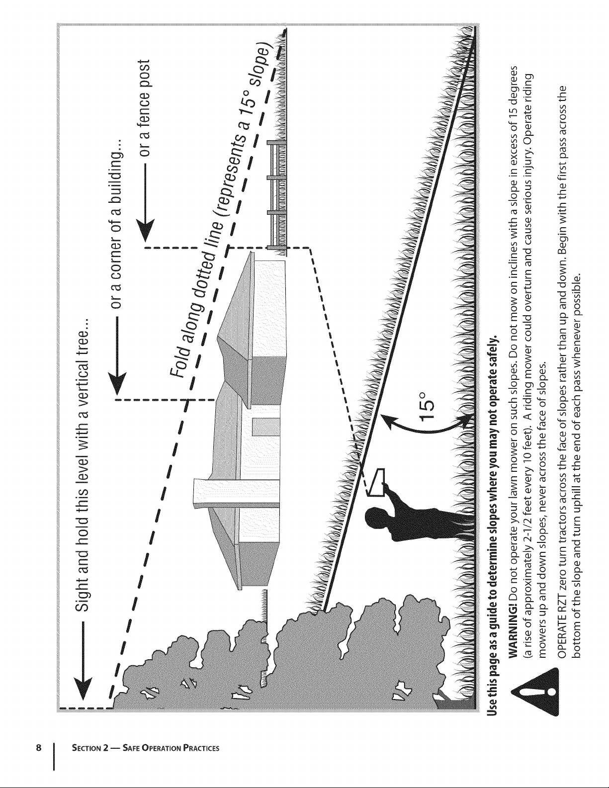
For your safety, use the slope gauge included as part of this
manual to measure slopes before operating this machine on
a sloped or hilly area. If the slope is greater than 15 degrees as
shown on the slope gauge, do not operate this machine on that
area or serious injury could result.
Do:
I.
Mow across slopes, not up and down. Exercise extreme
caution when changing direction on slopes.
2. Watch for holes, ruts, bumps, rocks, or other hidden
objects. Uneven terrain could overturn the machine. Tall
grass can hide obstacles.
3. Use slow speed. Choose a low enough speed so that you
will not have to stop while on the slope. Avoid starting
or stopping on a slope. If the tires are unable to maintain
traction, disengage the blades and proceed slowly and
carefully straight down the slope.
4. Follow the manufacturer's recommendations for wheel
weights or counterweights to improve stability.
5. Use extra care with grass catchers or other attachments.
These can change the stability of the machine.
6. Keep all movement on the slopes slow and gradual. Do
not make sudden changes in speed or direction. Rapid
acceleration or deceleration could cause the front of the
machine to lift and rapidly flip over backwards, which
could cause serious injury.
DoNot:
I. Do not turn on slopes unless necessary; then turn slowly
uphill and use extra care while turning.
2. Do not mow near drop-offs, ditches or embankments. The
mower could suddenly turn over if a wheel is over the edge
of a cliff, ditch, or if an edge caves in.
3. Do not try to stabilize the machine by putting your foot on
the ground.
4. Do not use a grass catcher on steep slopes.
5. Do not mow on wet grass. Reduced traction could cause
sliding.
6. Do not tow heavy pull behind attachments (e.g. loaded
dump cart, lawn roller, etc.) on slopes greater than 5
degrees. When going down hill, the extra weight tends
to push the tractor and may cause you to loose control
(e.g. tractor may speed up, braking and steering ability are
reduced, attachment may jack-knife and cause tractor to
overturn).
4 I SECTION 2 -- IMPORTANT SAFE OPERATION PRACTICES
Page 5
Children
1. Tragic accidents ca n occur if the operator is not alert to the
presence of children. Children are often attracted to the
machine and the mowing activity. They do not understand
the dangers. Never assume that children will remain where
you last saw them.
a. Keep children out of the mowing area and in
watchful care of a responsible adult other than the
operator.
b. Be alert and turn machine off if a child enters the
area.
c. To avoid back-over accidents, always look behind
and down for small children.
d. Never carry children, even with the blade(s) shut off.
They may fall offand be seriously injured or interfere
with safe machine operation.
e. Use extreme care when approaching blind corners,
doorways, shrubs, trees or other objects that may
blockyour vision of a child who may run into the
path of the machine.
f. Keep children away from hot or running engines.
They can suffer burns from a hot muffler.
g. Remove key when machine is unattended to
prevent unauthorized operation.
2. Never allow children under 14 years of age to operate this
machine. Children 14 and over should read and understand
the instructions and safe operation practices in this manual
and on the machine and should be trained and supervised
by an adult.
Towing
1. Tow only with a machine that has a hitch designed for
towing. Do not attach towed equipment except at the
hitch point.
2. Follow the manufacturers recommendation for weight
limits for towed equipment and towing on slopes.
3. Never allow children or others in or on towed equipment.
4. On slopes, the weight of the towed equipment may cause
loss of traction and loss of control.
5. Travel slowly and allow extra distance to stop.
6. Do not shift to neutral and coast downhill.
Service
SafeHandling of 6as01ine:
1. To avoid personal injury or property damage use extreme
care in handling gasoline. Gasoline is extremely
flammable and the vapors are explosive. Serious
personal injury can occur when gasoline is spilled on
yourself or your clothes which can ignite. Wash your skin
and change clothes immediately.
a. Use only an approved gasoline container.
b. Never fill containers inside a vehicle or on a truck
or trailer bed with a plastic liner. Always place
containers on the ground away from your vehicle
before filling.
c. When practical, remove gas-powered equipment
from the truck or trailer and refuel it on the ground.
If this is not possible, then refuel such equipment on
a trailer with a portable container, rather than from a
gasoline dispenser nozzle.
d. Keep the nozzle in contact with the rim of the fuel
tank or container opening at all times until fueling is
complete. Do not use a nozzle lock-open device.
e. Extinguish all cigarettes, cigars, pipes and other
sources of ignition.
f. Never fuel machine indoors.
g. Never remove gas cap or add fuel while the engine
is hot or running. Allow engine to cool at least two
minutes before refueling.
h. Never over fill fuel tank. Fill tank to no more than 1/2"
below bottom of filler neck to allow space for fuel
expansion.
i. Replace gasoline cap and tighten securely.
j. If gasoline is spilled, wipe it off the engine and
equipment. Move machine to another area. Wait 5
minutes before starting the engine.
k. To reduce fire hazards, keep machine free of grass,
leaves, or other debris build-up. Clean up oil or fuel
spillage and remove any fuel soaked debris.
I. Never store the machine or fuel container inside
where there is an open flame, spark or pilot light
as on a water heater, space heater, furnace, clothes
dryer or other gas appliances.
m. Allow a machine to cool at least five minutes before
storing.
6eneral Service
1. Never run an engine indoors or in a poorly ventilated area.
Engine exhaust contains carbon monoxide, an odorless,
and deadly gas.
2. Before cleaning, repairing, or inspecting, make certain the
blade(s) and all moving parts have stopped. Disconnect the
spark plug wire and ground against the engine to prevent
unintended starting.
3. Periodically check to make sure the blades come to
complete stop within approximately (5) five seconds after
operating the blade disengagement control. If the blades
do not stop within the this time frame, your machine
should be serviced professionally by an authorized dealer.
4. Regularly check the safety interlock system for proper
function, as described later in this manual. If the safety
interlock system does not function properly, have your
machine serviced professionally by an authorized dealer.
SECTION 2 -- IMPORTANT SAFE OPERATION PRACTICES S
Page 6
5. Check the blade(s) and engine mounting bolts at frequent
intervals for proper tightness. Also, visually inspect blade(s)
for damage (e.g., excessive wear, bent, cracked). Replace
the blade(s) with the original equipment manufacturer's
(O.E.M.)blade(s) only, listed in this manual. "Use of parts
which do not meet the original equipment specifications
may lead to improper performance and compromise
safety!"
6. Mower blades are sharp. Wrap the blade or wear gloves,
and useextra caution when servicing them.
7. Keep all nuts, bolts, and screws tight to be sure the
equipment isin safeworking condition.
8. Never tamper with the safety interlock system or other
safety devices. Check their proper operation regularly.
9. After striking a foreign object, stop the engine, disconnect
the spark plug wire(s) and ground against the engine.
Thoroughly inspect the machine for any damage. Repair
the damage before starting and operating.
10. Never attempt to make adjustments or repairs to the
machine while the engine is running.
11. Grasscatcher components and the discharge cover are
subject to wear and damage which could expose moving
parts or allow objects to be thrown. For safety protection,
frequently check components and replace immediately
with original equipment manufacturer's (O.E.M.)parts only,
listed in this manual. "Use of parts which do not meet the
original equipment specifications may lead to improper
performance and compromise safety!"
12. Do not change the engine governor settings or over-speed
the engine. The governor controls the maximum safe
operating speed of the engine.
13. Maintain or replace safety and instruction labels,as
necessary.
14. Observe proper disposal laws and regulations for gas,oil,
etc. to protect the environment.
15. According to the Consumer Products Safety Commission
(CPSC)and the U.S.Environmental Protection Agency (EPA),
this product hasan Average Useful Life of seven (7)years,
or 270 hours of operation. At the end of the Average Useful
Life have the machine inspected annually by an authorized
service dealer to ensure that all mechanical and safety
systems are working properly and not worn excessively.
Failure to do so can result in accidents, injuries or death.
Donot modifyengine
To avoid serious injury or death, do not modify engine in any
way. Tampering with the governor setting can lead to a runaway
engine and cause it to operate at unsafe speeds. Never tamper
with factory setting of engine governor.
NoticeRegardingEmissions
Engines which are certified to comply with California and federal
EPA emission regulations for SORE (Small Off Road Equipment)
are certified to operate on regular unleaded gasoline, and
may include the following emission control systems: Engine
Modification (EM) and Three Way Catalyst (TWC) if so equipped.
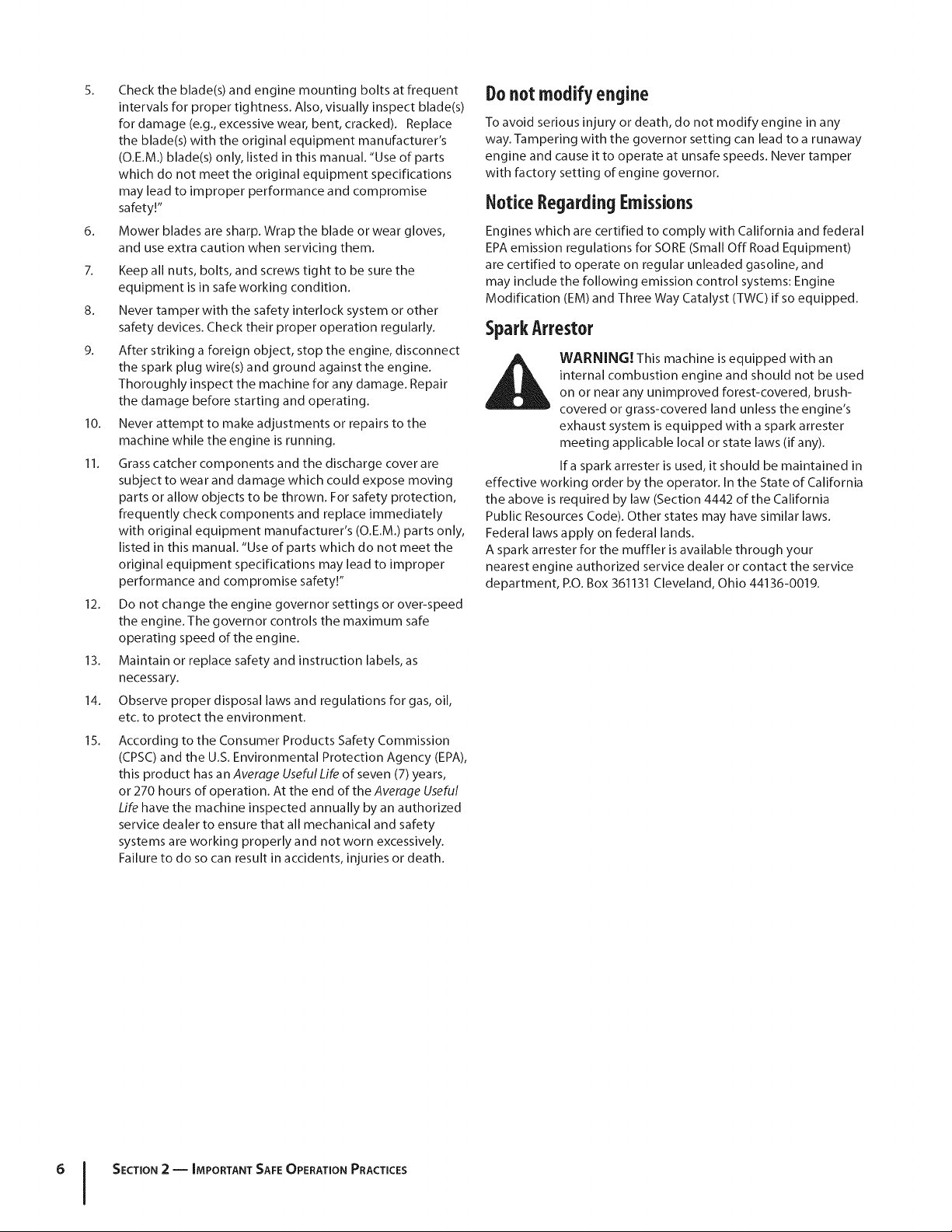
SparkArrestor
internal combustion engine and should not be used
i_lh WARNING! This machine is equipped with an
effective working order by the operator. In the State of California
the above is required by law (Section 4442 of the California
Public Resources Code). Other states may have similar laws.
Federal laws apply on federal lands.
A spark arrester for the muffler is available through your
nearest engine authorized service dealer or contact the service
department, RO. Box 361131 Cleveland, Ohio 44136-0019.
on or near any unimproved forest-covered, brush-
covered or grass-covered land unless the engine's
exhaust system is equipped with a spark arrester
meeting applicable local or state laws (if any).
If a spark arrester is used, it should be maintained in
6 I SECTION 2 -- IMPORTANT SAFE OPERATION PRACTICES
Page 7
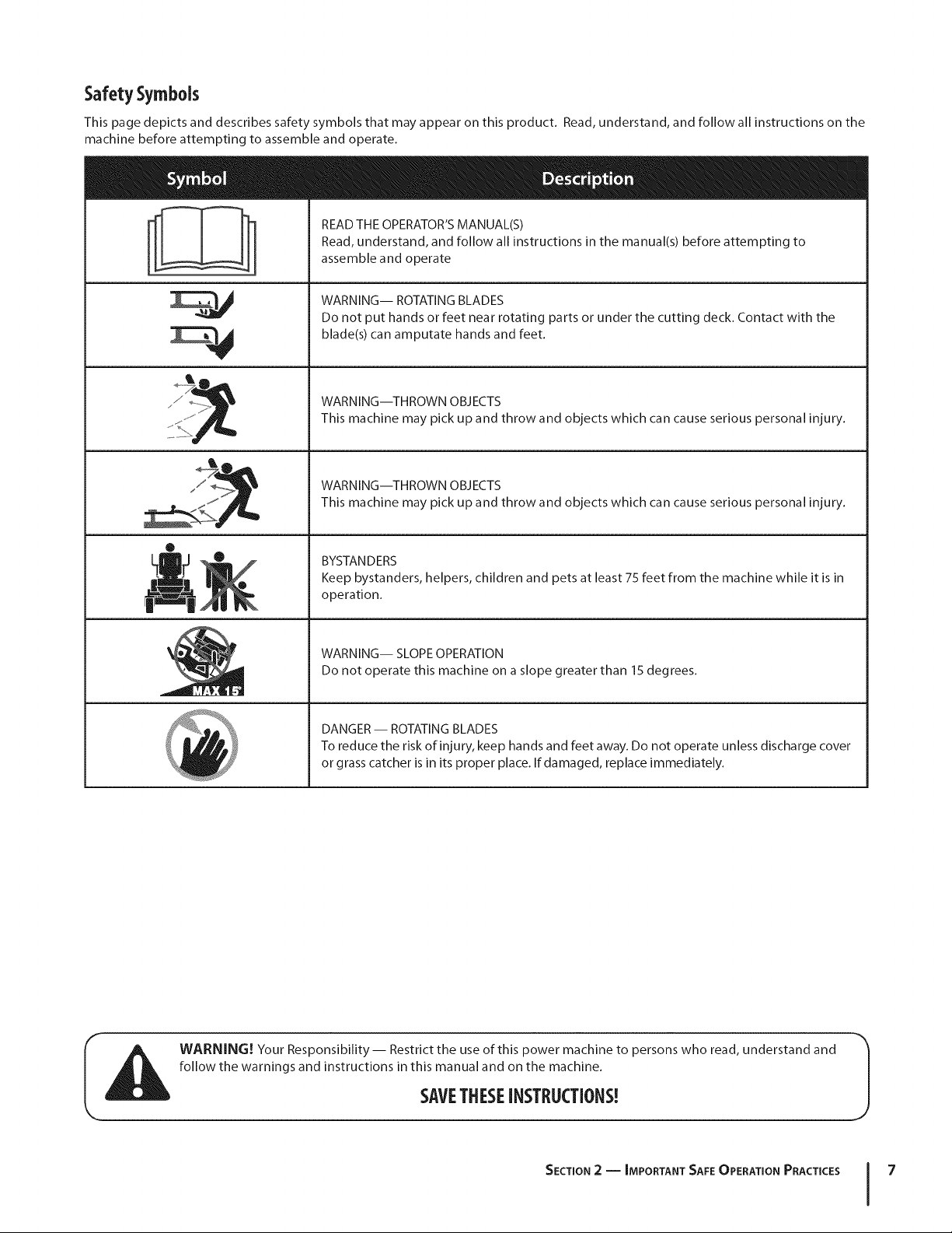
Safety Symbols
This page depicts and describes safety symbols that may appear on this product. Read, understand, and follow all instructions on the
machine before attempting to assemble and operate.
READ THE OPERATOR'S MANUAL(S)
Read, understand, and follow all instructions in the manual(s) before attempting to
assemble and operate
M
®
!!l"
N
WARNING-- ROTATING BLADES
Do not put hands or feet near rotating parts or under the cutting deck. Contact with the
blade(s) can amputate hands and feet.
WARNING--THROWN OBJECTS
This machine may pick up and throw and objects which can cause serious personal injury.
WARNING--THROWN OBJECTS
This machine may pick up and throw and objects which can cause serious personal injury.
BYSTANDERS
Keep bystanders, helpers, children and pets at least 75 feet from the machine while it is in
operation.
WARNING-- SLOPE OPERATION
Do not operate this machine on a slope greater than 15 degrees.
DANGER -- ROTATING BLADES
To reduce the risk of injury, keep hands and feet away. Do not operate unless discharge cover
or grass catcher is in its proper place. If damaged, replace immediately.
WARNING! Your Responsibility-- Restrict the use of this power machine to persons who read, understand and
follow the warnings and instructions in this manual and on the machine.
SAVETHESEINSTRUCTIONS!
SECTION 2 -- IMPORTANT SAFE OPERATION PRACTICES 7
Page 8
¢'-
c_
c_O
O
¢-
(D
c_
_iii!i
.CC
c5
(D
c_
c.3
L_
;>
c_
(D
Co
¢-
©
r--
_r
c
©
c.)
c_
©
I
!
I
I
l
l
l
l
l
l
l
l
l
l
l
l
l
o
LO
I
/
/
/
/
/
c-
c_
/
I
oO
I
/
/
SECTION 2 -- SAFE OPErATiON PRACTICES
Page 9
Assembly& Set-Up
Contents of Crate
3
One Lawn Tractor
One RZT Tractor Operator's
Manual
NOTE:This Operator's Manual covers several models. Tractor
features may vary by model. Not all features in this manual are
applicable to all snow thrower models and the snow thrower
depicted may differ from yours.
One Oil Drain Hose (If Equipped)
One Engine Operator's Manual
TractorPreparation
Remove the upper crating material from the shipping pallet, and
cut any bands or tie straps securing the tractor to the pallet.
Use the lift handle to raise the deck to its highest position.
Engage the transmission bypass rods on each side of the
tractor; then carefully roll the tractor off the shipping pallet.
The transmission bypass rods (one for each the RH and LH
transmission) are located beneath the frame platform, just inside
each rear wheel. Disengage the bypass rods. See Fig. 3-1.
RH Transmission
Bypass Rod
Pull Out Bypass
Rod Then Lower i
into Slot
One Deck Wash Hose Coupler
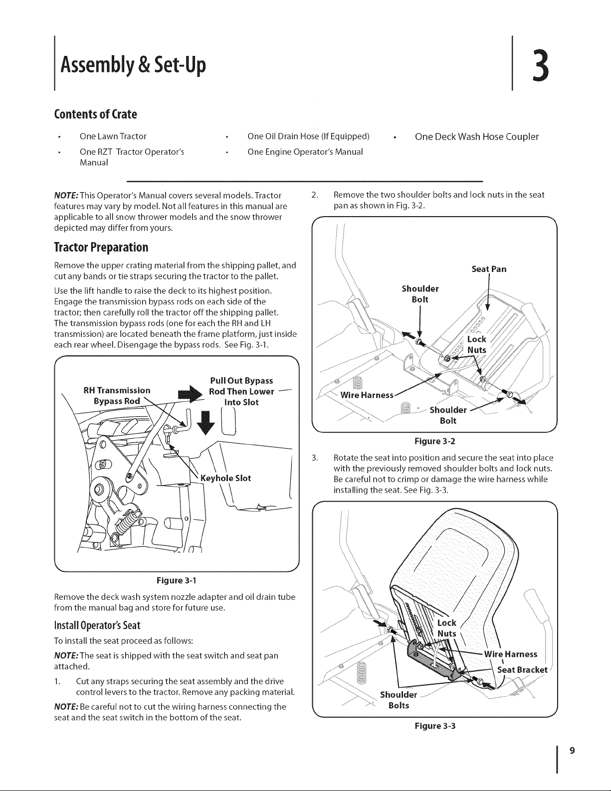
2.
Remove the two shoulder bolts and lock nuts in the seat
_an as shown in Fig. 3-2.
r"
Seat Pan
Shoulder
Bolt
Keyhole Slot
Figure 3-1
Remove the deck wash system nozzle adapter and oil drain tube
from the manual bag and store for future use.
Install Operator'sSeat
To install the seat proceed as follows:
NOTE:The seat is shipped with the seat switch and seat pan
attached.
1. Cut any straps securing the seat assembly and the drive
control levers to the tractor. Remove any packing material.
NOTE: Be careful not to cut the wiring harness connecting the
seat and the seat switch in the bottom of the seat.
Figure 3=2
3.
Rotate the seat into position and secure the seat into place
with the previously removed shoulder bolts and lock nuts.
Be careful not to crimp or damage the wire harness while
i
J
installing the seat. See Fig. 3-3.
Shoulder
Bolts
J
Figure 3=3
Page 10
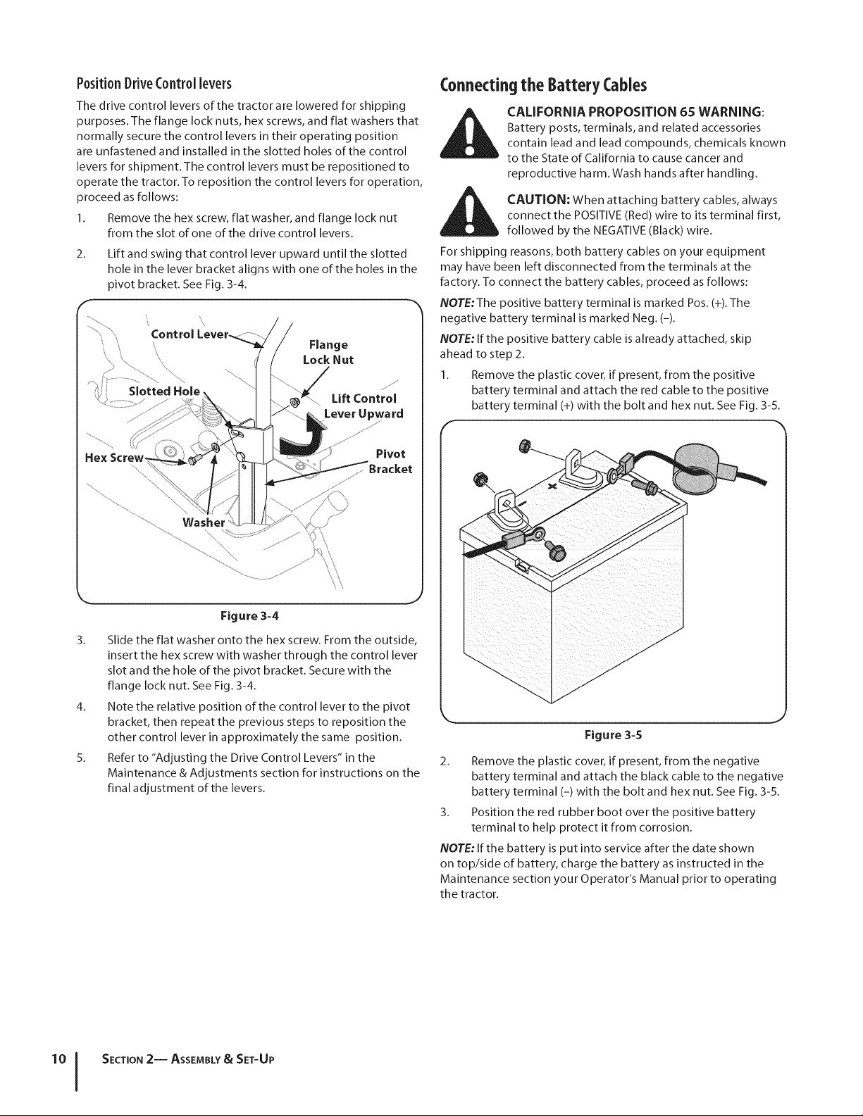
Position DriveControllevers
The drive control levers of the tractor are lowered for shipping
purposes. The flange lock nuts, hex screws, and flat washers that
normally secure the control levers in their operating position
are unfastened and installed in the slotted holes of the control
levers for shipment. The control levers must be repositioned to
operate the tractor. To reposition the control levers for operation,
proceed as follows:
Remove the hex screw, flat washer, and flange lock nut
from the slot of one of the drive control levers.
2.
Lift and swing that control lever upward until the slotted
hole in the lever bracket aligns with one of the holes in the
pivot bracket. See Fig. 3-4.
Lift Control
Lever Upward
Pivot
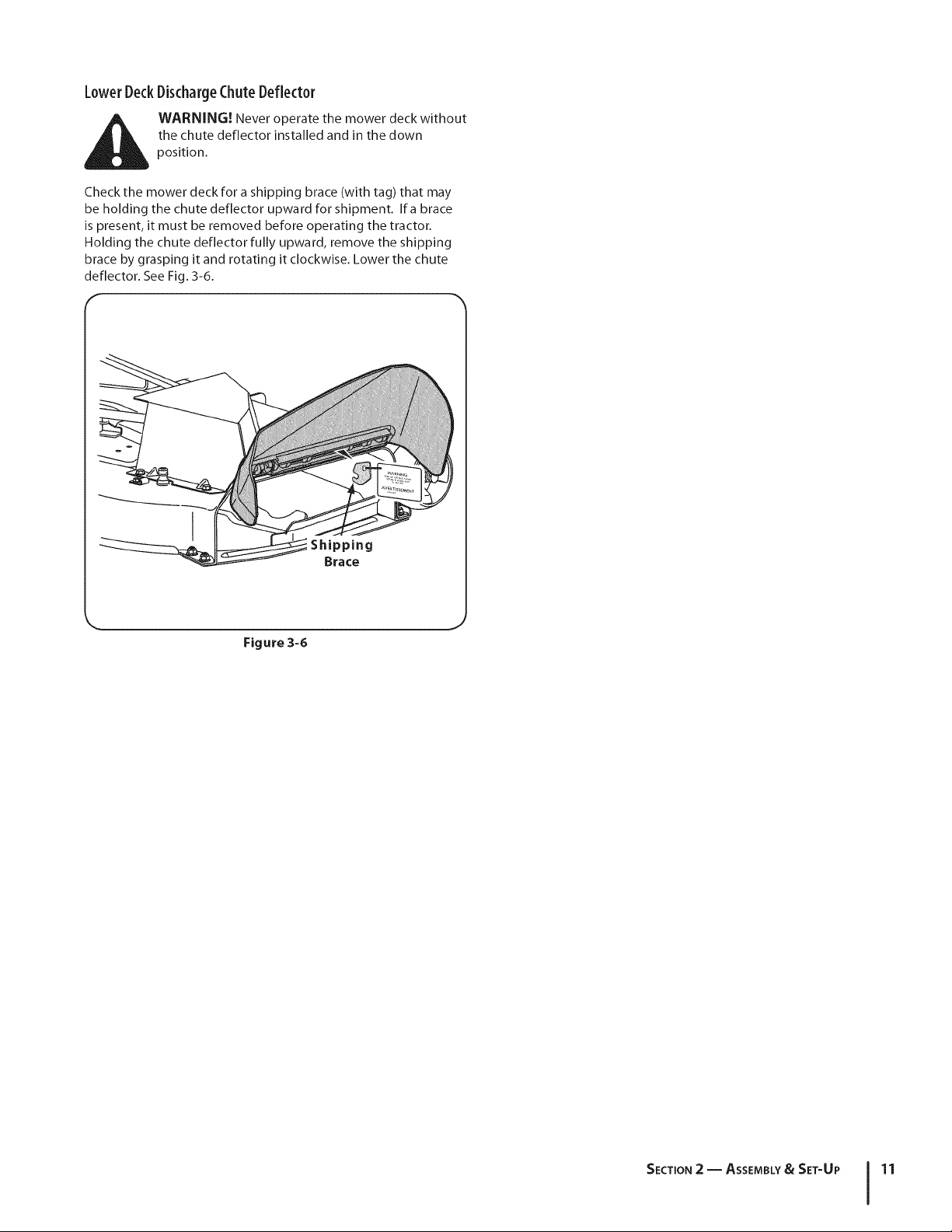
Connectingthe BatteryCables
CALIFORNIA PROPOSITION 65 WARNING:
Battery posts, terminals, and related accessories
contain lead and lead compounds, chemicals known
to the State of California to cause cancer and
reproductive harm. Wash hands after handling.
CAUTION: When attaching battery cables, always
connect the POSITIVE (Red) wire to its terminal first,
followed by the NEGATIVE (Black) wire.
For shipping reasons, both battery cables on your equipment
may have been left disconnected from the terminals at the
factory. To connect the battery cables, proceed as follows:
NOTE:The positive battery terminal is marked Pos. (+). The
negative battery terminal is marked Neg. (-).
NOTE: If the positive battery cable is already attached, skip
ahead to step 2.
1. Remove the plastic cover, if present, from the positive
battery terminal and attach the red cable to the positive
battery terminal (+) with the bolt and hex nut. See Fig. 3-5.
r
Figure 3-4
3. Slide the flat washer onto the hex screw. From the outside,
insert the hex screw with washer through the control lever
slot and the hole of the pivot bracket. Secure with the
flange lock nut. See Fig. 3-4.
4. Note the relative position of the control lever to the pivot
bracket, then repeat the previous steps to reposition the
other control lever in approximately the same position.
5. Refer to "Adjusting the Drive Control Levers" in the
Maintenance & Adjustments section for instructions on the
final adjustment of the levers.
Figure 3-5
2. Remove the plastic cover, if present, from the negative
battery terminal and attach the black cable to the negative
battery terminal (-) with the bolt and hex nut. See Fig. 3-5.
3. Position the red rubber boot over the positive battery
terminal to help protect it from corrosion.
NOTE: If the battery is put into service after the date shown
on top/side of battery, charge the battery as instructed in the
Maintenance section your Operator's Manual prior to operating
the tractor.
SECTION 2-- ASSEMBLY& SET-UP
Page 11
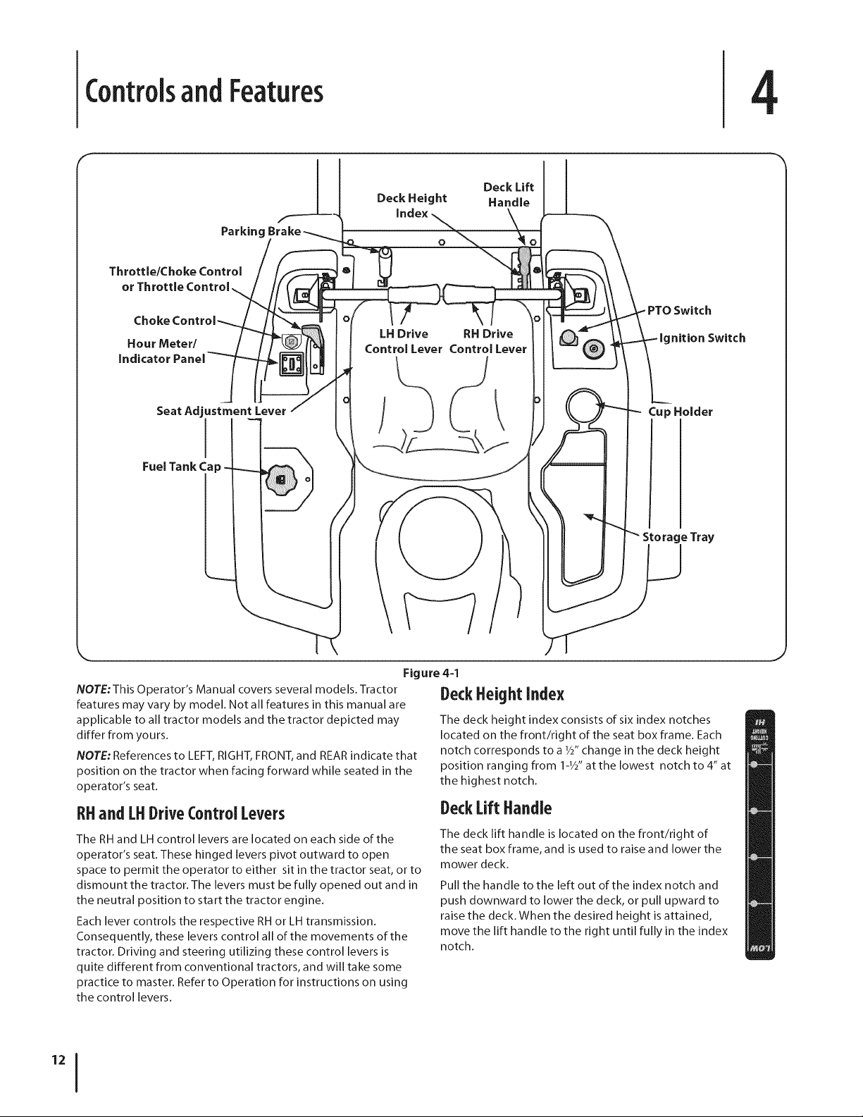
LowerDeckDischargeChuteDeflector
the chute deflector installed and in the down
WARNING! Never operate the mower deck without
position.
Check the mower deck for a shipping brace (with tag) that may
be holding the chute deflector upward for shipment. Ira brace
is present, it must be removed before operating the tractor.
Holding the chute deflector fully upward, remove the shipping
brace by grasping it and rotating it clockwise. Lower the chute
deflector. See Fig. 3-6.
Figure 3=6
SECTION 2 -- ASSEMBLY& SET-UP 11
Page 12
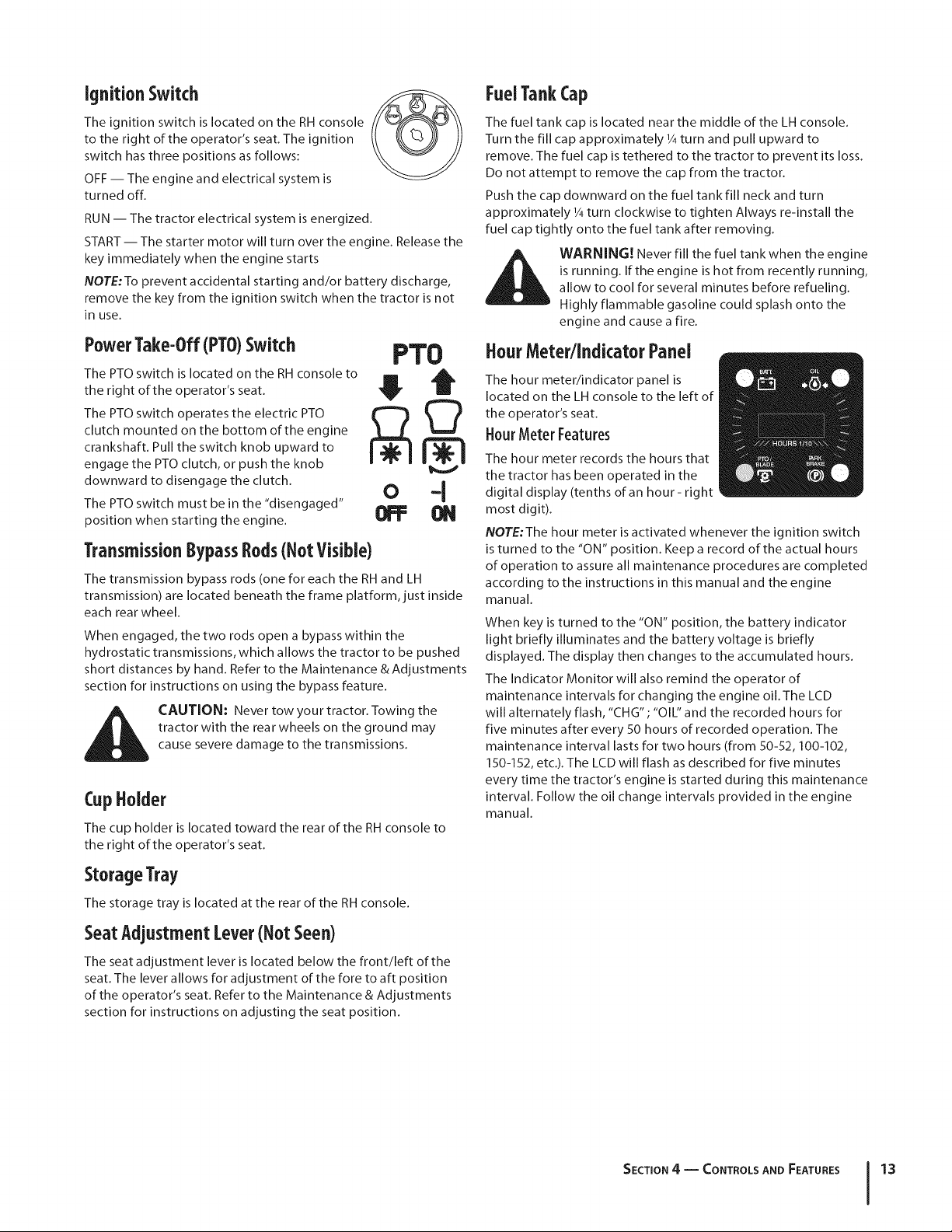
ControlsandFeatures
F
4
Throttl_
Hour Meter/
indicator
Fuel Tank Ca
Parking Brake
Seat Adjustment Lever
I
Deck Height
index
O
LH Drive RH Drive
Control Lever Control Lever
Deck Lift
Handle
Switch
nition Switch
Cup Holder
Tray
Figure 4-1
NOTE:This Operator's Manual covers several models. Tractor
features may vary by model. Not all features in this manual are
applicable to all tractor models and the tractor depicted may
differ from yours.
NOTE: References to LEFT, RIGHT, FRONT, and REAR indicate that
position on the tractor when facing forward while seated in the
operator's seat.
RHandLHDriveControl Levers
The RH and LH control levers are located on each side of the
operator's seat. These hinged levers pivot outward to open
space to permit the operator to either sit in the tractor seat, or to
dismount the tractor. The levers must be fully opened out and in
the neutral position to start the tractor engine.
Each lever controls the respective RH or LH transmission.
Consequently, these levers control all of the movements of the
tractor. Driving and steering utilizing these control levers is
quite different from conventional tractors, and will take some
practice to master. Refer to Operation for instructions on using
the control levers.
DeckHeightIndex
The deck height index consists of six index notches
located on the front/right of the seat box frame. Each
notch corresponds to a 1/S'change in the deck height
position ranging from 1-1/2"at the lowest notch to 4" at
the highest notch.
DeckLift Handle
The deck lift handle is located on the front/right of
the seat box frame, and is used to raise and lower the
mower deck.
Pull the handle to the left out of the index notch and
push downward to lower the deck, or pull upward to
raise the deck. When the desired height is attained,
move the lift handle to the right until fully in the index
notch.
Page 13
ignition Switch
The ignition switch is located on the RH console
to the right of the operator's seat. The ignition
switch has three positions as follows:
OFF -- The engine and electrical system is
turned off.
RUN -- The tractor electrical system is energized.
START-- The starter motor will turn over the engine. Release the
key immediately when the engine starts
NOTE:To prevent accidental starting and/or battery discharge,
remove the key from the ignition switch when the tractor is not
in use.
PowerTake-Off(PTO)Switch
The PTO switch is located on the RH console to
the right of the operator's seat.
The PTO switch operates the electric PTO
clutch mounted on the bottom of the engine
crankshaft. Pull the switch knob upward to
engage the PTO clutch, or push the knob
downward to disengage the clutch.
The PTO switch must be in the "disengaged"
position when starting the engine.
PTO
I Q
0 -J
Transmission BypassRods(Not Visible)
The transmission bypass rods (one for each the RH and LH
transmission) are located beneath the frame platform, just inside
each rear wheel.
When engaged, the two rods open a bypass within the
hydrostatic transmissions, which allows the tractor to be pushed
short distances by hand. Refer to the Maintenance & Adjustments
section for instructions on using the bypass feature.
tractor with the rear wheels on the ground may
CAUTION: Never tow your tractor. Towing the
cause severe damage to the transmissions.
CupHolder
The cup holder is located toward the rear of the RH console to
the right of the operator's seat.
FuelTankCap
The fuel tank cap is located near the middle of the LH console.
Turn the fill cap approximately 1/4turn and pull upward to
remove. The fuel cap is tethered to the tractor to prevent its loss.
Do not attempt to remove the cap from the tractor.
Push the cap downward on the fuel tank fill neck and turn
approximately 1/4turn clockwise to tighten Always re-install the
fuel cap tightly onto the fuel tank after removing.
is running. If the engine is hot from recently running,
ill_li WARNING! Never fill the fuel tank when the engine
allow to cool for several minutes before refueling.
Highly flammable gasoline could splash onto the
engine and cause a fire.
HourMeter/IndicatorPanel
The hour meter/indicator panel is
located on the LH console to the left of
the operator's seat.
HourMeter Features
The hour meter records the hours that
the tractor has been operated in the
digital display (tenths of an hour- right
most digit).
NOTE:The hour meter is activated whenever the ignition switch
is turned to the "ON" position. Keep a record of the actual hours
of operation to assure all maintenance procedures are completed
according to the instructions in this manual and the engine
manual.
When key is turned to the "ON" position, the battery indicator
light briefly illuminates and the battery voltage is briefly
displayed. The display then changes to the accumulated hours.
The Indicator Monitor will also remind the operator of
maintenance intervals for changing the engine oil. The LCD
will alternately flash, "CHG" ; "OIL" and the recorded hours for
five minutes after every 50 hours of recorded operation. The
maintenance interval lasts for two hours (from 50-52,100-102,
150-152, etc.). The LCD will flash as described for five minutes
every time the tractor's engine is started during this maintenance
interval. Follow the oil change intervals provided in the engine
manual.
StorageTray
The storage tray is located at the rear of the RH console.
SeatAdjustmentLever(NotSeen)
The seat adjustment lever is located below the front/left of the
seat. The lever aIlows for adjustment of the fore to aft position
of the operator's seat. Refer to the Maintenance & Adjustments
section for instructions on adjusting the seat position.
SECTION4 -- CONTROLS AND FEATURES 13
Page 14
Indicator Panel Features
Battery Indicator
Illuminates and the battery voltage is displayed briefly when the
ignition switch it turned to the "ON" position.
Illuminates to indicate the battery voltage has dropped below
11.5 (+0.5/-1.0) volts. The battery voltage is also displayed on
the hour meter. If this indicator and display come on during
operation, check the battery and charging system for possible
causes and/or contact your Cub Cadet dealer.
Oil Pressure Indicator (If Engine So Equipped)
This warning lamp indicates low engine oil pressure. If the
indicator comes on while the engine is running, stop the engine
immediately and check for possible causes. Do not run the
engine while this indicator is illuminated. Contact your Cub
Cadet dealer to have the tractor and engine inspected.
NOTE:The oil pressure indicator may illuminate when the
ignition switch is in the ON position, but should turn offwhen
the engine is started.
PTO Engaged Indicator
This indicator illuminates when the PTO switch is pulled upward
in the "ENGAGED" position and the ignition switch is turned
to the "START" position. Check this indicator if the engine will
not crank with the ignition switch in the "START" position. If
necessary, move the PTO switch to the "DISENGAGED" position.
Parking Brake Engaged Indicator
This indicator illuminates when the parking brake is in the
DISENGAGED position and the ignition switch is turned to the
"START" position. Check this indicator if the engine will not crank
with the ignition switch in the "START" position. If necessary,
move the parking brake to the ENGAGED position.
This indicator also illuminates when the ignition switch is turned
to the "START" position and the RH and/or LH drive control levers
are in a position other than the fully out in neutral position. Move
the control levers fully outward.
ThrottleControl (if Equipped)
The throttle control is located on the LH console to the
left of the operator's seat. When set in a given position, a
uniform engine speed will be maintained.
Push the throttle control handle forward to increase the
engine speed. The tractor is designed to operate with the
throttle control in the fast position (full throttle) when the
tractor is being driven and the mower deck is engaged.
Pull the throttle control handle rearward to decrease the
engine speed.
I Under normal operating conditions, no oil should be added
m
SLOW
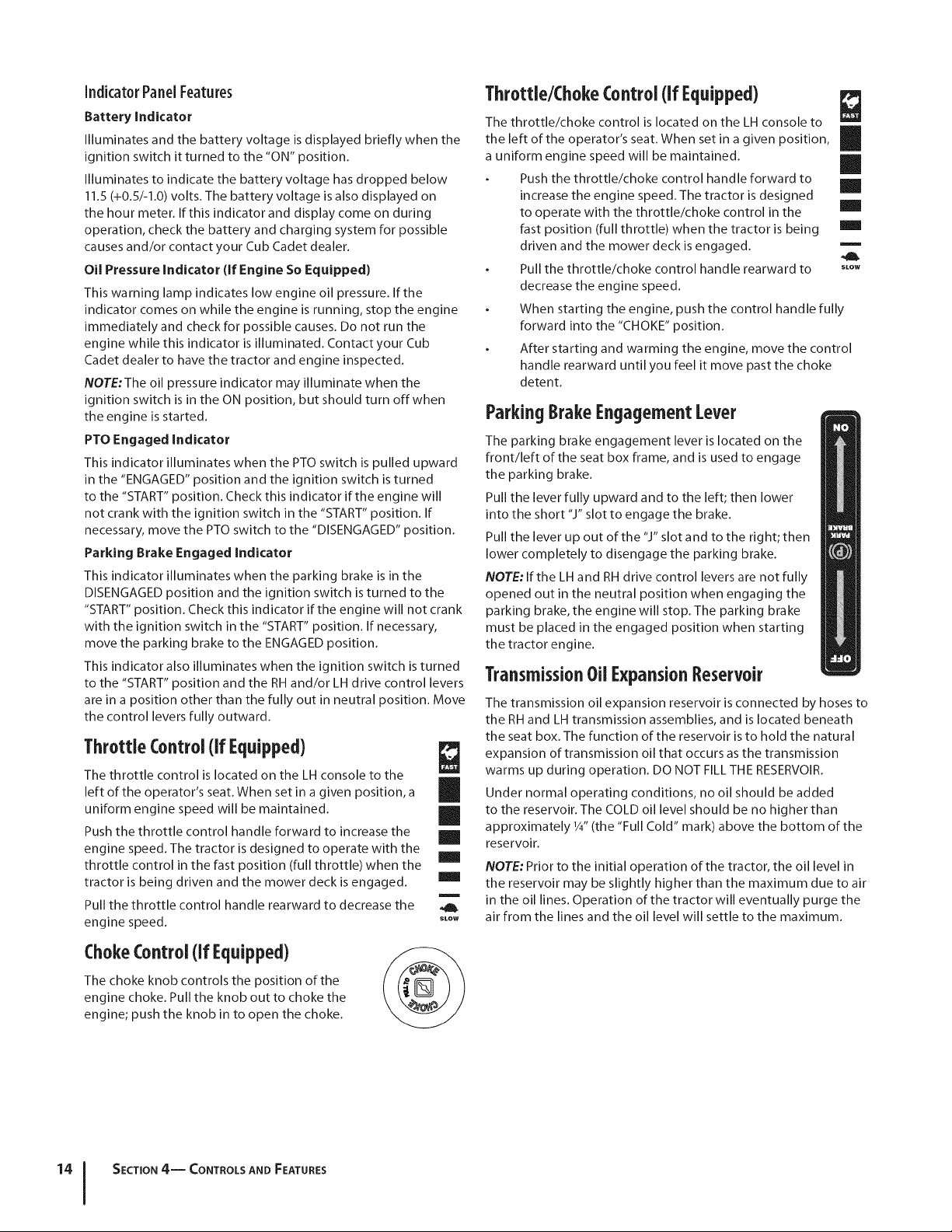
Throttle/ChokeControl (if Equipped)
The throttle/choke control is located on the LH console to _,m
the left of the operator's seat. When set in a given position,
a uniform engine speed will be maintained.
Push the throttle/choke control handle forward to
increase the engine speed. The tractor is designed
to operate with the throttle/choke control in the
fast position (full throttle) when the tractor is being
driven and the mower deck is engaged.
Pull the throttle/choke control handle rearward to slow
decrease the engine speed.
When starting the engine, push the control handle fully
forward into the "CHOKE" position.
After starting and warming the engine, move the control
handle rearward until you feel it move past the choke
detent.
ParkingBrakeEngagementLever
The parking brake engagement lever is located on the
front/left of the seat box frame, and is used to engage
the parking brake.
Pull the lever fully upward and to the left; then lower
into the short "J" slot to engage the brake.
Pull the lever up out of the "J" slot and to the right; then
lower completely to disengage the parking brake.
NOTE: If the LH and RH drive control levers are not fully
opened out in the neutral position when engaging the
parking brake, the engine will stop. The parking brake
must be placed in the engaged position when starting
the tractor engine.
TransmissionOilExpansionReservoir
The transmission oil expansion reservoir is connected by hoses to
the RH and LH transmission assemblies, and is located beneath
the seat box. The function of the reservoir is to hold the natural
expansion of transmission oil that occurs as the transmission
warms up during operation. DO NOT FILL THE RESERVOIR.
to the reservoir. The COLD oil level should be no higher than
approximately 1/4"(the "Full Cold" mark) above the bottom of the
reservoir.
NOTE: Prior to the initial operation of the tractor, the oil level in
the reservoir may be slightly higher than the maximum due to air
in the oil lines. Operation of the tractor will eventually purge the
air from the lines and the oil level will settle to the maximum.
ChokeControl(If Equipped)
The choke knob controls the position of the
engine choke. Pull the knob out to choke the
engine; push the knob in to open the choke.
SECTION 4-- CONTROLS AND FEATURES
Page 15

Operation
5
GeneralSafety
RECEIVE INSTRUCTION -- Entirely read this operator's
manual. Learn to operate this machine SAFELY.Do not risk
INJURY or DEATH. Allow only those who have become
competent in its usage to operate this tractor.
Before starting the engine or beginning operation, be
familiar with the controls. The operator should be in the
operator's seat. The PTO switch must be in the disengaged
position, the parking brake engaged, and the RH and LH
drive control levers moved fully outward in the neutral
position.
Keep all shields in place. Keep away from moving parts.
NO RIDERS! Keep all people and pets a safe distance away.
Look behind and down to both sides of the tractor before
and while backing up.
DO NOT direct the mower discharge at people.
Avoid slopes where possible. Never operate on slopes
greater than 15°. Slopes with a greater incline present
dangerous operating conditions. Tractors can be rolled
over.
Before leaving the operator's seat: Shut off the PTO, move
the RH and LH drive control levers fully outward in the
neutral position, engage the parking brake, shut off the
engine and remove the ignition key. Wait for all movement
to stop before servicing or cleaning.
Operate the drive control levers smoothly and avoid
any sudden movements of the levers when starting and
stopping. Keep a firm grip on the control levers.
Be careful when operating near roadways. Stop the tractor
motion and wait for vehicles to pass before operating
along the road.
Do not operate the tractor with the mower deck removed.
Removal of the deck will change the balance of the tractor,
and could contribute to a tractor rollover.
Avoid operation on traction surfaces that are unstable; use
extreme caution if the surface is slippery.
Slow down before turning and come to a complete stop
before any zero turn maneuver.
Do not stop the tractor or park the tractor over
combustible materials such as dry grass, leaves, debris, etc.
Do not fill the fuel tank when the engine is running or
while the engine is hot. Allow the engine several minutes
to cool before refueling. Tighten the fuel cap securely.
BeforeOperatingYourTractor
Before you operate the tractor, study this manual carefully
to familiarize yourself with the operation of all the
instruments and controls. It has been prepared to help you
operate and maintain your tractor efficiently.
This engine is certified to operate only on clean, fresh,
unleaded regular gasoline. For best results, fill the fuel
tank with only clean, fresh, unleaded gasoline with a pump
sticker octane rating of 87 or higher.
Unleaded gasoline is recommended because it leaves
less combustion chamber deposits and reduces harmful
exhaust emissions. Leaded gasoline is not recommended
and must not be used where exhaust emissions are
regulated.
NOTE: Purchase gasoline in small quantities. Do not use
gasoline left over from the previous season, to minimize
gum deposits in the fuel system.
Gasohol (up to 10% ethyl alcohol, 90% unleaded gasoline
by volume) is an approved fuel. Other gasoline/alcohol
blends are not approved.
Methyl Tertiary Butyl Ether (MTBE) and unleaded gasoline
blends (up to a maximum of 15% MTBE by volume) are
approved fuels. Other gasoline/ether blends are not
approved.
Check the engine oil level.
Clean the air cleaner element if necessary.
Check the tire inflation pressures.
Adjust the seat for operator's maximum comfort, visibility
and for maintaining complete control of the tractor.
SafetyinterlockSystem
This tractor is equipped with a safety interlock system for the
protection of the operator. If the interlock system should ever
malfunction, do not operate the tractor. Contact your authorized
Cub Cadet Dealer.
The safety interlock system prevents the engine from
cranking or starting unless the RH and LH drive control
levers are moved fully outward in the neutral position, the
parking brake is engaged, and the PTO is disengaged.
To avoid sudden movement when disengaging the parking
brake, the safety interlock system will shut offthe engine
if the RH and/or LH drive control levers are moved to a
position other than the fully out in the neutral position
when the parking brake is engaged.
The safety interlock system will shut off the engine if the
operator leaves the seat before engaging the parking
brake.
15
Page 16

The safety interlock system will shut offthe engine if the
operator leaves the seat with the PTO engaged, regardless
of whether the parking brake is engaged.
NOTE:The PTO switch must be moved to the "OFF"
position to restart the engine.
The safety interlock system will shut offthe PTO and the
mower blades will stop if both drive control levers are
moved into the reverse position. The PTO will re-engage
when one or both of the levers are moved back to the
neutral or forward position.
Starting the Engine
WARNING! This tractor is equipped with a safety
interlock system designed for the protection of the
operator. Do not operate the tractor if any part of
the interlock system is malfunctioning. Periodically
check the functions of the interlock system for
proper operation.
WARNING! For personal safety, the operator must
be sitting in the tractor seat when starting the
engine.
SeparateThrottleand Choke
1. Operator must be sitting in the tractor seat.
2. Engage the parking brake. Refer to Fig. 5-1.
LH Control Lever
Out in Neut__L_ral Parking Brake
Throttle/Choke
_Control or Throttle
Control
RH Control Lever
Out in Neutral
)
'Choke J /
/ __J PTO Switch
(Disengaged) Position
in Down
6. Turn the ignition key clockwise to the "START" position
and release it as soon as the engine starts; however, do not
crank the engine continuously for more than 5 seconds at
a time. If the engine does not start within this time, turn
the key to "OFF" and wait at least 15 seconds to allow the
engine's starter motor to cool. Try again after waiting. If
after a few attempts the engine fails to start, do not keep
trying to start it with the choke closed as this will cause
flooding and make starting more difficult.
7. As the engine warms up, gradually push the choke control
into the off position. Do not use the choke to enrich the
fuel mixture, except as necessary to start the engine.
8. Allow the engine to run for a few minutes at mid throttle
before putting the engine under load.
9. Observe the hour meter / indicator panel. If the battery
indicator light or oil pressure light come on, immediately
stop the engine. Have the tractor inspected by your Cub
Cadet dealer.
Thr0ttle/Ch0ke ControlLeverSet-Up
1. Operator must be sitting in the tractor seat.
2. Engage the parking brake. Refer to Fig. 5-1.
3. Make certain the PTO switch is in the disengaged (down)
position. Refer to Fig. 5-1.
4. Insert the tractor key into the ignition switch module.
5. Turn the ignition key clockwise to the "START" position
and release it as soon as the engine starts; however, do not
crank the engine continuously for more than 5 seconds at
a time. If the engine does not start within this time, turn
the key to "OFF" and wait at least 15 seconds to allow the
engine's starter motor to cool. Try again after waiting. If
after a few attempts the engine fails to start, do not keep
trying to start it with the choke closed as this will cause
flooding and make starting more difficult.
6. As the engine warms up, gradually pull the throttle control
lever rearward past the choke detent position. Do not use
the choke position to enrich the fuel mixture, except as
necessary to start the engine.
7. Allow the engine to run for a few minutes at mid throttle
before putting the engine under load.
8. Observe the hour meter / indicator panel. If the battery
indicator light or oil pressure light come on, immediately
stop the engine. Have the tractor inspected by your Cub
Cadet dealer.
_J
Figure 5-1
3. Make certain the PTO switch is in the disengaged (down)
position. Refer to Fig. 5-1.
4. Pull the choke control upward into the full choke position
NOTE: If the engine is warmed up, it may not be necessary
to place the throttle control in the choke position.
5. Move the throttle control to midway between its SLOW and
FAST positions.
SECTION S-- OPERATION
ColdWeatherStarting
When starting the engine at temperatures near or below
freezing, ensure the correct viscosity motor oil is used in the
engine and the battery is fully charged. Start the engine as
follows:
1. Be sure the battery is in good condition. A warm battery
has much more starting capacity than a cold battery.
2. Use fresh winter grade fuel. Winter grade gasoline has
higher volatility to improve starting. Do not use gasoline
left over from summer.
3. Follow the previous instruction for Starting the Engine.
Page 17

UsingJumperCablesToStart Engine
Drivingthe Tractor
produce explosive gasses. Make certain the area is
WARNING! Batteries contain sulfuric acid and
well ventilated, wear gloves and eye protection, and
avoid sparks or flames near the battery.
If the battery charge is not sufficient to crank the engine,
recharge the battery. Ira battery charger is unavailable and
the tractor must be started, the aid of a booster battery will be
necessary. Connect the booster battery as follows:
I. Connect the end of one cable to the disabled tractor
battery's positive terminal; then connect the other end of
that cable to the booster battery's positive terminal.
2. Connect one end of the other cable to the booster
battery's negative terminal; then connect the other end of
that cable to the frame of the disabled tractor, as far from
the battery as possible.
3. Start the disabled tractor following the normal starting
instructions previously provided; then disconnect
the jumper cables in the exact reverse order of their
connection.
4.
Have the tractor's electrical system checked and repaired
as soon as possible to eliminate the need for jump starting.
Stoppingthe Engine
I. Place the PTO switch in the "OFF" position.
2. Move the RH and LH drive control levers fully outward in
the neutral position.
3. Engage the parking brake.
4. Move the throttle control to the SLOW position and allow
the engine to idle for about one minute.
5. Turn the ignition key to the "OFF" position and remove the
key from the ignition switch.
NOTE: Always remove the key from the ignition switch to prevent
accidental starting or battery discharge if the equipment is left
unattended.
PracticeOperation (Initial Use)
Operating a zero-turn tractor is not like operating a conventional
type riding tractor. Although and because a zero turn tractor is
more maneuverable, getting used to operating the control levers
takes some practice.
We strongly recommend that you locate a reasonably large,
level and open "practice area" where there are no obstructions,
pedestrians, or animals. You should practice operating the
tractor for a minimum of 30 minutes.
Carefully move (or have moved) the tractor to the practice area.
When performing the practice session, the PTO should not be
engaged. While practicing, operate the tractor at approximately
1/2-3Athrottle and at less than full speed in both forward and
reverse.
Carefully practice maneuvering the tractor using the instructions
in the following section "Driving the Tractor." Practice until you
are confident that you can safely operate the tractor.
i_ WARNING! Avoid sudden starts, excessive speed
and sudden stops.
1. Adjust the operator's seat to the most comfortable
position that allows you to operate the controls. See seat
adjustment in the Maintenance & Adjustments section.
2. Release the parking brake.
3. Move the RH and LH drive control levers inward in the
neutral position. Refer to Figure 5-2.
Control Lever Moved
inward and in Neutral
/
Figure 5-2
NOTE: If the control levers are not even in the neutral position,
refer to Maintenance & Adjustments for instructions to adjust the
levers so that they are even.
4. Move the throttle control lever forward to the full throttle
position (3300-3500 RPM).
NOTE:Although the tractor's engine is designed to run at
full throttle, when performing a practice session the tractor
must be operated at less than full throttle (approximately
2500-3000 RPM). This only applies to practice.
control levers. DO NOT release the control levers to
_IILI WARNING! Always maintain a firm grip on the
5. To drive the tractor, firmly grasp the respective drive
slow or stop the tractor; move levers to neutral
position using your hands.
control levers with your right and left hands and continue
with Driving the Tractor Forward on the following page.
J
SECTION S -- OPERATION 17
Page 18

Drivingthe TractorForward
WARNING! Keep all movement of the drive control
levers slow and smooth. Abrupt movement of the
control levers can affect the stability of the tractor
and could cause the tractor to flip over, which may
result in serious injury or death to the operator.
1. Slowly and evenly move both drive control levers forward.
The tractor will start to move forward. See Fig. 5-3.
Driving Forward
Faster
1. To turn to the left, move the left drive control lever
rearward of the right lever. See Fig. 5-4.
Forward Left Turn
F---12
,,. j
Figure 5-4
2. To turn to the right, move the right drive control lever
rearward of the left lever. See Fig. 5-5.
f
Figure 5-3
2.
As the control levers are pushed farther forward the speed
of the tractor will increase.
3.
To slow the tractor move the controls lever rearward to
attain the desired speed, or move the levers to the neutral
position to stop the tractor.
WARNING! Always maintain your grasp on the
drive control levers. Do not release the levers to slow
the tractor or to return to neutral.
Turningthe TractorWhile Driving Forward
WARNING! When reversing the direction of travel,
we recommend performing gradual 'U' turns where
possible. Sharper turns increase the possibility of
turf defacement, and could affect control of the
tractor. ALWAYS slow the tractor before making
sharp turns.
To turn the tractor while driving forward, move the control
levers as necessary so that one lever is rearward of the other. The
tractor will turn in the direction of the rearward control lever.
Forward Right Turn
Figure 5-5
3. The greater the fore-to-aft distance between the two
levers, the sharper the tractor will turn.
4. To execute a "pivot turn," move the turn side drive control
lever to the neutral position, while moving the other
control lever forward.
NOTE: Making a "pivot turn" on grass will greatly increase
the potential for defacement of the turf.
SECTION 5-- OPERATION
Page 19

Driving the Tractorin Reverse
WARNING! Always look behind and down on both
i_ sides of the tractor before backing up. Always look
1.
behind while traveling in the reverse direction.
Slowly and evenly move both drive control levers rearward.
The tractor will start to move in the reverse direction. See
Fig. 5-6.
S---q .°°-°,
I o Position _ ol _'_
Figure 5-6
2. As the control levers are pushed farther rearward the speed
of the tractor will increase.
3. To slow the tractor move the controls lever forward to
attain the desired speed, or move the levers to the neutral
position to stop the tractor.
TurningWhile DrivingRearward
To turn the tractor while driving rearward, move the control
levers as necessary so that one lever is forward of the other. The
tractor will turn in the direction of the forward control lever.
1. To turn to the left while traveling in reverse, move the left
drive control lever forward of the right lever. See Fig. 5-7.
Rearward Left Turn
Figure 5-7
2.
To turn to the right while traveling in reverse, move the
right drive control lever forward of the left lever. See Fig.
5-8.
Rearward Right Turn
j
Figure 5-8
3. The greater the fore-to-aft distance between the two
levers, the sharper the tractor will turn.
4. To execute a "pivot turn," move the turn side drive control
lever to the neutral position, while moving the other
control lever rearward.
NOTE; Making a "pivot turn" on grass will greatly increase
the potential for defacement of the turf.
SECTION S -- OPERATION 19
J
Page 20

Executinga Zer0Turn
WARNING! When executing a zero turn, the tractor
MUST BE STOPPED. Executing a zero turn while the
tractor is moving can significantly reduce your
control of the tractor and will cause severe turf
defacement to occur.
1.
Stop the forward or reverse motion of the tractor by
moving the two drive control levers to neutral.
2.
To turn clockwise, move the left control lever forward while
simultaneously moving the right control lever rearward.
See Fig. 5-9.
Clockwise Zero Turn
Figure 5-9
3.
To turn counterclockwise, move the right control lever
forward while simultaneously moving the left control lever
rearward. See Fig. 5-10.
Counterclockwise
Zero Turn
Stoppingthe Tractor
1. Move both drive control levers to the neutral position to
stop the motion of the tractor.
2. Push the PTO switch downward to the disengaged
position.
3. Use the deck lift handle to raise the deck to its highest
position.
4. If dismounting the tractor, move the drive control handles
fully outward in the neutral position, engage the parking
brake, move the throttle control lever to the fast position,
turn the ignition switch to "OFF'" and remove the key from
the switch.
without disengaging the PTO, moving drive control
WARNING! Do not leave the seat of the tractor
levers fully outward in the neutral position, and
engaging the parking brake. If leaving the tractor
unattended, turn the ignition key off and remove
the key.
DrivingOnSlopes
Refer to the slope gauge in the Safe Operation Section to help
determine slopes where you may not operate safely.
in excess of 15 degrees (a rise of approximately 2-_/2
WARNING! Do not operate on inclines with a slope
feet every 10 feet). The tractor could overturn and
cause serious injury.
1. Always drive across slopes, never up and down. Control
the speed and direction of the tractor using primarily the
control lever on the downhill side of the tractor, with the
J
uphill control lever remaining essentially in a fixed position.
2. Avoid turning downhill if possible. Start at the bottom of a
slope and work upward. Always slow down before turning.
3. Use extra care and go slowly when turning downhill.
OperatingThe PT0
Operate the PTO clutch asfollows:
I. Move the throttle control lever to approximately the mid
throttle position.
2. Pull the PTO switch upward to the "ENGAGED" position.
3. Advance the throttle lever to the operating speed (full
engine speed).
4. The operator must remain in the tractor seat at all times. If
the operator should leave the seat without turning off the
power take-off switch, the tractor's engine will shut off.
5. The PTO clutch cannot be operated when the tractor is
driving in the reverse direction. The PTO will disengage
when both drive control levers are moved to the reverse
position, and will re-engage when one (or both) control
lever(s) is moved to the neutral or forward position.
SECTION 5-- OPERATION
Figure S-lO
Page 21

Usingthe MowerDeck
free of debris, sticks, stones, wire or other objects
_ ARNING! Make certain the area to be mowed is
NOTE: Do not engage the mower deck when lowered in grass.
Premature wear and possible failure of the 'V" belt and PTO
clutch will result. Fully raise the deck or move to a non grassy
area before engaging the mower deck.
1. Mow across slopes, not up and down. If mowing a slope,
2. On the first pass pick a point on the opposite side of the
3. Engage the PTO clutch using the PTO switch and move the
4. Lower the mower deck to the desired height setting using
5_
6. When approaching the other end of the strip, slow down
7. Align the mower with an edge of the mowed strip and
8. Direct the tractor on each subsequent strip to align with a
9. To prevent rutting or grooving of the turf, if possible,
that can be thrown by the rotating blades.
start at bottom and work upward to ensure turns are made
uphill.
area to be mowed.
throttle control to the fast position.
the lift handle.
Slowly and evenly push the RH and LH drive control levers
forward to move the tractor forward, and keep the tractor
headed directly toward the alignment point.
NOTE:The speed of the tractor will affect the quality of
the mower cut. Mowing at full speed will adversely affect
the cut quality. Control the ground speed with the control
levers.
or stop before turning. A U-turn is recommended unless a
pivot or zero turn is required.
overlap approximately 3".
previously cut strip.
change the direction that the strips are mowed by
approximately 45° for the next and each subsequent
mowing.
Checkingthe Safety Interlock Circuits
Periodically check the safety interlock circuits to ensure they are
working properly. Ira safety circuit is not working as designed,
contact you Cub Cadet dealer to have the tractor inspected. DO
NOT operate the tractor if any safety circuit is not functioning
properly. To check the safety circuits, proceed as follows:
1. Sitting in the tractor seat with both drive control levers
opened fully outward, disengage the parking brake and
momentarily turn the ignition switch to the start position.
The engine should not crank.
2. Engage the parking brake and pull the PTO switch upward
to the engaged position. Momentarily turn the ignition
switch to the start position; the engine should not crank.
3. Push the PTO switch downward to the disengaged position
and engage the parking brake. Start the engine and move
one of the drive control levers from the fully outward
neutral position. The engine should stop running. Repeat
the procedure with the opposite control lever.
4. Move both control levers fully outward in the neutral
position and disengage the parking brake; then lift upward
from the operator's seat. The engine should stop.
5. With both control levers fully outward in the neutral
position and the parking brake engaged, engage the PTO.
Lift upward from the operator's seat; the engine should
stop.
6. Start the tractor, disengage the parking brake, and move
the control levers inward to the neutral operating position.
Engage the PTO and move both control lever slowly into
the slow reverse position; the PTO should disengage
and the mower deck should stop until one or both of the
control levers is moved to the neutral or forward position.
_ WARNING! Be careful when crossing gravel paths
to the highest position before crossing.
NOTE: When stopping the tractor for any reason while on a grass
surface, always:
Place the shift lever in neutral,
Engage the parking brake,
Shut engine off and remove the key.
Doing so will minimize the possibility of having your lawn
"browned" by hot exhaust from your tractor's running
engine.
or driveways. Disengage the PTO and raise the deck
SECTION S -- OPERATION 21
Page 22

Maintenance&Adjustments
MaintenanceSchedule
6
Before
Eachuse
CheckEngineintakeScreen/Cover
CleanHood/DashLouvers _
CheckEngineOilLevel M/ M/
CheckAir Filterfor Dirty,LooseorDamagedParts M/
CleanandRe-oHAir Filter'sFoamPredeaner M/
ReplaceAirFilter Element VII
ChangeEngineOiland ReplaceOil Filter VII
CleanBattery Terminals _
LubeFrontPivot AxleandCasterAxles M/ M/
CleanEngineCoolingFins M/ M/
,/
Every
lOHours
Every
25 Hours
Every
50 Hours
Every
I00 Hours
Prior
toStoring
LubeFrontDeckWheels M/ M/
CheckSparkPlugCondition&Gap M/ M/
ReplaceFuelFilter _"
Maintenance
WARNING! Before performing any maintenance or
repairs, disengage the PTO, move the drive control
levers fully outward in the neutral position, engage
the parking brake, stop the engine and remove the
key to prevent unintended starting.
Engine
Referto the Kohler Owner's Manual for all engine maintenance
intervals, procedures, specifications and instructions,
To complete an oil change, proceed as follows:
1. Run the engine for a short time to warm the engine oil. The
oil will flow more freely and carry away more impurities.
Use care to avoid burns from hot oil.
2. Locate the oil drain hose or the oil-drain valve on the
engine.
NOTE:The 42" RZT's is equipped with an oil-drain valve on the
right side of the engine. The 50" RZT is equipped with an oil drain
hose and is located on the left side of the engine.
Changingthe Engine0ii
engine, muffler and surrounding metal surfaces will
WARNING ! If the engine has been recently run, the
be hot and can cause burns to the skin. Exercise
-- caution to avoid burns.
Page 23

Ifyouhavethe42"RZTproceedasfollows:
1. Popopentheprotectivecapontheendoftheoildrainvalveto
exposethedrainport.SeeFig6-1.
50"RZT
i
Oil Drain Hose /
"_ Square=Head
"°' Hose Plug
_Oil Drain Valve
42"RZT
Figure 5=1
2. Remove the oil fill cap/dipstick from the oil fill tube.
3. Push the oil drain hose (packed with this manual) onto the
oil drain port. Route the opposite end of the hose into an
appropriate oil collection container with at least a 2.5 quart
capacity, to collect the used oil.
4. Theengineisequippedwitheitheratwist-and-pulldrain portor
a tabbed drain port. If your engine has the twist-and-pull
drain go to step a. If your engine is equipped with the
tabbed drain go to step b.
a. Turn the oil drain valve 1A-turn, then pull outward to
begin draining oil. After the oil has finished draining,
push the end of the oil drain valve back in and turn
V4-turn to secure it back in place. Re-cap the end of
the oil drain valve to keep debris from entering the
drain port.
b. Pinchthetabsontheoild rainvalve,then pulloutwardto
begin draining oil. After the oil has finished draining,
push the end of the oil drain valve back in, until the
tabs click into place. Re-cap the end of the oil drain
valve to keep debris from entering the drain port.
5. Afterthe oil hasfinished draining, push theend oftheoil drain
valve back in, until the tabs click into place. Re-cap the end
of the oil drain valve to keep debris from entering the drain
port.
6. ReplacetheoilfilterasinstructedintheKohlerOwner'sManual.
7. Refill the engine with new oil. Refer to the Kohler Owner's
Manual for information regarding the volume and weight
of engine oil.
If you have the 50" RZT proceed as follows:
1. Route the free end of the oil drain hose toward an
appropriate oil collection container with at least a 2.5 quart
capacity, to collect the used oil. Remove the oil fill cap/
dipstick from the oil fill tube.
2. While holding the free end of the oil drain hose over the oil
collection container, unscrew the square head hose plug
from the end of the hose. See Figure 6-1. Drain the engine
oil into the collection container.
NOTE:Two adjustable wrenches may be necessary to
remove the square-head hose plug. If so, place one wrench
on the square-head hose and one on the end of the hose
to loosen.
3. After draining the oil, wipe any residual oil from the oil
drain hose. Thread the square head plug into the drain
hose fitting and fully tighten the plug.
4. Replace the oil filter, and refill the engine with new oil as
instructed in the Kohler Owner's Manual.
Air Cleaner
Service the pre-cleaner and cartridge/air cleaner element as
instructed in the Kohler Owner's Manual.
SparkPlug
The spark plugs should be cleaned and the gap reset once a
season. Refer to the Kohler Owner's Manual for correct plug type
and gap specifications.
Hydrostatic Transmission
The zero turn tractor is equipped with dual integrated
hydrostatic pumps/transaxles that are sealed and are
maintenance-free. Fluid levels cannot be checked and fluid
cannot be added or changed.
GeneralBattery Information
_ WARNING!
, Should battery acid accidentally splatter into
the eyes or onto the skin, rinse the affected area
immediately with clean cold water. If there is any
further discomfort, seek prompt medical attention.
If acid spills on clothing, first dilute it with
clean water, then neutralize with a solution of
ammonia/water or baking soda/water.
NEVER connect (or disconnect) battery
charger clips to the battery while the charger is
turned on, as it can cause sparks.
Keep all sources of ignition (cigarettes,
matches, lighters) away from the battery. The gas
generated during charging can be combustible.
As a further precaution, only charge the
battery in a well ventilated area.
Always shield eyes and protect skin and
clothing when working near batteries.
Batteries contain sulfuric acid and may
emit explosive gases. Use extreme caution when
handling batteries. Keep batteries out of the reach
of children.
SECTION 6 -- MAINTENANCE & ADJUSTMENTS 23
Page 24

Battery Maintenance
The battery is filled with battery acid and then sealed at
the factory. However, even a "maintenance free" battery
requires some maintenance to ensure its proper life cycle.
Spray the terminals and exposed wire with a battery
terminal sealer, or coat the terminals with a thin coat of
grease or petroleum jelly, to protect against corrosion.
Always keep the battery cables and terminals clean and
free of corrosion.
Avoid tipping. Even a sealed battery will leak electrolyte
when tipped.
WARNING! Batteries contain sulfuric acid and may
emit explosive gases. Use extreme caution when
handling batteries. Keep batteries out of the reach
of children.
TireMaintenance
Check the tire air pressure after every 50 hours of operation or
weekly. Keep the tires inflated to the recommended pressures.
Improper inflation will shorten the tire service life. See the tire
side wall for proper inflation pressures. Observe the following
guidelines:
Do not inflate a tire above the maximum pressure shown
on the sidewall of the tire.
Do not reinflate a tire that has been run flat or seriously
under inflated. Have a qualified tire mechanic inspect and
service the tire.
Lubrication
Using a pressure lubricating gun, lubricate the front castor
wheel axles and the front pivot axle with grease after every
10 hours of service.
Periodically lubricate all other pivot points with a quality
lubricating oil.
Usingthe DeckWashSystem
WARNING, When using the deck wash system,
A '
-- assistant or engage deck in the presence of any
1. Attach the nozzle adapter to a standard garden hose
2. Move the tractor to an area within reach of the hose where
never engage the deck from any position other than
the operator's seat of the tractor. Do not use an
bystanders.
connected to a water supply.
the dispersal of wet grass clippings is not objectionable to
you. Disengage the PTO, engage the parking brake, and
stop the engine.
3.
Pull back the lock collar of the nozzle adapter and push the
adapter onto one of the deck wash nozzles at either end of
the mower deck. Release the lock collar to lock the adapter
on the nozzle. See Fig. 6-2.
f
Lock Collar
Deck Wash Nozzle
Figure 6-2
4. Turn on the water supply.
5. From the tractor operator's seat, start the engine and
engage the PTO. Allow to run as needed. Disengage the
PTO and stop the engine.
6. Turn off the water supply.
7. Pull backthe Iockcollarofthe nozzleadaptertodisconnectthe
adapter from the nozzle.
8. Repeatthe previous stepsto clea n the deckusing the nozzleat
the other end of the deck.
Cleaningthe SpindlePulleys
Once a month remove the belt covers to remove any
accumulation of grass clippings from around the spindle pulleys
and V-belt. Clean more often when mowing tall, dry grass.
SECTION 6-- MAINTENANCE & ADJUSTMENTS
Page 25

Usingthe TransmissionBypassRods
If for any reason the tractor will not drive or you wish to move the
tractor, the two hydrostatic transmissions are equipped with a
bypass rod that will allow you to manually move the tractor short
distances.
bypass rod engaged. Serious transmission damage
WARNING! Do not tow the tractor, even with the
will result from doing so.
1. From just in front of the two rear tires, locate the
transmission bypass rods. Refer to Fig. 6-3.
Pull Out Bypass
Rod Then Lower /
Into Slot
4.
Recharge the battery before returning to service. Although
the tractor may start, the engine charging system may not
fully recharge the battery.
TractorStorage
If your tractor is not going to be operated for an extended period
of time (thirty days to approximately six months), the tractor
should be prepared for storage. Store the tractor in a dry and
protected location. If stored outside, cover the tractor (including
the tires) to protect it from the elements. The procedures
outlined below should be performed whenever the tractor is
placed in storage.
1. Change the engine oil and filter following the instructions
provided in the engine manual packed with this manual.
WARNING! Never store the tractor with fuel in the
tank indoors or in poorly ventilated enclosures,
where fuel fumes may reach an open flame, spark or
pilot light as on a furnace, water heater, clothes
dryer, etc.
2.
If storing the tractor for 30 days or more:
a. To prevent gum deposits from forming inside
the engine's carburetor and causing possible
malfunction of the engine, the fuel system must be
either completely emptied, or the gasoline must be
treated with a stabilizer to prevent deterioration.
Figure 6-3
2. Pull one rod toward the front of the tractor until the flange
on the rod is forward of the keyhole slot in the frame
assembly.
3. Lower the bypass rod into the keyhole slot and release so
the rod flange is against the front of the frame bracket.
4. Repeat the above procedure to engage the other bypass
rod on the other side of the tractor.
5. After moving the tractor, disengage both bypass rods. Lift
the rod and guide the flange of the rod back through the
larger circular opening of the keyhole, then release the rod.
NOTE:The tractor will not drive with the bypass rods in the
engage position.
Battery Storage
1. When storing the tractor for extended periods, disconnect
the negative battery cable. It is not necessary to remove
the battery.
2. All batteries discharge during storage. Keep the exterior
of the battery clean, especially the top. A dirty battery will
discharge more rapidly.
3. The battery must be stored with a full charge. A discharged
battery can freeze sooner than a charged battery. A fully
charged battery will store longer in cold temperatures than
hot.
and will cause serious starting problems.
WARNING! Fuel left in the fuel tank deteriorates
J
b. Using a fuel stabilizer:
Read the product manufacturer's instructions
and recommendations.
Add to clean, fresh gasoline the correct
amount of stabilizer for the ca pacity
(approximately 3 gallons) of the fuel system.
Fill the fuel tank with treated fuel and run the
engine for 2-3 minutes to get stabilized fuel
into the carburetor.
C.
Emptying the fuel system:
Prior to putting the tractor in storage, monitor
fuel consumption with the goal of running
the fuel tank empty.
Run the engine until it begins to stall. Use the
choke to keep the engine running until all fuel
in the carburetor has been exhausted.
Referring to the engine manual, drain the fuel
from the carburetor bowl.
3.
Clean the engine and the entire tractor thoroughly.
4.
Fully charge the battery, then disconnect the negative
cable at the battery to prevent possible discharge.
Recharge the battery periodically when in storage.
NOTE: Remove the battery if exposed to prolonged periods
of sub-freezing temperatures. Store in a cool, dry location
where temperatures are above freezing.
SECTION 6 -- MAINTENANCE & ADJUSTMENTS 2S
Page 26

5.
Lubricate all lubrication points.
NOTE: Use a pressure washer or garden hose is not
recommended to clean your tractor. They may cause
damage to electrical components, spindles, pulleys,
bearings or the engine. The use of water will result in
shortened life and reduce serviceability.
RemovingTheTractorFromStorage
1. Check the engine oil.
2. Fully charge the battery and inflate the tires to the
recommended pressure.
3. If drained before storing, fill the fuel tank with clean, fresh
gasoline.
4. Add clean, fresh fuel.
5. Start the engine and allow to idle for a few minutes to ensure
engine is operating properly.
6. Drive the tractor without a load to make certain all the tractor
systems are functioning properly.
Adj.stments
Adjusting the Seat
To adjust the position of the seat, pull up and hold the seat
adjustment lever. Slide the seat forward or rearward to the
desired position; then release the adjustment lever. Make sure
seat is locked into position before operating the tractor. See Fig.
6-5.
Adjusting RH& LHDriveControl Levers
The RH and LH drive control levers can be adjusted up or down
and fore-and-aft for the comfort of the operator. The drive
control levers can be placed in either of two height positions,
and/or can be moved forward or rearward within the range of
the slot in each control lever mounting bracket.
To adjust the drive control lever height, proceed as follows:
Removetheflangelocknut,flatwasher, and hexscrewsecuring
the lever to the pivot bracket.
2.
Whilesu pportingthecontrollevertokeepitfromfalling,remove
the hex insert flange lock nut and shoulder screw from the
bottom of the control lever and pivot bracket. Refer to Fig.
6-5.
_ontrol
Pivot Bracket
Flange
Flat Washer
Height
Adjustment
Holes
k_ j
Figure 6-4
Adjusting RH&LHDriveControl Levers
The RH and LH drive control levers can be adjusted up or down
and fore-and-aft for the comfort of the operator. The drive
control levers can be placed in either of two height positions,
and/or can be moved forward or rearward within the range of
the slot in each control lever mounting bracket.
Shoulder
Screw
Figure 6-5
3. Reposition the control lever to align with the other set of
holes in the pivot bracket and insert the shoulder screw
removed earlier. Fasten with the hex insert flange lock nut
and tighten until snug.
4. Insertthe hex screwwith washerthrough the control leverslot
and the pivot bracket. Thread the flange lock nut onto the
screw, but do not tighten now.
5. Ifyouaregoingtoadjustthecontrolleversforward orrearwa rd,
proceed to the next step. If not, fully tighten the flange lock
nut.
To adjust the drive control levers forward or rearward, proceed as
follows:
If not already loose, loosen the flange lock nut and rotate the
control lever either forward or rearward to the desired
position. See Fig. 6-5.
NOTE: If the control lever is too tight to move, slightly
loosen the hex insert flange lock nut and shoulder screw at
the bottom of the control lever.
2. Tightentheflangelocknuttofixthecontrolleverintheadjusted
position
3. Repeatthea boveproced uretoadjusttheothercontrolleverinto
the same position. Adjust so that both levers are even with
each other when in the neutral position.
SECTION 6-- MAINTENANCE & ADJUSTMENTS
Page 27

Levelingthe Mower Deck
When correctly adjusted the mower deck should be level side to
side, and the front of the deck should be approximately 1/4"lower
than the rear of deck.
NOTE: Check the tractor's tire pressure before performing any
deck leveling adjustments. See the tire side wall for proper
inflation pressures.
Side to Side Leveling
1. If the cutting deck appears to be mowing unevenly, a side
to side adjustment can be performed. Adjust if necessary
as follows:
2_
With the tractor parked on a firm, level surface, place the
deck lift handle in the top notch (highest position) and
rotate both outer blades so that they are perpendicular to
the tractor frame.
3. Lower the deck to the middle height position.
4. Measure the distance from the outside left blade tip to the
ground and the distance from the outside right blade tip to
the ground. The measurements should be equal. If they're
not, proceed to the next step.
5. Comparing the two measurements, determine whether the
left side of the deck must be raised or lowered.
6. Loosen, but do not remove, the hex cap screw on the left
deck hanger bracket. See Fig. 6-6.
Front
to Back Leveling.
1.
The front of the deck should be approximately 1/4"lower
than the rear of the deck. Adjust if necessary as follows:
2.
With the deck raised off of the ground, rotate the outer
blades so that they are parallel to the frame of the tractor.
3.
If the side to side leveling was done correctly, measuring
just the right blade should be acceptable to attain the
correct back to front pitch of the deck.
4_
Measure the distance from the front tip of the blade to the
ground and the distance from the rear tip to the ground.
The front distance should be approximately 1/4"less than
the rear. If it is not, proceed to the next step.
5_
From the front of the tractor, loosen the outer hex nuts on
the deck front hanger rod and turn them away from the
inner nuts. Refer to Fig. 6-7.
Inner
HexNut
\
Outer
Hex Nut
Figure 6=6
Level the deck by using a wrench to turn the adjustment
gear (found immediately behind the hex cap screw just
loosened) clockwise to raise the left side of the deck, or
counterclockwise to lower the left side of the deck. See Fig.
6-6.
8. The deck is properly leveled when left and right blade tip
measurements are equal.
9. Retighten the hex cap screw on the left deck hanger
bracket when proper adjustment is achieved.
Front Hanger
\
6. If the front of the deck was too low, turn the inner hex nuts
7. If the front of the deck was too high, turn the hex nuts
8_
Front Hanger Rod Rod Bracket)
Figure 6-7
clockwise against the hanger bracket to shorten the front
hanger rod and raise the front of the deck. Refer to Fig. 6-7.
counterclockwise to lengthen the front hanger rod and
lower the front of the deck.
NOTE:The deck front hanger rod should be at the front of
the slots of the front deck bracket. If one side of the rod is
not at the front of its slot, turn the inner hex nut on that
side until rod just touches the front of the slot. Then re-
measure and re-adjust the front hanger rod as necessary.
When the correct pitch of the deck is acquired, secure the
inner hex nuts with a wrench and tighten the outer hex
nuts against the inner hex nuts to lock them in the adjusted
position.
SECTION 6 -- MAINTENANCE & ADJUSTMENTS 27
Page 28

AdjustingtheGauge Wheels
discharge opening of the cutting deck.
_ WARNING! Keep hands and feet away from the
NOTE:The deck gauge wheels are an anti-scalp feature of the
deck and are not designed to support the weight of the cutting
deck.
The mower deck cutting height can be set in any of six height
settings using the tractor's deck lift handle. The deck heights
range from 1-1/2"to 4". The deck gauge wheel position should be
approximately 1/4to 1/2"above the ground when the deck isset in
the desired height setting.
Using the lift handle, set the deck in the desired height setting,
then check the gauge wheel distance from the ground below. If
necessary adjust as follows:
1. Visually check the distance between the front gauge
wheels and the ground. If the gauge wheels are near or
touching the ground, they should be raised. If more than
1/2"above the ground, they should be lowered.
2. Remove the lock nut securing one of the front gauge wheel
shoulder screws to the deck. Remove the gauge wheel and
shoulder screw. Referto Fig.6-8.
Shoulder Screw
Figure 6-8
3. Insert the shoulder screw into the one of four index holes
in the front gauge wheel bracket that will give the gauge
wheel a 1/4"to 1/2"clearance with the ground.
4. Note the index hole of the just adjusted wheel, and adjust
the other gauge wheels into the respective index holes of
the other gauge wheel brackets on the deck.
J
SECTION 6-- MAINTENANCE & ADJUSTMENTS
Page 29

Service
7
Battery Removal
i_ WARNING! Battery posts, terminals and related
The battery is located on the right/rear of the tractor beneath the
seat box frame. To remove the battery:
1. Remove the two hex tapping screws from the battery
accessories contain lead and lead compounds. Wash
hands after handling.
hold-down bracket and remove the bracket. Use care to
avoid losing the trim strip from the bottom of the bracket.
See Fig. 7-1.
He× Tap Screw
Chargingthe Battery
Test and, if necessary, recharge the battery after the tractor has
been stored for a period of time.
A voltmeter or load tester should read 12.6 volts (DC) or
higher across the battery terminals. See Fig. 7-2.
Voltmeter Stateof Charging
Reading Charge Time
12.7 100% Full Charge
12.4 75% 90 Min.
12.2 50% 180 Min.
12.0 25% 280 Min.
Figure 7-2
Charge the battery with a 12-volt battery charger at a
MAXIMUM rate of 10 amps.
ServicingElectricalSystem
A fuse is installed to protect the tractor's electrical system from
damage caused by excessive amperage. Always use the same
capacity fuse for replacement. If the electrical system does not
function, check for a blown fuse. See Fig. 7-3.
Figure 7-1
2. Remove the hex cap screw and sems nut securing the black
negative battery lead to the negative battery post (marked
NEG). Move the cable away from the negative battery post.
3. Remove the hex cap screw and seres nut securing the red
positive battery lead to the positive battery post (marked
POS).
4. Carefully lift the battery out of the tractor.
5. Install the battery by repeating the above steps in the
reverse order.
WARNING! Always connect the positive lead to the
battery before connecting the negative lead. This
will prevent sparking or possible injury from an
electrical short caused by contacting the tractor
body with tools being used to connect the cables.
I O I O
Good Bad
\
Figure 7-3
If you have a recurring problem with blown fuses, have the
tractor's electrical system checked by your Cub Cadet Service
Dealer
J
29
Page 30

RelaysandSwitches
There are several safety switches in the electrical system. Ira
function of the safety interlock system described earlier is not
functioning properly, have the electrical system checked by your
Cub Cadet Service Dealer.
DeckRemoval
Remove the mower deck from the tractor as follows:
1. Move the tractor to a level surface, disengage the PTO, stop
the engine, and set the parking brake.
2. Move the deck gauge wheels or rollers to their highest
setting (lowest deck setting).
3. Remove the 'V' belt from the PTO pulley, located on the
bottom of the engine, using one of the following two
methods.
WARNING! The muffler at the rear of the tractor
may be extremely hot, and could cause serious
burns. Use extreme caution when near the muffler.
Allow the muffler to fully cool before removing the
belt from the PTO pulley.
Rolling the Belt offthe PTOPulley
I. Using the deck lift handle, raise the deck to the position
that provides the most horizontal run of the belt between
the deck idler pulleys and the PTO pulley on the bottom of
the engine.
2. Sitting behind the tractor facing forward, reach beneath
the tractor to grasp the belt at the front of the PTO pulley.
i_ WARNING! Use caution to avoid pinching your
3. Pull the left side of the belt rearward and downward while
4. While still holding the belt downward, continue turning the
fingers when rolling the belt off the PTO pulley.
manually turning the PTO pulley to the right until the belt
rides out onto the edge of the lower sheave of the pulley.
NOTE: If pulling the right side of the belt, turn the pulley to
the left.
PTO pulley to the right until the belt is rolled off the pulley.
Refer to Fig. 7-5.
ReleasingBelt Tensionwith the Idler Pulley
1. Using the deck lift handle, raise the deck to the position
that provides the most horizontal run of the belt between
the deck idler pulleys and the PTO pulley on the bottom of
the engine.
2. Working from the middle of the tractor, pivot the idler
bracket and movable idler pulley rearward away from the
backside of the 'V" belt just far enough to lift the belt up
and over the idler pulley. See Fig. 7-4.
li
Pull Idler
Pulley
Rearward
PTO Pulley
PTOBelt
Figure 7-5
Figure 7-4
3.
From beneath the rear of the tractor, slide the belt off of
the PTO pulley on the bottom of the engine.
SECTION7-- SERVICE
Page 31

5.
Lower the deck to the ground using the deck lift handle.
6.
Locate the LH and RH deck support pins on each side of the
deck. Pull the deck support pins outward and lock in the
disengaged position to release the deck from the tractor's
LH and RH deck lift arms. Refer to Fig. 7-6.
Deck Lift Arm ................ Rear Deck ......
Hanger Bracket
//
Rear Hanger Deck
Bracket Slot Support
Pin
Figure 7-6
Raise the deck lift arms out of the rear hanger bracket slots
by raising the deck lift handle on the tractor to its highest
position. Refer to Fig. 7-6.
8.
Slide the deck forward so that the deck front hanger rod
can be lifted out of the two slots of the front deck bracket.
After lifting the front hanger rod out of the slots, slide the
deck rearward so that the rod can no longer engage the
slots.
9.
Using care to prevent the front hanger rod from falling
back into the deck bracket slots, carefully slide the cutting
deck (from the right side) out from underneath the tractor.
DeckInstallation
To install the mower deck, proceed as follows:
1. While holding the deck front hanger rod upward, carefully
slide the deck underneath the right side of the tractor.
2. While still holding the front hanger rod, slide the deck
forward until the front hanger rod can be lowered into the
slots of the front deck bracket.
3. Lower the front ha nger rod into the slots of the front deck
bracket, then slide the deck rearward.
4. Maneuver the deck so that the slots in the two rear deck
hanger brackets approximately align with the deck lift arms
of the tractor. Refer to Fig. 7-6.
/
5. Use the tractor deck lift handle to lower the deck lift arms
into the slots of the rear deck hanger brackets.
6. Pull the deck support pins outward and maneuver the deck
as necessary to align the holes in the deck lift arms with the
pins. Refer to Fig. 7-6.
7. When aligned, push each pin fully inward through the lift
arms to secure the arms in the rear hanger bracket slots.
8. Make certain the 'V' belt is in the spindle pulleys on the
deck; then route the belt rearward beneath the tractor
frame, above the transmission tube(s), to the PTO pulley on
the bottom of the engine.
Install the 'V' belt onto the PTO pulley using one of the
following two methods.
WARNING! The muffler at the rear of the tractor
may be extremely hot, and could cause serious
burns. Use extreme caution when near the muffler.
Allow the muffler to fully cool before installing the
belt.
Using
the Idler Pulleyto Tensionthe Belt.
1.
Using the deck lift handle, raise the deck to the position
that provides the most horizontal run of the belt between
the deck idler pulleys and the PTO pulley on the bottom of
the engine.
2.
Install the belt in the PTO pulley on the bottom of the
engine.
3.
Route the backside of the belt around the fixed idler pulley
of the deck. Refer to Fig. 7-4.
4.
Working from the middle of the tractor, pivot the idler
bracket/movable pulley rearward against the spring
tension and slide the backside of the belt onto the movable
idler pulley. Refer to Fig. 7-4.
SECTION7 -- SERVICE 31
Page 32

Rolling the Belt intothe PT0Pulley.
I. Using the deck lift handle, raise the deck to the position
that provides the most horizontal run of the belt between
the deck idler pulleys and the PTO pulley on the bottom of
the engine.
2. Make certain the belt is in the spindle pulleys of the deck,
and that the backside of the belt is against both the fixed
and movable idler pulleys. Refer to Fig. 7-4.
3. Sitting behind the tractor, facing forward, make certain the
belt is not twisted; then reach beneath the tractor to grasp
the belt and pull it toward the PTO pulley.
WARNING! Use caution to avoid pinching your
fingers when rolling the belt onto the PTO pulley.
4.
Pull the right side of the belt rearward and place the
narrow V side of the belt into the PTO pulley. See Fig. 7-5.
5.
While holding the belt and pulley together, rotate the
pulley to the left (See Fig. 7-5). Continue holding and
rotating the pulley and belt until the belt is fully rolled into
the PTO pulley.
Replacingthe DeckDriveBelt
1. Remove the deck from beneath the tractor, (refer to Deck
Removal on page 29).
2. Remove the hex tapping screws securing the belt covers
to the deck and remove the belt from the spindle pulleys.
Refer to Fig. 7-7.
50" Deck Belt Cover
Mower8lade Care
_i WARNING! Before performing any maintenance,
The cutting blades must be kept sharp at all times. Sharpen the
cutting edges of the blades evenly so that the blades remain
balanced and the same angle of sharpness is maintained.
If the cutting edge of a blade has already been sharpened many
times, or if any metal separation is present, it is recommended
that new blades be installed. New blades are available at your
authorized dealer.
The blades may be removed as follows.
1. Remove the deck from beneath the tractor, (refer to Deck
2. Use a 1%6"wrench to hold the hex nut on top of the spindle
He× Flange
place the PTO switch in the "OFF" position, engage
the parking brake lever, turn the ignition key to the
"OFF" position and remove the key from the switch.
Protect your hands by using heavy gloves when
handling the blades. When servicing the mower
deck, be careful not to cut yourself on the
sharpened blades.
Removal on page 29) then gently flip the deck over to
expose its underside.
assembly when loosening the hex nut securing the blade.
A block of wood may be placed between the deck housing
and the cutting edge of the blade to help in breaking loose
the hex nut securing the blade. See Fig. 7-8.
//
42" Deck
THe× Tap
Hex Ta
Screw
/
L_i
/
Screw
Figure 7-7
3. Install the new belt around the spindle pulleys as shown in
Fig. 7-7 and reinstall the belt covers.
4. Route the belt rearward between the two idler pulleys
and reinstall the deck following the instructions in Deck
Installation on page 30.
SECTION7-- SERVICE
Figure 7-8
Page 33

3.
When reinstalling the blades, be sure they are installed so
that the wind wings are pointing upward toward the top of
the deck.
4. Tighten the blade nuts to 70-90 ft. Ibs.
5. Reinstall the deck (refer to Deck Installation on page 30).
TransmissionDriveBelt
If the transmission drive belt becomes worn and causes the drive
transmissions to slip, the drive belt must be replaced. To replace
the drive belt, proceed as follows:
1. Remove the deck drive belt from the PTO clutch on the
bottom of the engine following the instructions in Deck
Remova I. 3.
2.
From beneath the rear of the tractor, insert a %" drive
ratchet into the square hole of the drive idler bracket. See
Fig. 7-9.
Transmission
Drive Pulley
TractorCreeping
Creeping is the slight forward or backward movement of the
tractor when the engine is running at high idle and the drive
control levers are opened out in the neutral position.
If after operating the tractor for some time, it begins to creep
while in the neutral position, adjust the transmission control rods
as follows.
1.
Place the front of the tractor against an immovable object
(e.g. wall, post, etc.).
2.
Jack up the rear of the tractor so that both rear wheels are
approximately one inch of the ground.
With the engine running at high idle and the drive control
levers opened out in the neutral position, and the parking
brake disengaged, check the rear wheels for rotation.
4.
If only one wheel is rotating, locate the transmission
control rod beneath the frame at the front of the rear tire. If
both wheels rotate, locate both control rods. See Fig. 7-10.
Square Hole_
Idler
Bracket
Engine
Pulley
Spring J
Figure 7=9
3. Using the ratchet for leverage, pivot the idler bracket and
idler pulley away from the backside of the 'V" belt; then lift
the belt off and above the engine pulley and off the idler 5.
pulley.
4. With the belt loose, lift the belt off, up and over the two
transmission drive pulleys. Remove the belt from the
engine and idler pulleys. 6.
5. Loop the new belt and slide over and onto the two
transmission pulleys.
6. Route the belt above the idler bracket back to the engine 7.
drive pulley. Lift the belt over the PTO pulley and above the
engine drive pulley.
7. Using the ratchet for leverage, pivot the idler bracket and
idler pulley against the spring tension; then slip the belt
down into the engine drive pulley and onto the idler pulley.
8.
Release the idler bracket so that the idler pulley tightens
against the back side of the belt and tensions the drive belt.
9.
Reinstall the deck drive belt.
RH Transmission
Control
Flange
Lock Nut
Transmission
Control Arm
Figure 7=10
Remove the flange lock nut and hex screw securing the
transmission control rod to the transmission control arm.
Wheel rotation should stop. If it does not, contact your Cub
Cadet Service Dealer.
If the rotation stops, adjust the control rod up or down as
necessary to align with the hole in the transmission control
arm. Re-insert the hex nut into the hole in the control arm
and secure with the hex lock nut.
If necessary, repeat the previous two steps to adjust the
other transmission control rod.
8.
Lower the tractor and remove the jack.
/
SECTION7 -- SERVICE 33
Page 34

TractorHighSpeedTracking
If the tractor tracks to one side with both drive control levers fully
forward, adjust the control levers as follows:
1. Check for proper and balanced air pressure in both front
and rear tires. Refill tires if necessary.
2. Perform the first three steps in the previous section, Tractor
Creeping, to verify that the tractor is not creeping. If
creeping, adjust following the instructions in that section.
3. Recheck the tracking after making any adjustments to the
transmission control rods.
4. If uneven tracking persists, note which direction the tractor
is tracking.
a. If the tractor tracks to the right, adjust the control
lever stop bolt on the left side.
b. If the tractor tracks to the left, adjust the control
lever stop bolt on the right side.
5. Locate the applicable stop bolt on the left or right console.
See Fig. 7-11.
Bolt
Figure 7-11
6. Loosen the jam nut on the stop bolt, then turn the stop
bolt counterclockwise to make it longer. Recheck the
tracking and fine tune the adjustment as necessary.
NOTE: If the stop bolt is adjusted too far, the tracking
problem will change sides. Make fine tuning adjustments
by shortening the same bolt.
7. Tighten the jam nut against the console and reposition the
control lever as necessary to make the two control handles
even with each other.
SECTION7-- SERVICE
Page 35

Troubleshooting
Problem Cause
Engine runs erratic 1. Tractor running with CHOKE activated.
2. Spark plug wire(s) loose.
3. Blocked fuel line or stale fuel.
4. Ventin gas cap plugged.
5. Water or dirt in fuel system.
6. Dirty air cleaner.
Remedy
1. Push the choke control into the choke off
position.
2. Connect spark plug wire(s).
3. Clean fuel line; fill tank with clean, fresh
gasoline and replace fuel filter.
4. Clear vent or replace cap if damaged.
5. Drain fuel tank. Refill with clean, fresh
gasoline.
6. Replace air cleaner paper element or clean
foam pre-cleaner.
35
Page 36

Problem
Cause
Remedy
Engine hesitates at high
RPM
Excessive vibration
Mower will not mulch grass
(If Equipped w/Mulching Kit)
1. Spark plug(s) gap too close. 1. Remove spark plug(s) and resetthe gap.
1. Cutting blade loose or unbalanced.
2. Damaged or bent cutting blade.
1. Engine speed too low.
2. Wet grass.
3. Excessively high grass.
4. Dull blade.
1. Tighten blade and spindle.
2. Replace blade.
1. Place throttle in FAST (rabbit) position.
2. Do not mulch when grass is wet.
3. Mowonceata high cutting height, then
mow again at desired height or make a
narrower cutting swath.
4. Sharpen or replace blade.
SECTION 8 -- "tROUBLESHOOTING
Page 37

ReplacementParts
Component _ Part Number and Description
_:_ 759-3336 Spark Plug (RC12YC)
9
1-
OCC-20-083-02 Air Filter (Kohler Engine)
BS-792105 Air Filter (Briggs & Stratton Engine)
BS-273638S Pre-Cleaner (Briggs)
OCC-25-050-22 Fuel Filter (Kohler)
BS-691035 Fuel Filter (Briggs)
OCC-12-050-01-S Oil Filter (Kohler
BS-492932S Oil Filter (Briggs)
954-04137A
954-04044A
954-04043A Drive Belt (Transmissions)
942-04053C
942-0616A
918-0624
918-0671B
V-Belt _2"Deck)
V-Belt(50"Deck)
Blade, 2-in-1 (42" Deck)
Blade, 3-in-1 (50" Deck)
Deck Spindle (42" Deck)
Deck Spindle (50" Deck)
Phone (800) 800-7310 to order replacement parts or a complete Parts Manual (have your full model number and serial number ready).
Parts Manual downloads are also available free of charge at www.mtdproducts.com.
37
Page 38

Component
l Part Number and Description
734-04155 Deck Wheel
925-1707D Battery
Q
951-3124D Gas Cap (42" and 50" Deck)
746-04161
746-04066
746-04214
925-1745 Ignition Key
931-1032B
631-04070
634-04294
634-04171
Throttle/Choke Control (42" Deck)
Throttle Control (50" Deck)
Choke Control (50" Deck)
Discharge Chute Assembly (42" Deck)
Discharge Chute Assembly (50" Deck)
Wheel Assembly (42" Deck)
Wheel Assembly (50" Deck)
634-04237A
634-04323A
Phone (800) 800-7310 to order replacement parts or a complete Parts Manual (have your full model number and serial number ready).
Parts Manual downloads are also available free of charge at www.mtdproducts.com.
SECTION 9 -- REPLACEMENT PARTS
Caster Wheel Assembly
Caster Wheel Assembly
Page 39

Attachments&Accessories
The following attachments and accessories are compatible with your RZT tractor. See your dealer or the retailer from which you
purchased your tractor for information regarding price and availability.
1
Part Number l
19A700050OEM
19A70004OEM
OEM-190-116
OEM-190-193
19A-115-100
19Aq16-100
190-117-100
Part
42" Double Bagger
50" Double Bagger
42" Mulch Plug Kit
50" Mulch Plug Kit
Rear Bumper
Rear Spreader
Sun Shade
39
Page 40

11
Page 41

SECTION11 = NOTES 41
Page 42

FEDERALand/orCALIFORNIAEMISSIONCONTROLWARRANTY STATEMENT
YOUR WARRANTY RIGHTS AND OBLIGATIONS
MTDConsumerGroupInc,the UnitedStatesEnvironmentalProtectionAgency (EPA),and, forthose productscertifiedfor salein the stateof California,the
CaliforniaAirResourcesBoard(CARB)are pleasedtoexplainthe emission(evaporativeand/or exhaust)controlsystem(ECS)warrantyonyouroutdoor2006
andlater smalloff-roadspark-ignitedengineandequipment(outdoorequipmentengine)In California,newoutdoorequipmentenginesmustbedesigned,builtand
equippedtomeetthe State'sstringentanti-smogstandards(inotherstates,1997andlater modelyearequipmentmustbedesigned,built,and equippedto meet
theU.S.EPAsmalloff-road, sparkignitionengineregulations.MTDConsumerGroupIncmustwarrantthe ECSonyouroutdoorequipmentengineforthe periodof
timelistedbelowprovidedtherehasbeennoabuse,neglectorimpropermaintenanceofoutdoorequipmentengine.
YourECSmayincludepartssuchas thecarburetor,fuel-injectionsystem,theignitionsystem,catalyticconverter,fueltanks,fuel lines,fuelcaps,valves,canisters,
filters,vaporhoses,clamps,connectors,andotherassociatedemission-relatedcomponents.
Wherea warrantableconditionexists, MTDConsumerGroupIncwill repairyouroutdoorequipmentengineatnocosttoyou includingdiagnosis,partsand labor.
MAN UFACTURER'S WARRANTY COVERAGE:
Thisemissioncontrolsystemiswarrantedfortwoyears. Ifanyemission-relatedpartonyouroutdoorequipmentengineisdefective,the partwill berepairedor
replacedby MTDCONSUMERGROUPINC.
OWNER'S WARRANTY RESPONSIBILITIES:
Asthe outdoorequipmentengineowner,youareresponsiblefor performanceoftherequiredmaintenancelisted inyour owner'smanual.MTDConsumerGroup
Increcommendsthat youretainallreceiptscoveringmaintenanceonyouroutdoorequipmentengine,butMTDConsumerGroupInccannotdeny warrantysolely
forthe lackof receipts.
Asthe outdoorequipmentengineowner,youshouldhoweverbe awarethat MTDConsumerGroupIncmaydenyyouwarrantycoverageifyouroutdoorequipment
engineor aparthasfaileddue toabuse,neglect,or impropermaintenanceor unapprovedmodifications.
Youare responsiblefor presentingyouroutdoorequipmentengineto MTDConsumerGroupInc'sdistributioncenterorservicecenterassoon asthe problem
exists.Thewarrantyrepairsshouldbecompletedina reasonableamountoftime, nottoexceed30 days.If youhavea questionregardingyourwarrantycoverage,
youshouldcontacttheMTDConsumerGroupIncServiceDepartmentat 1-800-800-7310orvia emailathttp://support.mtdproducts.com
GENERAL EMISSIONS WARRANTY COVERAGE:
MTDConsumerGroupIncwarrantstothe ultimatepurchaserandeachsubsequentpurchaserthat theoutdoorequipmentengineis: Designed,builtand equipped
soasto conformwithall applicableregulations;andfreefromdefects inmaterialsand workmanshipthatcausethe failureofa warrantedparttobe identicalinall
materialrespectstothat partas describedin MTDConsumerGroupInc'sapplicationfor certification.
Thewarrantyperiodbeginson thedate theoutdoorequipmentengineisdeliveredto anultimatepurchaserorfirst placedintoservice.Thewarrantyperiodistwo
years.
Subjecttocertainconditionsand exclusionsasstatedbelow,the warrantyonemission-relatedpartsis asfollows:
1. Anywarrantedpartthat isnotscheduledfor replacementas requiredmaintenancein thewritteninstructionssupplied,is warrantedforthe warrantyperiod
statedabove.Ifthepart failsduringthe periodofwarrantycoverage,thepartwill berepairedor replacedbyMTDConsumerGroupIncaccordingto subsection
(4)below.Anysuchpart repairedor replacedunderwarrantywillbewarrantedforthe remainderof the period.
2. Anywarrantedpartthat isscheduledonlyforregularinspectionin the writteninstructionssuppliediswarrantedforthe warrantyperiodstatedabove.Anysuch
partrepairedor replacedunderwarrantywill bewarrantedforthe remainingwarrantyperiod.
3. Anywarrantedpartthat isscheduledforreplacementas requiredmaintenanceinthewritten instructionssuppliedis warrantedforthe periodof timebeforethe
firstscheduledreplacementdateforthat part.If the partfails beforethefirst scheduledreplacement,the partwill berepairedorreplacedby MTDConsumer
GroupIncaccordingto subsection(4)below.Anysuchpartrepairedor replacedunderwarrantywill bewarrantedfor the remainderofthe periodpriortothe
firstscheduledreplacementpointfor thepart.
4. Repairorreplacementofanywarrantedpartunderthe warrantyprovisionshereinmustbe performedat awarrantystationatno chargetothe owner.
5. Notwithstandingthe provisionsherein,warrantyservicesorrepairswill beprovidedat allof ourdistributioncentersthatarefranchisedtoservicethe subject
enginesor equipment.
6. Theoutdoorequipmentengineownerwill notbe chargedfor diagnosticlaborthat isdirectlyassociatedwithdiagnosisof adefective,emission-relatedwar-
rantedpart, providedthatsuchdiagnosticworkis performedata warrantystation.
7. MTDConsumerGroupIncisliablefor damagestootherengineor equipmentcomponentsproximatelycausedbya failureunderwarrantyof anywarranted
part.
8. Throughouttheoff-roadengineandequipmentwarrantyperiodstatedabove,MTDConsumerGroupIncwill maintainasupplyofwarrantedpartssufficientto
meetthe expecteddemandforsuchparts.
9. Anyreplacementpartmaybe usedinthe performanceof anywarrantymaintenanceor repairsandmustbeprovidedwithoutchargeto the owner.Suchuse will
notreducethe warrantyobligationsofMTDConsumerGroupInc.
10.Add-onor modifiedpartsthatare notexemptedbythe AirResourcesBoardmaynot beused.Theuseofany non-exemptedadd-onor modifiedpartsby the
ultimatepurchaserwillbegroundsfor disallowingawarrantyclaims.MTDConsumerGroupIncwillnotbeliable towarrantfailuresof warrantedpartscaused
bythe useof a non-exemptedadd-onor modifiedpart.
Page 43

WARRANTED PARTS:
Therepairorreplacementofanywarrantedpart otherwiseeligibleforwarrantycoveragemaybeexcludedfromsuch warrantycoverageif MTDConsumerGroup
Incdemonstratesthatthe outdoorequipmentenginehasbeenabused,neglected,orimproperlymaintained,and thatsuchabuse,neglect,or impropermainte-
nancewasthe directcauseof the needfor repairor replacementofthepart.Thatnotwithstanding,anyadjustmentofa componentthat hasa factoryinstalled,
andproperlyoperating,adjustmentlimitingdeviceisstilleligiblefor warrantycoverage.Further,thecoverageunderthiswarrantyextendsonlyto partsthat were
presentonthe off-roadengineandequipmentpurchased.
Thefollowingemissionwarrantypartsarecovered(ifapplicable):
(1)FuelMeteringSystem
• Cold startenrichmentsystem(softchoke)
• Carburetorand internalparts(orfuel injectionsystem)
• Fuelpump
• Fueltank
(2)Air InductionSystem
• Aircleaner
• Intakemanifold
(3) IgnitionSystem
• Sparkplug(s)
• Magnetoignitionsystem
(4) ExhaustSystem
• Catalyticconverter
• SAI(Reedvalve)
(5) MiscellaneousItemsUsedin AboveSystem
• Vacuum,temperature,position,timesensitivevalvesandswitches
• Connectorsandassemblies
(6) EvaporativeControl
• Fuelhose
• Fuelhoseclamps
• Tetheredfuelcap
• Carboncanister
• Vapor lines
GDOC-100223
Page 44

MANUFACTURER'S LiMiTED WARRANTY FOR
The limited warranty set forth below is given by MTD LLC with
respect to new merchandise purchased andused in the United States
and/or its territories and possessions, and by MTD Products Limited
with respect to new merchandise purchased and used in Canadaand/
or its territories and possessions (either entity respectively, "MTD").
"MTD" warrants this product (excluding its Normal WearParts and
Attachments as described below) against defects in material and
workmanship for a period of two (2) years commencing onthe date
of original purchase and will, at its option, repair or replace,free of
charge, any part found to be defective in materials or workmanship.
This limited warranty shall only apply if this product has been
operated and maintained in accordance with the Operator's Manual
furnished with the product, and has not beensubject to misuse,
abuse, commercial use, neglect, accident, improper maintenance,
alteration, vandalism, theft, fire, water, or damage because of other
peril or natural disaster. Damageresulting from the installation or use
of any part, accessory or attachment not approved by MTD for use
with the product(s) covered bythis manual will void your warranty as
to any resulting damage.
Normal WearParts arewarranted to befree from defects in material
andworkmanship for a period of thirty (30) days from the dateof
purchase. Normal wear parts include, but are not limited to items
such as: batteries, belts, blades, blade adapters, tines, grass bags,
wheels, rider deck wheels, seats, snow thrower skid shoes, friction
wheels, shaveplates, auger spiral rubber andtires.
Attachments-- MTD warrants attachments for this product against
defects in material and workmanship for a period of one (1) year,
commencing on the date of the attachment's original purchase or
lease.Attachments include, but are not limited to items such as:
grass collectors and mulch kits.
HOWTO OBTAINSERVICE:Warranty service is available, WITH
PROOFOFPURCHASE,through your local authorized service dealer.
Tolocate the dealer in your area:
In the U.S.A.
Checkyour Yellow Pages,or contact MTD LLC at RO. Box 361131,
Cleveland, Ohio 44136-0019, or call 1-800-800-7310, 1-330-220-
4683 or log on to our Web site at www.mtdproducts.com.
In Canada
Contact MTD Products Limited, Kitchener, ON N2G4J1, or call 1-800-
668-1238 or log on to our Web site atwww.mtdcanada.com.
This limited warranty does not provide coverage in the following
cases:
a. Theengine or component parts thereof. These items may carry a
separate manufacturer's warranty. Referto applicable manufac-
turer's warranty for terms and conditions.
b. Log splitter pumps, valves, and cylinders havea separate one-
yearwarranty.
c. Routine maintenance items such as lubricants, filters, blade
sharpening, tune-ups, brake adjustments, clutch adjustments,
deck adjustments, and normal deterioration of the exterior finish
dueto use or exposure.
d. Service completed by someone other than an authorized service
dealer.
e. MTD does not extend any warranty for products sold or exported
outside of the United States and/or Canada,and their respective
possessions and territories, except those sold through MTD's
authorized channels of export distribution.
f. Replacement parts that are not genuine MTD parts.
g. Transportation charges and service calls.
h. MTD does not warrant this product for commercial use.
No implied warranty, includingany implied warranty of
merchantability of fitness for a particular purpose, applies after
the applicable periodof express written warranty above as to the
parts as identified. No other express warranty, whether written or
oral, except as mentioned above, given by any personor entity,
includinga dealer or retailer, with respect to any product,shall
bind MTD. Duringthe period of the warranty, the exclusive remedy
is repair or replacement of the productas set forth above.
The provisionsas set forth inthis warranty providethe sole and
exclusive remedy arising from the sale. MTD shall not be liable
for incidental orconsequential loss or damage including, without
limitation, expenses incurred for substitute or replacement lawn
careservices or for rental expenses to temporarily replace a
warranted product.
Some states do not allow the exclusion or limitation of incidental
or consequential damages, or limitations on how long an implied
warranty lasts, so the above exclusions or limitations may not apply
to you.
In no event shall recovery of any kind begreater than the amount of
the purchase price of the product sold. Alteration of safety features of
the product shall void this warranty. You assume the risk and liability
for loss, damage, or injury to you and your property and/or to others
andtheir property arising out of the misuse or inability to use the
product.
This limited warranty shall not extend to anyone other than the
original purchaser or to the person for whom it was purchased as a
gift.
HOWSTATELAW RELATESTOTHISWARRANTY: This limited
warranty givesyou specific legal rights, and you may also have other
rights which vary from state to state.
IMPORTANT:Owner must present Original Proof of Purchase to
obtain warranty coverage.
MTD LLC, P.O. BOX 361131 CLEVELAND, OHiO 44136=0019; Phone: 1=800=800=7310, 1=330=220=4683
MTD Canada Limited =KITCHENER, ON N2G 4J1; Phone 1=800=668=1238
GDOC-lO0015 REV. B
 Loading...