

Page 1
Safe Operation Practices • Set-Up • Operation • Maintenance • Service • Troubleshooting • Warranty
L
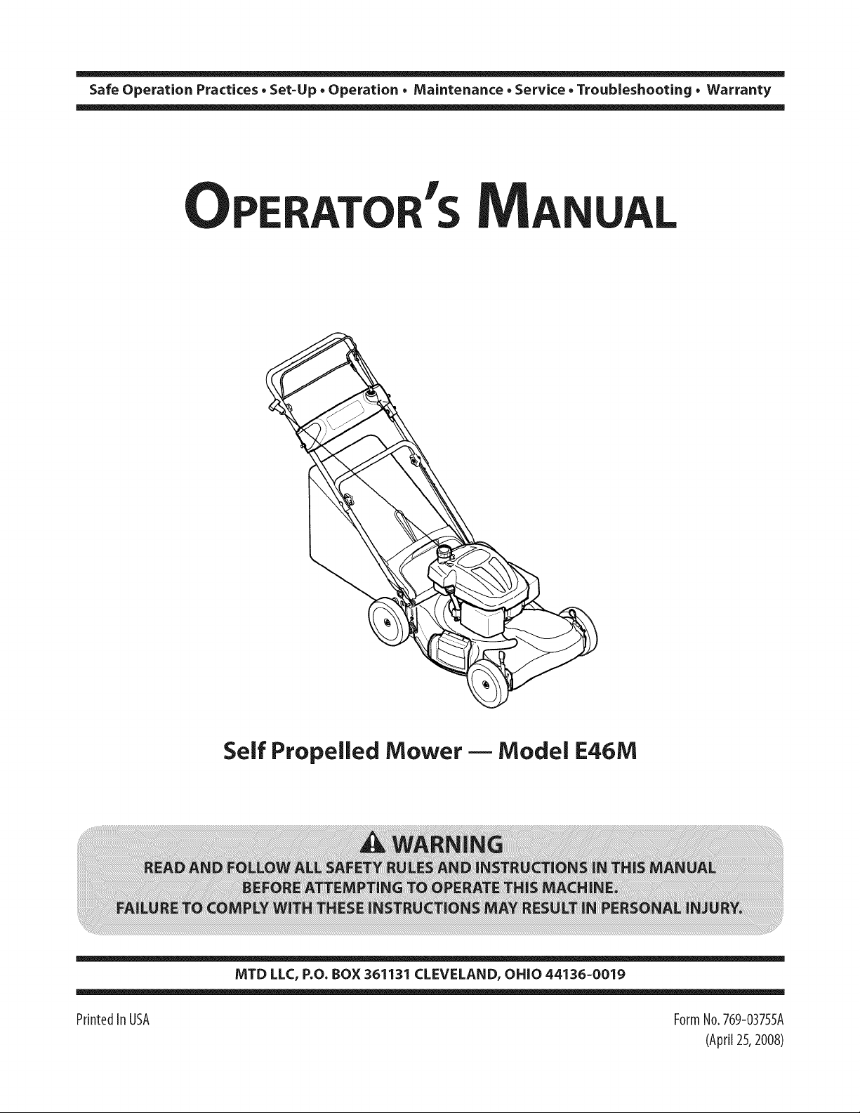
Self Propelled Mower m Model E46M
MTD LLC, P.O. BOX 361131 CLEVELAND, OHiO 44136-0019
PrintedIn USA FormNo.769-03755A
(April25,2008)
Page 2
ToTheOwner
ThankYou
1
Thank you for purchasing a Lawn Mower manufactured by
MTD LLC. It was carefully engineered to provide excellent
performance when properly operated and maintained.
Please read this entire manual prior to operating the equipment.
It instructs you how to safely and easily set up, operate and
maintain your machine. Please be sure that you, and any other
persons who will operate the machine, carefully follow the
recommended safety practices at all times. Failure to do so could
result in personal injury or property damage.
All information in this manual is relative to the most recent
product information available at the time of printing. Review
this manual frequently to familiarize yourself with the machine,
its features and operation. Please be aware that this Operator's
Manual may cover a range of product specifications for various
models. Characteristics and features discussed and/or illustrated
in this manual may not be applicable to all models. MTD LLC
reserves the right to change product specifications, designs and
equipment without notice and without incurring obligation.
Table of Contents
Safe Operation Practices ........................................ 3
Assembly & Set-Up .................................................. 8
Controls & Features ................................................ 11
Operation ................................................................ 12
Maintenance &Adjustment. ................................. 13
This product has met the rigid safety standards of the Outdoor
Power Equipment Institute and an independent testing
laboratory. If you have any problems or questions concerning
the machine, phone your local authorized MTD service dealer
or contact us directly. MTD's Customer Support telephone
numbers, website address and mailing address can be found on
this page. We want to ensure your complete satisfaction at all
times.
Throughout this manual, all references to right and left side of the
machine are observed from the operating position
The engine manufacturer is responsible for all engine-related
issues with regards to performance, power-rating, specifications,
warranty and service. Please refer to the engine manufacturer's
Owner's/Operator's Manual, packed separately with your
machine, for more information.
Service ..................................................................... 15
Troubleshooting ..................................................... 19
Engine Operation ................................................... 21
Engine Maintenance ............................................. 23
Illustrated Parts List .............................................. 28
RecordProductInformation
Before setting up and operating your new equipment, please
locate the model plate on the equipment and record the
information in the provided area to the right. You can locate the
model plate by standing at the operator's position and looking
down at the rear of the deck. This information will be necessary,
should you seek technical support via our web site, Customer
Support Department, or with a local authorized service dealer.
MODEL NUMBER
DIqFIIqFIIqFIIqFIIqD
SERIALNUMBER
DIqFllqFllqFllqNIqD
CustomerSupport
Please do NOT return the machine to the retailer or dealer without first contacting our Customer Support Department.
If you have difficulty assembling this product or have any questions regarding the controls, operation, or maintenance of
this machine, you can seek help from the experts. Choose from the options below:
0 Visit us on the web at www.mtdproducts.com
0 Call a Customer Support Representative at (800) 800-7:310 or (330) 220-468:3
0 Write us at MTD LLC • RO. Box :3611:31 • Cleveland, OH • 441:36-0019
Page 3
importantSafeOperationPractices
WARNING: This symbol points out important safety instructions which, if not followed,
could endanger the personal safety and/or property of yourself and others. Read and follow
all instructions in this manual before attempting to operate this machine. Failure to comply
with these instructions may result in personal injury.
When you see this symbol. HEED ITS WARNING!
CALIFORNIA PROPOSITION 65
WARNING: Engine Exhaust, some of its constituents, and certain vehicle components
contain or emit chemicals known to State of California to cause cancer and birth defects
or other reproductive harm.
WARNING: Battery posts, terminals, and related accessories contain lead and lead
,A
compounds, chemicals known to the State of California to cause cancer and reproductive
harm. Wash hands after handling.
DANGER: This machine was built to be operated according to the safe operation practices in
this manual. As with any type of power equipment, carelessness or error on the part of the
operator can result in serious injury. This machine is capable of amputating fingers, hands,
toes and feet and throwing objects. Failure to observe the following safety instructions could
result in serious injury or death.
2
GeneralOperation
1. Read this operator's manual carefully in its entirety before
attempting to assemble this machine. Read, understand,
and follow all instructions on the machine and in the
manuals) before operation. Keep this manual in a safe
place for future and regular reference and for ordering
replacement parts
2. Be completely familiar with the controls and the proper use
of this machine before operating it.
3. This machine is a precision piece of power equipment,
not a plaything. Therefore, exercise extreme caution at all
times. This machine has been designed to perform one job:
to mow grass. Do not use it for any other purpose.
4. Never allow children under 14 years of age to operate this
machine. Children 14 and over should read and understand
the instructions and safe operation practices in this manual
and on the machine and should be trained and supervised
by an adult.
5. Only responsible individuals who are familiar with these
rules of safe operation should be allowed to use this
machine.
6. Thoroughly inspect the area where the equipment is to be
used. Remove all stones, sticks, wire, bones, toys and other
foreign objects, which could be tripped over or picked up
and thrown by the blade. Thrown objects can cause serious
personal injury.
7. Plan your mowing pattern to avoid discharge of material
toward roads, sidewalks, bystanders and the like. Also,
avoid discharging material against a wall or obstruction,
which may cause discharged material to ricochet back
toward the operator.
8. To help avoid blade contact or a thrown object injury,
stay in operator zone behind handles and keep children,
bystanders, helpers and pets at least 75 feet from mower
while it is in operation. Stop machine if anyone enters area.
9. Always wear safety glasses or safety goggles during
operation and while performing an adjustment or repair
to protect your eyes. Thrown objects which ricochet can
cause serious injury to the eyes.
10. Wear sturdy, rough-soled work shoes and close-fitting
slacks and shirts. Shirts and pants that cover the arms
and legs and steel-toed shoes are recommended. Never
operate this machine in bare feet, sandals, slippery or light-
weight (e.g. canvas) shoes.
11. Do not put hands or feet near rotating parts or under the
cutting deck. Contact with blade can amputate fingers,
hands, toes and feet.
Page 4
12. Amissingordamageddischargecovercancauseblade 27.
contactorthrownobjectinjuries.
13. Manyinjuriesoccurasaresultofthemowerbeingpulled
overthefootduringafallcausedbyslippingortripping.
Donotholdontothemowerifyouarefalling;releasethe
handleimmediately. 28.
14. Neverpullthemowerbacktowardyouwhileyouare
walking.Ifyoumustbackthemowerawayfromawallor
obstructionfirstlookdownandbehindtoavoidtripping
andthenfollowthesesteps:
a. Stepbackfrommowertofullyextendyourarms.
b. Besureyouarewellbalancedwithsurefooting.
c. Pullthemowerbackslowly,nomorethanhalfway
towardyou.
Slope Operation
Slopes are a major factor related to slip and fall accidents, which
can result in severe injury. Operation on slopes requires extra
caution. If you feel uneasy on a slope, do not mow it. For your
safety, use the slope gauge included as part of this manual to
measure slopes before operating this machine on a sloped or
hilly area. If the slope is greater than 15 degrees, do not mow it.
d. Repeatthesestepsasneeded.
15. Do not operate the mower while under the influence of
alcohol or drugs. 1.
16. Do not engage the self-propelled mechanism on machines
so equipped while starting engine. 2.
17. The blade control handle is a safety device. Never attempt
to bypass its operation. Doing so makes the safety device
inoperative and may result in personal injury through 3.
contact with the rotating blade. The blade control handle
must operate easily in both directions and automatically
return to the disengaged position when released.
18. Never operate the mower in wet grass. Always be sure of Do Not:
your footing. A slip and fall can cause serious personal
injury. If you feel you are losing your footing, release the
blade control handle immediately and the blade will stop
rotating within three seconds.
19.
Mow only in daylight or good artificial light. Walk, never
run.
20.
Stop the blade when crossing gravel drives, walks or roads.
21.
If the equipment should start to vibrate abnormally, stop
the engine and check immediately for the cause. Vibration
is generally a warning of trouble.
22.
Shut the engine off and wait until the blade comes to
acomplete stop before removing the grasscatcher or
unclogging the chute. The cutting blade continues to
rotate for afew seconds after the blade control is released.
Never place any part of the body in the blade area until you
are sure the blade hasstopped rotating.
23.
Never operate mower without proper trail shield, discharge
cover, grasscatcher, blade control handle or other safety
protective devices in place and working. Never operate
mower with damaged safety devices. Failure to do socan
result in personal injury.
24.
Muffler and engine become hot and can causea burn. Do
not touch.
25.
Never attempt to make a wheel or cutting height
adjustment while the engine is running.
26.
Only use parts and accessories made for this machine by
the manufacturer. Failure to do so can result in personal
injury.
Do:
1. Do not mow near drop-offs, ditches or embankments, you
2. Do not mow slopes greater than 15 degrees asshown on
3. Do not mow on wet grass.Unstable footing could cause
Children
Tragic accidents can occur if the operator is not alert to the
presence of children. Children are often attracted to the mower
and the mowing activity. They do not understand the dangers.
Never assume that children will remain where you last saw them.
1.
2.
3.
4.
5.
6.
When starting engine, pull cord slowly until resistance
is felt, then pull rapidly. Rapid retraction of starter cord
(kickback) will pull hand and arm toward engine faster than
you can let go. Broken bones, fractures, bruises or sprains
could result.
If situations occur which are not covered in this manual,
use care and good judgement. Contact Customer Support
for assistance or the name of the nearest service dealer.
Mow across the face of slopes; never up and down. Exercise
extreme caution when changing direction on slopes.
Watch for holes, ruts, rocks, hidden objects, or bumps
which can cause you to slip or trip. Tall grass can hide
obstacles.
Always be sure of your footing. A slip and fall can cause
serious personal injury. If you feel you are losing your
balance, release the blade control handle immediately and
the blade will stop rotating within three (3) seconds.
could lose your footing or balance.
the slope gauge.
slipping.
Keep children out of the mowing area and under watchful
care of a responsible adult other than the operator.
Be alert and turn mower off if a child enters the area.
Before and while moving backwards, look behind and
down for small children.
Use extreme care when approaching blind corners,
doorways, shrubs, trees, or other objects that may obscure
your vision of a child who may run into the mower.
Keep children away from hot or running engines. They can
suffer burns from a hot muffler.
Never allow children under 14 years of age to operate this
machine. Children 14 and over should read and understand
the instructions and safe operation practices in this manual
and on the machine and be trained and supervised by an
adult.
4 I SECTION 2 -- IMPORTANT SAFE OPERATION PRACTICES
Page 5
Service
SafeHandling OfGas01ine:
I. To avoid personal injury or property damage use extreme
care in handling gasoline. Gasoline is extremely flammable
and the vapors are explosive. Serious personal injury can
occur when gasoline is spilled on yourself or your clothes,
which can ignite. Wash your skin and change clothes
immediately.
2. Use only an approved gasoline container.
3. Never fill containers inside a vehicle or on a truck or trailer
bed with a plastic liner. Always place containers on the
ground away from your vehicle before filling.
4. Remove gas-powered equipment from the truck or
trailer and refuel it on the ground. If this is not possible,
then refuel such equipment on a trailer with a portable
container, rather than from a gasoline dispenser nozzle.
5. Keep the nozzle in contact with the rim of the fuel tank or
container opening at all times until fueling is complete. Do
not use a nozzle lock-open device.
6.
Extinguish all cigarettes, cigars, pipes and other sources
of ignition.
7.
Never fuel machine indoors because flammable vapors will
accumulate in the area.
8.
Never remove gas cap or add fuel while engine is hot or
running. Allow engine to cool at least two minutes before
refueling.
9. Never overfill fuel tank. Filltankto no more than I inch
below bottom of filler neck to provide for fuel expansion.
I0. Replace gasoline cap and tighten securely.
1I. If gasoline is spilled, wipe it off the engine and equipment.
Move machine to another area. Wait 5 minutes before
starting engine.
12. Never store the machine or fuel container near an open
flame, spark or pilot light as on a water heater, space
heater, furnace, clothes dryer or other gas appliances.
13. To reduce fire hazard, keep machine free of grass, leaves,
or other debris build-up. Clean up oil or fuel spillage and
remove any fuel soaked debris.
14. Allow machine to cool at least 5 minutes before storing.
GeneralService:
I. Never run an engine indoors or in a poorly ventilated area.
Engine exhaust contains carbon monoxide, an odorless
and deadly gas.
2. Before cleaning, repairing, or inspecting, make certain the
blade and all moving parts have stopped. Disconnect the
spark plug wire and ground against the engine to prevent
unintended starting.
3. Check the blade and engine mounting bolts at frequent
intervals for proper tightness. Also, visually inspect blade
for damage (e.g., bent, cracked, worn) Replace blade with
the original equipment manufacture's (O.E.M.) blade only,
listed in this manual. "Use of parts which do not meet the
original equipment specifications may lead to improper
performance and compromise safety!"
4. Mower blades are sharp and can cut. Wrap the blade or
wear gloves, and use extra caution when servicing them.
5. Keep all nuts, bolts, and screws tight to be sure the
equipment is in safe working condition.
6. Never tamper with safety devices. Check their proper
operation regularly.
7. After striking a foreign object, stop the engine, disconnect
the spark plug wire and ground against the engine.
Thoroughly inspect the mower for any damage. Repair the
damage before starting and operating the mower.
8. Never attempt to make a wheel or cutting height
adjustment while the engine is running.
9. Grass catcher components, discharge cover, and trail shield
are subject to wear and damage which could expose
moving parts or allow objects to be thrown. For safety
protection, frequently check components and replace
immediately with original equipment manufacturer's
(O.E.M.) parts only, listed in this manual. "Use of parts
which do not meet the original equipment specifications
may lead to improper performance and compromise
safety!"
10. Do not change the engine's governor setting or over-speed
the engine. The governor controls the maximum safe
operating speed of the engine.
11. Check fuel line, tank, cap, and fittings frequently for cracks
or leaks. Replace if necessary.
12. Do not crank engine with spark plug removed.
13. Maintain or replace safety and instruction labels, as
necessary.
14. Observe proper disposal laws and regulations. Improper
disposal of fluids and materials can harm the environment.
15. According to the Consumer Products Safety Commission
(CPSC) and the U.S. Environmental Protection Agency (EPA),
this product has an Average Useful Life of seven (7) years,
or 140 hours of operation. At the end of the Average Useful
Life have the machine inspected annually by an authorized
service dealer to ensure that all mechanical and safety
systems are working properly and not worn excessively.
Failure to do so can result in accidents, injuries or death
Donot modify engine
To avoid serious injury or death, do not modify engine in any
way. Tampering with the governor setting can lead to a runaway
engine and cause it to operate at unsafe speeds. Never tamper
with factory setting of engine governor.
SECTION 2 -- IMPORTANT SAFE OPERATION PRACTICES S
Page 6
Notice Regarding Emissions
Engines which are certified to comply with California and federal
EPA emission regulations for SORE (Small Off Road Equipment)
are certified to operate on regular unleaded gasoline, and
may include the following emission control systems: Engine
Modification (EM), Oxidizing Catalyst (OC), Secondary Air
Injection (SAI) and Three Way Catalyst (TWC) if so equipped.
SparkArrestor
_hlll ARNING: This machine is equipped with an
effective working order by the operator. In the State of California
the above is required by law (Section 4442 of the California
Public Resources Code). Other states may have similar laws.
Federal laws apply on federal lands.
A spark attester for the muffler is available through your
nearest engine authorized service dealer or contact the service
department, RO. Box 361131 Cleveland, Ohio 44136-0019.
internal combustion engine and should not be used
on or near any unimproved forest-covered, brush
covered or grass-covered land unless the engine's
exhaust system is equipped with a spark arrester
meeting applicable local or state laws (if any).
If a spark arrester is used, it should be maintained in
WARNING: Your Responsibility--Restrict the use of this power machine to persons who read, understand and
follow the warnings and instructions in this manual and on the machine.
6 I SECTION 2 -- IMPORTANT SAFE OPERATION PRACTICES
SAVETHESEINSTRUCTIONS!
Page 7
or a corner of a building...
!
|
I-
v
Z
0
0
!--
Z
Q.
I
¢N
Z
o
I-
15 °
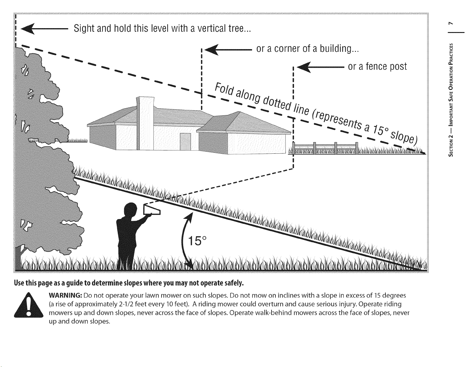
Usethis page as a guide to determine slopeswhere you may not operate safely,
WARNING: Do not operate your lawn mower on such slopes. Do not mow on inclines with a slope in excess of 15 degrees
(a rise of approximately 2-1/2 feet every 10 feet). A riding mower could overturn and cause serious injury. Operate riding
mowers up and down slopes, never across the face of slopes. Operate walk-behind mowers across the face of slopes, never
up and down slopes.
Page 8
AssembJy& Set-Up
Contents of Carton
3
One Lawn Mower
One Grass Catcher
One Lawn Mower Operator's Manual
One Side Discharge Chute
Assembly
NOTE:This unit is shipped without gasoline or oil in the engine.
Fill up gasoline and oil as instructed in the accompanying engine
manual BEFORE operating your mower.
Handle
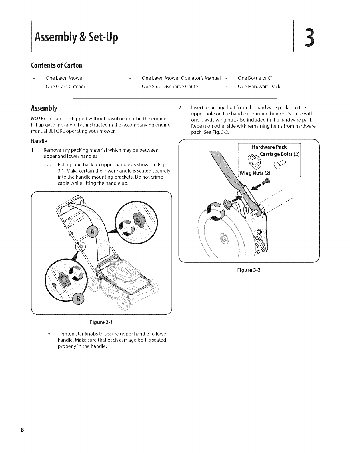
1.
Remove any packing material which may be between
upper and lower handles.
a. Pull up and back on upper handle as shown in Fig.
3-1. Make certain the lower handle is seated securely
into the handle mounting brackets. Do not crimp
cable while lifting the handle up.
One Bottle of Oil
One Hardware Pack
2.
Insert a carriage bolt from the hardware pack into the
upper hole on the handle mounting bracket. Secure with
one plastic wing nut, also included in the hardware pack.
Repeat on other side with remaining items from hardware
pack. See Fig. 3-2.
f
Hardware Pack
_Carria g_olts (2)
Wing Nuts (2)
Figure 3-1
b. Tighten star knobs to secure upper handle to lower
handle. Make sure that each carriage bolt is seated
properly in the handle.
Figure 3-2
Page 9
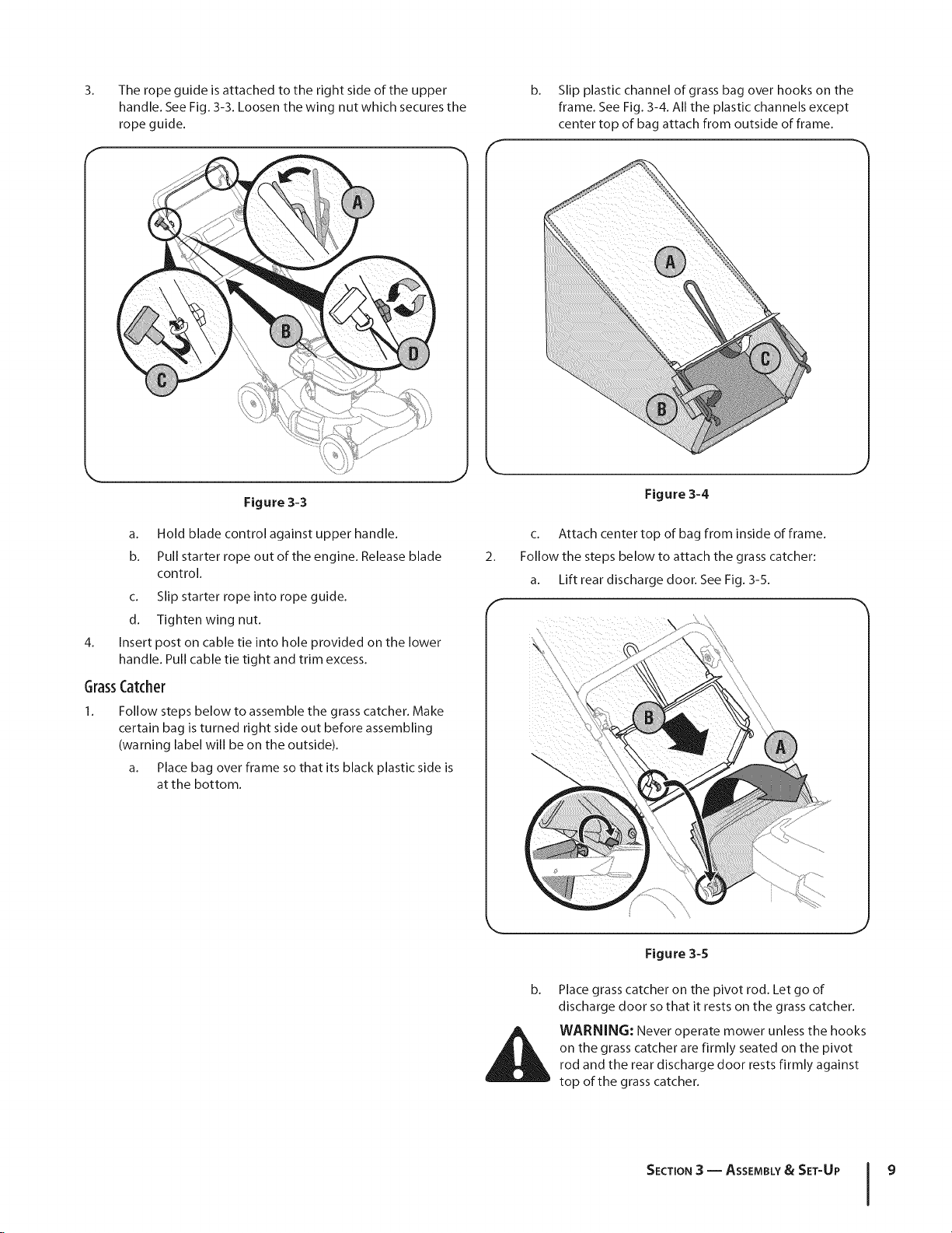
3.
The rope guide is attached to the right side of the upper
handle. See Fig. 3-3. Loosen the wing nut which secures the
rope guide.
b.
Slip plastic channel of grass bag over hooks on the
frame. See Fig. 3-4. All the plastic channels except
center top of bag attach from outside of frame.
F
Figure 3-3
a. Hold blade control against upper handle.
b. Pull starter rope out of the engine. Release blade
control.
c. Slip starter rope into rope guide.
d. Tighten wing nut.
4.
Insert post on cable tie into hole provided on the lower
handle. Pull cable tie tight and trim excess.
GrassCatcher
1.
Follow steps below to assemble the grass catcher. Make
certain bag is turned right side out before assembling
(warning label will be on the outside).
a. Place bag over fra me so that its black plastic side is
at the bottom.
Figure 3-4
c. Attach center top of bag from inside of frame.
2.
Follow the steps below to attach the grass catcher:
a. Lift rear discharge door. See Fig. 3-5.
F
Figure 3-5
Place grass catcher on the pivot rod. Let go of
discharge door so that it rests on the grass catcher.
WARNING: Never operate mower unless the hooks
on the grass catcher are firmly seated on the pivot
rod and the rear discharge door rests firmly against
top of the grass catcher.
SECTION 3 -- ASSEMBLY& SET-UP 9
Page 10
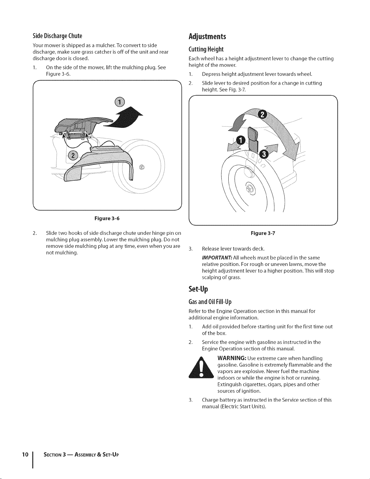
SideDischargeChute
Your mower is shipped as a mulcher. To convert to side
discharge, make sure grass catcher is off of the unit and rear
discharge door is closed.
1. On the side of the mower, lift the mulching plug. See
Figure 3-6.
Adjustments
CuttingHeight
Each wheel has a height adjustment lever to change the cutting
height of the mower.
1. Depress height adjustment lever towards wheel.
2. Slide lever to desired position for a change in cutting
height. See Fig. 3-7.
Figure 3-6
2_
Slide two hooks of side discharge chute under hinge pin on
mulching plug assembly. Lower the mulching plug. Do not
remove side mulching plug at any time, even when you are
not mulching.
Figure 3-7
3. Release lever towards deck.
IMPORTANT:All wheels must be placed in the same
relative position. For rough or uneven lawns, move the
height adjustment lever to a higher position. This will stop
scalping of grass.
Set-Lip
Gasand OilFill-Up
Refer to the Engine Operation section in this manual for
additional engine information.
1. Add oil provided before starting unit for the first time out
of the box.
2. Service the engine with gasoline as instructed in the
Engine Operation section of this manual.
gasoline. Gasoline is extremely flammable and the
_ WARNING: Use extreme care when handling
3. Charge battery as instructed in the Service section of this
vapors are explosive. Never fuel the machine
indoors or while the engine is hot or running.
Extinguish cigarettes, cigars, pipes and other
sources of ignition.
manual (Electric Start Units).
,J
SECTION 3 -- ASSEMBLY& SET-UP
Page 11
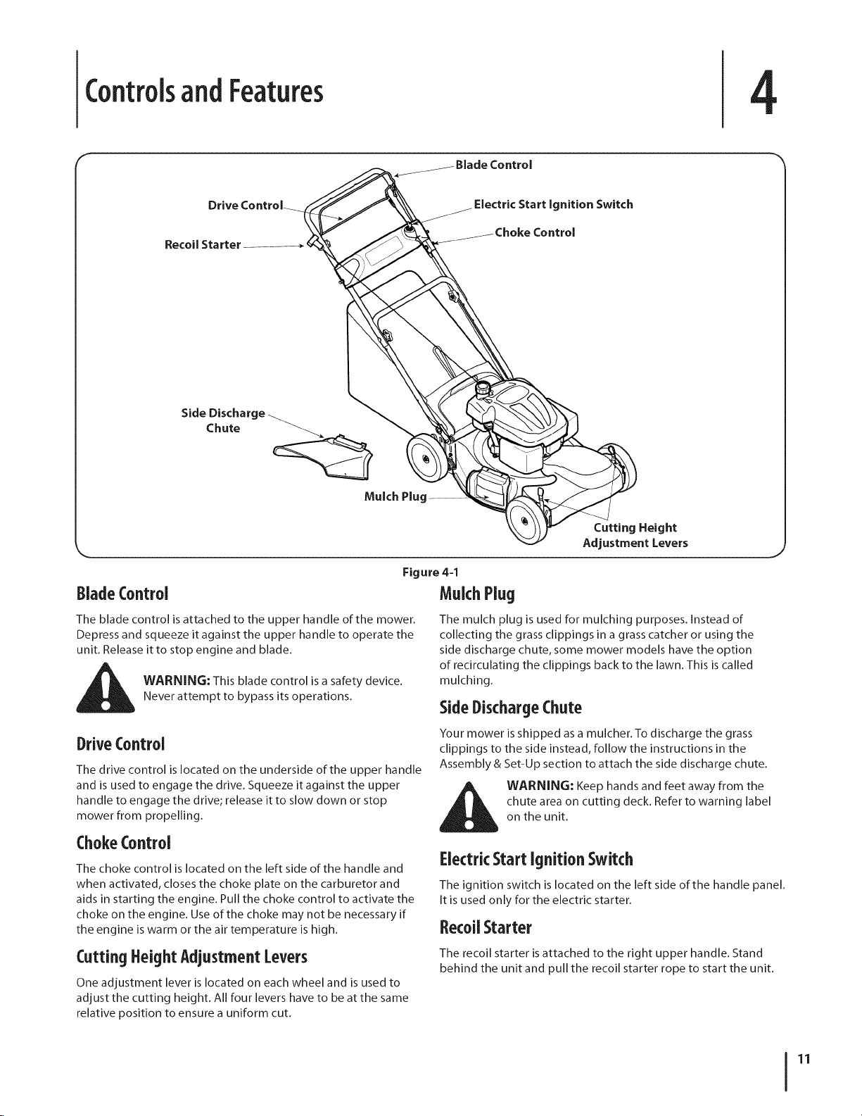
ControlsandFeatures
4
Drive Controk
Recoil Starter
Side Discharge
Chute
Mulch Pluq
. /
Figure 4=1
Electric Start ignition Switch
Control
Cutting Height
Adjustment Levers
BladeControl MulchPlug
The blade control is attached to the upper handle of the mower.
Depress and squeeze it against the upper handle to operate the
unit. Release it to stop engine and blade.
_ ARNING: This blade control is a safety device.
Never attempt to bypass its operations.
The mulch plug is used for mulching purposes. Instead of
collecting the grass clippings in a grass catcher or using the
side discharge chute, some mower models have the option
of recirculating the clippings back to the lawn. This is called
mulching.
SideDischargeChute
DriveControl
The drive control is located on the underside of the upper handle
and is used to engage the drive. Squeeze it against the upper
handle to engage the drive; release it to slow down or stop
mower from propelling.
Your mower is shipped as a mulcher. To discharge the grass
clippings to the side instead, follow the instructions in the
Assembly & Set-Up section to attach the side discharge chute.
chute area on cutting deck. Refer to warning label
_hb ARNING: Keep hands and feet away from the
on the unit.
ChokeControl
The choke control is located on the left side of the handle and
when activated, closes the choke plate on the carburetor and
aids in starting the engine. Pull the choke control to activate the
choke on the engine. Use of the choke may not be necessary if
the engine is warm or the air temperature is high.
Cutting HeightAdjustmentLevers
One adjustment lever is located on each wheel and is used to
adjust the cutting height. All four levers have to be at the same
relative position to ensure a uniform cut.
ElectricStartIgnition Switch
The ignition switch is located on the left side of the handle panel.
It is used only for the electric starter.
RecoilStarter
The recoil starter is attached to the right upper handle. Stand
behind the unit and pull the recoil starter rope to start the unit.
11
Page 12

Operation
Starting Engine
WARNING: Be sure no one other than the operator
isstanding near the lawn mower while starting
engine or operating mower. Never run engine
indoors or in enclosed, poorly ventilated areas.
Engine exhaust contains carbon monoxide, an
odorless and deadly gas. Keep hands, feet, hair and
loose clothing away from any moving parts on
engine and lawn mower.
Pull out the choke knob located on the left side of the
upper handle. See Fig. 5-1.
NOTE:Use of the choke may not be necessary if the engine
iswarm or the air temperature is high.
2_
Standing behind the mower, squeeze and hold the blade
control against upper handle.
3.
Recoil Start: Pull the recoil starter lightly until resistance
isfelt, then pull rapidly to overcome compression, prevent
kickback, and start the engine. Repeat if necessary. See Fig.
5-1.
NOTE: Do not allow the recoil starter to snap back against
the rope guide.
Electric Start: Turn ignition key to the right to start the
engine. Release the key after the engine starts. See Fig. 5-1.
4_
When engine warms up, push in the choke knob.
Stopping Engine
1. Release blade control to stop the engine and blade.
before performing any work on the mower or to
WARNING: Wait for the blade to stop completely
remove the grasscatcher.
UsingYourlawn Mower
Be sure lawn is clear of stones, sticks, wire, or other objects
which could damage lawn mower or engine. Such objects could
be accidently thrown by the mower in any direction and cause
serious personal injury to the operator and others.
1. Once the engine is running, squeeze the drive control
against the upper handle to propel mower.
WARNING: The operation of any lawn mower can
result in foreign objects being thrown into the eyes,
which can damage your eyes severely. Always wear
safety glasses while operating the mower, or while
performing any adjustments or repairs on it.
F
(
Figure 5-1
UsingGrassCatcher
You can use the grass catcher to collect clippings while you are
operating the mower.
1. Attach grass catcher following instructions in the
"Assembly & Set-Up" section. Grass clippings will
automatically collect in bag as you run mower. Operate
mower till grass bag is full.
2. Stop engine completely by releasing the blade control.
Make sure that the unit has come to a complete stop.
3. Lift discharge door and pull grass bag up and away from
the mower to remove the bag. Dispose of the grass
clippings and reinstall the bag when complete.
WARNING: If you strike a foreign object, stop the
engine. Remove wire from the spark plug,
thoroughly inspect mower for any damage, and
repair damage before restarting and operating.
Extensive vibration of mower during operation is an
indication of damage. The unit should be promptly
inspected and repaired.
UsingasMulcher
For mulching grass, remove the grass catcher and side discharge
chute from the mower. For effective mulching, do not cut wet
grass. If the grass has been allowed to grow in excess of four
inches, mulching is not recommended. Use the grass catcher to
bag clippings instead.
Page 13

Maintenance&Adjustments
Maintenance
GeneralRecommendations
Always observe safety rules when performing any
maintenance.
The warranty on this lawn mower does not cover items that
have been subjected to operator abuse or negligence. To
receive full value from warranty, operator must maintain
the lawn mower as instructed here.
Changing of engine-governed speed will void engine
wa rra nty.
All adjustments should be checked at least once each
season.
Periodically check all fasteners and make sure these are
tight.
WARNING: Always stop engine, disconnect spark
plug, and ground against engine before performing
any type of maintenance on your machine.
Lubrication
1.
Lubricate pivot points on the blade and drive controls
at least once a season with light oil. These controls must
operate freely in both directions. See Fig. 6-1.
2. Lubricate the wheels at least once a season with light oil (or
motor oil). If wheels are removed for any reason, lubricate
surface of the pivot arm and inner surface of the wheel
with light oil. See Fig. 6-1.
3. Lubricate the torsion spring and pivot points on the rear
discharge door and side mulch plug periodically with light
oil to prevent rust. See Fig. 6-1.
4. The transmission is pre-lubricated and sealed at the factory
and does not require lubrication.
5. Follow the Engine Maintenance section for lubrication
schedule and instruction for engine lubrication.
DeckCare
Clean underside of the mower deck after each use to prevent
build-up of grass clippings or other debris. Follow steps below
for this job.
1. Disconnect spark plug wire. Drain gasoline from lawn
mower or place a piece of plastic under the gas cap.
2. Tip mower so that it rests on the housing. Keep the side
with the air cleaner facing up. Hold mower firmly.
any direction and do not leave the mower tipped for
WARNING: Never tip the mower more than 90° in
any length of time. Oil can drain into the upper part
of the engine causing a starting problem.
3. Scrape and clean the underside of the deck with a suitable
tool. Do not spray with water.
IMPORTANT: Do not use a pressure washer or garden hose
to clean your unit. These may cause damage to bearings,
or the engine. The use of water will result in shortened life
and reduce serviceability.
4. Put the mower back on its wheels on the ground. Ifyou
had put plastic under the gas cap earlier, make sure to
remove it now.
Figure 6-1
13
Page 14

EngineCare
NOTE: Refer to the Engine Operation and Maintenance sections
in this manual for detailed instructions.
Maintain oil level.
Service air cleaner every 25 hours under normal conditions.
Clean every few hours under extremely dusty conditions.
Clean spark plug and reset the gap once a season.
Clean engine regularly with a cloth or brush. Keep the area
around the top of the engine clean to permit proper air
circulation. Remove all grass, dirt, and combustible debris
from muffler area.
ReplacingRearFlap
1. To remove rear flap, lift rear door, and press flap in on
either side to remove from hole. See Fig. 6-2.
r
\\
Figure 6=2
2.
Remove flap from opposite hole and replace with new flap
in the opposite order and manner of removal.
SECTION 6-- MAINTENANCE & ADJUSTMENTS
Page 15

Service
7
BladeCare
WARNING: When removing the cutting blade for
sharpening or replacement, protect your hands with
a pair of heavy gloves or use a heavy rag to hold the
blade.
Periodically inspect the blade adapter for cracks, especially if you
strike a foreign object. Replace when necessary. Follow the steps
below for blade service.
1. Disconnect spark plug boot from spark plug. Turn mower
on its side making sure that the air filter and the carburetor
are facing up.
2. Remove the bolt and the blade bell support which hold the
blade and the blade adapter to the engine crankshaft. See
Fig. 7-1.
5. Lubricate the engine crankshaft and the inner surface of
the blade adapter with light oil. Slide the blade adapter
onto the engine crankshaft. Place the blade on the adapter
such that the side of the blade marked "Bottom" (or with
part number) faces the ground when the mower is in the
operating position. Make sure that the blade is aligned and
seated on the blade adapter flanges.
6. Place blade bell support on the blade. Align notches on the
blade bell support with small holes in blade.
7. Replace hex bolt and tighten hex bolt to torque: 450 in. Ibs.
rain., 600 in. Ibs. max.
To ensure safe operation of your mower, periodically check the
blade bolt for correct torque.
Belt Care
Remove two shoulder screws securing front drive cover to
mower deck. See Figure 7-2. Press inward on sides of front
drive cover and release tabs that secure it to the height
adjuster brackets. Remove drive cover from mower.
r
Support
Figure 7-1
3. Remove blade and adapter from the crankshaft. See Fig.
7-1.
4.
Remove blade from the adapter for testing balance.
Balance the blade on a round shaft screwdriver to check.
Remove metal from the heavy side until it balances evenly.
When sharpening the blade, follow the original angle of
grind. Grind each cutting edge equally to keep the blade
balanced.
WARNING: An unbalanced blade will cause
excessive vibration when rotating at high speeds. It
may cause damage to mower and could break
causing personal injury.
\
Figure 7-2
2. Loosen screw holding belt tension spring to transmission.
See Figure 7-2 inset. Do not remove screw completely. As
you loosen it, tension on the belt will be released. Push
transmission up a little and slide belt offthe transmission
pulley.
3. Tip mower on its side with the air filter up to access belt
from underside of mower and remove blade as described
in the previous section. Refer to Fig. 7-1.
15
Page 16

4. Press inward on tab on the engine baffle to release it from
the baffle bracket. See Fig. 7-3.
Figure 7-3
5.
Slide belt off of engine pulley and thread through the
opening in the deck. See Figure 7-4.
6. Replace with new belt, making sure belt is firmly seated on
engine pulley while pulling from the other side and sliding
it around the transmission pulley.
7. Reattach engine baffle and reassemble blade as described
in the previous section.
8. Turn mower back over and make sure belt is seated on
the transmission pulley. Tighten screw loosened earlier to
secure belt tension spring to the transmission.
9. Reassemble front drive cover.
ReplacingBattery
may cause burns. Do not short circuit or mutilate
WARNING: Batteries contain sulfuric acid which
batteries in any way. Do not put batteries in fire as
these may burst or release toxic materials.
Loosen star knobs securing upper and lower handles and
carefully fold the upper handle down toward the lower
handle as shown in Fig. 7-5.
f
ii
Figure 7-5
2.
Remove the two screws securing battery cover to battery
housing and place them to the side. See Fig. 7-5.
3.
Open battery cover, remove positive and negative leads
from battery, remove and replace with new battery.
Figure 7-4
Connect the positive lead to the positive side of the battery
pack, then connect the negative side.
'°1
SECTION7-- SERVICE
Page 17

NOTE: The battery you have may differ slightly from the Charaina Battery
one shown in Fig. 7-6. Refer to the Parts List.
÷
Positive
Terminal
Negative I
Terminal
NOTE:The special designed plug on the charger will only fit into
the plug on the battery box.
1. Plug the battery charger into the port on the underside of
the battery housing. See Fig. 7-7.
f
Figure 7-6
IMPORTANT:When replacing battery pack in handle panel,
battery pack must be positioned with the positive terminal
to the left side and the negative terminal to the right side
of panel (Positive terminal is closest to the key switch).
See Fig. 7-6. Replacing battery pack incorrectly will cause
serious damage.
4.
Reattach battery cover to battery housing by securing with
the two screws removed earlier, making sure to snap the
wire conduit on the left into place on the housing.
5.
Fold handles back up and tighten star knobs.
and toxic material; handle with care and keep away
WARNING: The battery contains corrosive fluid
from children. Do not puncture, disassemble,
mutilate or incinerate the battery. Explosive gases
could be vented during charging or discharging. Use
in a well ventilated area, away from sources of
ignition.
Figure 7-7
2.
Insert the battery charger plug into a standard 120 volt
household outlet. Charge battery for 8 to 10 hours before
initial use. Do not charge longer than 12 hours.
NOTE: For optimal engine starting performance and
battery life, charge the battery after every use for 8 to 10
hours or until the green LED light illuminates (If equipped).
Do not charge longer than 12 hours.
3.
After charging, disconnect charger plug from outlet first,
then disconnect charger lead from battery.
IMPORTANT: Do not remove the battery pack from
the electric starter housing for any reason other than
replacement.
IMPORTANT: Always plug charger lead into battery pack
lead first, and then insert battery charger plug into 120
volt standard household outlet. Follow this order of action
every time you charge the battery.
SECTION7 -- SERVICE 17
Page 18

ReplacingFuse
The electric starter circuit and battery are protected by a 40
ampere fuse. If the fuse burns out, the electric starter will not
operate. If the unit fails to start with the electric starter, perform
the following steps to check the fuse inside the battery housing:
1. Open the battery cover as described in Replacing Battery.
See Fig. 7-5.
2. Remove fuse from socket and inspect as shown in Fig. 7-8.
If it is burned out, replace with standard automotive 40
ampere fuse.
Off-SeasonStorage
The following steps should be taken to prepare your lawn mower
for storage.
Clean and lubricate mower thoroughly as described in the
lubrication instructions.
Do not use a pressure washer or garden hose to clean your
unit.
Coat mower's cutting blade with chassis grease to prevent
rusting.
Refer to Engine Maintenance section for correct engine
storage instructions.
Store mower in a dry, clean area. Do not store next to
corrosive materials, such as fertilizer.
When storing any type of power equipment in a poorly
ventilated or metal storage shed, care should be taken to
rust-proof the equipment. Using a light oil or silicone, coat the
equipment, especially cables and all moving parts of your lawn
mower before storage.
Battery
The battery must be stored with a full charge. Extended storage
of a discharged battery will reduce life and capacity of the
battery.
Figure 7-8
3.
Carefully place wiring back into housing, close battery
cover, and fold upper handle back into place.
NOTE:The engine can be started manually if the fuse burns
out.
SECTION7-- SERVICE
Page 19

Troubleshooting
Problem
Engine Fails to start
1.
Blade control disengaged. 1.
2.
Spark plug boot disconnected. 2.
3.
Fuel tank empty or stale fuel. 3.
4.
Engine not primed (if equipped with primer). 4.
5. Faulty spark plug.
6. Blocked fuel line.
Z Engine flooded.
Cause
Remedy
Engage blade control.
Connect wire to spark boot.
Fill tank with clean, fresh gasoline.
Prime engine as instructed in the Operation
section.
5. Clean,adjust gap, or replace.
6. Cleanfuel line.
Z Waita few mmutes to restart, butdo not
prime.
B,
Fuel valve (if equipped) closed. 8.
9.
Engine not choked (if equipped with choke). 9.
10.
Burnt fuse. (Electric Start only)
Engine runs erratic
Engine overheats 1. Fill crankcase with proper oil.
Occasional skips 1. Adjust gap to .030".
(hesitates) at
high speed
Idles poorly Spark plug fouled, faulty, or gap too wide. 1.
Excessive Vibration Cutting blade loose or unbalanced. 1.
Mower will not
mulch grass
1.
Spark plug boot loose.
Blocked fuel line or stale fuel.
2.
3.
Vent in gas cap plugged.
4.
Water or dirt in fuel system.
5.
Dirty air cleaner.
6.
Unit running with CHOKE (if equipped)
applied.
1.
Engine oil level low.
2.
Air flow restricted.
1.
Spark plug gap too close.
1.
2.
Dirty air cleaner. 2.
1.
2.
Bent cutting blade. 2.
1, Wet grass. 1,
2, Excessivelyhigh grass. 2.
3. Dull blade. 3.
Open fuel valve. See engine manual.
Choke engine. See engine manual.
10.Replace fuse (see Service Section).
1. Connectand tighten spark plug boot.
2. Clean fuel line; fill tank with clean, fresh
gasoline.
3. Clear vent.
4. Drain fuel tank. Refill with fresh fuel.
5. Refertoengine manual.
6. Push CHOKE knob in.
2. Clean area around and on top of engine.
Reset gap to .030" or replace spark plug.
Refer to engine manual.
Tighten blade and adapter. Balance blade.
See an authorized service dealer.
Do not mow when grass is wet; wait until
later to cut.
Mow once ata high cutting height, then
mow again at desired height or make a
narrower cutting path.
Sharpen or replace blade.
Continued on next page
19
Page 20

Problem
Uneven cut 1. Wheels not positioned correctly. 1. Place all four wheels in same height position
2. Dull blade. 2. Sharpen or replace blade.
Cause Remedy
(if equipped with individual height adjusters).
i : ifo iii iJi
SECTION 8 -- TROUBLESHOOTING
Page 21

EngineOperation
Fuel Cap
Grip
Cap
\
Air Cleaner
Oil Drain
Mumer
Figure 10-1
Pre-OperationCheck
Oil Recommendations
NOTE:This engine is shipped without gasoline or oil in the
engine. Running the engine with insufficient oil can cause
serious engine damage and void the engine warranty.
Before starting engine, fill with oil. Do not over-fill. Oil
capacity is about 20 oz.
Use a 4-stroke, or an equivalent high detergent, premium
quality motor oil certified to meet or exceed U.S. automobile
manufacturer's requirements for service classification SG/SF.
Motor oils classified SG/SF will show this designation on the
container.
SAE 10W-30 is recommended for general, all temperature use. If
single viscosity oil is used, select the appropriate viscosity for the
average temperature in your area from the chart to the right.
Spark Plug
_ 20w
m__ 20
mlmlllmIilmllm
2ow4o, _ow5o_____
I
15w40, O_____m/b.
Q lOW40 Iilmmmmlll ml_lmmlmmmmmm
I v
lOw30_____u
m,3o
(°C)-30 o -20o -10° 0° 10° 20o 30o 40o
(°F)-20 ° 0° 20o 40o 60o 80o 100o
Ambient Temperature
1. Single Viscosity
2. Multi Viscosity
NOTE: Using non detergent oil or 2-stroke engine oil could
shorten the engine's service life.
21
Page 22

CheckOilLevel
NOTE: Be sure to check the engine on a level surface with the
engine stopped.
1. Remove the oil filler cap and wipe the dipstick clean. See
Fig. 10-2.
CheckFuelLevel
1. Clean around fuel fill before removing cap to fuel.
2. Fill tank to approximately 1-inch below lowest portion of
neck to allow for fuel expansion. Be careful not to overfill.
NOTE: Before refueling, allow engine to cool 2 minutes.
Starting TheEngine
Figure 10-2
2. Insertthe dipstickinto the oil filler neck, but do not screwit in.
3. Ifthelevelislow, slowlyadd oiltothe upperlimitonthedipstick.
See Fig. 10-2 inset.
4. Tighten dipstick firmly before starting engine.
NOTE: Do not overfill. Overfilling with oil may cause
smoking, hard starting, spark plug fouling, or oil saturation
of air cleaner.
_ ARNING: Always keep hands and feet clear of
1. Pull out the choke knob located on the left side of the upper
equipment moving parts. Do not use a pressurized
starting fluid. Vapors are flammable.
handle. See Fig. 10-3.
Figure 10-3
J
FuelRecommendations
Use automotive gasoline (unleaded or low leaded to minimize
combustion chamber deposits) with a minimum of 87 octane. 2.
Gasoline with up to 10% ethanol or 15% MTBE (Methyl Tertiary
Butyl Ether) can be used. Never use an oil/gasoline mixture, dirty 3.
gasoline, or gasoline over 30 days old. Avoid getting dirt, dust, or
water in the fuel tank. DO NOT USE E85 GASOLINE.
WARNING: Gasoline is extremely flammable and is
explosive under certain conditions. Refuel in a well-
ventilated area with the engine stopped. Do not
smoke or allow flames or sparks in the area where
the engine is refueled or where gasoline is stored.
Avoid repeated or prolonged contact with skin or
breathing of va pot.
WARNING: Do not overfill the fuel tank (there
should be no fuel in the filler neck). After refueling,
make sure the tank cap is closed properly and
securely. Be careful not to spill fuel when refueling.
Spilled fuel or fuel vapor may ignite. If any fuel is
spilled, make sure the area is dry before starting the
engine.
SECTION 9 -- ENGINE OPERATION
NOTE: Use of the choke may not be necessary if the engine
is warm or the air temperature is high.
Standing behind the mower, depress the blade control
handle and hold it against the upper handle.
Recoil Start: Pull the recoil starter lightly until resistance
is felt, then pull rapidly to overcome compression, prevent
kickback, and start the engine. Repeat if necessary. See Fig.
10-3.
NOTE: Do not allow the recoil starter to snap back against
the rope guide.
Electric Start: Turn ignition key to the right to start the
engine. Release the key after the engine starts. See Fig.
10-3.
4. When engine warms up, push in the choke knob.
StoppingTheEngine
1. Release the blade control.
Page 23

EngineMaintenance
_ ARNING: Shut offthe engine before performing
IMPORTANT: If engine must be tipped to transport equipment
or to inspect or remove grass, keep spark plug side of engine
up. Transporting or tipping engine spark plug down may cause
smoking, hard starting, spark plug fouling, or oil saturation of air
cleaner.
MaintenanceSchedule
any maintenance. To prevent accidental start-up,
disconnect the spark plug boot.
1
Periodic inspection and adjustment of the engine is essential
if high level performance is to be maintained. Regular
maintenance will also ensure a long service life. The required
service intervals and the kind of maintenance to be performed
are described in the table below. Follow the hourly or calendar
intervals, whichever occur first. More frequent service is required
when operating in adverse conditions.
_1 WARNING: If the engine has been running, the
muffler will be very hot. Be careful not to touch the
muffler.
FirstSHours
CheckEngineOilLevel
ChangeEngineOilff _/ _/
CheckAirCleaner M/
ServiceAirCleanerf M/
CheckSparkPlug V/
ReplaceSparkPlug V/
CleanEngineShroud V/
Cleanaroundmuffler V /
ReplaceFuelFilter M/
f Service more frequently when used in dusty areas.
ff Every season or 25 hours if operating under heavy load or high ambient temperature.
EachUseor
EveryS Hrs.
,/
EverySeason
or25 Hours
EverySeason
or SOHours
EverySeason
or 100Hours
Service
Dates
23
Page 24

OilService
AirCleanerService
Check oil level regularly.
Be sure correct oil level is maintained. Check every five
hours or daily before starting engine. See oil checking
procedure in the Operation section.
OilChange
IMPORTANT: Be sure to check engine on a level surface with the
engine stopped. Drain the oil while the engine is still warm to
assure rapid and complete draining.
1. Remove all fuel from tank by running engine until it stops
from lack of fuel.
2. Remove drain plug and allow oil to drain into a suitable
container. See Fig. 10-1.
Oil Fill Cap
Paper filters cannot be cleaned and must be replaced once a year
or every 100 operating hours; more often if used in extremely
dusty conditions.
_ WARNING: Never use gasoline or low flash point
IMPORTANT: Never run the engine without the air cleaner. Rapid
engine wear will result.
1. Remove the wing bolt and the air cleaner cover. Remove
solvents for cleaning the air cleaner element. A fire
or explosion could result.
the elements and separate them. See Fig. 10-2. Replace
paper element when dirty or damaged. Clean foam
element or replace when damaged.
f
Figure 10-1
i_ WARNING: Before tipping engine or equipment to
3. Reinstall the drain plug and tighten it securely.
4. Refill with the recommended oil (see Operation section)
5. Reinstall the oil fill cap securely.
IMPORTANT: Used motor oil may cause skin cancer if repeatedly
left in contact with the skin for prolonged periods. Although this
is unlikely unless you handle used oil on a daily basis, it is still
advisable to thoroughly wash your hands with soap and water as
soon as possible after handling used oil.
NOTE: Please dispose of used motor oil in a manner that is
compatible with the environment. We suggest you take it in a
sealed container to your local service station for reclamation. Do
not throw it in the trash or pour it on the ground.
drain oil, drain fuel from tank by running engine
until fuel tank is empty.
and check the oil level. See Fig. 10-1.
Foam Element
Figure 10=2
2. To clean foam element, separate it from the paper element
and wash in liquid detergent and water. Allow to dry
thoroughly before using. Do not oil the foam element.
SECTION10-- ENGINEMAINTENANCE
Page 25

SparkPlugService
_ WARNING: DO NOT check for spark with spark
To ensure proper engine operation, the spark plug must be
properly gapped and free of deposits.
1. Remove the spark plug boot and use a spark plug wrench
i_ WARNING: If the engine has been running, the
2. Visually inspect the spark plug. Discard the spark plug
plug removed. DO NOT crank engine with spark
plug removed.
to remove the plug. See Fig. 10-3.
Spark Plug
Figure 10=3
muffler will be very hot. Be careful not to touch the
muffler.
if there is apparent wear, or if the insulator is cracked or
chipped. Clean the spark plug with a wire brush if it is to be
reused.
3_
Measure the plug gap with a feeler gauge. Correct as
necessary by bending side electrode. See Fig. 10-4. The
gap should be setto 0.030 in.
Electrode
Figure 10-4
4_
Check that the spark plug washer is in good condition
and thread the spark plug in by hand to prevent cross-
threading.
5_
After the spark plug is seated, tighten with a spark plug
wrench to compress the washer.
NOTE:When installing a new spark plug, tighten 1/2 turn
after the spark plug seats to compress the washer. When
reinstalling a used spark plug, tighten 1/8-1/4 turn after the
spark plug seats to compress the washer.
IMPORTANT:The spark plug must be securely tightened.
An improperly tightened spark plug can become very hot
and may damage the engine.
SECTION10 -- ENGINE MAINTENANCE 2S
Page 26

FuelFilter Service
The fuel filter cannot be cleaned and must be replaced once a
year or every 100 operating hours; more often if run with old
gasoline.
1. Remove all fuel from tank by running engine until it stops
from lack of fuel.
2. Remove c-clamp from fuel line and remove fuel line from
tank outlet. See Fig. 10-5.
Storage
Engines stored between 30 and 90 days need to be treated with
a gasoline stabilizer and engines stored over 90 days need to be
drained of fuel to prevent deterioration and gum from forming
in fuel system or on essential carburetor parts. If the gasoline in
your engine deteriorates during storage, you may need to have
the carburetor, and other fuel system components, serviced or
replaced.
1. Remove all fuel from tank by running engine until it stops
from lack of fuel.
Figure 10-5
3. Pull out old fuel filter from tank outlet. Replace when dirty
or damaged.
4. Grasp new fuel filter from shouldered end and insert it
completely to the shoulder into the tank outlet. See Fig.
10-5 inset.
5. Replace fuel line and c-clamp.
CleanEngine
If the engine has been running, allow it to cool for at least half
an hour before cleaning. Periodically remove dirt build-up from
engine. Clean finger guard and around muffler. Clean with a
brush or compressed air.
IMPORTANT'. Do not spray engine with water to clean because
water could contaminate fuel. Using a garden hose or pressure
washing equipment can also force water into the air cleaner or
muffler opening. Water in the air cleaner will soak the paper
element, and water that passes through the element or muffler
can enter the cylinder, causing damage.
_i ARNING: Never leave engine unattended while
2.
3.
4.
5. Store in a clean, dry and well ventilated area away from any
6. If possible, also avoid storage areas with high humidity,
7. Keep the engine level in storage. Tilting can cause fuel or
running.
Change oil. See Oil Change section.
Remove spark plug and pour about 1/2 an ounce of engine
oil into cylinder. Replace spark plug and crank slowly to
distribute oil.
Clean debris from around engine, under finger guard, and
under, around and behind muffler. Touch upany damaged
paint, and coat other areas that may rust with a light film
of oil.
appliance that operates with a flame or pilot light, such
as a furnace, water heater, or clothes dryer. Also avoid any
area with a spark producing electric motor, or where power
tools are operated.
because that promotes rust and corrosion.
oil leakage.
Removing FromStorage
1.
Check your engine as described in the Pre-Operation
Check section of this manual.
2.
If the fuel was drained during storage preparation, fill the
tank with fresh gasoline. If you keep a container of gasoline
for refueling, make certain it contains only fresh fuel.
Gasoline oxidizes and deteriorates over time, causing hard
starting.
3.
If the cylinder was coated with oil during storage
preparation, the engine will smoke briefly at startup. This
is normal.
i_lk WARNING: Accumulation of debris around muffler
could cause a fire. Inspect and clean before every
use.
SECTION10-- ENGINE MAINTENANCE
Page 27

The EZ Start Promise
Provisions of Your Limited Warranty
Inaddition to the other terms and conditions of the Limited Warranty
applicable to your new mower, MTD LLC("MTD") hereby warrants
that your mower's engine will start on the first or second attempt by
an able-bodied adult (subject to the limitations described below) for
the duration of the manufacturer's limited warranty applicable to your .
product. Ifthe engine on your mower fails to conform to this limited
warranty, MTD will cover the cost of parts and labor associated with
any adjustments and/or repairs necessary to return your engine
to its warranted condition. In order to make aclaim under these
provisions of your warranty, you must bring the product and proof of
purchase to an authorized MTD service provider. In many cases,the
retailer who sold you your mower is not equipped to provide warranty
service, so please locate the authorized service dealer nearest you by
either calling the phone number provided in your Operators Manual or
looking up an authorized service dealer on-line at www.mtdproducts.
com.
Items and Conditions Not Covered
The EZStart Promise does not cover and/or apply to the following:
• Cost of regular maintenance service or parts, such asfilters, fuel,
lubricants, oil changes, spark plugs, air filter, bladesharpening,
worn blades, cable/linkage adjustments, or brake and clutch
adjustments
= Transportation costs to and from an authorized MTD service
provider
= Any engine used for commercial, rental, institutional, governmen-
tal, or non-residential applications
= Any product or part that has beenaltered or misused or required
replacement or repair dueto misuse, accidents, or lack of proper
maintenance
• Repairs necessary dueto improper battery care, electrical supply
irregularities, or failure to properly prepare the mower prior to any
period of non-use over three months
= Pickup and/or delivery charges
• Operational misuse, neglect, accidents, unauthorized repairs or
attempted repairs of the engine or its components by anyone other
than an authorized MTD service provider.
Repairs or adjustments to correct starting difficulties dueto any
of the following: failure to follow proper maintenance procedures
-- rotary mower blade striking an object -- contaminants in the
fuel system --improper fuel or fuel/oil mixture (consult your
Operator's Manual if in doubt) -- failure to drain the fuel system
prior to any period of non-use over three months.
Any starting problem which results from the use of inappropriate
fuels, lubricants, or additives.
e
Special conditions or circumstances that normally require more
than two pulls to start, specifically: 1) First start-up following your
initial purchase, 2) first time starts after extended period(s) of
non-use over one month or seasonal storage, 3) cool temperature
starts such as those found in early spring and lateautumn, and 4)
difficult starting that results from the operator's failure to follow
the proper starting procedures identified in the Operator's Manual.
If you arehaving difficulty starting your unit, please check the
Operator's Manual to ensure that you areusing the correct starting
procedures. This can savean unnecessary visit to a Service
Dealer.
Owner Responsibilities
You must maintain your mower (including its engine) byfollowing the
maintenance procedures and starting instructions described in the
Operator's Manual. Such routine maintenance, whether performed by
adealer or by you, is at your expense. In addition, please retain your
proof of purchase and service receipts as these may be requiredto
validate a claim.
General Conditions
An authorized MTD service provider using approved replacement
parts must perform all repairs covered bythe EZ Start Promise.
Repair by an MTD authorized service dealer is your sole remedy
under this warranty. MTD is not liable for indirect, incidental, or
consequential damages in connection with the use of the products
covered by these warranties, including any cost or expense of
providing substitute equipment or service during reasonable periods
of malfunction or non-use pending completion of repairs under this
warranty.
Some states do not allow exclusions of incidental or consequential
damages, or limitations on how long an implied warranty lasts, so
certain exclusions and limitations may not apply to you.
GDO0-100163 Rev.B
Page 28

ModelE46M
74
\
78
14
19
I
47
Page 29

ModelE46M
Ref I Part Number
NO,
I
1 747-1214
2 710-0599
3 736-0270
4 17032A
5 732-1014
6 618-04376A
7 747-1161A
8 749-1233D
9 731-04177
10 687-02055
11 747-0710
12 782-7551A
13 720-0279
14 720-04072
15 710-1205
16 746-04485
17 710-1174
18 732-04089A
19 726-0240
20 746-04380
21 710-0654A
22 746-04484
23 664-04027
24 710-1650
25 687-02347
26 710-1241
27 687-02194A
687-02193A
28 787-01278
29 731-04150C
30 712-0397
31 750-04595
32 710-0216
33 732-04090A
34 712-04065
35 731-05021A
36 782-5002B
37 754-0637A
38 736-0447
39 750-04594
40 748-04015A
41 742-0741
42 736-0524B
Description
Drive Control
TT Screw 1/4-20 x 0.5
Bell Washer.265 x 0.75
Deflector Chute Adapter
Torsion Spring
Transmission Assembly
Blade Control
Upper Handle
Chute Deflector
Mulch Plug Complete
Hinge Pin
Wheel Dust Cap
Handle Knob
Star Knob
Eye Bolt
Control Cable
Carriage Bolt 5/16-18 x 2.0
Torsion Spring - LH
Cable Tie
Choke Cable
Self-Tapping Sems Screw
Drive Cable
Grassbag
Shoulder Screw # 12 -24
Front Bearing Assembly
Screw, 1/4-15 x 1.000
Height Adjustment Ass'y - RH
Height Adjustment Ass'y - LH
21" Deck
Rear Baffle
Wing Nut
Slev. Spacer 1.4" Lg.
Hex Screw, 3/8-16 x.75
Torsion Spring - RH
Flange Lock Nut, 3/8-16
Transmission Cover
Front Baffle
V-Belt
Wave Washer
Sleeve Spacer 8.985" Lg.
One Piece Blade Adapter
21" Mulching Blade
Blade Bell Support
Ref
j Part Number Description
No,
43 687-02334
44 710-1257
45 749-0928A
46 732-1043
47 720-0426
48 731-05865
49 634-04100
50 710-04531
51 717-1762
717-1761
52 747-04080A
53 710-0703
54 716-0102
55 710-1652
56 687-02271A
687-02270A
57 715-0221
58 736-0474
59 687-02333
687-02332
60 732-04175
61 738-04266
62 734-04087
63 782-01298
782-01299
64 732-0706
732-0707
65 747-04587
66 731-05642
67 731-06029
68 787-01593
69 731-05401
70 710-04577
71 710-0606
72 712-04064
73 725-04329
74 629-04051
75 725-04347
76 710-1667A
77 725-0201
78 725-1276
79 728-0199
Pivot Plate Assembly
Hex Screw 3/8-24 x 2.50
Lower Handle
Belt Tension Spring
Adjustment Knob
Rear Discharge Door
Front Wheel
Screw, 1/4-20 x .390
Gear 14T RH FWD
Gear 14T LH FWD
Grass Bag Frame
Carriage Bolt 1/4-20
Snap Ring
TT Scr. w/Washer 1/4-20 x.625
Handle Bracket Assembly - RH
Handle Bracket Assembly - LH
Dowel Pin
Washer
Pivot Arm Assembly - RH
Pivot Arm Assembly - LH
Rear Spring Lever
Shoulder Scr.500 Dia. x.434
Rear Wheel
Height Adjuster Plate - RH
Height Adjuster Plate - LH
Front Lever- RH
Front Lever- LH
Pivot Rod
Rear Trailing Shield
Engine Baffle
Engine Baffle Bracket
Engine Shroud
Screw, Machine, M4-.7
Screw, 1/4-20 x 1.50
Nut, Flange Lock, 1/4-20
Battery Charger
Electric Start Harness Assembly
Key Switch
Screw, #10-16 x .750
Key
Battery
Rivet
29
Page 30

EngineModel- 2P70MO
6
30=
21=
@
! J I
_o
f\ 3-
lIi ,
_7
@
U
%
5 4
@
12
J
22
@@
16
Page 31

Ref
NO.
1.
2.
3.
4.
5.
6.
7.
8.
9.
10.
11.
12.
13.
14.
15.
16.
17.
18.
19.
20.
21.
22.
23.
24.
25.
26.
27.
28.
29.
30.
31.
32.
Part Number Description
751-10368
751-10855
751-10335
751-10334
751-10852
751-I0413
751-I0857
751-I0858
751-I0319
751-I0344
751-I0345
751-I0370
751-I0854
751-I0310
751-I0307
751-I0856
751-I0342
751-I0364
751-I0358
751-I0300
751-I0299
751-I0298
751-I0297
751-I0411
751-I0403
751-I0402
751-I0387
751-I0292
751-I0351
751-I0822
751-I0823
751-I0824
752Z2P70MO
751-10326
751-10870
751-I0416
751-I0417
Fuel Tank
Flywheel Shroud
Rubber Fuel Tank Mounting Washer
Oil Filler Tube Assembly
Dipstick Assembly
Cylinder Head Complete
Short Block Assembly
Stop Switch and Brake Assembly
Recoil Spring and Pulley Assembly
Push Rod Kit
Valve Kit
Oil Drain Plug and Washer Assembly
Ignition Coil
Carburetor Assembly
Flywheel Key
Air Cleaner Housing Assembly Complete
Muffler Stud Assembly
Fuel Line Kit- Inc. hoses, clamps &filter
Fuel Filter
Fuel Cap Assembly
Recoil Starter Assembly
Air Cleaner Kit
Air Cleaner Thumb Screw
Muffler Guard
Muffler
Muffler Gasket/Heat Shield
Governor Return Spring
Spark Plug
Spark Arrestor
Electric Starter
Relay Assembly
Relay Harness Connector
Engine - Complete
Carburetor Kit - Major
Cylinder Head Service Kit
Gasket Kit - Complete
Gasket Kit - External
EngineModel- 2P70M0
NOTE: Illustrated parts without a numeric call-out are not servicable components.
31
Page 32

MTD CONSUMER GROUP (MTD) and the United States Environment Protection Agency (U. S. EPA)
Emission Control System Warranty Statement
(Owner's Defect Warranty Rights and Obligations)
TheU.S. EPAand MTDarepleasedtoexplaintheemissionscontrolsystemwarrantyonyourmodelyear2005andlatersmalloff-roadengine.
Newsmalloff-roadenginesmustbe designed,builtandequippedtomeetthe stringentanti-smogstandards.MTDmustwarrantytheemission
controlsystemonyour engineforthe periodoftimelistedbelow,providedtherehasbeennoabuse,neglectorimpropermaintenanceof yoursmall
off-roadengine.
Youremissioncontrolsystemmayincludepartssuchas thecarburetor,aircleaner,ignitionsystem,exhaustsystem,andotherassociatedemis-
sion-relatedcomponents.
Whereawarrantableconditionexists,MTDwill repairyoursmalloff-roadengineat nocostto yourincludingdiagnosis,partsandlabor.
MANUFACTURER'S WARRANTY COVERAGE:
Thisemissionscontrolsystemiswarrantedfortwoyears.If anyemission-relatedpartonyourengineisdefective,thepartwillberepairedor
replacedbyMTD.
OWNER'S WARRANTY RESPONSIBILITIES:
Asthe smalloff-roadengineowner,youare responsibleforthe performanceofthe requiredmaintenancelistedinyour Owner'sManual.MTD
recommendsthatyouretainall yourreceiptscoveringmaintenanceson yoursmalloff-roadengine,but MTDcannotdenywarrantysolelyforthe
lackofreceiptsor foryour failureto ensuretheperformanceto allscheduledmaintenance.
Asthe smalloff-roadengineowner,youshouldhoweverbeawarethatMTDmaydenyyourwarrantycoverageif yoursmalloff-roadengineorpart
hasfaileddue toabuse,neglect,impropermaintenanceor unapprovedmodifications.
Youare responsibleforpresentingyour smalloff-roadenginetoan AuthorizedMTDServiceDealerassoonas a problemexists.Thewarranted
repairsshouldbe completedina reasonableamountoftime,nottoexceed30 days.
Ifyouhaveanyquestionsregardingyourwarrantyrightsand responsibilities,youshouldcontacta MTDServiceRepresentativeat 1-800-800-7310
andaddressisMTDLLC,RO.Box361131,ClevelandOH,44136-0019.
DEFECTS WARRANTY REQUIREMENTS FOR 1995 AND LATER SMALL OFF-ROAD ENGINES:
Thissectionappliesto 1995andlater smalloff-roadengines.Thewarrantyperiodbeginsonthedatetheengineorequipmentisdeliveredtoan
ultimatepurchaser.
(a) GeneralEmissionsWarrantyCoverage_
MTDmustwarranttothe ultimatepurchaserandeachsubsequentpurchaserthatthe engineis:
(1)Designed,built,andequippedsoasto conformwithallapplicableregulationsadoptedbytheAirResourcesBoardpursuantto itsauthorityin
Chapters1and2,Part5, Division26of theHealthandSafetyCode;and
(2) Freefromdefectsin materialsandworkmanshipthatcausethefailureofa warrantedparttobeidenticalin all materialrespectstothepartas
describedin theenginemanufacturer'sapplicationforcertificationfora periodof twoyears.
.(b)The warrantyonemissions-relatedpartswillbe interpretedas follows:
(1)Anywarrantedpartthatisnot scheduledforreplacementas requiredmaintenanceinthewritteninstructionsrequiredby Subsection(c)
mustbewarrantedforthewarrantyperioddefinedinSubsection(a)(2).Ifanysuchpartfailsduringtheperiodof warrantycoverage,it mustbe
repairedor replacedbyMTDaccordingto Subsection(4)below.Anysuchpartrepairedorreplacedunderthewarrantymustbewarrantedfor
theremainingwarrantyperiod.
(2)Anywarrantedpartthat isscheduledonlyfor regularinspectioninthewritteninstructionsrequiredby Subsection(c) mustbewarrantedfor
thewarrantyperioddefinedinSubsection(a)(2).A statementinsuchwritteninstructionstotheeffectof"repairor replaceasnecessary"will
notreducetheperiodof warrantycoverage.Anysuchpart repairedor replacedunderwarrantymustbe warrantedfortheremainingwarranty
period.
(3) Anywarrantedpartthat whichisscheduledfor replacementas requiredmaintenancein thewritteninstructionsrequiredbySubsection(c)
mustbewarrantedfortheperiodof timepriortothe firstscheduledreplacementpointforthat part.Ifthepartfailspriorto thefirstscheduled
replacement,thepart mustbe repairedor replacedby MTDaccordingto Subsection(4) below.Anysuchpart repairedorreplacedunder
warrantymustbewarrantedforthe remainderof theperiodpriorto thefirst scheduledreplacementpointforthe part.
(4) Repairorreplacementofany warrantedpartunderthewarrantyprovisionsofthisarticlemustbe performedatnochargetotheownerata
warrantystation.
(5) Notwithstandingthe provisionsof Subsection(4)above,warrantyservicesor repairsmustbe providedatall MTDdistributioncentersthat
arefranchisedto servicethesubjectengines.
(6) Theownermustnot bechargedfordiagnosticlaborthatleadstothedeterminationthata warrantedpart isin fact defective,providedthat
suchdiagnosticworkis performedata warrantystation.
Page 33

(7)Theenginemanufacturerisliablefordamagestootherenginecomponentsproximatelycausedbyafailureunderwarrantyofanywarranted
part.
(8)Throughouttheengine'swarrantyperioddefinedinSubsection(a)(2),MTDwillmaintainasupplyofwarrantedpartssufficienttomeetthe
expecteddemandforsuchparts.
(9)Anyreplacementpartmaybeusedintheperformanceofanywarrantymaintenanceorrepairsandmustbeprovidedwithoutchargetothe
owner.SuchusewillnotreducethewarrantyobligationsofMTD.
(10)Add-onormodifiedpartsthatarenotexemptedbytheAirResourcesBoardmaynotbeused.Theuseofanynon-exemptedadd-onor
modifiedpartsshallbegroundsfordisallowingawarrantyclaimmadeinaccordancewiththisarticle.Theenginemanufacturershallnotbe
liableunderthisarticletowarrantfailuresofwarrantedpartscausedbytheuseofnon-exemptedadd-onormodifiedpart.
(c)MTDwillincludea copyofthe followingemissionwarrantypartslistwitheachnewengine,usingthoseportionsofthelistapplicabletothe
e__&gine.
(1)FuelMeteringSystem
•Coldstartenrichmentsystem(softchoke)
•Carburetorandinternalparts
•FuelPump
(2)Air InductionSystem
•Aircleaner
•Intakemanifold
(3) IgnitionSystem
•Sparkplug(s)
MagnetoIgnitionSystem
(4)ExhaustSystem
(5) MiscellaneousItemsUsedin AboveSystem
Vacuum,temperature,position,timesensitivevalvesandswitches
Connectorsandassemblies
GDOC-100173Rev.A
Page 34

Page 35

NOTES 35
Page 36

MANUFACTURER'S LiMiTED WARRANTY FOR
The limited warranty set forth below is given by MTD LLC with
respect to new merchandise purchased andused in the United States
and/or its territories and possessions, and by MTD Products Limited
with respect to new merchandise purchased and used in Canadaand/
or its territories and possessions (either entity respectively, "MTD").
"MTD" warrants this product (excluding its Normal WearParts and
Attachments as described below) against defects in material and
workmanship for a period of two (2) years commencing onthe date
of original purchase and will, at its option, repair or replace,free of
charge, any part found to be defective in materials or workmanship.
This limited warranty shall only apply if this product has been
operated and maintained in accordance with the Operator's Manual
furnished with the product, and has not beensubject to misuse,
abuse, commercial use, neglect, accident, improper maintenance,
alteration, vandalism, theft, fire, water, or damage because of other
peril or natural disaster. Damageresulting from the installation or use
of any part, accessory or attachment not approved by MTD for use
with the product(s) covered bythis manual will void your warranty as
to any resulting damage.
Normal WearParts arewarranted to befree from defects in material
andworkmanship for a period of thirty (30) days from the date of
purchase. Normal wear parts include, but are not limited to items
such as: batteries, belts, blades, blade adapters, tines, grass bags,
wheels, rider deck wheels, seats, snow thrower skid shoes, friction
wheels, shaveplates, auger spiral rubber, engine oil, air filters, spark
plugs andtires.
Attachments-- MTD warrants attachments for this product against
defects in material and workmanship for a period of one (1) year,
commencing on the date of the attachment's original purchase or
lease.Attachments include, but are not limited to items such as:
grass collectors and mulch kits.
HOWTO OBTAINSERVICE:Warranty service is available, WITH
PROOFOFPURCHASE,through your local authorized service dealer.
Tolocate the dealer in your area:
In the U.S.A.
Checkyour Yellow Pages,or contact MTD LLC at RO. Box 361131,
Cleveland, Ohio 44136-0019, or call 1-800-800-7310, 1-330-220-
4683 or log on to our Web site at www.mtdproducts.com.
In Canada
Contact MTD Products Limited, Kitchener, ON N2G4J1, or call 1-800-
668-1238 or log on to our Web site atwww.mtdcanada.com.
This limited warranty does not provide coverage in the following
cases:
a.
Log splitter pumps, valves, and cylinders havea separate one-
yearwarranty.
b.
Routine maintenance items such as lubricants, filters, blade
sharpening, tune-ups, brake adjustments, clutch adjustments,
deck adjustments, and normal deterioration of the exterior finish
dueto use or exposure.
c. Service completed by someone other than an authorized service
dealer.
d. MTD does not extend any warranty for products sold or exported
outside of the United States and/or Canada,and their respective
possessions and territories, except those sold through MTD's
authorized channels of export distribution.
e. Replacement parts that are not genuine MTD parts.
f. Transportation charges and service calls.
g. MTD does not warrant this product for commercial use.
No implied warranty, includingany implied warranty of
merchantability of fitness for a particular purpose, applies after
the applicable periodof express written warranty above as to the
parts as identified. No other express warranty, whether written or
oral, except as mentioned above, given by any personor entity,
includinga dealer or retailer, with respect to any product,shall
bind MTD. Duringthe period of the warranty, the exclusive remedy
is repair or replacement of the productas set forth above.
The provisionsas set forth inthis warranty providethe sole and
exclusive remedy arising from the sale. MTDshall not be liable
for incidental orconsequential loss or damage including, without
limitation, expenses incurred for substitute or replacement lawn
careservices or for rental expenses to temporarily replace a
warranted product.
Some states do not allow the exclusion or limitation of incidental
or consequential damages, or limitations on how long an implied
warranty lasts, so the above exclusions or limitations may not apply
to you.
In no event shall recovery of any kind begreater than the amount of
the purchase price of the product sold. Alteration of safety features of
the product shall void this warranty. You assume the risk and liability
for loss, damage, or injury to you and your property and/or to others
andtheir property arising out of the misuse or inability to use the
product.
This limited warranty shall not extend to anyone other than the
original purchaser or to the person for whom it was purchased as a
gift.
HOWSTATELAW RELATESTOTHISWARRANTY: This limited
warranty givesyou specific legal rights, and you may also have other
rights which vary from state to state.
IMPORTANT:Owner must present Original Proof of Purchase to
obtain warranty coverage.
MTD LLC, P.O. BOX 361131 CLEVELAND, OHIO 44136=0019; Phone: 1=800=800=7310, 1=330=220=4683
MTD Canada Limited =KITCHENER, ON N2G 4J1; Phone 1=800=668=1238
GDOC-100016REV. B
 Loading...