

Page 1

YARDMACHINES
®
OPERATOR'S MANUAL
Model Series
230 and 520
22" SELF-PROPELLED
ROTARY MOWERS
(520 Series Shown)
IMPORTANT: READ SAFETY RULES AND INSTRUCTIONS CAREFULLY
Warning: This unit is equipped with an internal combustion engine and should not be used on or near any unimproved forest-
covered, brush-covered or grass-covered land unless the engine's exhaust system is equipped with a spark attester meeting
applicable local or state laws (if any). If a spark arrester is used, it should be maintained in effective working order by the operator. In
the State of California the above is required by law (Section 4442 of the California Public Resources Code). Other states may have
similar laws. Federal laws apply on federal lands. A spark arrester for the muffler is available through your nearest engine authorized
service dealer or contact the service department, P.O. Box 368022 Cleveland, Ohio 44136*9722.
MTD PRODUCTS INC. P.O. BOX 368022 CLEVELAND, OHIO 44136-9722
PRINTED IN U.S.A. FORM NO.770-10013
(11/98)
Page 2
SECTION 1: FINDING YOUR MODEL NUMBER
This Operator's Manual is an important part of your new walk behind lawn mower. It will help you assemble,
prepare and maintain your machine. Please read and understand what it says.
Before you start to prepare your walk behind lawn mower for its first use, please locate the model plate and
copy the information from it in this Operator's Manual. The information on the model plate is very important if
you need help from your dealer or the MTD customer support department.
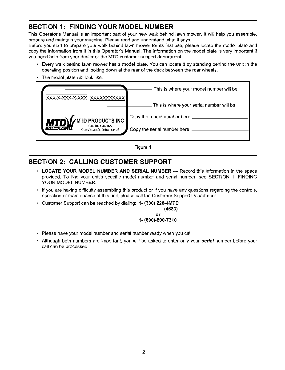
• Every walk behind lawn mower has a model plate. You can locate it by standing behind the unit in the
operating position and looking down at the rear of the deck between the rear wheels.
• The model plate will look like.
I
XXX-X-XXX-X-XXX XXXXXXXXXXX
I
_MTD PRODUCTS INC
P.o.Box3B8022
•..... CLEVELAND, OHIO 44136
Copy the model number here:
Copy the serial number here:
Figure 1
This is where your model number will be.
This is where your serial number will be.
SECTION 2: CALLING CUSTOMER SUPPORT
• LOCATE YOUR MODEL NUMBER AND SERIAL NUMBER -- Record this information in the space
provided. To find your unit's specific model number and serial number, see SECTION 1: FINDING
YOUR MODEL NUMBER.
• If you are having difficulty assembling this product or if you have any questions regarding the controls,
operation or maintenance of this unit, please call the Customer Support Department.
• Customer Support can be reached by dialing: 1- (330) 220-4MTD
(4683)
or
1- (800)-800-7310
• Please have your model number and serial number ready when you call.
• Although both numbers are important, you will be asked to enter only your serial number before your
call can be processed.
Page 3
SECTION 3: IMPORTANT SAFE OPERATION PRACTICES
WARNING: This symbol points out important safety instructions which, if not followed, could
endanger the personal safety and/or property of yourself and others, read and follow all instructions
in this manual before attempting to operate your lawn mower, failure to comply with these
instructions may result in personal injury, when you see this symbol, heed its waming.
California to cause cancer, birth defects or other reproductive harm.
WARNING: The Engine Exhaust from this product contains chemicals known to the State of
DANGER: Your lawn mower was built to be operated according to the rules for safe operation in
this manual. As with any type of power equipment, carelessness or error on the part of the operator
can result in serious injury. This lawn mower is capable of amputating hands and feet and throwing
objects. Failure to observe the following safety instructions could result in serious injuryor death.
1. GENERAL OPERATION
• Read this operator's manual carefully in its entirety
before attempting to assemble this machine. Read,
understand, and follow all instructions on the
machine and in the manual(s) before operation. Be
completely familiar with the controls and the proper
use of this machine before operating it. Keep this
manual in a safe place for future and regular
reference and for ordering replacement parts.
• Your rotary mower is a precision piece of power
equipment, not a plaything. Therefore, exercise
extreme caution at all times. Your unit has been
designed to perform one job: to mow grass. Do not
use it for any other purpose.
• Never allow children under 14 years old to operate
a power mower. Children 14 years old and over
should only operate mower under close parental
supervision. Only responsible individuals who are
familiar with these rules of safe operation should be
allowed to use your mower.
• Keep the area of operation clear of all persons,
particularly small children and pets. Stop engine
when they are in the vicinity of your mower to help
prevent blade contact or thrown object injury.
Although the area of operation should be
completely cleared of foreign objects, an object
may have been overlooked and could be
accidentally thrown by the mower in any direction
and cause serious personal injury to the operator or
any others allowed in the area.
• Wear sturdy, rough-soled work shoes and close-
fitting slacks and shirts, Shirts and pants that cover
the arms and legs and steel-toed shoes are
recommended. Do not wear loose fitting clothes or
jewelry. They can be caught in moving parts. Never
operate a unit in bare feet, sandals, slippery or light
weight (e.g. canvas) shoes.
• Always wear safety glasses or safety goggles
during operation or while performing an adjustment
or repair, to protect eyes from foreign objects that
may be thrown from the machine in any direction.
• Thoroughly inspect the area where the equipment
is to be used. Remove all stones, sticks, wire,
bones, toys and other foreign objects which could
be picked up and thrown by the mower in any
direction and cause serious personal injury to the
operator or any others allowed in the area. Plan
your mowing pattern to avoid discharge of material
toward roads, sidewalks, bystanders and the like.
To help avoid a thrown objects injury, keep
children, bystanders and helpers at least 75 feet
from the mower while it is in operation.
• Do not put hands or feet near or under rotating
parts. Keep clear of discharge opening at all times
as the rotating blade can cause injury.
• Many injuries occur as a result of the mower being
pulled over the foot during a fall. Do not hang on to
the mower if you are falling; release the handle
immediately.
• Never pull the mower toward you while you are
walking. If you must back the mower away from a
wall or obstruction first look down and behind, and
then follow these steps:
• Step back from the mower to fully extend your
arms.
• Be sure you are well balanced with sure
footing.
• Pull the mower back slowly, no more than half
way toward you.
• Repeat these steps as needed.
• Do not operate the mower while under the
influence of alcohol or drugs.
Page 4
• Donotengagetheself-propelledmechanismon
unitssoequippedwhilestartingengine.
• Thebladecontrolhandleisasafetydevice.Never
attempttobypassitsoperation.Doingsomakes
thesafetydeviceinoperativeandmayresultin
personalinjurythroughcontactwiththerotating
blade.The bladecontrolhandlemustoperate
easilyinbothdirectionsandautomaticallyreturnto
thedisengagedpositionwhenreleased.
• Neveroperatethemowerinwetgrass.Alwaysbe
sureof yourfooting.A slipandfallcancause
seriouspersonalinjury.Keepafirmholdonthe
handleandwalk,neverrun.Ifyoufeelyouare
losingyour footing,RELEASETHE BLADE
CONTROLHANDLEIMMEDIATELYandtheblade
willstoprotatingwithinthreeseconds.
• Mowonlyindaylightorgoodartificiallight.
• Stopthebladewhencrossinggraveldrives,walks
orroads.
• Iftheequipmentshouldstarttovibrateabnormally,
stoptheengineandcheckimmediatelyfor the
cause.Vibrationisgenerallyawarningoftrouble.
• Shuttheengineoffandwaituntilthebladecomes
to a completestopbeforeremovingthe grass
catcheroruncloggingthechute.Thecuttingblade
continuesto rotatefor a fewsecondsafterthe
engineisshutoff.Neverplaceanypartofthebody
inthebladeareauntilyouaresurethebladehas
stoppedrotating.
• Neveroperatemowerwithoutproperguards,grass
catcher,platesorothersafetyprotectivedevicesin
place.
• Mufflerandenginebecomehotandcancausea
burn.Donottouch.
• Onlyuseaccessoriesapprovedforthismachineby
themanufacturer.Read,understand,andfollowall
instructionsprovidedwiththeapprovedaccessory.
• If situationsoccurwhicharenotcoveredin this
manual,usecareandgoodjudgment.Contactyour
dealerforassistance.Telephone1-800-800-7310
forthenameofyournearestdealer.
2. SLOPE OPERATION
For your safety, use the slope gauge included as part of
this manual to measure slopes before operating this unit
on a sloped or hilly area. If the slope is greater than 15
degrees as shown on the slope gauge, do not operate this
unit on that area or serious injury could result.
DO:
• Mow across the face of slopes; never up and down.
Exercise extreme caution when changing direction
on slopes.
• Watch for holes, ruts, hidden objects, or bumps.
Tall grass can hide obstacles.
• Always be sure of your footing. A slip and fall can
cause serious personal injury. If you feel you are
losing your balance release the blade control
handle immediately and the blade will stop in less
than 3 seconds.
DO NOT:
• Do not mow near drop-offs, ditches or
embankments. The operator could lose footing or
balance.
• Do not mow slopes greater than 15 degrees as
shown on the slope gauge.
• Do not mow on wet grass. Reduced footing could
cause slipping.
3,
CHILDREN
Tragic accidents can occur if the operator is not alert to the
presence of children. Children are often attracted to the
mower and the mowing activity. Never assume that
children will remain where you last saw them.
• Keep children out of the mowing area and under
the watchful care of a responsible adult other than
the operator.
• Be alert and turn mower off if a child enters the
area.
• Before and while moving backwards, look behind
and down for small children or other objects.
• Never allow children under age 14 to operate the
mower. Children 14 years of age and above
should read and understand the operation
instructions and safety rules in this manual.
• Use extreme care when approaching blind corners,
shrubs, trees, or other objects that may obscure
your vision of a child or hazard.
4,
SERVICE
• Use extreme care in handling gasoline and other
fuels. They are extremely flammable and the
vapors are explosive.
• Use only an approved gasoline container.
• Never remove gas cap or add fuel while the engine
is running. Allow engine to cool at least two
minutes before refueling.
• Replace gasoline cap securely and wipe off any
spilled gasoline before starting the engine as it may
cause a fire or explosion.
• Extinguish all cigarettes, cigars, pipes and other
sources of ignition.
• Never refuel machine indoors because flammable
vapors will accumulate in the area.
• Never store the machine or fuel container inside
where there is an open flame or spark such as a
gas water heater, space heater, or furnace.
• Never run an engine inside a closed area.
Page 5
• Toreducefirehazard,keepmowerfreeof grass,
leaves,orotherdebrisbuild-up.Cleanupoilorfuel
spillage.Allowmowertocoolat least5 minutes
beforestoring.
• Beforecleaning,repairing,or inspecting,make
certainthe bladeand all moving parts have
stopped. Disconnect the spark plug wire, and keep
the wire away from the spark plug to prevent
accidental starting.
• Check the blade and engine mounting bolts at
frequent intervals for proper tightness. Also,
visually inspect blade for damage (e.g., bent,
cracked or worn). Replace with blade which meets
original equipment specifications listed in this
manual.
• Keep all nuts, bolts, and screws tight to be sure the
equipment is in safe working condition.
• Never tamper with safety devices. Check their
proper operation regularly.
After striking a foreign object, stop the engine,
remove the wire from the spark plug, and
thoroughly inspect the mower for any damage.
Repair the damage before starting and operating
the mower.
• Never attempt to make a wheel or cutting height
adjustment while the engine is running.
• Grass catcher components are subject to wear,
damage and deterioration, which could expose
moving parts or allow objects to be thrown. For
safety protection, frequently check components and
replace with manufacturer's recommended parts,
when necessary.
• Mower blades are sharp and can cut. Wrap the
blade(s) or wear gloves, and use extra caution
when servicing them.
• Do not change the engine governor setting or
overspeed the engine. Excessive engine speeds
are dangerous.
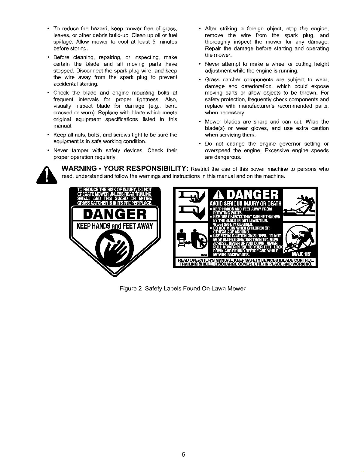
i_b WARNING - YOUR RESPONSIBILITY: Restrict the use of this power machine to persons who
read, understand and follow the warnings and instructions in this manual and on the machine.
DANGER
READ OPERATOR'S MANUAL KEEP SAFETY DEVICES (BLADE CONTROL,
Figure 2 Safety Labels Found On Lawn Mower
,IN PLACE AND WORKING.
Page 6
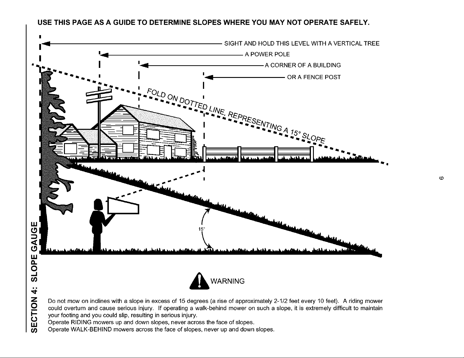
USE THIS PAGE AS A GUIDE TO DETERMINE SLOPES WHERE YOU MAY NOT OPERATE SAFELY.
i'<l
SIGHT AND HOLD THIS LEVEL WITH A VERTICAL TREE
A POWER POLE
I
19 A CORNER OF A BUILDING
I ' .ii OR A FENCE POST
I
"'"
,4 1_o
¢0
15°
_J
WARNING
Do not mow on inclines with a slope in excess of 15 degrees (a rise of approximately 2-1/2 feet every 10 feet), A riding mower
could overturn and cause serious injury. If operating a walk-behind mower on such a slope, it is extremely difficult to maintain
your footing and you could slip, resulting in serious injury.
b
Operate RIDING mowers up and down slopes, never across the face of slopes,
Operate WALK-BEHIND mowers across the face of slopes, never up and down slopes.
Page 7
SECTION 5: UNPACKING
REMOVING UNIT FROM CARTON
Remove staples, break glue on top flaps, or cut tape at carton end and peel along top flap to open carton.
Remove loose parts if included with unit (i.e., operator's manual, etc.).
Make sure the cables are straight and not crimped while removing loose parts or the unit from the carton.
Cut along dotted lines and lay carton down flat.
Remove packing material.
Roll or slide unit out of carton. Check carton thoroughly for loose parts.
TOOLS REQUIRED
Pair of Pliers (Not necessary, but helpful).
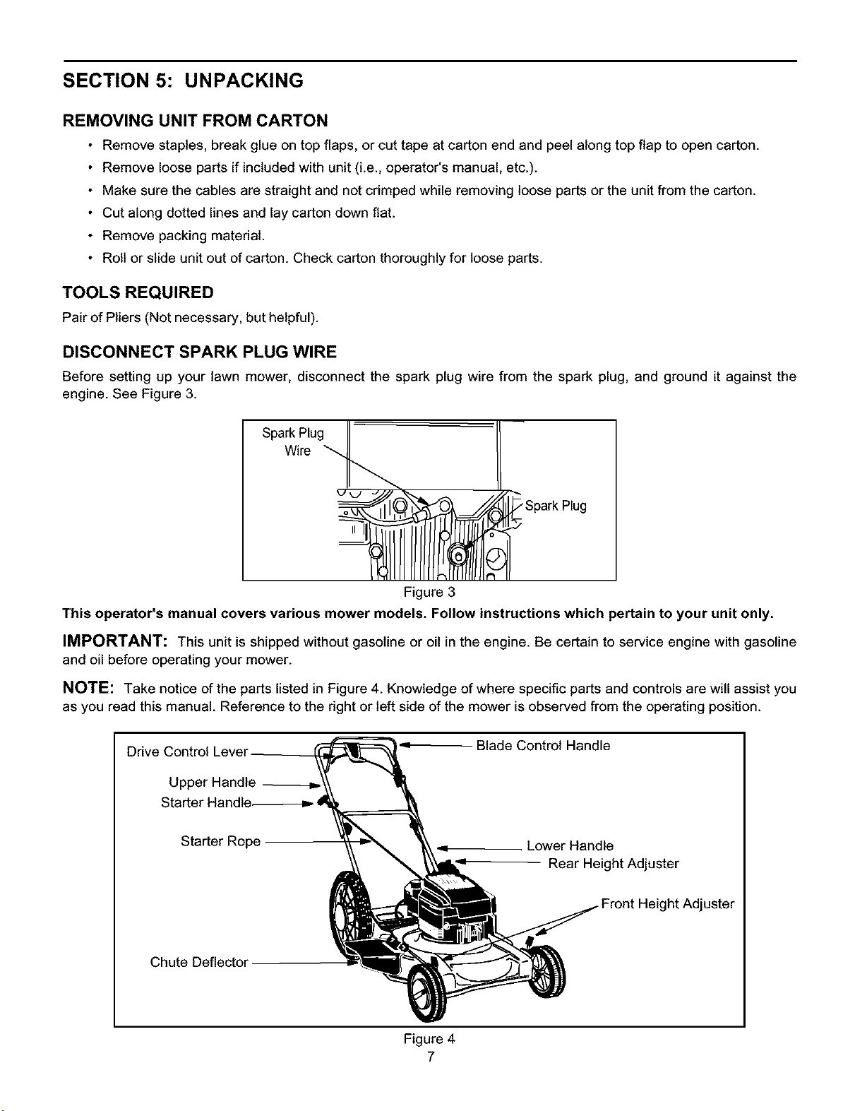
DISCONNECT SPARK PLUG WIRE
Before setting up your lawn mower, disconnect the spark plug wire from the spark plug, and ground it against the
engine. See Figure 3.
Spark Plug
Wire
Figure 3
This operator's manual covers various mower models. Follow instructions which pertain to your unit only.
IMPORTANT: This unit is shipped without gasoline or oil in the engine. Be certain to service engine with gasoline
and oil before operating your mower.
NOTE: Take notice of the parts listed in Figure 4. Knowledge of where specific parts and controls are will assist you
as you read this manual. Reference to the right or left side of the mower is observed from the operating position.
Drive Centre
Upper Handle --=
Starter
Starter Rope
Chute Deflector
Blade Control Handle
Lower Handle
Rear Height Adjuster
Height Adjuster
Figure 4
7
Page 8
Starter
Rope
Height Bracket
Handle Mounting
Adjuster
Lever
Guide
Hairpin Clip Weld
Carria_
HandKnob
A
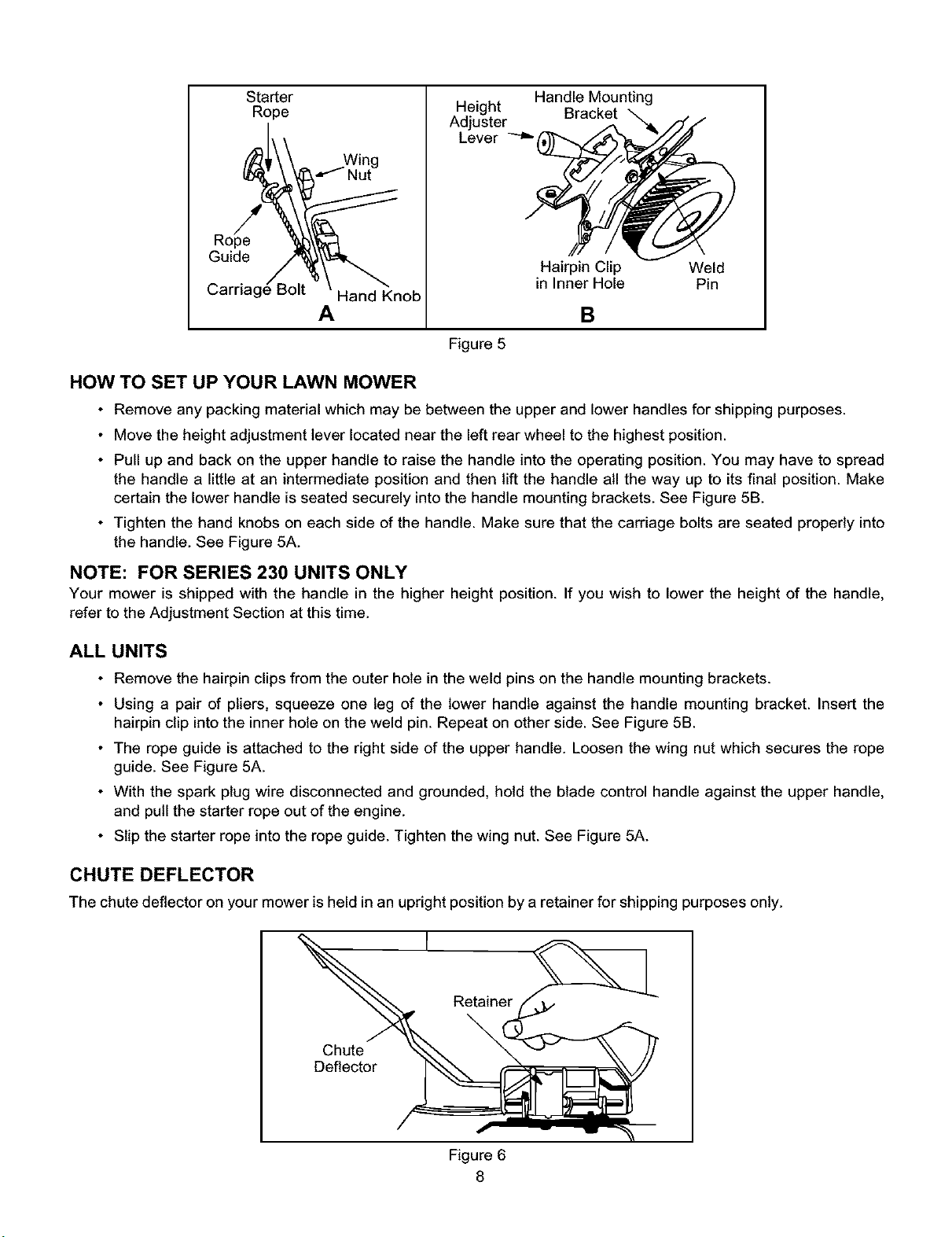
Figure 5
HOW TO SET UP YOUR LAWN MOWER
• Remove any packing material which may be between the upper and lower handles for shipping purposes.
• Move the height adjustment lever located near the left rear wheel to the highest position.
• Pull up and back on the upper handle to raise the handle into the operating position. You may have to spread
the handle a little at an intermediate position and then lift the handle all the way up to its final position. Make
certain the lower handle is seated securely into the handle mounting brackets. See Figure 5B.
• Tighten the hand knobs on each side of the handle. Make sure that the carriage bolts are seated properly into
the handle. See Figure 5A.
NOTE: FOR SERIES 230 UNITS ONLY
Your mower is shipped with the handle in the higher height position. If you wish to lower the height of the handle,
refer to the Adjustment Section at this time.
ALL UNITS
• Remove the hairpin clips from the outer hole in the weld pins on the handle mounting brackets.
• Using a pair of pliers, squeeze one leg of the lower handle against the handle mounting bracket. Insert the
hairpin clip into the inner hole on the weld pin. Repeat on other side. See Figure 5B.
• The rope guide is attached to the right side of the upper handle. Loosen the wing nut which secures the rope
guide. See Figure 5A.
• With the spark plug wire disconnected and grounded, hold the blade control handle against the upper handle,
and pull the starter rope out of the engine.
• Slip the starter rope into the rope guide. Tighten the wing nut. See Figure 5A.
in Inner Hole Pin
B
CHUTE DEFLECTOR
The chute deflector on your mower is held in an upright positionby a retainer for shipping purposes only.
Retainer
\
Chute
Deflector
Figure 6
8
Page 9
• To remove this retainer, move the spring-loaded chute toward the engine by pushing above the retainer.
• Remove the retainer and carefully lower the chute into operating position, keeping fingers out of the way. See
Figure 6.
_, WARNING: The shipping chute retainer must be removed and discarded before operating the mower.
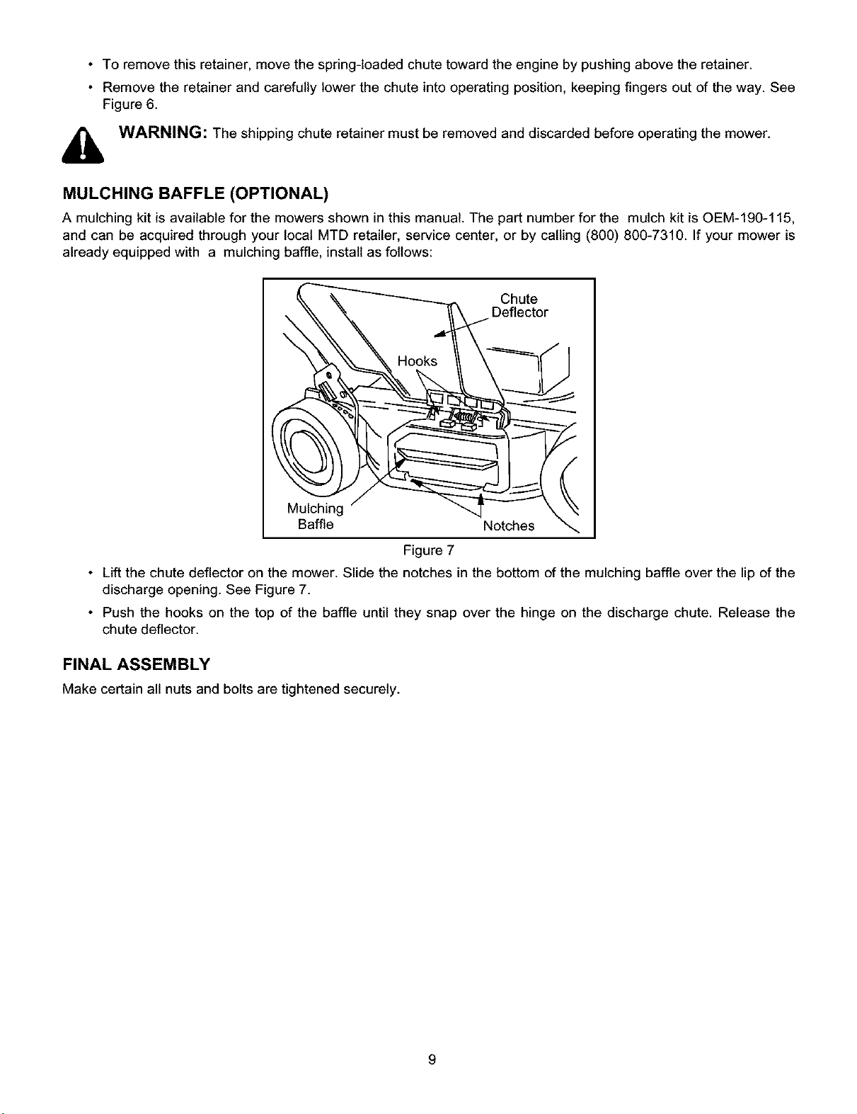
MULCHING BAFFLE (OPTIONAL)
A mulching kit is available for the mowers shown in this manual. The part number for the mulch kit is OEM-190-115,
and can be acquired through your local MTD retailer, service center, or by calling (800) 800-7310. If your mower is
already equipped with a mulching baffle, install as follows:
DCheUtc_'or
Mulching ""4
Baffle Notches
Figure 7
• Lift the chute deflector on the mower. Slide the notches in the bottom of the mulching baffle over the lip of the
discharge opening. See Figure 7.
• Push the hooks on the top of the baffle until they snap over the hinge on the discharge chute. Release the
chute deflector.
FINAL ASSEMBLY
Make certain all nuts and bolts are tightened securely.
Page 10

SECTION 6: CONTROLS
Control _ \
Drive Clutcl_
Rec
Sta'_t Handle
A
Figure 8
Blade Control Handle
Recoil Starter
B
BLADECONTROLHANDLE
_hb WARNING: This control mechanism is a safety device. Never attempt to bypass its operations.
The blade control handle is located on the upper handle of the mower. See Figure 8. The blade control handle must
be depressed in order to operate the unit. Release the blade control handle to stop the engine and blade.
WARNING: The blade will be rotating whenever the engine is running.
OPTIONAL THROTTLE CONTROLS
Your unit will be equipped with one of three optional throttle controls. Follow the instructions which pertain to your unit.
• The throttle control is located on the left side of the upper handle. It is used to regulate engine speed.
• The throttle control is located on the engine. It is used to regulate engine speed.
• The engine is equipped with a constant speed throttle which is set at full throttle for maximum engine and
cutting performance.
the engine, do not adjust the throttle control with the engine running.
WARNING: The throttle control can not be used to stop the engine. If your throttle control is located on
RECOIL STARTER
The recoil starter handle is attached to the handle. See Figure 8. Stand behind the unit in the operating position to
start the unit.
DRIVECLUTCHCONTROL
Squeeze the drive clutch control against the upper handle to engage drive. Release the drive clutch control to slow
down when negotiating an obstacle, making a turn or stopping. There are two different styles of drive clutch controls
that are available. See Figure 8.
10
Page 11

SECTION 7: OPERATION
WARNING: Keep hands and feet away from the chute area on cutting deck. See Figure 2 in the Safety
Section.
WARNING: The operation of any lawn mower can result in foreign objects being thrown into the eyes,
,_ which can result in severe eye damage. Always wear safety glasses or eye shields. We recommend wide
vision safety mask for over spectacles or standard safety glasses.
NOTE: For shipping purposes your mower is set with the wheels in a low cutting height position. For best results
raise the cutting position until it is determined which height is best for your lawn. See cutting height adjustment
section.
GAS AND OIL FILL-UP
Service the engine with gasoline and oil as instructed in the separate engine manual packed with your mower. Read
instructions carefully.
WARNING: Never fill fuel tank indoors, with engine running or until the engine has been allowed to coolfor at least two minutes after running.
BEFORE STARTING
• Attach spark plug wire to spark plug. Make certain the metal cap on the end of the spark plug wire (inside the
rubber boot) is fastened securely over the metal tip on the spark plug.
• Before each use, check for proper drive clutch operation by performing the following procedure before starting
the engine.
With the drive clutch control released, push mower forward. It should move freely. Pull mower backward. It should
move with only a small amount of resistance.
If the rear wheels tend to lock up, the clutch may not be releasing completely. Do not start the engine until
corrections have been made.
Check the control cable for severe bend, kinks or binding, or grass build-up around the belt. Correct and adjust as
required.
Refer to instructions under "Drive Clutch Control Adjustment" in the Adjustment Section for loosening the drive belt.
TO START ENGINE AND ENGAGE BLADE
WARNING: When starting the unit for the first time, face the mower against a solid object such as a wall,
,_ fence, etc. Start the unit, and if it shows any signs of motion with the drive clutch control disengaged, shut
the engine off immediately.
• Move the throttle control lever (if equipped) to the full throttle position (rabbit).
• If engine is equipped with a primer, prime engine as instructed in the separate engine manual packed with your
unit. Normally, the primer requires three full pumps when the temperature is over 55°F and five pushes to the
primer when it is colder.
• Standing behind the unit, depress the blade control handle and hold it against the upper handle.
• Grasp starter handle and pull the rope out slowly until the engine reaches the start of compression cycle (rope
will pull slightly harder at this point). Let the rope rewind slowly. See Figure 8.
• Pull rope with a rapid, continuous, full arm stroke. Keep a firm grip on starter handle. Return it slowly to the
rope guide. See Figure 8.
11
Page 12

TO STOP ENGINE AND BLADE
• Move throttle control lever (if equipped on the handle) to the SLOW position (turtle).
• Release the blade control handle to stop the engine and blade.
WARNING: The blade continues to rotate for a few seconds after the engine is shut off.
• Disconnect the spark plug wire and ground it against the engine to prevent accidental starting while equipment
is unattended.
USING YOUR ROTARY MOWER
Be sure that lawn is clear of stones, sticks, wire, or other objects which could damage the lawn mower or engine.
Such objects could be accidently thrown by the mower in any direction and cause serious personal injury to the
operator and others.
For best results, do not cut wet grass because it tends to stick to the underside of the mower, preventing proper
discharge of grass clippings, and could cause you to slip and fall. New grass, thick grass or wet grass may require a
narrower cut. Ground speed should be adjusted to the condition of the lawn.
The best mowing pattern is one that allows the clippings to discharge towards the uncut part of the lawn. This permits
recutting of the clippings to further pulverize them. When cutting high weeds, discharge towards the cut portion, then
recut at right angles to first direction.
For a healthy lawn, always cut off one-third or less of the total length of the grass. Lawn should be cut in the fall as
long as there is growth.
This mower is designed to be operated at full throttle to give you the best cut and do the most effective job of bagging
the cut grass.
WARNING: If you strike a foreign object, stop the engine. Remove wire from spark plug, thoroughly
inspect the mower for any damage, and repair the damage before restarting and operating the mower.
Extensive vibration of the mower during operation is an indication of damage. The unit should be promptly
inspected and repaired. See Safety labels in Figure 2.
SECTION 8: ADJUSTMENTS
_, WARNING: Do not at any time make any adjustment to lawn mower without first stopping engine and
CUTTING HEIGHT ADJUSTMENT
disconnecting spark plug wire.
Front Height Adjustment Lever
Rear Height Adjustment Lever
Figure 9
12
Page 13

Anadjustingplateandthumbleverateachfrontwheelprovidescuttingheightadjustment.Asingleleverneartheleft
rearwheeladjustsbothrearwheelssimultaneously.Eachadjustingplatehasnineheightpositions.Heightofcutwill
bechangedwhenthethumbleveris movedfromonepositiontoanother.Simplydepressthelevertowardswheel
andmovewheelandleverassemblytodesiredposition.SeeFigure9.
HANDLE HEIGHT ADJUSTMENT
(230 series mowers only)
Your mower is shipped with the handle in the higher height position. To lower the handle height, proceed as follows.
• Remove the starter rope from the rope guide.
• Remove the upper handle by removing the hand knobs and carriage bolts. Lay the upper handle out of the
way, being careful not to bend or kink the cables.
• Remove the hairpin clips from the weld pins on the handle brackets. Press outward on the legs of the lower
handle, and remove it from the mower.
Notch
Figure 10
• Turn the lower handle around so the notches on the bottom of the lower handle are facing forward as shown in
Figure 10.
• Reassemble, placing the bottom holes in the handle over the weld pins in the handle mounting bracket.
• Reassemble the upper handle.
• Place the hairpin clips in the inner holes in the weld pins and attach the starter rope as instructed in the Set-Up
Instructions.
DRIVE CLUTCH CONTROL ADJUSTMENT
Adjust the drive clutch control if:
• The mower self-propels with the drive clutch control disengaged.
• The mower does not self-propel with the drive clutch control engaged.
• The drive belt is slipping (unit hesitates while engine maintains the same speed).
A. Style 1 Controls:
• Use the adjustment wheel located in the clutch control housing to tighten or loosen the drive belt. See Figure
11A.
• You can use the adjustment wheel to also determine the position in which the drive clutch control is engaged. If
it is more comfortable to have the drive engaged with the lever further away from the handle, tighten the drive
belt.
13
Page 14

B. Style 2 Controls:
To adjust the tension on the belt, first adjust the cable at the cable bracket on the handle. Proceed as follows:
• Engage the drive clutch control handle (squeeze handle against the upper handle). Measure the spring on the
drive clutch cable. It should measure approximately 2-1/4 inches long as shown in Figure 11B, inset.
• If adjustment is necessary, loosen the screw which secures the cable bracket to the upper handle. The cable
bracket is slotted, slide it up or down the handle as necessary to achieve the 2-1/4 inch measurement.
• If the measurement can not be achieved in the previous step, unhook the Z end of the spring from lower hole
and insert into the higher adjustment hole.
• Check the spring length as instructed in step one.
[]
Loosen
(Style 1) (Style 2)
Tighten
Adjustment
Wheel
Figure 11
Adjustment
Hole
Cable-
Bracket
Z End of Cable
In Lower Hole
CARBURETOR ADJUSTMENTS
_1= WARNING: If any adjustments are made to the engine while the engine is running (e.g. carburetor),
To adjust carburetor, refer to the separate engine manual packed with your mower.
keep clear of all moving parts. Be careful of heated surfaces and muffler.
NOTE: A dirty air cleaner will cause an engine to run rough. Be certain air cleaner is clean and attached to the
carburetor before adjusting carburetor.
SECTION 9: MAINTENANCE
Lube
Lube _ Lube
Figure 12
14
Page 15

LUBRICATION
_ ARNING: Always stop engine and disconnect spark plug wire before cleaning, lubricatingor doing any
kind of work on lawn mower.
Blade Control
Lubricate the pivot points on the blade control handle and the brake cable at least once a season with light oil. See
Figure 12. The blade control must operate freely in both directions.
Chute Deflector
Lubricate the torsion spring and pivot point periodically with light eil to prevent any rust or binding. Deflector must
work freely.
Wheels
If your lawn mower has ball bearing wheels, lubricate at least once a season with light oil (or engine oil). Also, if the
wheels are removed for any reason, lubricate the surface of the axle bolt and the inner surface of the wheel.
Engine
Follow engine manual for lubrication instructions.
Transmission
The transmission is pre-lubricated and sealed at the factory. It does not require checking. If disassembled for any
reason, fillwith 2 ounces of Alvania grease, part number 737-0168.
_ ARNING: Be sure to disconnect and ground the spark plug wire before performing any repairs or
CUTTING BLADE
_ ARNING: Periodically inspect the blade adapter for cracks, especially if you strike a foreign object.
When removing the cutting blade for sharpening or replacement, protect hands by using heavy gloves or a rag to
grasp the cutting blade.
maintenance.
Replace when necessary.
Sharpening Blade:
Follow the original angle of grind as a guide. Make sure that each cutting edge receives an equal amount of grinding
to prevent an unbalanced blade.
NOTE: An unbalanced blade will cause excessive vibration when rotating at high speeds, may cause damage to
the mower and could break, causing personal injury.
Test the blade by balancing it on a round shaft screwdriver or a blade balancer. If the blade is not balanced, remove
metal from the heavy side until it balances evenly. We recommend that the blade be always removed from the
adapter for the best test of balance.
Before reassembling the blade and the blade adapter to the unit, lubricate the engine crankshaft and the inner
surface of the blade adapter with light oil (or engine oil). Also lubricate the crankshaft bolt.
15
Page 16

Replacing Blade
NOTE: If the adapter is keyed, make sure that the key in the adapter is aligned with the key sloton the crankshaft.
• Place the two pulleys, the flat washer, the spring washer and the spacer on the engine crankshaft. See Figure
13.
_L'_ Spacer
Spdng
Flat
Washer ---_
Blade Adapter
Figure 13
• Install the blade adapter on the crankshaft with the "star" away from the engine. See Figure 14.
Blade Adapter
Washer
Blade Bell
Support
Hex Bolt
Figure 14
• Place the blade with the side marked bottom (or with part number) facing away from the adapter.
• Place the blade bell support over the blade, aligning the tabs in the holes of the blade with the hole in the bell
support and insert the hex bolt through the blade assembly. Refer to Figure 14 for the correct order of
assembly.
• Tighten the hex bolt according to the blade mounting torque mentioned below.
BLADE MOUNTING TORQUE
Center Bolt: 450 in. tbs. min., 600 in. Ibs. max.;
To ensure safe operation of your unit, all nuts and bolts must be checked periodically for correct tightness.
DECK
The underside of the mower deck should be cleaned after each use to prevent a buildup of grass clippings, leaves,
dirt or other matter. If this debris is allowed to accumulate, it will invite rust and corrosion, and may cause an uneven
discharge of grass clippings.
The deck may be cleaned by tilting the mower and scraping clean with a suitable tool (make certain the spark plug
wire is disconnected, the fuel tank is empty or sealed, and the air filter and carburetor are away from the ground).
16
Page 17

ENGINE
Refer to the separate engine manual for engine maintenance instructions.
• Maintain engine oil as instructed in the separate engine manual packed with your unit. Read and fellow
instructionscarefully.
• Service air cleaner every 25 hours under normal conditions. Clean every few hours under extremely dusty
conditions. Poor engine performance and flooding usually indicates that the air cleaner should be serviced. To
service the air cleaner, refer to the separate engine manual packed with your unit.
• The spark plug should be cleaned and the gap reset once a season. Spark plug replacement is recommended
at the start of each mowing season; check engine manual for correct plug type and gap specifications.
• Clean the engine regularly with a cloth or brush. Keep the cooling system (blower housing area) clean to
permit proper air circulation which is essential to engine performance and life. Be certain to remove all grass,
dirtand combustible debris from muffler area.
BELT REPLACEMENT
Disconnect the spark plug wire and ground it against the engine.
• Drain the fuel tank or place a piece of plastic beneath the cap to prevent gasoline leakage.
• Remove the transmission belt cover by removing the three bolts. See Figure 15.
• Tip the mower back on its sidewith the air filter side away from the ground. Block securely.
Hex Bolts
Hex Bolts
Transmission
Belt Cover
Self-Tappin!
Screws
Figure 15
• Remove the center bolt which secures the blade to the crankshaft. See Figure 14.
• Remove the blade bell support, the blade, and the blade adapter, and the pulley half. See Figure 13. Remove
the belt.
• Using a 3/8" wrench, remove the two self-tapping screws which hold the inside belt cover, and remove the
cover. See Figure 15.
• Remove the belt from between the idler pulley and the belt guard on the idler pulley bracket.
• Remove the belt from the transmission pulley.
• Push the idler pulley up and out of the way. See Figure 16.
• Slide the belt in from the rear of the deck, and place it around the transmission pulley.
_mission
17
Page 18

Idler Pulley
Belt
J
Figure 16
• Release the idler pulley so that it falls down into position. Slide the belt in between the idler pulley and the belt
cover on the idler pulley bracket. See Figure 17.
• Lightly grease the crankshaft. Place the belt between the two pulley halves, and reassemble the blade adapter
and the blade.
Belt Guard
Pulley
Figure 17
• Reassemble the transmission belt cover. Make sure to maintain the correct order while reassembling the
blade, the blade adapter, and the pulleys, the washers, and the spacer. Refer to Figure 13.
Idler Pulley
NOTE: When reassembling the transmission belt cover, make sure that the belt cover is approximately 1/8" away
from the belt. Also make sure to tighten all nuts and bolts securely. If you had put plastic under the gas cap before
tipping the unit, remove it now.
SECTION 10: OFF-SEASON STORAGE
The following steps should be taken to prepare lawn mower for storage.
• Clean and lubricate the mower thoroughly as described in the lubrication instructions.
• Refer to separate engine manual for correct engine storage instructions.
• Coat mower's cutting blade and underside of cutting deck with light oil to prevent rusting.
• Store mower in a dry, clean area. Do not store next to corrosive materials, such as fertilizer.
NOTE: When stodngany type of power equipmentin a poorlyventilatedor metal storageshed,rust-proofthe equipment.
Lightly coat the equipment with a light oil or silicone, especially cables and all moving parts.
18
Page 19

SECTION 11: TROUBLE SHOOTING GUIDE
Possible Cause(s)
Engine fails to
start
Engine runs
erratic
Engine
overheats
Occasional skip Spark plug gap too close.
(hesitates) at Carburetor idle mixture adjustment
high speed improperly set,
Idles poorly Spark plug fouled, faulty or gap too Reset gap to .030" or replace spark plug.
Excessive Cutting blade loose or unbalanced. Tighten blade and adapter. Balance blade.
vibration Bent cutting blade. See an authorized service dealer.
Mower will not Engine speed too low. Set throttle between 3/4 and full throttle.
mulch grass Wet grass. Do not mow when grass is wet; wait until later to cut.
Uneven cut Wheels not positioned correctly. Place all four wheels in same height position.
Wheels will not Belt not installed properly. Check belt for proper pulley installation and movement.
propel** Debris clogging drive operation. Clean out debris.
Blade control handle disengaged,
Spark plug wire disconnected.
Dirty aircleaner.
Primer button not depressed.
Throttle control lever not in correct
starting position(if so equipped).
Fuel tank empty or stale fuel.
Blocked fuel line (if so equipped),
Faulty spark plug,
Engine flooded.
Unit running in START position.
Spark plug wire loose.
Blocked fuel line (if so equipped) or
stale fuel.
Vent in gas cap plugged,
Water or dirt in fuel system.
Dirty air cleaner.
Carburetor out of adjustment.
Engine oil level low,
Dirty air cleaner.
Air flow restricted.
Carburetor not adjusted properly.
wide.
Carburetor improperly adjusted. Refer to the engine manual packed with your unit.
Dirty air cleaner. Refer to the engine manual packed with your unit.
Excessively high grass. Mow once at a high cutting height, then mow again at
Dull blade. Sharpen or replace blade.
Corrective ActionsTrouble
Engage blade control handle.
Connect wire to spark plug.
Refer to the engine manual packed with your unit.
Refer to the engine manual packed with your unit.
Move throttle lever to FAST or START position.
Fill tank with clean fresh gasoline. Fuel will not last over thirty
days unless afuel stabilizer is used.
Clean fuel line.
Clean, adjust gap or replace.
Refer to the engine manual packed with your unit,
Move throttle lever to FAST position,
Connect and tighten spark plug wire. Check spark plug for
fouling.
Clean fuel line; fill tank with clean, fresh gasoline. Fuel will
not last over thirty days unless a fuel stabilizer is added,
Clear vent or threads or replace.
Drain fuel tank. Refill with fresh fuel.
Refer to the engine manual packed with your unit.
Refer to the engine manual packed with your unit.
Fill crankcase with proper oil.
Refer to the engine manual packed with your unit.
Stop engine and disconnect spark plug wire. Remove blower
housing and clean,
Refer to the engine manual packed with your unit or see an
authorized service dealer,*
Adjust gap to ,030".
Refer to the engine manual packed with your unit.
desired height or make a narrower cutting swath (1/2 width).
**Self-propelled models only
Note: For repairs beyond the minor adjustments above, contact your local authorized service dealer.
19
Page 20

Model Series 230
63
61
68
49-
101
83_
Z
51
See engine
52
operator's manuai,
31
44
43
33
,36
1(
18.
17
30
29
28
27
13
88
03
15-
2
20
Page 21

Model Series 230
REE
NO. PART NO.
1 710-1044
2 736-0524A
3 742-0642
742-0742
4 748-0376C
753-0588 Blade Adapter Kit
5
756-0961 Lower Pulley Half
6
756-0962 Upper Pulley Half
7
736-0513 Spr. Wash..89 I.D.
8
748-0358 Crankshaft Spacer
9
736-0514 FI-Wash..885 I.D.
10
710-0497
11
756-0554
12
714-3009
13
720-0249
14
738-0102
15
736-0504
16
741-0484
17
634-0020
18
731-1483
19
736-0105
2O
738-0507B
21
14832
720-0190
22
15261A
23
15262B
24
736-0356
25
712-0798
26
682-0001A
27
710-0654A
28
710-0607
29
16137C
3O
712-0296
31
736-0300
32
750-0624
33
732-0726
34
710-0599
35
732-0593
36
741-0324
37
713-0353
38
16500A
39
741-0522
40
738-0719A
41
736-0160
42
17053A
43
710-0653
44
714-0104
45
736-0169
46
711-0805
47
720-0223
48
748-0190
49
736-0160
50
736-0270
51
710-0751
52
712-0324
Hex Bolt 3/8-24 x 1.5" Lg.
Blade Bell Support
22" Blade
Mulching Blade (Optional)
Blade Adapter w/star
Set Scr. #10-32 x .25" Lg. (234)
Keyed Pulley (234)
Sq. Key, Square, 3/16 x 1/2 (234)
Hub Cap, Euro,Grey 3-1/2" Dia.
Shld. Bolt .498" Dia. x 1.45"
Wave Wash..51" I.D. x .78"
Wheel Bearing (optional)
Wheel Assembly
Rear Flap
Bell-Wash..38" I.D. x .88"
Shld. Bolt .5" Dia. x .357
Spring Lever Ass'y. w/Knob
Knob Only
Height Adj. Plate
Pivot Bar
Bell Wash..39 I.D. x 1.38 O.D.
Hex Nut 3/8" x 16
22" Deck Ass'y.
Hex L-Wash. Hd. Scr. 3/8-16
Hex Wash. Hd. B-Tap Scr.5/16-18
L.H. Handle Wheel Brkt. Ass'y.
Hex Patch L-Nut 3/8-24 Thd.
FI-Wash..385" I.D. x .87"
Shld. Spacer .5" Dia.
Height Adj. Lever
Hex Self-Tap Scr. 1/4-20 x .5"
Torsion Spring
Hex Flange Bearing
#48 Chain .5" Pitch x 30 Links
Hex Bearing Cup
Hex Flange Bearing
Rear Shaft Ass'y. 21.94" Lg.
FI-Wash..531" I.D. x .93"
Chain Cover
Hex Tap Scr. 1/4 x .38" Lg.
Hairpin Clip
L-Wash. 3/8" I.D.
Shld. Pin 3/8-24 x 1.43" Lg.
Grip
Spacer .513" I.D. x .703"
FI-Wash..531" I.D. x .93"
Bell-Wash. 1/4" I.D.
Hex Bolt 1/4-20 x .62" Lg.(Grade 5)
Hex L-Nut 1/4-20 Thd.
DESCRIPTION
REF.
NO.
53
54
55
56
57
58
59
60
61
62
63
64
65
66
67
68
69
70
71
72
73
74
75
76
77
78
79
80
81
82
83
84
85
86
87
88
89
90
91
92
93
94
95
96
97
98
99
100
101
102
103
104
PART NO.
710-1270
746-0883
710-1667
731-1059
731-1058
746-0710A
731-1057
731-0620
720-0294
749-0539C
747-0824
746-0550
747-0854
749-0538C
646-0875
710-0605
746-0876
17032
746-0843
736-0501
710-0726
720-0279
746-0594
710-1205
710-1174
16309A
720-0276
726-0240
749-0928
731-1034
731-1035
731-1386A
712-0711
17055B
710-0260
16136C
16855
736-0270
710-0751
736-0119
736-0242
750-0736
732-0481
736-0258
717-0417B
754-0369
712-0414
748-0381
748-0188B
10622B
738-0137A
741-0484
16855
747-0710
DESCRIPTION
Machine Screw 1/4" x 20
Cable Housing w/o Throttle
Screw #10-16 x .625"
Mounting Cap
Control Cover-Lower Half
S.R Cable (Single Bail)
Control Cover-Upper Half
Control Lever
Foam Grip (2 Required)
Upper Handle (Single Bail)
Control Handle Assembly (Std.)
Control Cable 39" Lg.
S.R Bail Ass'y.
Upper Handle (Dual Bail)
Throttle Body (optional)
Oval C-Sunk Screw (optional)
Throttle Lever
Adapter Plate
Throttle Cable 55" Lg. (optional)
Spring Washer .66" I.D.
Hex Wash. AB-Tap Scr. 5/16 x .75" Lg.
Handle Knob 1/4-20 Thd.
Drive Cable-41.5" Lg. (Dual Bail)
Rope Guide
Curved Hd. Bolt 5/16-18 x 2"
Cable Bracket
Hand Knob
Cable Tie
Lower Handle
Chute Deflector Ass'y.
Chute Deflector Only
Mulching Baffle (Optional)
Hex Jam Nut 3/8-24 Thd.
Chain-Axle Ass'y.
Carriage Bolt 5/16-18 x .62" Lg.
R.H. Handle Wheel Brkt. Ass'y.
Ratchet Plate
Bell Washer .265 ID x .75
Cap Screw HH 1/4-20 x .620
L-Wash. 5/16" I.D.
Bell-Wash. 5/16" I.D.
Spacer .383" I.D. x .503"
Ext. Spring .5" O.D. x 3.8" Lg.
FI-Wash..385" I.D. x 1" O.D.
Transmission Comp
"V"-Belt
Weld L-Nut 1/4-20 Thd.
PawI-R.H.
PawI-L.H. (Not Shown)
Spring-Nylon
Shld. Scr..342" Dia. x .268"
Sleeve Brg. 1/2" I.D.
Pawl Plate
Hinge Pin
21
Page 22

Model Series 520
67
63
72
73
81_7778
8786 8L--__, ]
64
65
74
\ 75 76
54
55
6O
/
105
58
36
See engine
manual.
93
30\ 98
26
46
O_
13
4
3
\
2
22
Page 23

Model Series 520
REE
NO. PART NO.
1 720-0249
2 738-0102
3 736-0504
4 741-0484
5 634-0020
734-1821
6 736-0105
7 738-0507B
8 14832
9 15262B
10 15261A
14578
14579
11 736-0356
12 712-0798
13 682-0001A
14 748-0358
15 736-0513
16 736-0514
17 756-0962
18 756-0961
19 748-0376C
753-0588
20 742-0742
742-0642
21 736-0524A
22 710-1044
23 710-0654A
24 710-0607
25 782-9014
26 736-0242
27 712-0267
28 736-0300
29 712-0296
30 750-0624
31 710-0653
32 710-0599
33 712-0431
34 710-0870
35 732-0655
36 720-0223
37 682-3004
38 710-3013
39 682-7501
40 741-0413
41 736-0256
42 713-0425
43 748-0313
44 736-0329
45 713-0257
46 710-0260
47 736-0270
48 710-0599
49 17032
50 747-0710
51 714-0104
REF.
DESCRIPTION NO.
Hub Cap, Gray 52
Front Axle Bolt 53
Wave Washer (used w/Ref. 4 only) 54
Wheel Bearing (optional) 55
Front Wheel 8" x 1.75" 56
Front Wheel w/Bearing 734-1821 57
Bell Washer, .38" I.D. 58
Shoulder Bolt .5" 59
Spring Lever Assembly w/Knob 60
Pivot Bar 61
Height Adjust Plate 62
Height Adjust Assembly Complete R.H.
Height Adjust Assembly Complete LH.
Bell Washer .39" I.D. x 1.38"
Hex Nut 3/8-16
22" Deck Assembly
Crankshaft Spacer
Spring Washer .89"1.D.
Fiat Washer .88" I.D.
Upper Plulley Half
Lower Pulley Half
Blade Adapter w/star
Blade Adapter Kit
22" Mulching Blade (optional)
22" Standard Blade
Blade Bell Support
Hex Bolt 3/8"-24xl .5"
Hex TT-Tap Screw 3/8"-16x1"
Hex B-Tap Screw 5/16"x.5"
Deck Bracket
Bell Washer 5/16" I.D.
Hex Nut 5/16"-18
Fiat Washer .385" I.D. x .87" O.D.
Hex Lock Nut 3/8"-24
Shield Spacer .5"x.1"
Hex Tap Screw 1/4"x.38"
Hex Washer Head TT-Tap Scr. 1/4"-20
Flange Lock Nut 3/8"-16
Hex Bolt 3/8"-16x.625"
Height Adjustment Lever
Grip
Handle Bracket Assembly, L.H.
Hex Bolt 1/4"-20x.5"
Chaincase and Arm Assembly
Hex Flange Bearing .631" LD.
Flat Washer .635"1.D. x 1.0"O.D.
Sprocket and Axle Assembly
Spacer .63" I.D. x 1.25"
Lock Washer 1/4" I.D.
#48 Chain 1/2" Pitch x 52 Links
Carriage Bolt 5/16"-18 x .62"
Bell Washer 1/4" I.D.
Hex TT-Tap Screwl/4"-2Ox.5"
Adapter Plate
Hinge Pin
internal Cotter Pin 5/16" Dia.
63
64
65
66
67
68
69
70
71
72
73
74
75
76
77
78
79
8O
81
82
83
84
85
86
87
88
89
90
91
92
93
94
95
96
97
98
99
100
101
102
103
104
105
106
PART NO.
749-0734B
726-0240
720-0276
746-0843
746-0876
736-0501
712-0324
710-1270
746-0883
646-0875
647-0004
747-0824
720-0225
749-0539B
710-1205
710-1174
746-0710A
731-1057
731-0620
731-1058
731-1059
710-0841
731-1386A
736-0104
710-0376
734-1396
734-1397
734-1400
741-0485
734-1399
712-0329
748-0315
748-0312
736-0270
710-3015
14967
712-0267
712-0287
682-7500
710-0896
736-0302
750-0192
16136C
710-0654A
712-0627
736-0258
731-1172
16563A
717-0417B
16500A
754-0369
731-1034
720-0279
732-0593
710-0605
746-0550
DESCRIPTION
Lower Handle
Cable Tie
Hand Knob
Throttle Cable (optional)
Throttle Lever (optional)
Spring Washer .66" I.D. (optional)
Hex Lock Nut 1/4"-20
Screw 1/4"-20 x 1.3"
Control Cable Housing
Throttle Body (optional)
Control Handle Assembly (Deluxe)
Control Handle Assembly (Std.)
Foam Grip
Upper Handle
Rope Guide
Carriage Bolt 5/16"-18 x 2",Curved Head
Self Propell Cable 48"
Drive Lever Housing-Upper
Drive Control Lever
Drive Lever Housing-Lower
Cable Mounting Cap
Sunk Head Tap Screw #10 x .75"
Mulching Baffle (optional)
Internal Lock Washer 5/16" I.D.
Hex Bolt 5/16"-18 x 1.0" (GR.5)
Chevron Tire 16" x 2.125"
Inner Tube 16" x 2.125"
Rimstrip 16" x 7/8"
Flange Bearing .63" I.D.
Rim Assy Only 16" x 2.1"
Special Hex Nut 5/16"-18
Pawl and Spring Assy
Wheel Ratchet
Bell Washer 1/4" I.D.
Hex Bolt 1/4"-20 x .75"
Wheel Cover
Hex Nut 5/16"-18
Hex Nut 1/4"- 20
Rear Drive Support Assembly
Hex Tap Screw 1/4" x .38"
Flat Washer.632" x .943"
Spacer .635" I.D. x .88" x .790"
Handle Bracket Assembly- R.H.
Hex TT-Tap Screw 3/8"-16x1"
Hex Nut 5/16"-18
Flat Washer .38" I.D. x 1" O.D.
Rear Flap
Retaining Strip
Trans.Complete (see breakdown)
Hex Bearing Cup
V-Belt
Chute Deflector Assembly
Handle Knob 1/4"-20
Torsion Spring
Oval C-Sunk Screw (optional)
Control Cable 39"
23
Page 24

_8
.5\ 2\ ............j,,
_--20 "__17
REE
NO. PART NO.
1 710-1062
2 726-0329
3 618-0053
4 713-0400
5 736-0336
6 741-0413
7 16500A
8 736-0314
9 741-0479
11 717-1216
12 748-0208A
13 721-0212
15 756-0330A
16 736-0270
17 712-0351
18 738-0440
20 738-0826
21 656-0008
22 741-0556
24 782-7570
25 712-0138
REF.
DESCRIPTION NO. PART NO.
Hex Bolt 1/4-20 x 1,25" Lg, 26 732-0357A
L-Wash. 1/4" I.D. 27 618-0054
Upper Hsg. Half (Incl. Ref, 12) 28 741-0415
#48 Sprocket 7 Tooth x 1/2 Pitch 29 717-0616A
FhWash. 5/8"1.D. x ,030 30 741-0414
Hex Flange Brg, ,631"1,D. 31 721-0213
Hex Bearing Cup 34 710-0589
Thrust Wash..382" I.D. x .70" O,D, 35 736-0410
Thrust Bearing .375" I,D, x ,812" O.D. 36 17718
11 Tooth Helical Gear 37 721-0325
Flange Bearing 38 710-0653
Oil Seal 39 710-0599
FI-Pulley 5,06"1,D. 40 710-0896
Bell-Wash. ,265" I,D. x.75" 41 712-0287
Hex Nut 1/4-28 LH. Thd, 42 736-0270
Shld. Spacer ,375" Dia, x ,170 43 736-0329
Shld, Bolt ,375" Dia, x ,40" 44 746-0710A
Fl-ldler Plastic 1,50" Dia. (IncLRef, 22 45 747-0549
Needle Brg, ,375" x ,375" 46 782-7569
Idler Brk't, Ass'y, 47 17064
Hex Patch L-Nut 1/4-28 Thd. 717-0417B
38
DESCRIPTION
Extension Spring 1,12" Lg.
Lower Hsg, Half (IncL Ref. 12)
Flange Bearing ,56 Dia,
Shaft Ass'y
Flange Bearing ,629 Dia,
Oil Seal .625 Dia.
Scr, AB #10-16:,,750 HxlndWsh,
Hex Washer .26" x ,88"
Transmission Belt Guard
Plug 1/4 x .437"
Hex B-Tap Scr, 1/4-20:,375 Lg,
Hex AB-Tap Scr. 1/4 x .50" Lg.
Hex B-Tap Scr, 1/4 x ,62" Lg.
Hex Nut 1/4-20 Thd.
Bell-Wash..265" I.D. x .75"
L-Wash, 1/4" I,D,
S,£ Cable-48" Lg,
S,£ Belt Guard
Belt Guard
Belt Cover
Transmission Comp.
24
Page 25

Engine Shrouds
Part No, Color
751B281439 Dark Red
751B281440 Black
751B281443 Bright Red
Hardware: 710-1256
Part No, Color
731-1585B Black
Hardware: 710-1274
Part No, Color
731-1395A Red
731-1396A Black
731-1397A Gray
Hardware: 710-1256
Part No, Color
731-1586B Black
731-1612A Red
Hardware: 7510042823
Part No, Color
731-1402A Yellow
731-1694 Black
731-1695 Silver
731-1934 Charcoal
Hardware: 710-1256
Part No. Color
7510143208 Black
Hardware: 7510042823
Part No, Color
7511681311 Black
7511681911 Red
7511682011 G_y
PartNo. Color
751B281451 Gray
Hardware: 710-1256
(Screw)
25
Part No. Color
751B281476 Black
751B281777 Yellow
Hardware: 710-1237
(Screw)
Page 26

NOTES:
26
Page 27

27
Page 28

MANUFACTURER'S LIMITED WARRANTY FOR:
Y . c.,.esj[f
For TWO YEARS from the date of retail purchase
within the United States of America, its possessions
and territories, MTD PRODUCTS INC will, at its
option, repair or replace, for the original purchaser,
free of charge, any part or parts found to be
defective in material or workmanship. This warranty
covers units which have been operated and
maintained in accordance with the operating
instructions furnished with the unit, and which have
not been subject to misuse, abuse, commercial use,
neglect, accident, improper maintenance or
alteration.
Normal wear parts or components thereof are
subject to separate terms as noted below in the "No
Fault Ninety Day Consumer Warranty" clause.
All normal wear part failures wilt be covered on this
product for a period of 90 days regardless of cause.
After 90 days, but within the two year period, normal
wear parts failures will be covered ONLY IF caused
by defects in material or workmanship of OTHER
component parts. Normal wear parts are defined as
batteries*, belts, blades, blade adapters, grass bags,
rider deck wheels, seats, snow thrower skid shoes,
shave plates and tires.
How to obtain service: Warranty service is
available, with proof of purchase, through your local
authorized service dealer. To locate the dealer in
your area, please check the yellow pages or contact
the Customer Service Department of MTD
PRODUCTS INC, P. O. Box 368022, Cleveland,
Ohio 44136-9722. Phone 1 (330) 273-4683. The
return of a complete unit will not be accepted by the
factory unless prior written permission has been
extended by the Customer Support Department of
MTD PRODUCTS INC.
Transportation charges: Transportation charges
for the movement of any power equipment unit or
attachment are the responsibility of the purchaser.
Units exported out of the United States: MTD
PRODUCTS INC does not extend any warranty for
products sold or exported outside of the United
States of America, its possessions and territories,
except those sold through MTD PRODUCTS INC's
authorized channels of export distribution.
Other Warranties:
1. The engine or component parts thereof carry
separate warranties from their manufacturers.
Please refer to the applicable manufacturer's
warranty on these items.
2. *Batteries are covered by a 90-day replacement
warranty.
3. Log splitter pumps, valves and cylinders or
component parts thereof are covered by a one
year warranty.
4. All other warranties, express or implied,
including any implied warranty of merchantability
or fitness for a particular purpose, are hereby
expressly disclaimed in their entirety.
5. The provisions as set forth in this warranty
provide the sole and exclusive remedy of MTD
PRODUCTS INC's obligations arising from the
sales of its products. MTD PRODUCTS INC will
not be liable for incidental or consequential loss
or damage.
How state law relates to this warranty: This
limited warranty gives you specific legal rights, and
you may also have other rights which vary from state
to state. Certain disclaimers are not allowed in some
states and therefore they may not apply to you
under all circumstances.
NOTE: This warranty does not cover routine
maintenance items such as lubricants, filters, blade
sharpening and tune-ups, or adjustments such as
brake adjustments, clutch adjustments or deck
adjustments. Nor does this warranty cover normal
deterioration of the exterior finish due to use or
exposure.
 Loading...