

Page 1

OWNERS
MANUAL
75
20" & 22"
ROTARY
ASSEMBLY
OPERATION
MAINTENANCE
PARTS LIST
Important:
MOWERS
Model Numbers
114-073-000
114-074-000
114-083-000
114-084-000
Read Safety Rules and
Instructions Carefully
PRINTED IN U.S.A.
Thank you for purchasing an
American buiit product.
FORM NO. 770-3143
Page 2

INDEX
Safe Operation Practices
Assembly.................................................................. 4
Controls.....................................................................7
Operation...................................................................7
Adjustments...............................................................8
Lubrication.................................................................9
..........................................
Г
♦
♦
♦
♦
♦
♦
♦
♦
For one year from the date of orig nal retail purchase, MTD PRODUCTS INC will either
repair or replace, at its option, free cf charge, F.O.B. factory or authorized service firm, any
part or parts found to be defective in material or workmanship. Transportation charges for
the movement of any power equipment unit or attachment are the responsibility of the pur
chaser. Transportation charges for г ny parts submitted for replacement under this warran
ty must be paid by the purchaser unless such return is requested by MTD PRODUCTS INC.
This warranty will not apply to any part which has become inoperative due to misuse, ex
cessive use, accident, neglect, imp oper maintenance, alterations, or unless the unit has
been operated and maintained in accordance with the instructions furnished. This warran
ty does not apply to the engine, motor, battery, battery chargeror component parts thereof.
Please refer to the applicable manifacturer’s warranty on these items.
LIMITED WARRANTY
3
Maintenance .............................................................9
Off-Season Storage
Trouble Shooting Chart
Illustrated Parts...................................................16,17
Parts Information
................................................
...........................................
......................................
Back Cover
12
15
i
♦
♦
♦
♦
♦
♦
t
♦
♦
♦
♦
♦
♦
This warranty will not apply where he unit has been used commercially.
Warranty service is available through your local authorized service dealer or distributor. If
you do not know the dealer or distrit utor in your area, please write to the Customer Service
Department of MTD.
The return of a complete unit will n ct be accepted by the factory unless prior written per
mission has been extended by MT[>.
This warranty gives you specific leqai rights. You may also have other rights which vary
from state to state.
V
WARNING
t
This unit is equipped with an internal combustion engine and should not be used on or near any unim
proved forest-covered, brush-covered or grass-covered land unless the engine’s exhaust system is
equipped with a spark arrester meeting ap clicable local or state laws (if any). If a spark arrester is used, it
should be maintained in effective working order by the operator.
j
♦
♦
♦
♦
♦
♦
J
In the State of California the above is required by law (Section 4442 of the California Public Resources
Code). Other states may have similar laws. Federal laws apply on federal lands. A spark arrester muffler is
available at your nearest engine authorized service center.
Page 3

I W AR NI NG }
To reduce the potential for any injury, comply with the following safety instructions. Failure to comply
with the instructions may result in personal injury.
SAFE OPERATION PRACTICES FOR WALK-BEHIND MOWERS
TRAINING
1. Read this owner’s manual carefully in its en
tirety before attempting to assemble or
operate this machine. Be completely familiar
with the controls and the proper use of this
machine before operating it. Keep this manual
in a safe place for future and regular reference
and for ordering replacement parts.
2. Your rotary mower is a precision piece of
power equipment, not a plaything. Therefore,
exercise extreme caution at all times.
3. Never allow children to operate a power
mower. Only persons well acquainted with
these rules of safe operation should be al
lowed to use your mower.
4. Keep the area of operation clear of all per
sons, particularly small children and pets.
Stop engine when they are in the vicinity of
your mower. Although the area of operation
should be completely cleared of foreign ob
jects, an object may have been overlooked
and could be accidently thrown by the mower
in any direction and cause serious personal
injury to the operator or any others allowed in
the area.
PREPARATION
1. Thoroughly inspect the area where the equip
ment is to be used. Remove all stones, sticks,
wire, bones and other foreign objects which
could be picked up and thrown by the mower
in any direction and cause serious personal
injury to the operator or any others allowed in
the area.
2. Do not operate equipment when barefoot or
wearing open sandals. Always wear substan
tial footwear.
3. Do not wear loose fitting clothing that could
get caught on the mower.
4. Check the fuel before starting the engine.
Gasoline is an extremely flammable fuel. Do
not fill the gasoline tank indoors, while the
engine is running, or while the engine is still
hot. Wipe off any spilled gasoline before start
ing the engine as it may cause a fire or explo
sion.
5. Disengage the self-propelled mechanism or
drive clutch on units so equipped before start
ing the engine.
6. The blade control handle is a safety device.
Never attempt to bypass its operation. Doing
so makes the safety device inoperative and
may result in personal injury through contact
with the rotating blade. The blade control han
dle must operate easily in both directions.
7. Never attempt to make a wheel or cutting
height adjustment while the engine is run
ning.
8. Mow only in daylight or in good artificial light.
9. Never operate the equipment in wet grass.
Always be sure of your footing. A slip and fall
can cause serious personal injury. Keep a firm
hold on the handle and walk, never run. g
OPERATION
1. Do not change the engine governor settings
or overspeed the engine. Excessive engine
speeds are dangerous.
2. Do not put hands or feet near or under rotating
parts. Keep clear of the discharge opening at
all times as the rotating blade can cause in
jury.
3. Stop the blade when crossing gravel drives,
walks or roads.
4. After striking a foreign object, stop the
engine, remove the wire from the spark plug,
and thoroughly inspect the mower for any
damage. Repair the damage before restarting
and operating the mower.
5. If the equipment should start to vibrate abnor
mally, stop the engine and check immediately
for the cause. Vibration is generally a warning
of trouble.
6. Shut the engine off and wait until the blade
comes to a complete stop before removing
the grass catcher or unclogging the chute.
The cutting blade continues to rotate for a few
seconds after the engine is shut off. Never
place any part of the body in the blade area un
til you are sure the blade has stopped rotating.
7. Before cleaning, repairing or inspecting, make
certain the blade and all moving parts have
stopped. Disconnect the spark plug wire, and
keep the wire away from the spark plug to pre
vent accidental starting.
8. Do not run the engine indoors.
9. Mow across the face of slopes, never up-anddown. Exercise extreme caution when chang
ing direction on slopes. Do not mow ex
cessively steep slopes. Always be sure of
your footing. A slip and fall can cause serious
personal injury.
10. Always disconnect electric mowers (line
operated) before cleaning, repairing or ad
justing.
11. Never operate mower without proper guards,
plates or other safety protective devices in
place.
MAINTENANCE AND STORAGE
1. Check the blade and engine mounting bolts at
frequent intervals for proper tightness.
2. Keep all nuts, bolts, and screws tight to be
sure the equipment is in safe working condi
tion.
3. Never store the equipment with gasoline in
the tank inside of a building where fumes may
reach an open flame or spark. Allow the
engine to cool before storing in any en
closure.
4. To reduce fire hazard, keep the engine free of
grass, leaves, or excessive grease.
5. Check the grass catcher bag frequently for
wear or deterioration. For safety protection,
replace only with new bag meeting original
equipment specifications.
Page 4
SAFE OPERATION PRACTICES (Continued)
BLADE BRAKEICLUTCH MAINTENANCE
NOTE: Any required repair work on the biade
brake/clutch should be performed by an author- 3.
ized service dealer. If you cannot locate an author
ized service dealer, contact the manufact jrer as
set forth on your copy of the Owner’s Registration
Card.
1. The blade brake/clutch hand control is a safe
ty device. Never attempt to bypass its opera
Doing so makes the safety device in
tion.
operative and may result in personal injury
through contact with the rotating blade. This 4.
hand control must operate freely in both direc
tions.
2. Striking a solid object can cause daniage to
the blade brake/clutch or to the engine crank
shaft. Extensive vibration of the mowei during
operation is an indication of damage and the
unit should be promptly inspected and
repaired.
A leak in the lower engine crankshaft oil seal
could expose the blade brake/clutch friction
pads to excess oil resulting in blade or brake
slippage, which could increase the stopping
time of the blade. Oil collection on the floor
beneath the mower during storage may be an
indication of an oil seal leak. The unit should
be checked by an authorized service dealer.
Periodically inspect the inner control cable in
the area where it attaches to the hand control.
If the cable becomes frayed, it could cause
the blade brake/clutch to operate improperly.
Also, be careful to avoid pinching the blade
brake/clutch control cable when storing the
handle.
NOTE
This unit is'shipped WITHOUT GAS
OLINE or OIL. After assembly, see
separate engine manual for proper
fuel and engine oil recommenda
tions.
ww
-B
FIGURE 1.
Lower Handle-
у
4
Hairpin i
Cotter (A)
in Inner
Hole
,_F
Handle
Bracket
ASSEMBLY
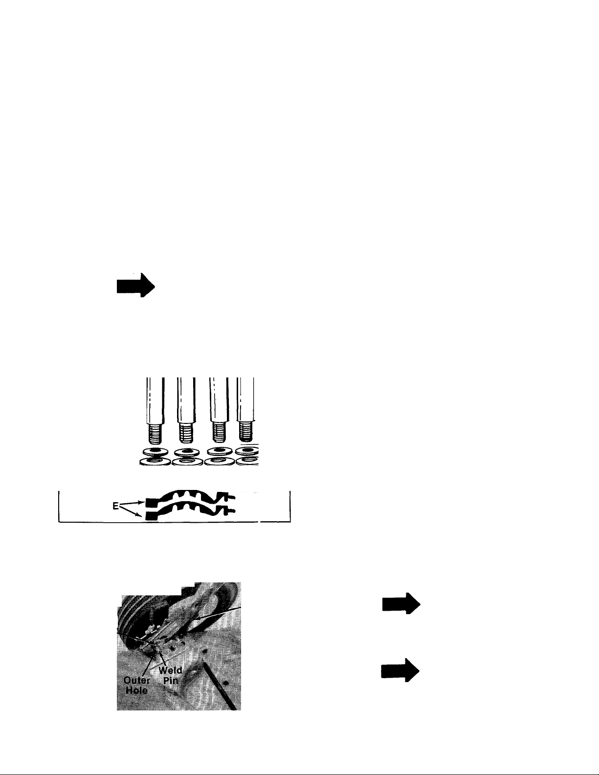
Contents of hardware pack: (See figure 1)
A (2) Hairpin Cotters
В (2) Curved Carriage Bolts 1.38" Long
C (2) Lock Washers 5/16" I.D.
D (2) Hex Nuts 5/16-18 Thread
E (2) Cable Ties
F (4) Shoulder Bolts*
— G (4) Belleville Washers 3/8" I.D. x 7/8" O.D.*
H (4) Belleville Washers 3/8" I.D. x 1-1/8" O.D.*
I (4) Hex Nuts 3/8-16 Thread*
*Units with wheeis not assembied.
1. Remove the iawn mower, ioose parts, hard
ware pack and iiterature from the carton.
Make certain all parts and literature have been
removed before the carton is discarded.
2. Extend the throttle control cable (attached to
the upper handle) and the blade brake/clutch
cable (attached to the blade brake/clutch
beneath the deck) and place on the floor. Be
careful not to bend or kink control cables.
3. Place lower handle in position over weld pins
in handle mount brackets on deck. Make cer
tain the instruction label on the lower handle
can be read from the operating position.
Secure by placing two hairpin cotters (A) in in-
------
ner hole on weld pins. See figure 2.
NOTE
It may be "necessary to bend the
ends of the lower handle outward
slightly to obtain a snug fit against
the bracket.
NOTE
FIGURE 2.
There are two (2) holes in the handle
mount brackets. Place hairpin cot
ter in the inner hole for operation.
The outer hole is for storage.
Page 5
Curved
Carri
Bolt
FIGURE 3.
Lock Washer (C)
X Nut <D)
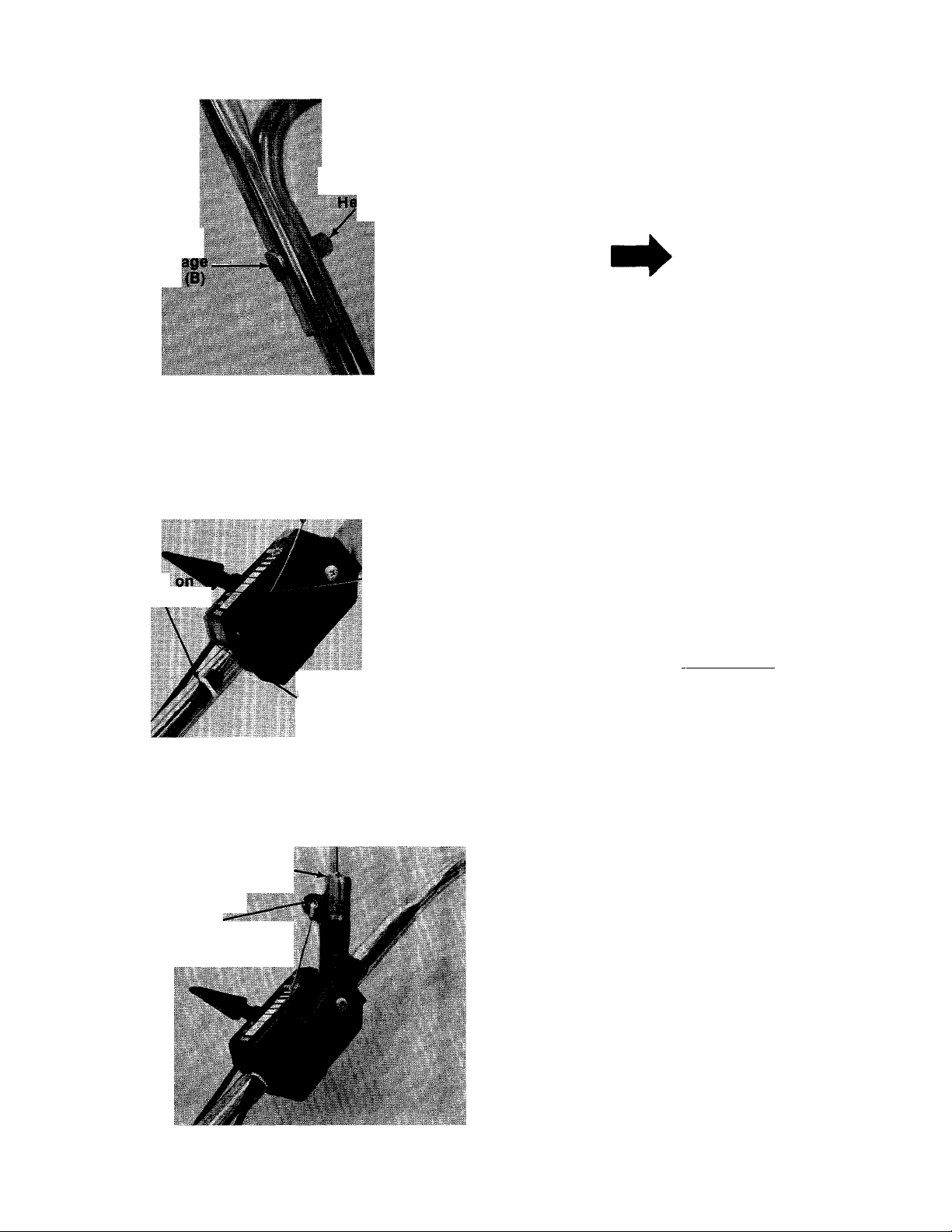
4. Place upper handle in position over lower han
dle. Control housing should be on the right
side of the handie. Secure upper handle with
two curved carriage bolts (B), lock washers (C)
■and hex nuts (D). See figure 3.
NOTE
Reference to ieft or right side of
machine is determined from oper
ator’s position at the handle facing
forward.
"Z" End of Blade
Brake/Clutch Cable.
Flange
Plastic Fitting
FIGURE 4.
Blade Control
Handle
“Z” End of
Blade Brake/Clutch
Cable
Upper Hole
on Bottom
of Housing
/
.Slot
5. Route the blade brake/clutch cable under the
lower handle. Place end of cable into the up
per hole on the bottom of the control housing,
and through the slot on the side of the hous
ing as shown. The angie of the flange on the
plastic fitting must be positioned downward
— as shown in figure 4. Be careful not to bend or
kink the cable.
\ WARNING \
The cable must be assembled as
shown for proper blade brake/
clutch operation.
6. Snap the plastic fitting on the end of the cable
into the control housing.
7. Hook the “Z” end of the blade brake/clutch
cable into the hoie in the blade brake/clutch
— control handle. See figure 5. If additional
slack is needed in order to hook the cable into
the handle, proceed as follows.
FIGURE 5.
Page 6
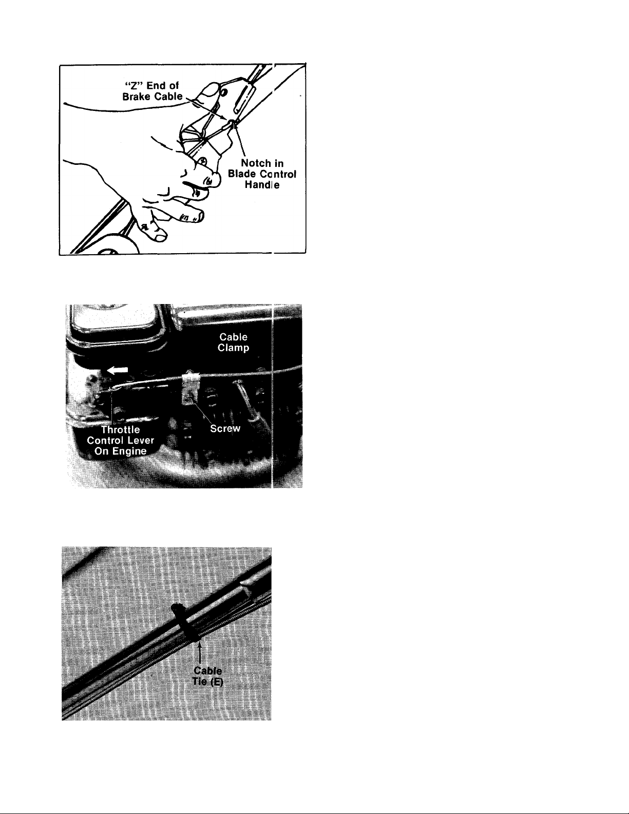
FIGURE 6.
FIGURE 7.
a. Hook the “Z” end of the cable into notch
provided in the biade controi handle. See
—figures.
b. Push release lever (see figure 12), then
squeeze blade control handle against up
per handle.
c. Release the blade control handle, unhook
the cable from the notch and hook it into
the hole in the blade control handle.
8. Remove the engine shroud if the unit is so
equipped. Replace it after attaching the throt
tle control cable.
9. Place the throttle control lever on the handle
in “Fast” position.
10.--Push the throttle control lever on the engine
to the full open position (as far toward the out
side of the unit as it will go) as shown in figure
------
7.
11. Hook the “Z” end of the throttle control cable
into the hole in the control lever on the
engine.
12. Remove the screw on the cable clamp shown
in figure 7. Slip the control casing under the
clamp. With the throttle lever on the engine
still in the full open position, replace and
tighten the screw to secure the throttle con
trol cable.
FIGURE 8.
13. Secure throttle control cable and blade
brake/clutch cable to upper and lower handles
-----
with cable ties (E) provided. See figure 8.
Page 7

Washer (
Shoulder
Bolt (F)
FIGURE 9.
Belleville
Belleville
Washer
n Use These Holes “ For Front Wheel
Hex Nut (I)
(G) s
Front Wheel
14. Units without height adjustment brackets—If the wheels on your mower are not already assembled, proceed as follows. The front wheels must be assembled in one of the three holes nearest the front of the deck. See figure
9. The rear wheels must be assembled in one
of the three holes nearest the rear of the deck.
The three holes provide three cutting heights
for your mower. Use the same hole location
for all four wheels when assembling. If wheels
are to be assembled in the lowest cutting
position (highest hole in the deck), refer to the
note below.
------
To assemble the wheels (see figure 9):
A. Place shoulder bolt (F) through wheel.
B. Place one belleville washer 7/8" O.D. (G) on
shoulder bolt, with the cupped side of
washer toward the deck (away from wheel).
C. Secure wheel to deck with one belleville
washer 1-1/8" O.D. (H) on the inside of the
deck (cupped side against the deck) and
hex nut (I).
NOTE
If the lowest cutting position (high
est hole in the deck) is used, it is
necessary to place the 1-1/8" washer
on the outside of the deck and the
7/8" washer on the inside.
15. Check all nuts and bolts for correct tightness.
A
Please note that the chute deflector
on your mower is in an upright posi
tion. It is held in that position by a
shipping block. This block is used
for shipping purposes only. It must
be removed and discarded before
your mower is put into operation.
■See figure 10.
CAUTION
Page 8

CONTROLS
THROTTLE CONTROL
The throttle is located on the right side of handle.
It controls engine speed. See figure 11.
Throttle
Control
OPERATION
Caution
Do Not Operate Mower Unless This
Guard Or Entire Grasscatcher Is In
Its Proper Place.
FIGURE 11.
BLADE BRAKE/CLUTCH CONTROL
WARNING
THIS CONTROL MECHANISM IS A
SAFETY DEVICE. NEVER ATTEMPT
TO BYPASS ITS OPERATIONS
The blade brake/clutch control is located on the
upper handle of the mower. The clutch handle
engages and disengages the blade.
To engage the blade, pull the side release lever
away from the unit. See figure 12. Pull the clutch
control handle against the upper handle. Release
side lever.
Release the clutch control handle to stop the
blade from turning.
-W -4.
.
...M_
.......
FIGURE 12.
.
Blade
Brake/Clutch
Control
Handle
FIGURE 13.
Keep hands and feet away from the chute area on
cutting deck. Seejigure 13.
NOTE
For shipping purposes your mower
is set with the wheels in a low cut
ting height position. For best re
sults raise the cutting position un
til it is determined which height is
best for your lawn. See cutting
height adjustment.
BEFORE STARTING
1. Fill sump with oil, as instructed in the
separate engine manual packed with your
unit.
2. Fill fuel tank, using clean, fresh, lead-free,
low-lead or regular grade leaded gasoline. Fill
tank completely!
DO NOT MIX OIL WITH GASOLINE.
3. Attach spark plug wire to spark plug.
START ENGINE
1. Move throttle control lever to “START” posi
tion.
2. With the blade brake/clutch control released,
crank engine by pulling recoil starter with a
quick firm pull. Do not pull out so far that rope
stops with a jerk as this will cause rope
failure. Do not allow rope and handle to snap
back into place.
3. After two or three full firm pulls on recoil, or
as soon as engine starts, move throttle con
trol to desired engine speed.
Page 9

TO STOP ENGINE
1. Move throttle control lever to “STOP” posi
tion.
2. Disconnect spark plug wire from spark plug
and ground against the engine to prevent ac
cidental starting while equipment is unat
tended.
TO ENGAGE THE BLADE
1. Start engine as instructed above. Allow the
engine to warm up for one minute before at
tempting to engage the blade.
2. To engage the blade, pull the side release
lever away from the unit. Pull the blade
brake/clutch control handle down against the
upper handle. Release the side lever. See
figure 12.
NOTE
IMPORTANT
If you strike a foreign object, stop
the engine. Remove wire from spark
plug, thoroughly inspect the mower
for any damage, and repair the
damage before restarting and
operating the mower.
Striking a solid object can cause
damage to the blade brake/clutch or
to the engine crankshaft. Extensive
vibration of the mower during opera
tion is an indication of damage. The
unit should be promptly inspected
and repaired.
ADJUSTMENTS
If a warm engine falters or stalls
when attempting to engage the
blade, refer to Carburetor Adjust
ment Section of this owner’s
manual.
3. Release the blade brake/clutch control handle
to stop the blade from turning.
USING YOUR ROTARY MOWER
Be sure that lawn is clear of stones, sticks, wire,
or other objects which could damage lawn mower
or engine. Such objects could be accidently
thrown by the mower in any direction and cause
serious personal injury to the operator and others.
Operate a new engine at intermediate speeds and
light load for the first few hours as you would a
new automotive engine.
For best results, do not cut wet grass because it
tends to stick to the underside of the mower,
preventing proper discharge of grass clippings,
and could cause you to slip and fall. New grass,
thick grass or wet grass may require a narrower
cut. Blade speed should be adjusted to the condi
tion of the lawn.
The best mowing pattern is one that allows the
clippings to discharge towards the uncut part of
the lawn. This permits recutting of the clippings
to further pulverize them. When cutting high
weeds, discharge towards cut portion, then recut
at right angles to first direction.
A
Do not at any time make any adjust
ment to lawn mower without first
stopping engine and disconnecting
spark plug wire.
CUTTING HEIGHT ADJUSTMENT
Units Without Height Adjustment Brackets
An adjusting plate and thumb lever at each wheel
position provides cutting height adjustment. Each
adjusting plate has nine height positions. Height
of cut will be changed when the thumb lever is
moved from one position to another. Simply
depress thumb lever towards wheel and move
wheel and lever assembly to desired position. All
wheels must be placed in the same relative posi
tion, See figure 14.
CAUTION
For best results, cut off one-third or less of the
total length of the grass. Lawn should be cut in
the fall as long as there is growth.
This mower is designed to be operated at full
throttle to give you the best cut and do the most
effective job of bagging the cut grass.
FIGURE 14.
Page 10

Units Without Height Adjustment Brackets
Adjustment may be made by removing and moving
axie boits to desired position. Cutting heigt ts wili
be raised as axie boits are moved to a iowur hoie
and iowered as axie bolts are moved to a higher
hole in the deck. All axle bolts must be mounted in
the same relative position. The front wheels must
be assembled in one of the three holes nearest
the front of the deck. The rear wheels mjst be
assembled in one of the three holes neare st the
rear of the deck. Belleville washers must be
assembled on the inside and outside of th(S deck
so that the cupped side of the washers are £ gainst
the deck. Refer to assembly instructions o i page
7.
Needle Valve
FIGURE 15.
LUBRICATION
THROTTLE
If adjustment becomes necessary, the tirottle
control wire assembly can be reset as follows:
1. Loosen, but do not remove, screw securing
throttle control wire assembly at engine.
Refer to figure 7.
2. Move throttle control lever on handle to
“FAST” position.
3. Move control lever on engine to full open posi
tion. Retighten screw to secure thrott e con
trol wire assembly.
CARBURETOR ADJUSTMENTS
t. warning \
(D
If any adjustments are made to the
engine while the engine is running
(e.g. carburetor), disengage ail
clutches and blades. Keep clear of
all moving parts. Be careful of
heated surfaces and muffler.
Minor carburetor adjustment may be reqLired to
compensate for differences in fuel, tempfirature,
altitude and load. Refer to the separate engine
manual packed with your mower.
IMPORTANT
Always stop engine and disconnect
spark plug wire before cleaning,
lubricating or doing any kind of
work on lawn mower.
Blade Brake/Clutch—Lubricate the pivot points
on the blade brake/clutch handle and the cable at
least once a season with light oil. The control
must operate freely in both directions.
Chute Deflector—The torsion spring and pivot
point should be lubricated periodically with light
oil to prevent any rust or binding. Deflector must
work freely.
Wheels—Mower may be provided with ball bear
ing wheels. Lubricate at least once a season with
light oil. Also, if the wheels are removed for any
reason, lubricate the surface of the axle bolt and
the inner surface of the wheel with light oil. A 4 oz.
plastic bottle of light oil lubricant is available.
Order part number 737-0170. Engine oil may also
be used.
Engine—Follow engine manual for lubrication in
structions.
Throttle—Periodically lubricate throttle control
lever and throttle wire assembly with a few drops
of light oil for ease of operation.
MAINTENANCE
NOTE
If a warm engine falters or stalls
when attempting to engage the
blade, the carburetor mixture should,
be adjusted 1/8 turn richer (counter
clockwise). See figure 15.
The carburetor should be adjusted with the air
cleaner in place and the blade control handle in
the blade disengaged position.
10
WARNING
I
Be sure to disconnect and ground
the spark plug wire before perform
ing any repairs or maintenance.
CAUTION
A
When tipping the unit, empty the
fuel tank and keep engine spark plug
side up.
Page 11

CUTTING BLADE
To remove the cutting blade for sharpening or
replacement, remove the two hex nuts and lock
washers which hold the blade to the blade
brake/clutch. See figure 16.
FIGURE 16.
When sharpening the blade, follow the original
angle of grind as a guide. It is extremely important
that each cutting edge receives an equal amount
of grinding to prevent an unbalanced blade. An un
balanced blade will cause excessive vibration
when rotating at high speeds, may cause damage
to the mower and could break, causing personal
injury.
The blade can be tested for balance by balancing
it on a round shaft screwdriver. Remove metal
from the heavy side until it balances evenly.
When replacing the blade, be sure to install the
blade with the side of the blade marked “Bottom”
(or with part number) facing the ground when the
mower is in the operating position.
Blade Mounting Torque
Make certain that the center bolt which secures
the blade brake/clutch and the two hex nuts which
secure the blade are tightened to between 350
inch pounds (minimum) and 600 inch pounds
(maximum).
To insure safe operation of your unit, all nuts and
bolts must be checked periodically for correct
tightness.
DECK
The underside of mower deck should be cleaned
after each period of use as grass clippings, leaves,
dirt and other matter will accumulate. This ac
cumulation of grass clippings, etc., is undesirable
as it will invite rust and corrosion and may cause
an uneven discharge of grass clippings at the next
cutting.
The deck may be cleaned by tilting the mower for
ward or on its side and scraping clean with a
suitable tool or by washing with a stream of water
from a garden hose.
CAUTION
A
Do not direct the stream of water at
a hot engine as damage to the
engine may result.
ENGINE OIL
Check oil level before starting and after every 5
hours of operation. ADD oil as necessary to keep
level to full mark on dipstick. Before removing
dipstick, clean area around dipstick to prevent dirt
from entering oil fill tube. Engine should be in a
level position when checking oil.
Change oil after first 5 hours of operation.
Thereafter change every 25 hours. Change oil
while engine is warm. Oil may be drained thru oil
fill opening by tipping the unit on its side. Oil
capacity I-V4 pints.
AIR CLEANER
Service air cleaner every 25 hours under normal
conditions. Clean every few hours under extreme
ly du^ty conditions. Poor engine performance and
flooding usually indicates that the air cleaner
should be serviced.
To service air cleaner, refer to the separate engine
manual packed with your mower.
SPARK PLUG
The spark plug should be cleaned and the gap
reset once a season. Spark plug replacement is
recommended at the start of each mowing
season: check engine manual for correct plug
type and gap specifications.
BLADE BRAKE/CLUTCH
This unit is equipped with a blade brake/clutch. If
for some reason the blade brake/clutch becomes
inoperative, it is suggested that all repair work on
the blade brake/clutch be performed by an
authorized service dealer. The unit should be in
spected by an authorized service deaier if any of
the following conditions are noticed.
1. Frayed clutch control cable.
2. Leaking oil seal (oil collection on the floorduring mower storage).
3. Extensive vibration of the unit.
Blade Brake/Clutch Removal
1. Disconnect the spark plug wire and ground it
against the engine block.
2. Empty fuel tank and drain oil from crankcase.
3. Remove the cable ties which secure control
cables to the handle.
4. Disconnect the “Z” fitting on the blade
brake/clutch cable from the clutch control
handle.
11
Page 12

5. Remove one truss machine screw on the in
side of the control housing as shown ir figure
17.
6. Loosen the truss machine screw on the out
side of the control housing until tf e two
halves of control housing can be separated
enough for the control cable to be freer. Slide
the blade brake/clutch cable out of the control
housing.
7. Retighten the truss machine screws on the
control housing.
.^.
w
Tru! S ■ *'
Machine
Screw
Control Cable
10. Remove the center bolt as follows.
a. Insert a screwdriver into the slot provided
in the blade brake/clutch housing where
the control cable enters housing. See
figure 19.
b. Place a 9/16" wrench on the center bolt.
Turn the wrench slowly until the screw
driver catches in a groove provided inside
the clutch. The screwdriver will now keep
the clutch from turning, and the center bolt
and two belleville washers may be re
moved.
IMPORTANT
Upon reassembly, be certain to
tighten center bolt to between 350
and 600 in. lbs.
FIGURE 17
Disconnect the throttle control cable from the
8.
engine by loosening screw on engine and
disconnecting the “Z” fitting. See figure 18.
FIGURE 18.
9. Tip the mower on its side. Remove tie blade
by removing two hex nuts and lock washers.
Refer to figure 16.
FIGURE 19.
11. Support the engine with one hand. Remove
the three self-tapping screws which secure
the deck and blade brake/clutch to the engine.
A Vz" socket wrench is required. See figure
20.
NOTE
When reassembling, tighten he>:
nuts to between 350 and 600 in. Ibu.
FIGURE 20.
12
Page 13

12. Slide the blade brake/clutch cable through the
hole in the deck as you lift off the engine and
blade brake/clutch. Be careful not to kink con
trol cable.
13. Remove blade brake/clutch from engine
crankshaft.
Blade Brake/Clutch Installation
1. Place the new blade brake/clutch on engine
crankshaft. Line up holes on blade
brake/clutch with mounting holes on engine.
2. Place the two belleville washers onto
crankshaft. Cupped side of washers must be
against the blade brake/clutch. Secure with
hex bolt finger tight only.
3. Place cable through engine mounting hole on
deck.
4. Reverse steps 1 through 12 of preceding sec
tion for reassembly.
OFF-SEASON STORAGE
The following steps should be taken to prepare
lawn mower for storage.
1. Clean and lubricate mower thoroughly as
described in the lubrication instructions.
2. Refer to engine manual for correct engine
storage instructions.
3. Coat mower’s cutting blade with chassis
grease to prevent rusting.
4. Store mower in a dry, clean area.
CAUTION
A
When storing any type of power
equipment in an unventiiated or
metal storage shed, care should be
taken to rust proof the equipment.
Using a light oil or silicone, coat the
equipment, especially the bearings
and cables.
HANDLE STORAGE
The handle can be stored in an upright position to
take less space. Move hairpin cotters to outer hole
on weld pins (see figure 2). Grasp the lower handle
at the bottom and push inward slightly. Tip the
handle forward. It will lock in this position.
Reverse this procedure to place the handle in the
operating position.
A
Be careful not to kink or pinch blade
brake/clutch cable when storing the
handle.
CAUTION
13
Page 14

NOTE
The use of an^ accessory on this Rotary Mower
other than those manufactured by the mower
manufacturer is not recommended.
GRASS CATCHER Model 003 is available as optional equipment for the
mower shown in this manual.
WARNING
J
(D
1. DO NOT operate the rr ower without the entire grass catcher or chute
deflector in place.
2. DO NOT operate the mower without the protective shield on the rear
of the deck in place.
I
Under normal usage bag material is subject to wear and should be
checked periodically. Be sure any replacement bag complies with the
mower manufacturer’s recommendations.
For replacement bags, use only factory authorized replacement bag No.
764-0176.
NOTE
14
Page 15

Trouble Shooting Chart
Problem
1 Engine fails to start
2 Hard starting or A Spark plug wire loose
loss of power plug wire.
Cause
A Check fuel tank for gas
B Spark plug lead wire discon
nected
C Throttle control lever not in
the starting position
D Faulty spark plug
E Carburetor improperly ad-
Justed, engine flooded
F Old stale gasoline
B Carburetor improperly
adjusted engine manual.
C Dirty air cleaner
Remedy
A Fill tank if empty.
B Connect lead wire.
C Move throttle lever to start
position.
D Spark should jump gap be
tween control electrode and
side electrode. If spark does
not jump, replace the spark
plug.
E Remove spark plug, dry the
plug, crank engine with plug
removed, and throttle in off po
sition. Replace spark plug and
lead wire and resume starting
procedures.
F Drain and refill with fresh
gasoline.
A Connect and tighten spark
B Adjust carburetor. See separate
C Clean air cleaner as described
in separate engine manual.
3 Operation erratic
4 Occasional skip
(hesitates) at high
speed
5 Idles poorly A Spark plug fouled, faulty, or
6 Engine overheats A Carburetor not adjusted
A Dirt in gas tank
B Dirty air cleaner
C Water in fuel supply
D Vent in gas cap plugged
E Carburetor improperly
adjusted
A Carburetor idle speed too
slow
B Spark plug gap too close
C Carburetor idle mixture ad-
justment improperly set
gap too wide
B Carburetor improperly
adjusted
C Dirty air cleaner
properly
B Air flow restricted
C Engine oil level low
A Remove the dirt and fill tank
with fresh gas.
B Clean air cleaner as described
in separate engine manual.
C Drain contaminated fuel and
fill tank with fresh gas.
D Clear vent or replace gas cap.
E Adjust carburetor. See
separate engine manual.
A Adjust carburetor. See
separate engine manual.
B Adjust to .030".
C Adjust carburetor. See
separate engine manual.
A Reset gap to .030" or replace
spark plug.
B Adjust carburetor. See
separate engine manual.
C Clean air cleaner as described
in separate engine manual.
A Adjust carburetor. See
separate engine manual.
B Remove blower housing and
clean as described in separate
engine manual.
C Fill crankcase with the proper
oil.
7 Excessive vibration
Note: For repairs beyond the minor adjustments iisted above contact your iocal authorized service deaier.
A Cutting blade loose or
unbalanced
B Bent blade
15
A Tighten blade. Balance blade.
B Replace blade.
Page 16

Models 073, 074, 083 and 084
Meets CPSC Blade Safety Requirements
61 ◄Hub Caps (Optional)
45
Color
Red
Orange
Black
Gray
Part No.
731-0124
731-0254
731-0354
731-0355
Page 17

PARTS LIST FOR MODELS 073, 074, 083
AND 084 ROTARY MOWERS
REF.
NO.
2
3
5
6 742-0220
7 746-0473
8
9
10
11
12
PART
718-0145
◄ Hub Cap
4
NO.
* *
* *
COLOR
CODE
DESCRIPTION
Grip 41 720-0190
Wheel Ass’y. Comp. 43
Bearing
20" Blade (073 & 074) 44
742-0222 22" Blade (083 & 084) 45
Throttle Control Wire—39"
749-0373 Lower Handle (Chrome)
749-0372
—
Lower Handle (Painted) 47
Engine 48 732-0396
751-0369 Casing Clamp
710-0227
12935
Hex AB-Tap Scr. #8 x .38" Lg. 49 741-0124 Ball Brg. .669" I.D. x 1.574"
Handle Mount Brkt. Ass’y.—
NEW
REF.
PART
NO.
42
46 717-0482
N
NO.
COLOR
CODE
DESCRIPTION
PART
Spring Lever Knob
732-0401
710-0818
711-0719
Lock Out Spring
Hex Cent. L- Bolt 3/8-24
X 2.00" Lg.
Lock Pin .75" Dia. x 1.80
712-0328 Special Hex Nut 5/16-24 Thd.
Blade Brake Clutch Ass’y.
Comp.
14300
Clutch Blade Housing Ass’y.
Comp. Spring .35" O.D. x
2.00" Lg.
O.D.
L.H. 50 14304 Clutching Cone
12936
Handle Mount Brkt. Ass’y.—
R.H. (Not Shown)
13
710-0603
Hex Wash. Hd. B-Tap Scr. 53
5/16-18 X .50" Lg.
14
15
14846
710-0776
Retaining Strip
Hex Wash. Hd. AB-Tap Scr. 55
1/4" X .62" Lg. 56 732-0397
17 731-0575
14578
18
14579
Rear Flap Ass’y.
Height Adj. Ass’y.—R.H.t
Height Adj. Ass’y.—L.H.f
(Not Shown)
19 15261
20 15262
21 14832
738-0507
22
712-0798 Hex Nut 3/8-16 Thd.*
23
736-0331 Bell-Wash. .39" I.D. x 1.13" 63
24
Height Adj. Platef
Pivot Barf
Spring Lever w/Knobt
Shld. Bolt .500" Dia. x .375f 61
O.D. (073 & 083)
736-0356
Bell-Wash. .39" I.D. x 1.4"
O.D. (074 & 084)
14944 Chute Deflector Ass’y. Comp.
25
26 11130
Deflector Hinge Plate 738-0102
51 14305 Brake Cup Cone
52
14306 Clutch Housing
710-0875
Hex Wash. TT-Tap Cl.-Scr.
1/4-20 X .75" Lg.
N
54
719-0256
Fan Adapter
731-0520 Ball Block
Extension Spring .35" O.D. x
1.75" Lg.
57
736-0333 FI-Wash. .690" I.D. x 1.060"
O.D.
58 741-0326
746-0402 Clutch Cable—42"
59
60
736-0105 Bell-Wash. .400" I.D. x .88"
Steel Ball .500" Dia.
O.D.
736-0169 L-Wash. 3/8" I.D.*
62
726-0219 Snap On Scr. #8 x .38 Tap
64
731-0656
736-0105
Engine Shroudf
Bell-Wash. .400" I.D. x .88"
O.D.
65 738-0213
Axle Bolt (Used w/o Height
Adj.)
Axle Bolt (Used w/Height
27 711-0555 Pivot Pin Adj.)
726-0106 Cap Speed Nut Va" Rod 66 710-0796 Truss Mach. Hi-B Tap Scr.
28
29 732-0253
30 710-0289 Hex Bolt 1/4-20 X .50" Lg.*
712-0287 Hex Nut 1/4-20 Thd.* 68 731-0523
31
32 736-0329 L-Wash. 1/4" I.D.*
33 14995 20" Deck Ass’y.
14998
710-0654
34
714-0104
35
726-0192 Cable Tie
36
710-0671
37
753-0361
38
7-12-0267
39
736-0119
W
Torsion Spring #12 X 1.50" Lg.
67
726-0135 Cap Speed Nut 5/16" Rod
Control Panel Half
22" Deck Ass’y.
Hex Wash. Hd. TT-Tap Scr.
3/8-16 X 1.00" Lg.
Intern. Cot. Pin 5/16" Dia.
Curved Carriage Bolt 5/16-18
X 1.38" Lg.
Kit—Control Housing Comp.
Hex Nut 5/16-18 Thd.*
L-Wash. 5/16" I.D.*
69 731-0524
70 731-0526
71
731-0528 Throttle Control Lever
72
749-0536 Upper Handle (Chrome)
749-0538
73
731-0610
74
14320
75
777-3456
76
777-3453
—
8073-000-4
—
8074-000-4
Control Disc Pin
Clutch Panel Half
Upper Handle (Painted)
Control Handle Ass’y.
Control Handle Ass’y.f
Control Label—Throttle
Instruction Label —Handle
Hardware Pack (073)
Hardware Pack (074, 083 &
084)
NEW
PART
N
fOptional Parts
Plastic Rim
Size
7 X 1.5
8 X 1.75
734-0841
734-0840
734-1161
734-1162
Size
7 X 1.5
8 X 1.75
7YT:5
8 X 1.75
**WHEEL CHART
Tread Type
Twinline
734-0639
734-0643
734-0876
734-0661
Waffle
734-0637
734-0645
734-0893
734-0812
17
Steel Rim
Bearinas
Ball Brgs. 3/8" I.D.-741-0267, V2" I.D.-741-0484,
Spacer-750-0434 (Use Axle Bolt 710-0347)
V2" I.D. Plastic Brg.-741-0262
(2 per Wheel)
Page 18

NOTE
This instruction manuai covers various modeis
and ail specifications shown do not neces
sarily apply to your model. Specifications sub
ject to change without notice or obiigation.
*For faster service obtain standard nuts, bolts and washers
locally. If these items cannot be obtained locally, order by
part number and size as shown on parts list.
NOTE; The engine is not under warranty by
the mower manufacturer.. .If repairs or
service is needed on the engine, please
contact your nearest authorized engine service outlet. Find It Fast
Check the “Yellow Pages” of In The
your telephone book under Yellow Pages
“Engines—Gasoline.”
(462—Red Flake)
When ordering parts, if color or finish is important use the ap
propriate color code shown above, (e.g. Red Flake
Finish—10292 (462).)
-----------------------------
-
18
Page 19

PARIS INFORMATION
POWER EQUIPMENT PARTS AND SERVICE
Parts and service are available through the authorizec service
firms listed below. All orders should specify the model n jmber of
your unit, part numbers, description of parts and the quantity of
each part required.
NOTE: If any parts are found to be missing or defective upon assembly of this unit, write to advise the factory so
that immediate replacement can be nr ade.
ALABAMA BIRMINGHAM
Auto Electric & Carburetor Co. ... 2625 4th Ave. S..........................
ARKANSAS NORTH LITTLE ROCK
Sutton’s Lawn Mower Shop................... 5301 Roundtop Drivs
CALIFORNIA PORTERVILLE
Billious
COLORADO DENVER
FLORIDA JACKSONVILLE
GEORGIA EAST POINT
ILLINOIS LYONS
INDIANA ELKHART
IOWA DUBUQUE
NEW YORK CARTHAGE
...................................................
Spitzer Industrial Products Co. ... 6601 N.
Radco Distributors
Small Eng. Dist
East Point Cycle & Key
Keen Edge Co
Parts & Sales Inc........................................2101 Industrial Pkw /..
Power Lawn & Garden Equip
LOUISIANA MEW ORLEANS
Suhren Engine Co
MARYLAND TAKOMA PARK
Center Supply Co.................................... 6867 New Hampshi 'e
MASSACHUSETTS SPRINGFIELD
Morton B. Collins Co
MICHIGAN LANSING
Lorenz Service Co................................... 2500 S. PennsyIvan ia .
Power Equipment Dist
MINNESOTA HOPKINS
Hance Distributing Inc............................. 420 Excelsior Ave. W.
MISSISSIPPI BILOXI
Biloxi Sales & Service, Inc
MISSOURI KANSAS CITY
Automotive Equip. Service
Ross-Frazier Supply Co...........................8th and Monterey ....
Henzier, Inc
NEW JERSEY BELLMAWR
Lawnmower Parts Inc
NEW MEXICO ALBUQUERQUE
Spitzer Eng. & Parts
Gamble Dist., Inc
Red Fox Parts Dist
..................................
......................................
.........................
.......................................
................
...................................
...............................
............................
....................
.....................
.............................................
............................
..............................
................................
................................
Box 368, Rt. 4
75 North D Street ....
Washington St
4909 Victor St.
Box 5459
OPA LOCKA
2351 N.W. 147th St. ..
2834 Church St..................
8615 Ogden Ave
2551 J.F. Kennedy ..
8330 Earhart Blvd. ..
Ave
..................................
300 Birnie Ave
MOUNT CLEMENS
340 Hubbard
506 Caillavet St................
3117 Holmes St
ST. JOSEPH
ST. LOUIS
2015 Lemay Ferry Fid.
717 Creek Rd....................
1023Third Ave. N.V\/. .
West End Ave..................
SCHOHARIE
Rt. 30 P.O. Box 527 ....
.................
..................
.........................
...............
................
...................
..............
35233
72117
93257
80229
32207
33054
30344
60534
46516
52001
,70118
20912
01107
48910
48043
55343
39533
64109
64503
63125
08030
87103
13619
12157
BRIGGS AND STRATTON, TECUMSEH AND PEERLESS PARTS
AND SERVICE
Briggs & Stratton, Tecumseh and Peerless parts and service
should be handled by your nearest authorized engine service firm
Check the yellow pages of your telephone directory under tl
listing Engines—Gasoline, Briggs & Stratton or Tecumse.
Lauson.
NORTH CAROLINA GOLDSBORO
Smith Hardware Co
Dixie Sales Company
OHIO CARROLL
Stebe’s Mid-State Mower Supply . Box 366, 71 High St... .43112
Bleckrie, Inc........................................... 7900 Lorain Ave
National Central..................................... 687 Seville Rd
Burton Supply Co
OKLAHOMA MUSKOGEE
Victory Motors, Inc
OREGON PORTLAND
Kenton Supply Co
PENNSYLVANIA HARRISBURG
EECOInc
Thompson Rubber Co
Bluemont Co.......................................11125 Frankstown Rd.. 15235
Frank Roberts & Sons
Scranton Auto Ignition Co
TENNESSEE KNOXVILLE
Master Repair Service .......................... 2000 Western Ave
American Sales & Service, Inc. ... 3035-43 Bellbrook .... 381
TEXAS DALLAS
Marr Brothers, Inc
Woodson Sales Corp
Bullard Supply Co.................................. 2409 Commerce St. ... 77003
Engine House Inc......................................8610 Botts Lane
................................................
...............................
............................
..................................
.................................
.................................
.................................
..........................
......
.......................................
.................................
GREENSBORO
CLEVELAND
WADSWORTH
YOUNGSTOWN
PHILADELPHIA
PITTSBURGH
PUNXSUTAWNEY
SCRANTON
1133-35 Wyoming Ave. 18509
MEMPHIS
FORT WORTH
HOUSTON
SAN ANTONIO
515 N. George St................27530
335 N. Green
1301 Logan Ave.
Box 929
605 S. Cherokee
8216 N. Denver Ave. . . .97217
4021 N.6thSt
5222-24 N. Fifth St
R.D.2
423 E. Jefferson
1702 N. Sylvania
P.O. 60x17867
.....................
.................
....................
............................
.....................
...................................
UTAH SALT LAKE CITY
A-1 Engine & Mower Co
........................
439 E. 900 So...................84111
VIRGINIA ASHLAND
RBI Corp................................................101 Cedar Ridge Dr. .. .23005
WASHINGTQN SEATTLE
Bailey’s Inc.............................................1414 14th Ave
....................
WISCONSIN APPLETON
Automotive Supply Co...........................123 S. Linwood Ave.
P.O. Box 798
...................
CHILTON
Horst Dist
...............................................
444 N. Madison
.................
...............
.......
.............
...........
...........
.................
27402
44102
44281
44501
74401
17110
19120
15767
37921
75203
76111
78217
98122
54911
53014
WARR/tNTY PARTS AND SERVICE POLICY
The purpose of warranty is to protect the customer
time of manufacture. It does not provide for the un
sibility of the customer. The manufacturer cannot.
the manufacturer’s fault, it’s the manufacturer’s res
from defects in workmanship and materials, defects which are NOT detected at the
imited and unrestricted replacement of parts. Use and maintenance are the responissume responsibility for conditions over which it has no control. Simply put, if it’s
ponsibility; if it’s the customer’s fault, it’s the customers’s responsibility.
CLAIMS AGAINST THE MANUFACTURER’S WARR \NTY
INCLUDES:
1. Replacement of Missing Parts on new equipme
2. Replacement of Defective Parts within the warr
3. Repair of Defects within the warranty period.
MTD PRODUCTS INC
It.
anty period.
P.O. BOX 36900
(0783)
All claims MUST be substantiated with the following
information:
1. Model Number of unit involved.
2. Date unit was purchased or first put into service.
3. Date of failure.
4. Nature of failure.
CLEVELAND, OHIO 44136
 Loading...