

Page 1
OWNEirS GUIDE
• SET-UP • OPERATION • MAINTENANCE • PARTS •
21"
ROTARY
MOWERS
$1.00
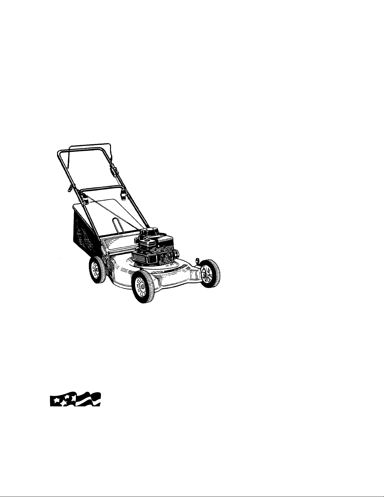
(Model 410 Shown)
Important:
Read Safety Rules
and Instructions Carefully
WARNING: This unit is equipped with an internal combustion engine and should not be used
on or near any unimproved forest-covered, brush-covered or grass-covered land unless the
engine’s exhaust system is equipped with a spark arrester meeting applicable local or state
laws (if any). If a spark arrester is used, it should be maintained in effective working order by
the operator.
In the State of California the above is required by law (Section 4442 of the California Public
Made ^
in
AMERICA
Resources Code). Other states may have similar laws. Federal laws apply on federal lands.
A spark arrester for the muffler is available through your nearest engine authorized service
dealer or contact the service department, P.O. Box 368022, Cleveland, Ohio 44136-9722.
Model Numbers
113-410A000
thru
113-428F000
IMPORTANT!
Record the Model No. and Mfg. Code which
appear on your unit in the space below. You
must have these numbers, along with the date
of purchase, in order to receive warranty or ser
vice.
MEETS ANSI SAFETY STANDARDS
MODEL NO. MFG. CODE
FORM NO. 770-8241H
Page 2

IMPORTANT
THIS SYMBOL POINTS OUT IMPORTANT SAFETY INSTRUCTIONS WHICH, IF NOT FOLLOWED, COULD ENDANGER THE PERSONAL
SAFETY AND/OR PROPERTY OF YOURSELF AND O' HERS. READ AND FOLLOW ALL INSTRUCTIONS IN THIS MANUAL BEFORE
A.
AHEMPTING TO OPERATE YOUR LAWN MOWER. FAILURE TO COMPLY WITH THESE INSTRUCTIONS MAY RESULT IN PERSONAL
INJURY. WHEN YOU SEE THIS SYMBOL— ^
SAFE OPERATION PRACTICES
HEED ITS WARNING.
A
DANGER:
A
with any type of power equipment, careiessness or error on the part of the operator can resuit in serious
injury. If you violate any of Ihese rules, you may cause serious injury to yourseif or others.
TRAINING
Your lawn mower was built to be operated according to the rules for safe operation in this manual. As
1. Read this owner’s guide carefully in its entirety before attempt
ing to assemble or operate this machine. Be completely famil
iar with the controls and the proper use of this machine before
operating it. Keep this manual In a safe place foi future and
regular reference and for ordering replacement parís.
2. Your rotary mower is a precision piece of power equipment,
not a plaything. Therefore, exercise extreme CcUtion at all
times. Your unit has been designed to perform one job: to
mow grass. Do not use it for any other purpose.
3. Never allow children under 14 years old to operite a power
mower. Children 14 years old and over should cniy operate
mower under close parental supervision. Only parsons well
acquainted with these rules of safe operation should be
allowed to use your mower.
4. Keep the area of operation clear of all persons, particularly
small children and pets. Stop engine when they are in the
vicinity of your mower to help prevent blade contad or thrown
object injury. Although the area of operation should be com
pletely cleared of foreign objects, an object maj have been
overlooked and could be accidentally thrown by tt e mower in
any direction and cause serious personal injury to :he operator
or any others allowed in the area.
PREPARATION
1. Thoroughly inspect the area where the equipm ¡nt is to be
used. Remove all stones, sticks, wire, bones and ether foreign
objects which could be picked up and thrown by tlie mower in
any direction and cause serious personal injury to :he operator
or any others allowed in the area. Plan your mowir g pattern to
avoid discharge of material toward roads, sidewalks,
bystanders and the like.
2. Always wear safety glasses or eye shields during Dperation or
while performing an adjustment or repair, to protect eyes from
foreign objects that may be thrown from the machine in any
direction.
3. Wear sturdy, rough-soled work shoes and close-1 itting slacks
and shirts. Shirts and pants that cover the arms í nd legs and
steel-toed shoes are recommended. Do not wear loose fitting
clothes or jewelry. They can be caught in moving parts. Never
operate a unit in bare feet, sandals, or sneakers.
4. Before working with gasoline, extinguish all cigan ties, cigars,
pipes and other sources of ignition. Check the fuel level before
starting the engine. Gasoline is an extremely flammable fuel.
Do not fill the gasoline tank indoors, while the er gine is run
ning, or until engine has been allowed to cool for at least two
minutes after running. Replace gasoline cap securdy and wipe
off any spilled gasoline before starting the engir e as it may
cause a fire or explosion.
5. Disengage the self-propelled mechanism or drh e clutch on
units so equipped before starting the engine.
6. The blade control handle Is a safety device. Never attempt to
bypass its operation. Doing so makes the safety device inoper
ative and may result in personal injury through cor tact with the
rotating blade. The blade control handle must ope ate easily in
both directions and automatically return to the disengaged
position when released.
7. Never attempt to make a wheel or cutting heigh adjustment
while the engine is running.
8. Never operate the mower in wet grass. Always be sure of your
footing. A slip and fall can cause serious personal injury. Keep
a firm hold on the handle and walk, never run. Vlow only in
daylight or in good artificial light.
9. For your safety, use the slope gauge included as part of this
manual to measure slopes before operating this unit on a
sloped or hilly area. If the slope is greater than 15° as shown
on the slope gauge, do not operate this unit on that area or
serious injury could result.
OPERATION
1. Do not change the engine governor settings or overspeed the
engine. Excessive engine speeds are dangerous.
2. Do not put hands or feet near or under rotating parts. Keep
clear of the discharge opening at all times as the rotating blade
can cause injury.
3. Stop the blade when crossing gravel drives, walks or roads.
4. After striking a foreign object, stop the engine, remove the wire
from the spark plug, and thoroughly inspect the mower for any
damage. Repair the damage before restarting and operating the
mower.
5. If the equipment should start to vibrate abnormally, stop the
engine and check immediately for the cause. Vibration is gen
erally a warning of trouble.
6. Shut the engine off and wait until the blade comes to a com
plete stop before removing the grass catcher or unclogging the
chute. The cutting blade continues to rotate for a few seconds
after the engine is shut off. Never place any part of the body in
the blade area until you are sure the blade has stopped rotat
ing.
Before cleaning, repairing or inspecting, make certain the blade
7.
and all moving parts have stopped. Disconnect the spark plug
wire, and keep the wire away from the spark plug to prevent
accidental starting.
Do not run the engine indoors.
8.
Never cut grass by pulling mower toward you. Mow across the
9.
face of slopes, never up-and-down. Exercise extreme caution
when changing direction on slopes. Do not mow excessively
steep slopes. Always be sure of your footing. A slip and fall can
cause serious personal injury.
10. Never operate mower without proper guards, plates or other
safety protective devices in place.
11. Muffler and engine become hot and can cause a burn. Do not
touch.
12. Do not operate this mower with the chute door open, unless
the complete grass catcher or chute deflector is properly
mounted on the mower.
MAINTENANCE AND STORAGE
1. Check the blade and engine mounting bolts at frequent inter
vals for proper tightness. Also visually inspect blade for dam
age (e.g. bent, cracked). Replace with blade which meets origi
nal equipment specifications.
2. Keep all nuts, bolts, and screws tight to be sure the equipment
is in safe working condition.
3. Never store the mower with gasoline in the tank or gas con
tainers inside of a building where fumes may reach an open
flame or spark (e.g. gas hot water heater). Allow the engine to
cool before storing in any enclosure.
4. To reduce fire hazard, keep the engine free of grass, leaves and
excessive oil.
5. Check the grass catcher bag frequently for wear or deteriora
tion. Replace a worn or damaged bag immediately. For safety
protection, replace only with new bag meeting original equip
ment specifications.
Page 3
SET-UP INSTRUCTIONS
IMPORTANT: This unit is shipped WITHOUT
GASOLINE or OIL in the engine. Be certain to ser
vice engine with gasoline and oii before operating
your mower.
NOTE: Reference to right or left hand side of the
mower is observed from the operating position.
TO REMOVE MOWER FROM CARTON
Remove the carton inserts (if any). Remove any loose
parts which may be in the carton. Lift the mower from
the carton, or cut the corners of the carton and roll the
mower out.
HOW TO SET-UP YOUR LAWN MOWER
(Refer to Figure 1)
1. Disconnect the spark plug wire and move it away
from the spark plug.
2. Remove any cardboard pieces which may be
between the upper and lower handles for shipping
purposes. If there is any packaging (plastic or
cardboard) around the upper handle, remove it.
3. Pull up and back on the upper handle to raise the
handle into the operating position. Make certain
the lower handle is seated securely into the
handle mounting brackets. Tighten the hand
knobs on each side of the handle.
NOTE: Your mower is shipped with the handle in the
higher height position. If you wish to lower the height of
the handle, refer to the Adjustment Section at this time.
4. Remove the hairpin clips from the outer hole in
the weld pins on the handle mounting brackets.
Place the hairpin clips in the Inner hole.
5. The rope guide and wing nut are attached to the
starter rope, on top of the engine. Remove the
wing nut from rope guide. Remove the rope guide
from the starter rope.
6. With the spark plug wire disconnected and
grounded, hold the blade control handle against
the upper handle, and pull the starter rope out of
the engine. Hold the rope guide as shown so the
opening in the rope guide is toward the front of
mower. Slip the rope guide around the starter
rope and into the right side of upper handle using
the hole shown. Secure using the wing nut.
7. Make certain all nuts and bolts are tightened
securely.
FIGURE 1.
Lower
Page 4
FIGURE 2.
Bracket
Assembly
FIGURE 3.
Mulching >
Baffle f
u/r
Discharge
Rear
Door
ATTACHING GRASS CATCHER TO MOWER
NOTE: If your mower is equipped with a mulching
baffle, it is in piace on the mower. To remove the
mulching baffle, lift the rear discharge door on the
-mower. Remove the mulching baffle. See figure 2.
To Attach the Grass Catcher:
1. Lift the rear discharge door on the mower.
2. Place the hooks on the grass catcher into the
slots in the handle bracket assemblies. See figure
------
3. Release the rear discharge door.
To remove the grass catcher, lift the rear discharge
door on the mower. Lift the grass catcher up, out of
the slots in the handle bracket assemblies. Release
the rear discharge door.
WARNING: Never operate the mower
unless the hooks on the grass catcher
A
OPTIONAL CHUTE DEFLECTOR
If your mower is equipped with the optional chute
deflector, refer to page 12 at this time.
are seated in the siots on the handle
bracket assemblies, and the rear dis
charge door rests firmly against the top
of the grass catcher.
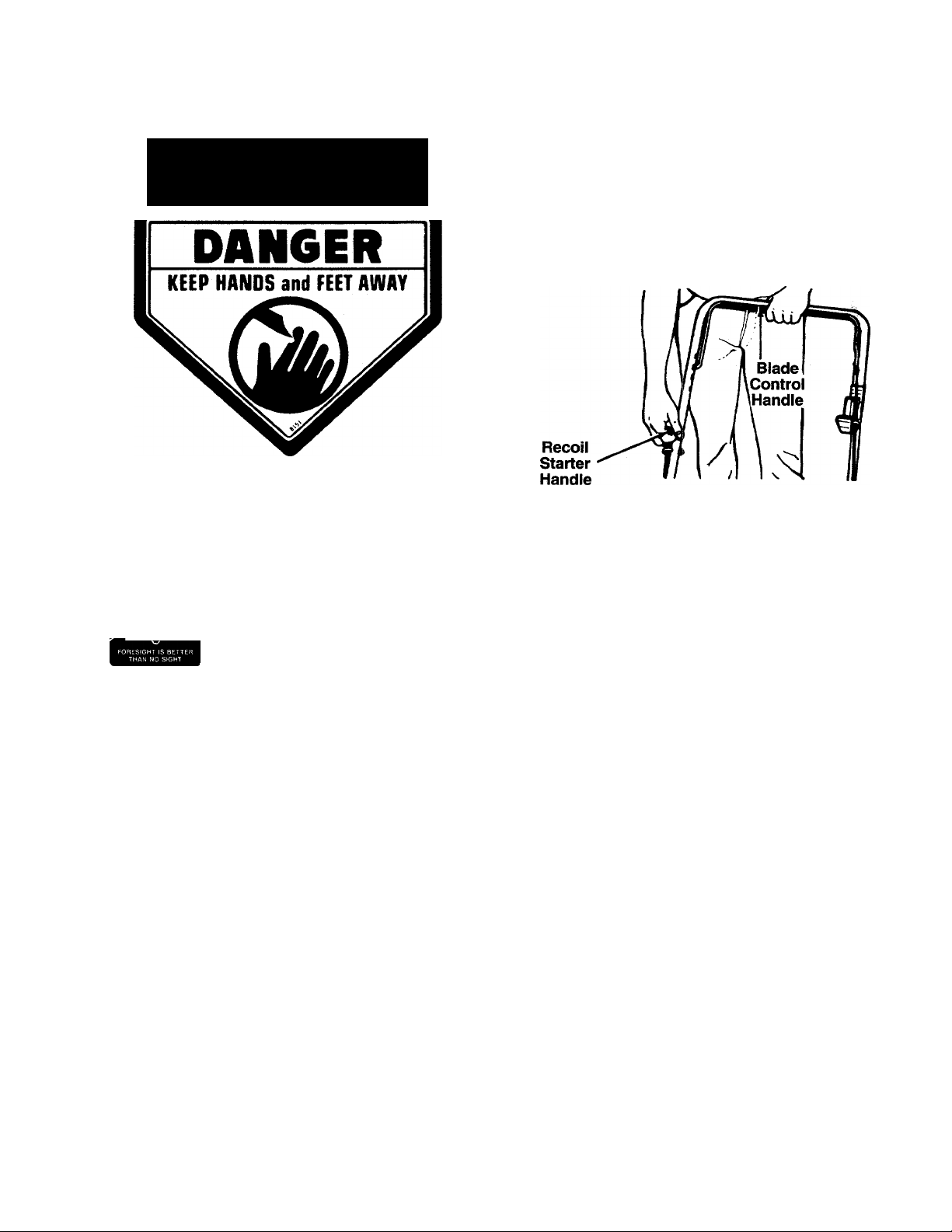
BLADE CONTROL HANDLE
WARNING: This control mechanise is a
safety device. Never attempt to fc ypass
A
its operations.
(CONTROLS
The blade control handle is located on the upper han
dle of the mower. See figure 4. The blade control han
dle must be depressed in order to operate the unit.
Release the blade control handle to stop the engine
and blade.
A
THROHLE CONTROL
The throttle control is located on the side of the upper
handle or on the engine. It is used to regulate the
engine speed.
▲
RECOIL STARTER
The recoil starter handle is attached to the handle.
See figure 4. Stand behind the unit in the operating
position to start the unit.
WARNING: The blade will be rotating whenever the engine is running.
WARNING: The throttle control cannot be used to stop the engine.
Page 5
OPERATION
N
FIGURE 5.
Keep hands and feet away from the chute area on
cutting deck. See figure 5.
The operation of any lawn mower can result in for
N
instructed in the separate engine manuai packed with
your mower. Read instructions carefully.
TO RE D UC E TH E R IS K O F IN JU RY . DO NO T
OPE RA TE MOW ER UNL ES S RE AR T RA I LI NG
SHI EL D AND THIS GUAR D OR ENTI R E
GRA SS C AT CH ER I S IN I T S PR OP ER P LA CE .
eign objects being thrown into the eyes, which
dBBBB can result in severe eye damage.
Always wear safety glasses or eye
shields. We recommend wide vision
safety mask for over spectacles or
standard safety glasses.
GAS AND OIL FILL-UP
Service the engine with gasoline and oil as
6. Pull rope with a rapid, continuous, full arm stroke.
Keep a firm grip on start handle. Return it slowly
to the rope guide.
7. After engine starts, move throttle control to
desired engine speed.
NOTE: If any problems are encountered, refer to the
Trouble Shooting Guide on page 9.
FIGURE 6.
TO STOP ENGINE AND BLADE
1. Release the blade control handle to stop the
engine and blade.
WARNING: The blade continues to rotate
for a few seconds after the engine is shut
A
2. Disconnect the spark plug wire and ground it
USING YOUR ROTARY MOWER
off.
against the engine to prevent accidental starting
while equipment is unattended.
WARNING: Never fill fuel tank indoors,
with engine running or until the engine
A
TO START ENGINE AND ENGAGE BLADE
1. Attach spark plug wire to spark plug.
2. Move throttle control lever all the way forward.
3. Prime engine as instructed in the separate engine
4. Standing behind the unit, depress the blade con
5. Grasp starter handle and pull rope out slowly until
has been allowed to cool for at least two
minutes after running.
manual.
trol handle and hold it against the upper handle
as shown. See figure 6.
engine reaches start of compression cycle (rope
will pull slightly harder at this point). Let the rope
rewind slowly.
WARNING: Never operate your unit with
out either the rear deflector or entire
A
Be sure that lawn is clear of stones, sticks, wire, or
other objects which could damage lawn mower or
engine. Such objects could be accidentally thrown by
the mower in any direction and cause serious person
al injury to the operator and others.
For the best results, do not cut wet grass because it
tends to stick to the underside of the mower, prevent
ing proper discharge of grass clippings, and could
cause you to slip and fall. New grass, thick grass or
wet grass may require a narrower cut. Blade speed
should be adjusted to the condition of the lawn.
For a healthy lawn, never cut more than one-third
of the total length of the grass at any one cutting.
Lawn should be cut in the fall as long as there is
growth.
grass catcher assembly in place.
Page 6

This mower is designed to be operated at full throttle
to give you the best cut and do the most effective job
of bagging the cut grass.
WARNING: If you strike a foreign object,
stop the engine. Remove wire from spark
A
USING THE OPTIONAL MULCHER
For effective mulching, do not cut wet grass because
it tends to stick to the underside of the deck, prevent
ing proper mulching of grass clippings. New Dr thick
grass may require a narrower cut. The ground speed
should be adjusted to the condition of the lawn. If
mowing has been delayed and the grass hes been
allowed to grow in excess of 4“, mulching is not rec
ommended. Mow using the grass bag to red jce the
grass height to 3-1/4" maximum before mulching.
piug, thoroughiy inspect the mower for
any damage, and repair the damage
before restarting and operating the
mower. Extensive vibration of the mower
during operation is an indication of dam
age. The unit shouid be pr(>mptiy
inspected and repaired.
HANDLE HEIGHT ADJUSTMENT
Your mower is shipped with the handle in the higher
height position. To lower the handle height, proceed
as follows.
1. Remove the starter rope from the rope guide.
2. Remove the upper handle by removing the hand
knobs and carriage bolts. Lay the upper handle
out of the way, being careful not to bend or kink
the cables.
3. Remove the hairpin clips from the weld pins on
the handle brackets. Press outward on the legs of
the lower handle, and remove it from the mower.
4. Turn the lower handle around so the flat on the
bottom is facing upward as shown in figure 8.
Reassemble, placing the bottom holes in the han
dle over the weld pins in the handle mounting
bracket.
5. Reassemble the upper handle.
6. Place the hairpin clips in the inner holes in the
weld pins and attach the starter rope as instruct
ed in the Set-Up Instructions.
ADJUSTMENTS
WARNING: Do not at any time make any
adjustment to lawn mower without first
A
CUTTING HEIGHT ADJUSTMENT
An adjusting plate and thumb lever at eacf wheel
position provides cutting height adjustment Each
adjusting plate has nine height positions. Height of cut
will be changed when the thumb lever is mov id from
one hole to another. Simply depress the lever owards
wheel and move wheel and lever assembly to desired
position. All wheels must be placed in the sane rela
tive position. See figure 7.
FIGURE 7.
stopping engine and disconnectin(j spark
plug wire.
_____
Flat
FIGURE 8.
THROTTLE CONTROL ADJUSTMENT
If the throttle control needs adjustment or if it has
been replaced, adjust as follows.
1. Remove the screw shown in figure 9. Remove the
cable clamp from the cable.
NOTE: /fyou have a Tecumseh engine, simply loosen
the screw shown in figure 9B so the cable will move
freely beneath the clamp. It is not necessary to
remove the screw and clamp completely.
2. Push the throttle control lever on the handle all
the way forward as far as it will go, then back it off
one “click.” Make certain the throttle control
lever remains in this position.
3. Push the control lever on the engine as far toward
the rear of the engine as it will go. Secure the
cable in this position with the cable clamp and
screw.
Page 7

Biade Control—Lubricate the pivot points on the
blade control handle and the brake cable at least
N
once a season with light oil. See figure 10. The blade
control must operate freely in both directions.
Blade Control
Handle
Pivot
Point
Cable
Control
Lever
On Engine
FIGURE 9B.—Tecumseh Engines
CARBURETOR ADJUSTMENTS
WARNING: If any adjustments are made
to the engine while the engine is running
A
Minor carburetor adjustments may be required to
compensate for differences in fuel, temperature,
altitude and load. To adjust carburetor, refer to the
separate engine manual packed with your mower.
NOTE: A dirty air cleaner will cause an engine to run
rough. Be certain air cleaner is clean and attached to
the carburetor before adjusting carburetor.
(e.g. carburetor), keep clear of all moving
parts. Be careful of heated surfaces and
muffler.
Screw
FIGURE 10.
Rear Discharge Door—The torsion springs and pivot
points should be lubricated periodically with light oil to
prevent any rust or binding. Door must work freely.
Wheels—Mower may be provided with ball bearing
wheels. Lubricate at least once a season with light oil.
If the wheels are removed for any reason, lubricate
the surface of the axle bolt and the inner surface of
the wheel with light oil. A 4 oz. plastic bottle of light oil
lubricant is available. Order part number 737-0170.
Engine oil may also be used.
Engine—Follow engine manual for lubrication instruc
tions.
MAINTENANCE
WARNING: Be sure to disconnect and
ground the spark plug wire before per
A
NOTE: When tipping the unit, empty the fuel tank and
keep engine spark plug side up.
TROUBLE SHOOTING
Refer to page 9 of this manual for trouble shooting
information.
forming any repairs or maintenance.
A
LUBRICATION
WARNING: Always stop engine and dis
connect spark plug wire before cleaning,
lubricating or doing any kind of work on
lawn mower.
CUniNG BLADE
When removing the cutting blade for sharpening or
replacement, protect hands by using heavy gloves or
a rag to grasp the cutting blade. Remove the bolt and
bell washer which hold the blade and adapter to the
engine crankshaft. Remove the blade and adapter
from the crankshaft.
If the blade or blade adapter needs replacing, remove
the two small bolts, lock washers and nuts which hold
the blade to the adapter.
Page 8

WARNING: Periodically inspect th(» blade
adapter for cracks, especially if you
A
When sharpening the blade, follow the origins I angle
of grind as a guide. It is extremely important that each
cutting edge receives an equal amount of grir ding to
prevent an unbalanced blade. An unbalanced blade
will cause excessive vibration when rotating at high
speeds, may cause damage to the mower an i could
break, causing personal injury.
It is recommended that the blade always be removed
from the adapter for the best test of balance.
The blade can be tested by balancing it on si round
shaft screwdriver. Remove metal from the heavy side
until it balances evenly.
Before reassembling the blade and the blade adapter
to the unit, lubricate the engine crankshaft Sind the
inner surface of the blade adapter with light oil.
Lubricating the bolt holes, bolts and inner surface of
the nuts with light oil is also recommended. A 4 oz.
plastic bottie of light oil lubricant is avaiiable Order
part number 737-0170. Engine oil may also be jsed.
When replacing the blade, be sure to install tha blade
with the side of the blade marked “Bottom” (or with
part number) facing the ground when the mower is in
the operating position.
strike a foreign object. Replace when
necessary.
Service air cleaner every 25 hours under normal con
ditions. Clean every few hours under extremely dusty
conditions. Poor engine performance and flooding
usually indicates that the air cleaner should be ser
viced. To service the air cleaner, refer to the separate
engine manual packed with your unit.
The spark plug should be cleaned and the gap reset
once a season. Spark plug replacement is recom
mended at the start of each mowing season; check
engine manual for correct plug type and gap specifi
cations.
Clean the engine regularly with a cloth or brush.
Keep the cooling system (blower housing area) clean
to permit proper air circulation which is essential to
engine performance and life. Be certain to remove all
grass, dirt and combustible debris from muffler area.
REAR FLAP REPLACEMENT
The rear flap is attached to the back of the mower
deck, and is designed to minimize the possibility that
objects will be thrown from the rear of the mower
toward the operator. If the rear flap becomes dam
aged, replace as follows.
To remove the old rear flap, cut off the flat end of the
wire rod which secures it to the deck using a pair of
side-cutters. Attach the new rear flap using the new
rod provided with the rear flap, bending the ends of
the rod over to secure.
OFF-SEASON STORAGE"
Blade Mounting Torque
Center Boit: 450 in. lbs. min., 600 in. lbs. max.
Blade Adapter Bolts: 200 in. lbs. min., 350 in. lb a. max.
To insure safe operation of your unit, ail nuts and bolts
must be checked periodically for correct tightness.
DECK
The underside of the mower deck should be c leaned
after each use to prevent a buildup of grass cli apings,
leaves, dirt or other matter. If this debris is allc wed to
accumulate, it will invite rust and corrosion, and may
cause an uneven discharge of grass clippings at the
next cutting.
The deck may be cleaned by tilting the mower and
scraping clean with a suitable tool (make certain the
spark plug wire is disconnected).
ENGINE
Refer to the separate engine manual for engine
maintenance instructions.
Maintain engine oil as instructed in the separate
engine manual packed with your unit. Read an(i follow
instructions carefully.
The following steps should be taken to prepare lawn
mower for storage.
1. Clean and lubricate mower thoroughly as
described in the lubrication instructions.
2. Refer to engine manual for correct engine storage
instructions.
3. Coat mower’s cutting blade with chassis grease
to prevent rusting.
4. Store mower in a dry, clean area. Do not store
next to corrosive materials, such as fertilizer.
NOTE: When storing any type of power equipment in
an unventilated or metai storage shed, care should be
taken to rust-proof the equipment Using a light oil or
silicone, coat the equipment especially cables and all
moving parts.
ATTACHMENTS AVAILABLE
Mulching Kit model 190-082 is available as optional
equipment for the mowers shown in this manual. The
special high lift mulching blade and baffles will pulver
ize the grass clippings, making it unnecessary to bag
the grass.
Chute Deflector model 190-104 is also available.
Page 9

■ N
Trouble
TROUBLE SHOOTING GUIDE
Possible Cause(s)
Corrective Action
Engine fails to start
Engine runs erratic
Engine overheats 1. Engine oil level low.
Occasional skip
(hesitates) at high speed
1. Blade control handle disengaged.
2. Spark plug wire disconnected.
3. Throttle control lever not in CHOKE
or START position.
4. Fuel tank empty, or stale fuel.
5. Blocked fuel line (if so equipped).
6. Faulty spark plug.
7. Engine flooded.
1. Unit running in CHOKE or START
position.
2. Spark plug wire loose.
3. Blocked fuel line (if so equipped)
or stale fuel.
4. Vent in gas cap plugged.
5. Water or dirt in fuel system.
6. Dirty air cleaner.
7. Carburetor out of adjustment.
2. Air flow restricted.
3. Carburetor not adjusted properly.
1. Spark plug gap too close.
2. Carburetor idle mixture adjustment
improperly set.
1. Engage blade control handle.
2. Connect wire to spark plug.
3. Move throttle lever to CHOKE or
START position.
4. Fill tank with clean, fresh gasoline.
5. Clean fuel line.
6. Clean, adjust gap or replace.
7. Remove spark plug, dry the plug, and
crank engine with plug removed and
throttle in off position. Replace spark
plug, connect wire and resume starting
procedures.
1. Move throttle lever to FAST
position.
2. Connect and tighten spark plug wire.
3. Clean fuel line; fill tank with clean,
fresh gasoline.
4. Clear vent.
5. Drain fuel tank. Refill with fresh fuel.
6. Clean air cleaner.f
7. Adjust carburetor.t
1. Fill crankcase with proper oil.
2. Remove blower housing and clean.f
3. Adjust carburetor.t
1. Adjust gap to .030“.
2. Adjust carburetor.t
Idles poorly
Excessive vibration
Mower will not
discharge grass
Uneven cut
1. Spark plug fouled, faulty or gap too wide.
2. Carburetor improperly adjusted.
3. Dirty air cleaner.
1. Cutting blade loose or unbalanced.
2. Bent cutting blade.
1. Engine speed too low.
2. Wet grass.
3. Excessively high grass.
1. Wheels not positioned correctly.
2. Dull blade.
1. Reset gap to .030" or replace spark plug.
2. Adjust carburetor.t
3. Clean air cleaner.f
1. Tighten blade and adapter.
Balance blade.
2. Replace blade.
1. Set throttle between 3/4 and full throttle.
2. Do not mow when grass is wet; wait until
later to cut.
3. Mow once at a high cutting height, then
mow again at desired height or make a
narrower cutting swath (1/2 width).
1. Place all four wheels in same
height position.
2. Sharpen or replace blade.
fRefer to separate engine manual packed with your unit.
Note: For repairs beyond the minor adjustments listed above, contact your local authorized service dealer.
NOTE: The use of any accessory on this Rotary Mower other than those manufactured by the mower manufac
turer is not recommended.
WARNING: DO NOT operate the mower without the entire grass catcher or rear discharge door
in place. DO NOT operate the mower without the protective shield on the rear of the deck in
A
place.
NOTE: Under normal usage bag material is subject to wear and should be checked periodically. Be sure any
replacement bag complies with the mower manufacturer’s recommendations.
9
Page 10

I
I
Models 410 thru 428
NOTE: The engine is not under warranty by the
mower manufacturer. . .If repairs or service is
needed on the engine, please contact your
nearest authorized engine
service outlet. Check the
“Yellow Pages” of your
telephone book under
“Engines-Gasollne.”
Find It Fast
In The
Yellow Pages
COMPLETE GRASS CATCHER
Soft Top— Model 190-088-000
Hard Top— Model 190-091-000
ATTACHMENTS AVAILABLE
Mulching Kit— Model 190-099-000
Chute Deflector— Model 190-104-000
**WHEEL CHART Bar Tread “S” Wave Tread
Wheels w/o Bearings 734-1781
734-1512A (8"-Gray)
(No Hub Cap)
634-0020
(Uses Hub Cap)
Wheels with Ball Brgs.f
(Brg. Part No. 741-0484)
734-1513B (8"-Gray)
734-1517B (8"-Beige)
fRequire Wave Washer 736-0504
10
*Optional Hub Caps
Description Part No.
Gray (5-1/2" Dia.)
Beige (5-1/2" Dia.)
Gray (3-1/2" Dia.)
Black (1-1/2" Dia.)
Red (1-3/8" Dia.)
731-0981A
731-0982A
720-0249
720-0251
731-0342
Page 11

PARTS LIST FOR MODELS 410 THRU 428 ROTARY MOWERS
REF.
NO.
, 1 747-0824
PART
NO.
CODE DESCRIPTION
Control Handle Ass’y- (Std.)
REF.
NO.
PART
NO.
34 736-0452 Bell-Wash. .39" I.D.
647-0004 Control Handle Ass’y. (Deluxe) (Used w/Keyed Adapter)
2 710-1205 Rope Guide 736-0453
712-0397 Wing Nut 1/4-20 Thd. (Used w/Splined Adapter)
3
4 710-1174
6 720-0276
7 710-0605
8 736-0501
712-0324
9
10 746-0876
11 749-0538C
12 720-0226 Foam Grip (Optional)
749-0928
13
14
726-0240
764-0310
15
16 746-0550
746-0552 Control Cable—49" (413, 415, 48
Curved Hd. Bolt 5/16-18 x
2" Lg.
N
Hand Knob
Oval C-Sunk Mach. Scr. 37
Spr. Wash. .66" I.D. 38
Hex L-Nut 1/4-20 Thd. 39
35 710-1055 Hex Bolt 3/8-24 x 1" Lg.
742-0621
36
742-0721 N
736-0169 L-Wash. 3/8" I.D.*
712-0241
736-0356
Throttle Lever 40 712-0798
Upper Handle 41 15261A
42 15262B
N Lower Handle 43 14832
Cable Tie 44
Rear Catcher Frame
738-0507B
45 736-0105 Bell-Wash. .38" I.D. x .88" O.D.
Control Cable—39" (410, 412, 46 738-0102 Axle Bolt
423, 425)
47
720-0190 Spring Lever Knob
732-0417A
423, 425) 49 14578 Height Adj. Ass’y. Comp.—R.H.
746-0553
Control Cable—36" (414, 416, 14579
418, 424, 426, 428)
17 746-0842
746-0845
Throttle Control Wire—51" 14765
(410, 412, 420, 422) 51
782-5002
Throttle Control Wire—45" 52 710-0654
(413, 415, 423, 425)
746-0843
Throttle Control Wire—55" 53 782-5003 Rear Baffle
(414, 416, 418, 424,426,
54 710-1017
428) .62" Lg.
18 764-0311
Front Catcher Frame 55 710-0892
1 19 764-0309 Grass Bag
714-0104 Int. Cotter Pin 5/16" Dia. 56 682-0516 N Handle Brkt. Ass’y.—R.H.
20
21 732-0678
22 732-0677
23 782-7000
24
751-0568
25 746-0875 Throttle Body
26 811-00185
27
28
—
710-1237 Hex Wash. Hd. Scr. #10-32 x
Door Spring—R.H. 57 682-0515 N Handle Brkt. Ass’y.—L.H.
Door Spring—L.H.
Rear Discharge Door 59
Cable Clamp (B&S) 60
782-0310 21" R.D. Deck
58
**
**
61 764-0433
Throttle Box Comp. (Incl. Ref. 7,
8, 9, 10, 25)
62 731-1322
63 710-0286 Pan Hd. Mach. Scr. 1/4-20 x .5"
Engine
64 712-0324
.62" Lg. (B&S) 65 782-9011
29 735-0639
30 732-0700
31 731-1236
Spark Plug Boot (Optional) 66
Wire Rod
Rear Flap 68 731-1405 N Deflector
782-5007
67 782-5004
32 753-0484 Blade Adapter Kit (Keyed) 69 711-0996
753-0485
710-1044 Hex Bolt 3/8-24 x 1.5" Lg.
33
710-0757
Blade Adapter Kit (Splined) 70 726-0201 Push Speed Nut
71 710-0192
(Used w/Keyed Adapter)
72 720-0275 Knob
Hex Bolt 7/16-20 X 1.5" Lg.
(Used w/Splined Adapter)
CODE
Bell-Wash. .46" I.D.
N 21" Blade
21" Mulching Blade (Optional)
Hex Nut 3/8-24 Thd.
Bell-Wash. .39" I.D. x 1.38"
Hex Nut 3/8-16 Thd.*
Height Adj. Plate
Pivot Bar
Spring Lever Ass’y. w/Knob
ShId. Bolt .5" Dia. x .357"
Spring Lever
Height Adj. Ass’y. Comp.—L.H.
(Not Shown) , . /
Pivot Barg,fx
Front Baffle
Hex L-Wash. Hd. Scr. 3/8-16 x
1" Lg.
Torx Mach. AB-Tap Scr. 1/4 x
Hex L-Wash. Hd. AB-Tap Scr.
1/4 X .62" Lg.
Wheel Ass’y. Comp.
Hub Cap
Grass Bagtt
Hard Top Coverft
Lg.tt
Hex Nylon L-Nut 1/4-20 Thd.tt
Mounting Bracketft
Mulching Baffle Plug (Optional)
Mulching Baffle—R.R. (Optional)
N
Rod
Truss Scr. #10-24 X .38" Lg.
DESCRIPTION
tModels 410 thru 418 only.
ttModels 420 thru 428 only.
*For faster service obtain standard nuts, bolts and washers locally.
If these items cannot be obtained locally, order by part number
and size as shown on parts list.
NOTE: This instruction manual covers various models, and all
specifications shown do not necessarily apply to your model.
Specifications subject to change without notice or obligation.
CODE: N notates a new part (not previously existing).
COLOR: A three digit number is the color code. Specify color
code if color or finish is important when ordering parts, [i.e.,
(part no.)-638 for Red Finish]
Color Codes
436—Radiant Yellow
460—Green Flake 640—Green
483—Charcoal Gray 646—CM Blue
498—Yellow 650—Red Metallic
499—Beige
629—Silver Flake
637—Black
638—Red
657—Teal
663—Dark Teal
11
Page 12

OPTIONAI. CHUTE DEFLECTOR
Tab
Push
Nut
If your mower is equipped with the optional chute
deflector, assemble as follows.
1. Slide the rod into the upper edge of the chute
deflector so the welded tab on the rod is toward
the left side of the chute deflector. When assem
bled correctly, the rod will extend further to the left
------
side than the right side. See figure A.
2. Slide the push nut onto the right side of the rod to
secure.
ATTACHING CHUTE DEFLECTOR TO MOWER
Lift the rear discharge door on the mower. Place the
ends of the rod into the slots in the handle bracket
-assemblies. See figure B. Release the rear discharge
door.
To remove the chute deflector, lift the rear discharge
door on the mower. Lift the chute deflector up, out of
the slots in the handle bracket assemblies. Release
the rear discharge door.
12
Page 13

USE THIS PAGE AS A GUIDE TO DETERMINE SLOPES WHERE YOU MAY NOT OPERATE SAFELY.
SIGHT AND HOLD THIS LEVEL WITH A VERTICAL TREE
o
cs
LU
...........
---------------^
--------------------------------
.
.....................
'
.............................
A POWER POLE
....
n '
A CORNER OF A BUILDING
OR A FENCE POST
I *
.........
^
I ,,
I
I
rk-" ' n~---------------------------TV
.......... iSo ^
-------------
........
...
****••»,
CO
CO
▲c WARNING I
Do not mow on inclines with a slope in excess of 15 degrees (a rise of approximately 2-1/2 feet every 10 feet). A
riding mower could overturn and cause serious injury. If operating a walk-behind mower on such a slope, it is
extremely difficult to maintain your footing and you could slip, resulting in serious injury.
Operate RIDING mowers up and down slopes, never across the face of slopes.
Operate WALK-BEHIND mowers across the face of slopf -«ver up and down slopes.
Page 14

11
Page 15

Page 16

11
MANUFACTURER’S
LIMITED
WARRANTY
THE MTD TWO YEAR SUPREME WARRANTY:
For TWO YEARS from the dat ì of retail purchase within the United States of America,
its possessions and territories. MTD PRODUCTS INC will, at its option, repair or
replace, for the original purchaser, free of charge, any part or parts found to be defec
tive in material or workmanship. This warranty covers units which have been operated
and maintained in accordance with the owner’s instructions furnished with the unit,
and which have not been subject to misuse, abuse, commercial use, neglect, accident,
improper maintenance or altera tion. Normal wear parts or components thereof are sub
ject to separate terms as noted below in the “NO FAULT Ninety Day Consumer
Warranty” clause.
NO FAULT Ninety Day Consumer Warranty on Normal Wear Parts: All normal wear
part failures will be covered on this product for a period of 90 days regardless of cause. After 90 days,
but within the two year warranty peri 3d, normal wear part failures will be covered if caused by defects
in material or workmanship of othe ■ component parts. Normal wear parts are defined as batteries,
belts, blades, blade adapters, grass ba js, rider deck wheels, seats and tires.
How to Obtain Service: Warrant / service is available, with proof of purchase, through your local
authorized service dealer or distribuì 3r. To locate the dealer or distributor in your area, please check
the yellow pages or contact the Cusiomer Service Department of MTD PRODUCTS INC, P.O. Box
368022, Cleveland, Ohio 44136-9722, phone (216) 225-7711. The return of a complete unit will not be
accepted by the factory unless prior ■ vritten permission has been extended by the Service Department
of MTD PRODUCTS INC.
Transportation Charges: Transportation charges for the movement of any power equipment unit
or attachment are the responsibility o ' the purchaser. Transportation charges for any part submitted for
replacement under this warranty mus be paid by the purchaser unless such return is requested in writ
ing by MTD PRODUCTS INC.
Units Exported Out of the Unit« d States: MTD PRODUCTS INC does not extend any warranty
for products sold or exported outside of the United States of America, its possessions and territories,
except, those sold through MTD’s authorized channels of export distribution.
Other Warranties:
1. The engine or motor or component parts thereof carry separate warranties from their manu
facturers. Please refer to the appi:cable manufacturer’s warranty on these items.
2. Log splitter pumps, valves and cylinders or component parts thereof are covered by a one year
warranty.
All other warranties, express o * implied, including any implied warranty of merchantability
or fítness for a particular purpi »se are hereby expressly disclaimed in their entirety.
4. The provisions as set forth in
PRODUCTS INC’s obligations a
not be liable for incidental or c<
How State Law Relates to Thi
rights, and you may also have other
allowed in some states and therefore t
Note: This warranty does not cover:
ening and tune-ups, or adjustments st
Nor does this warranty cover normal i
1
his warranty provide the sole and exclusive remedy of MTD
rising from the sale of its products. MTD PRODUCTS INC will
insequential loss or damage.
s Warranty: This limited warranty gives you specific legal
ights which vary from state to state. Certain disclaimers are not
hey may not apply to you under all circumstances.
outine maintenance items such as lubricants, filters, blade sharp
ed as brake adjustments, clutch adjustments or deck adjustments,
leterioration of the exterior finish due to use or exposure.
ww~
11
mm”*
li
MTD PRODUCTS INC • P.O. Box 368022 • Cleveland, Ohio 44136-9722
 Loading...