

Page 1
OWNEirS GUIDE
• ASSEMBLY • OPERATION • MAINTENANCE • PARTS •
20" and 22"
ROTARY
MOWERS
$1.00
Important:
Read Safety Rules
and Instructions Carefully
WARNING; This unit is equipped with an internal combustion engine and should not be used
on or near any unimproved forest-covered, brush-covered or grass-covered land unless the
engine’s exhaust system is equipped with a spark arrester meeting applicable local or state
laws (if any). If a spark arrester is used, it should be maintained in effective working order by
the operator.
In the State of California the above is required by law (Section 4442 of the California Public
Made ^
in
AMERICA
Resources Code). Other states may have similar laws. Federal laws apply on federal lands.
A spark arrester for the muffler is available through your nearest engine authorized service
dealer or contact the service department, P.O. Box 368022, Cleveland, Ohio 44136-9722.
Model Series
113<030A000 thru 113-032D000
113-040A000 thru 113-042D000
113-050A000 thru113-052D000
113-060A000 thru 113-062D000
IMPORTANT!
Record the Model No. and Mfg. Code which
appear on your unit in the space below. You
must have these numbers, along with the date
of purchase, in order to receive warranty or ser
vice.
MEETS ANSI SAFETY STANDARDS
MODEL NO. MFG. CODE
FORM NO. 770-8238H
Page 2

IMPORTANT
THIS SYMBOL POINTS OUT IMPORTANT SAFETY INSTRUCTIONS WHICH, IF NOT FOLLOWED, COULD ENDANGER THE PERSONAL
SAFETY AND/OR PROPERTY OF YOURSELF AND CTHERS. READ AND FOLLOW ALL INSTRUCTIONS IN THIS MANUAL BEFORE
▲
ATTEMPTING TO OPERATE YOUR LAWN MOWER. F\ILURE TO COMPLY WITH THESE INSTRUCTIONS MAY RESULT IN PERSONAL
INJURY. WHEN YOU SEE THIS SYMBOL— Д
Your lawn mower was built to be operated according to tbe rules lor safe operation in this manual. As
DANGER:
A
TRAINING
1. Read this owner’s guide carefully in its entirety befot 3 attempt
ing to assemble or operate this machine. Be compie teiy famiiiar with the controls and the proper use of this mact ine before
operating it. Keep this manual in a safe place for uture and
regular reference and for ordering replacement parts
2. Your rotary mower is a precision piece of power equipment,
not a plaything. Therefore, exercise extreme caution at all
times. Your unit has been designed to perform one job: to
mow grass. Do not use it for any other purpose.
3. Never allow children under 14 years old to operat3 a power
mower. Children 14 years old and over should only operate
mower under close parental supervision. Only peisons well
acquainted with these rules of safe operation should be
allowed to use your mower.
4. Keep the area of operation clear of all persons, particularly
small children and pets. Stop engine when they are in the
vicinity of your mower to help prevent blade contact or thrown
object injury. Although the area of operation shouti be com
pletely cleared of foreign objects, an object may nave been
overlooked and could be accidentally thrown by the mower in
any direction and cause serious personal injury to the operator
or any others allowed in the area.
PREPARATION
1. Thoroughly inspect the area where the equipmeit is to be
used. Remove all stones, sticks, wire, bones and other foreign
objects which could be picked up and thrown by thf mower in
any direction and cause serious personal injury to tfe operator
or any others allowed in the area. Plan your mowing pattern to
avoid discharge of material toward roads, s dewalks,
bystanders and the like.
2. Always wear safety glasses or eye shields during operation or
while performing an adjustment or repair, to protect eyes from
foreign objects that may be thrown from the mad ine in any
direction.
3. Wear sturdy, rough-soled work shoes and close-fit ;ing slacks
and shirts. Shirts and pants that cover the arms and legs and
steel-toed shoes are recommended. Do not wear l( ose fitting
ciothes or jeweiry. They can be caught in moving p irts. Never
operate a unit in bare feet, sandals, or sneakers.
4. Before working with gasoline, extinguish all cigaretes, cigars,
pipes and other sources of ignition. Check the fuel I jvel before
starting the engine. Gasoline is an extremely flammable fuel.
Do not fill the gasoline tank indoors, while the engine is run
ning, or until engine has been allowed to cool for ct least two
minutes after running. Replace gasoline cap securel/ and wipe
off any spilled gasoline before starting the engine as it may
cause a fire or expiosion.
5. Disengage the self-propelled mechanism or drive clutch on
units so equipped before starting the engine.
6. The blade control handle is a safety device. Never attempt to
bypass its operation. Doing so makes the safety de\ ice inoper
ative and may result in personal injury through contact with the
rotating blade. The blade control handle must operjte easily in
both directions and automatically return to the c isengaged
position when released.
7. Never attempt to make a wheel or cutting height idjustment
while the engine is running.
8. Never operate the mower in wet grass. Always be s jre of your
footing. A slip and fall can cause serious personal i ijury. Keep
a firm hold on the handle and walk, never run. Mow only in
daylight or in good artificial light.
with any type of power equipment, carelessness or error on the part of the operator can result in serious
injury. If you violate any o' these rules, you may cause serious injury to yourself or others.
SAFE OPERATION PRACTICES
НЕЕ ) ITS WARNING.
OPERATION
5.
7.
10.
11.
MAINTENANCE AND STORAGE
1. Check the blade and engine mounting bolts at frequent inter
2. Keep all nuts, bolts, and screws tight to be sure the equipment
3. Never store the mower with gasoline in the tank or gas con
4. To reduce fire hazard, keep the engine free of grass, leaves and
5. Check the grass catcher bag frequently for wear or deteriora
A
For your safety, use the slope gauge included as part of this
manual to measure slopes before operating this unit on a
sloped or hilly area. If the slope is greater than 15° as shown
on the slope gauge, do not operate this unit on that area or
serious injury couid result.
Do not change the engine governor settings or overspeed the
engine. Excessive engine speeds are dangerous.
Do not put hands or feet near or under rotating parts. Keep
clear of the discharge opening at ail times as the rotating biade
can cause injury.
Stop the blade when crossing gravel drives, walks or roads.
After striking a foreign object, stop the engine, remove the wire
from the spark plug, and thoroughly inspect the mower for any
damage. Repair the damage before restarting and operating the
mower.
If the equipment should start to vibrate abnormally, stop the
engine and check immediately for the cause. Vibration is gen
erally a warning of troubie.
Shut the engine off and wait until the blade comes to a com
plete stop before removing the grass catcher or unclogging the
chute. The cutting blade continues to rotate for a few seconds
after the engine is shut off. Never place any part of the body in
the blade area until you are sure the blade has stopped rotat
ing.
Before cleaning, repairing or inspecting, make certain the blade
and all moving parts have stopped. Disconnect the spark plug
wire, and keep the wire away from the spark plug to prevent
accidental starting.
Do not run the engine indoors.
Never cut grass by pulling mower toward you. Mow across the
face of slopes, never up-and-down. Exercise extreme caution
when changing direction on slopes. Do not mow excessively
steep slopes. Always be sure of your footing. A slip and fall can
cause serious personal injury.
Never operate mower without proper guards, plates or other
safety protective devices in place.
Muffler and engine become hot and can cause a burn. Do not
touch.
vals for proper tightness. Also visually inspect blade for dam
age (e.g. bent, cracked). Replace with blade which meets origi
nal equipment specifications.
is in safe working condition.
tainers inside of a building where fumes may reach an open
flame or spark (e.g. gas hot water heater). Allow the engine to
cool before storing in any enclosure.
excessive oil.
tion. Replace a worn or damaged bag immediately. For safety
protection, replace only with new bag meeting original equip
ment specifications.
Page 3
------- i---------------------------------------------------------------------
cut Alor.j, ^is Line
--------------------------------------------------------------------^-------------
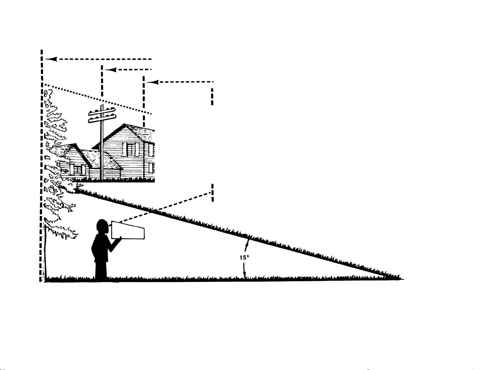
USE THIS SHEET AS A GUIDE TO DETERMINE SLOPES WHERE YOU MAY NOT OPERATE SAFELY.
SIGHT AND HOLD THIS LEVEL WITH A VERTICAL TREE
A POWER POLE
A CORNER OF A BUILDING
7s
OR A FENCE POST
(D
(D
T3
■o
0)
0)
□r
(D
(D
3
0)
(0
fi}
<D
0)
O
(D
C
c
o
—I
<0
(D
<D
3
o
<D
CO
"O
m
O
O
.................
I
u
WARNING
.......
.
SiQp
...i. . -
AC
Do not mow on inclines with a siope in excess of 15 degrees (a rise of approximately 2-1/2 feet every 10 feet). A
riding mower couid overturn and cause serious injury, if operating a waik-behind mower on such a slope, it is
extremely difficult to maintain your footing and you couid siip, resulting in serious injury.
Operate RIDiNG mowers up and down slopes, never across the face of slopes.
Operate WALK-BEHIND mowers across the face of slopes, never up and down slopes.
Page 4
11
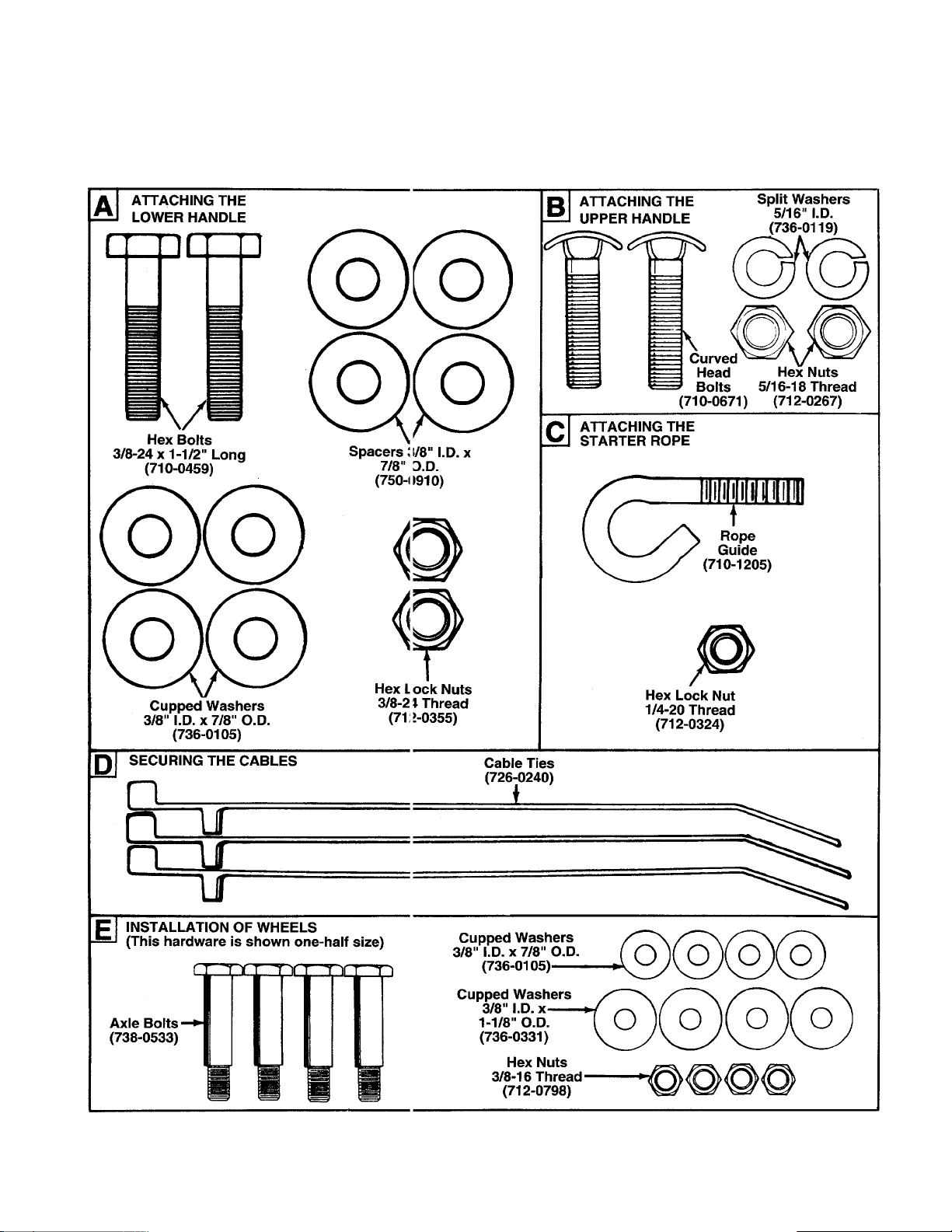
CONTENTS OF HARDWARE PACK
Remove this sheet from your owner’s manual and lay the hardware on the illustration for identification purposes. After assembiy, keep the Slope Gauge which is on the reverse s ide of this sheet for future use.
(Hardware pack may contain extra items which are not used on your unit. Part numbers are shown in parentheses.)
O
c
>
c'
0
INCHES
I I
I
I I I I I I I I I I I I I I I I I I I
I
Page 5
ASSEMBLY INSTRUCTIONS
IMPORTANT: This unit is shipped WITHOUT GASOLINE
or OIL. After assembly, service engine with gasoiine
and oii as instructed in the separate engine manuai
packed with your unit.
NOTE: Reference to right or left hand side of the mower is
obsen/ed from the operating position.
Toois Required for Assembiy
(1) 1/2" Wrench
(2) 9/16" Wrenches
(1) Phillips Screwdriver
(1) Adjustable Wrench
(Two 6" Adjustable Wrenches may be used instead of the
above.)
Lower
Handle
Use
This
Hole
Rear Baffle
(Models 040 thru
Crowned 1
Side \
(Cupped
i Side
Onhi);.;.
Axle Bolt
Hex Nut
Cupped This',
Washer Hole
FIGURE 1.—Models 040 thru 042 Shown
Use
Hex Nut
Cupped
Washer
Spacer
UNPACKING
1. Remove the lawn mower from the carton by opening
the top flaps and lifting the unit out. Be careful of the
staples. Make certain all parts and literature have been
removed from the carton before the carton is discarded.
2. Disconnect and ground the spark plug wire against the
engine.
3. Stretch out the control cables behind the mower and
place on the floor. Be careful not to bend or kink the
cables at any time during assembly.
4. Remove page four from this manual and lay the contents
of the hardware pack on the illustration for identification.
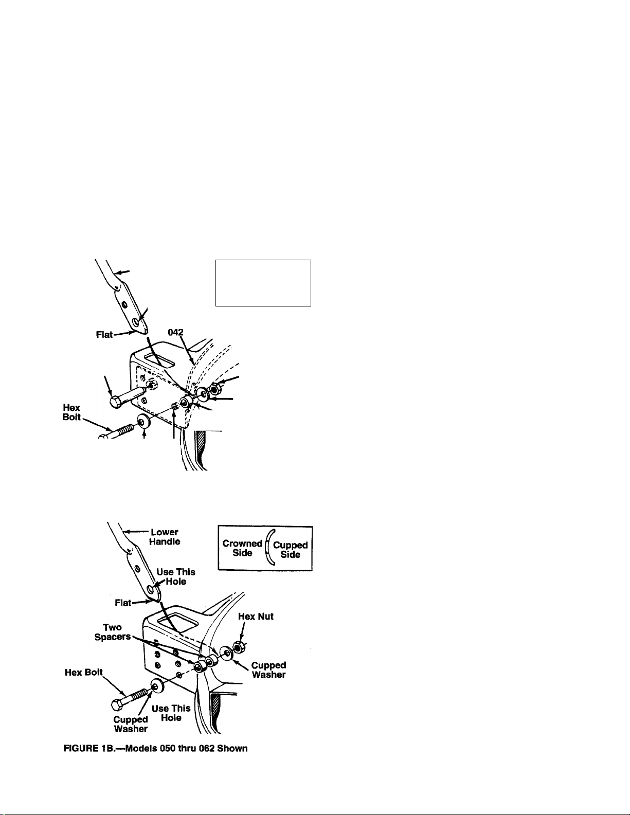
NOTE: ALL MODELS—The handle on your mower can be
adjusted to two different height settings. To raise the height
of the handle attach the lower handle so that the flat part of
the handle is facing downward, as shown in figure 1 and 1B.
To lower the height of the handle rotate handle so that the
flat part of the handle faces upward.
ATTACHING THE LOWER HANDLE (Hardware A)
Models 030 thru 042 only:
1. Raise the rear of the deck and block securely.
2. Models 040 through 042 only: Place the rear baffle in
position inside the rear of the deck. Use one axle bolt
and hex nut on each side of the rear of the deck to
secure baffle temporarily so you can attach the lower
--------
handle. See figure 1.
NOTE: Remove axle bolt and nut when assembling the
wheels, page 7.
3. Insert the ends of the lower handle through the slots in
the rear of the deck.
4. Place one cupped washer on hex bolt (crowned side of
washer goes against the head of the hex boit).
5. Place one spacer between forward hole in baffie (or
deck on Modeis 030 through 032) and bottom hole in
lower handle.
NOTE: Use a screwdriver to pry the handle away from the
baffle slightly in order to insert the spacer. The screwdriver
can also be used to align the holes in the next step.
6. Insert hex bolt through forward hole in deck, baffle
(Models 040 through 042 only), spacer and lower han
dle. Secure with cupped washer (cupped side against
the handle) and hex nut, finger tight only.
7. Repeat steps 4 through 6 to attach the other side of the
handle. Then tighten securely the two bolts and nuts
used to attach the handle.
AHACHING THE LOWER HANDLE (Hardware A)
Models 050 thru 062 only:
1. Raise the rear of the deck and block securely. Insert
the ends of the lower handle through the slots in the
rear of the deck.
2. Place one cupped washer on hex bolt (crowned side of
washer goes against the head of the hex boit).
3. Using the inside set of hoies in the rear of the deck,
insert hex bolt through bottom hole as shown in figure
--------
IB.
4. Place two spacers on hex bolt. Then insert hex bolt
through bottom hole in handie. Secure with cupped
washer (cupped side against the handle) and hex nut,
finger tight only.
5. Repeat steps 2 through 4 to attach the other side of the
handle.
6. Tighten both hex bolts and nuts securely.
Page 6

FIGURE 2.
11
ATTACHING THE UPPER HANDLE (Hardware B)
1. Place the upper handle in position over the lower han
dle. The hole in the side of the blade control handle
(attached to the upper handle) must be on the left side.
- 2. Secure the upper handle to lower handle using the
curved head bolts; spilt washers and hex nuts as
shown in figure 2.
ATTACHING THE CONTROL BOX
One end of the throttle control cable and one end of the
brake cable are attached to the engine. The other ends are
attached to the control box. Attach the control box to the
upper handle as follows.
- 1. Remove the truss machine screw and hex lock nut from
the middle of the control box using a phillips screwdriv
er. Place your finger over the hex lock nut to hold it
inside the control box so you can unscrew the truss
machine screw.
2. Make certain the blade control handle is on top of the
upper handle.
3. Route the control box (with cables attached) under the
lower handle. Make certain the cables are not twisted.
NOTE: If the brake cable Is not attached to the control box,
insert the “Z” end of the cable into the control box as shown
in figure 3. Push the piastic fitting until It locks into the con
trol box.
FIGURE 5.
4. Holding the control box near the left side of the upper
handle (control box must be inside the handle), hook
the “Z” end of the brake cable into the control handle
from the outside to the inside. See figures 3 and 4.
5. Place the control box on the upper handle just below
— the end of the control handle as shown in figure 4.
Secure with hardware removed in step one by placing
hex lock nut into the indent on the inside of the control
box. Screw the truss machine screw into the hex lock
nut.
SECURING THE CABLES (Hardware 0)
Secure the cables to the left side of the handle as follows.
WARNING: When attaching the control
cables, the cables must be routed to avoid
A
1. Insert posts on cable ties into holes provided on the
2. Secure the cables with the cable ties. See figure 5B.
contact with all sharp edges and hot surfaces
to prevent damage to the cables, which will
render the controls inoperative.
inside of the handle, one on the upper handle and two
on the lower handle. The holes may be either on the
inside or outside of the handles. See figure 5A.
Trim excess ends of cable ties.
Page 7

FIGURE 7.
ATTACHING THE STARTER ROPE (Hardware C)
1. The starter rope is inside the top of the engine.
Additional rope may be wound around the starter han
dle. If so, unwind the rope from the handle.
2. With the spark plug wire disconnected and grounded,
depress the blade control handle and pull the rope out
of the engine.
- 3. Place the rope guide around the starter handle, so the
opening in the rope guide is toward the front of the
mower as shown. Insert the rope guide into the right
side of the handle, and secure with hex lock nut.
INSTALLATION OF WHEELS (Hardware E)
The three holes provide three cutting heights for your
mower. Use the same hole location for all four wheels when
assembling. If wheels are to be assembled In the lowest
cutting position (highest hole in the deck), refer to the note
below.
- If your mower has two sets of holes (see figure 7), the front
wheels must be assembled in one of the three holes near
est the front of the deck. The rear wheels must be assem
bled in one of the three holes nearest the rear of the deck.
To assemble the wheels: (See figure 7)
1. Place axle bolt through wheel.
2. Place one smaller cupped washer on axle bolt, with the
cupped side of washer toward the deck (away from
wheel).
3. Secure wheel to deck with one larger cupped washer
on the inside of the deck (cupped side against the
deck) and hex nut. Tighten securely.
4. Assemble the other wheels in the same manner.
NOTE: If the lowest cutting position (highest hole in the
deck) is used, it is necessary to place the larger washer on
the outside of the deck and the smaller washer on the
inside.
FINAL ASSEMBLY OF MOWER
1. The chute deflector on your mower is held in an upright
position by a block for shipping purposes only. This
shipping block must be removed and discarded before
------
the mower is put into operation. See figure 8.
To remove the shipping block, move the spring-loaded
chute toward the engine by pushing above the shipping
block. Remove the block and carefully lower the chute
into operating position, keeping fingers out of the way.
2. Make certain all nuts and bolts are tightened securely.
Page 8

FIGURE 9.
I I
I
CONTROLS OPERATION
TO REDUCE THE RISK OF INJURY. DO NOT
OPERATE MOWER UNLESS REAR TRAILING
SHIELD AND THIS GUARD OR ENTIRE
GRASS CATCHER IS IN ITS PROPER PLACE.
BLADE CONTROL HANDLE
WARNING: This control mechanism is a safe
A
The blade control handle is located on the upper handle of
the mower. See figure 9. The blade control handle must be
depressed in order to operate the unit. Release tfie blade
control handle to stop the engine and blade.
A
ty device. Never attempt to bypass iti opera
tions.
WARNING: The blade will be rotating whenev
er the engine is running.
THROHLE CONTROL
The throttle control is located on the left side of tfie upper
handle or on the engine. It is used to regulate th<; engine
speed. The engine should be started with the engine in the
FAST or START position.
WARNING: The throttle control cannot be
A
used to stop the engine.
RECOIL STARTER
The recoil starter handle is attached to the handle. See fig
ure 9. Stand behind the unit in the operating position to start
the unit.
FIGURE 10.
Keep hands and feet away from the chute area on cutting
deck. See figure 10.
The operation of any iawn mower can result in foreign
objects being thrown into the eyes, which can resuit in
severe eye damage. Always wear safety
glasses or eye shields. We recommend
wide vision safety mask for over specta
cles or standard safety glasses.
GAS AND OIL FILL-UP
Service the engine with gasoline and oil as instructed in
the separate engine manual packed with your mower. Read
instructions carefully.
WARNING: Never fill fuel tank indoors, with
engine running or until the engine has been
A
allowed to cool for at least two minutes after
running.
TO START ENGINE AND ENGAGE BLADE
1. Attach spark plug wire securely to spark plug.
2. Move the throttle control lever all the way forward.
3. Prime engine as instructed in the separate engine man
ual.
4. Standing behind the unit, depress the blade control
handle and hold it against the upper handle as shown
in figure 11.
5. Grasp the recoil starter handle as shown and pull back
rapidly, extending rope fully. Return it slowly to the rope
guide.
6. After engine starts, move throttle control lever to
desired engine speed.
Page 9

FIGURE 11.
NOTE: If any problems are encountered, refer to the
Trouble Shooting Guide on page 16.
TO STOP ENGINE AND BLADE
1. Release the blade control handle to stop the engine
and blade.
WARNING: The blade continues to rotate for a
A
2. Disconnect the spark plug wire and ground it against
few seconds after the engine is shut off.
the engine to prevent accidental starting while equip
ment is unattended.
USING YOUR ROTARY MOWER
Be sure that lawn is clear of stones, sticks, wire, or other
objects which couid damage lawn mower or engine. Such
objects could be accidently thrown by the mower in any
direction and cause serious personal injury to the operator
and others.
For best results, do not cut wet grass because it tends to
stick to the underside of the mower, preventing proper dis
charge of grass clippings, and could cause you to slip and
fall. New grass or thick grass may require a narrower cut.
The best mowing pattern is one that allows the clippings to
discharge towards the uncut part of the lawn. This permits
recutting of the clippings to further pulverize them. When
cutting high weeds, discharge towards cut portion, then
recut at right angles to first direction.
For a healthy lawn, never cut off more than one-third of
the total length of the grass. Lawn should be cut in the fall
as long as there is growth.
This mower is designed to be operated at full throttle to give
you the best cut and do the most effective job of bagging
the cut grass.
ADJUSTMENTS
WARNING: Do not at any time make any
adjustment to lawn mower without first stop
A
CUTTING HEIGHT ADJUSTMENT
Adjustment may be made by removing and moving axle
bolts to desired position. Cutting heights will be raised as
axle bolts are moved to a lower hole and lowered as axle
bolts are moved to a higher hole in the deck. All axle bolts
must be mounted in the same relative position. Cupped
washers must be assembled so that the cupped side of the
washers are against the deck. Refer to figure 7.
THROTTLE CONTROL ADJUSTMENT
If the throttle control requires adjustment or if it has been
replaced, adjust the throttle control as follows.
1. Remove the screw shown in figure 12. Remove the
NOTE: If you have a Tecumseh engine, simply loosen the
screw shown in figure 12 so the cable will move freely
beneath the clamp. It is not necessary to remove the screw
and clamp completely.
2.
3.
FIGURE 12A.—Briggs and Stratton Engine
ping engine and disconnecting spark plug
wire.
cable clamp from the cable.
Push the throttle control lever on the handle all the way
forward as far as it will go, then back it off one “click.”
Make certain the throttle control lever remains in this
position.
Push the control lever on the engine as far toward the
rear of the engine as it will go. Secure the cable in this
position with the cable clamp and screw.
Control Lever
On Engine
J
Cable
Clamp
A
WARNING: If you strike a foreign object, stop
the engine. Remove wire from spark plug,
thoroughly inspect the mower for any dam
age, and repair the damage before restarting
and operating the mower. Extensive vibration
of the mower during operation is an indication
of damage. The unit should be promptly
inspected and repaired.
Control
Lever
On Engine
FIGURE 12B.—Tecumseh Engine
Page 10

11
HANDLE HEIGHT ADJUSTMENT
The handle on your mower can be adjusted to two (iifferent
height settings. Refer to the note on page 5 for instructions.
CARBURETOR ADJUSTMENTS
WARNING; If any adjustments are madi; to the
engine while the engine is running (e g. car
A
Minor carburetor adjustment may be required to com
pensate for differences in fuel, temperature, ¡iltitude
and load. Refer to the separate engine manual pad :ed with
your mower for carburetor adjustment information.
NOTE: A dirty air cleaner will cause an engine to rui i rough.
Be certain air cleaner is clean and attached to the carbure
tor before adjusting carburetor. Refer to the separate ■ engine
manual.
A
Blade Control—Lubricate the pivot points on ths blade
control handle and the brake cable at least once a season
with light oil. See figure 13. The blade control must operate
freely in both directions.
FIGURE 13.
Chute Deflector—The torsion spring and pivot point should
be lubricated periodically with light oil to prevent an / rust or
binding. Deflector must work freely.
Wheels—^The wheels require no lubrication. Howevsr, if the
wheels are removed for any reason, lubricate the surface of
the axle bolt and the inner surface of the wheel with light oil.
A 4 oz. plastic bottle of light oil lubricant is availabi 3. Order
part number 737-0170. Engine oil may also be used
Engine—Follow engine manual for lubrication instructions.
buretor), keep clear of ail moving parts. Be
careful of heated surfaces and muffler.
LUBRICATION
WARNING: Always stop engine and discon
nect spark plug wire before cleaning, lubricat
ing or doing any kind of work on lawn inower.
_____
MAINTENANCE
WARNING: Be sure to disconnect and ground
A
NOTE: When tipping the unit, empty the fuel tank e nd keep
engine spark plug side up.
the spark plug wire before perform ng any
repairs or maintenance.
TROUBLE SHOOTING
Refer to page 16 of this manual for trouble shooting infor
mation.
CUTTING BLADE
When removing the cutting blade for sharpening or replace
ment, protect hands by using heavy gloves or a rag to grasp
the cutting blade. Remove the bolt and bell washer which
hold the blade and adapter to the engine crankshaft.
Remove the blade and adapter from the crankshaft.
If the blade or blade adapter needs replacing, remove the
two small bolts, lock washers and nuts which hold the blade
to the adapter.
WARNING: Periodically inspect the blade
A
When sharpening the blade, follow the original angle of
grind as a guide. It Is extremely important that each cut
ting edge receives an equal amount of grinding to prevent
an unbalanced blade. An unbalanced blade will cause
excessive vibration when rotating at high speeds, may
cause damage to the mower and could break, causing per
sonal injury.
It is recommended that the blade always be removed from
the adapter for the best test of balance.
The blade can be tested by balancing it on a round shaft
screwdriver. Remove metal from the heavy side until it bal
ances evenly.
Before reassembling the blade and the blade adapter to the
unit, lubricate the engine crankshaft and the inner surface of
the blade adapter with light oil. Lubricating the bolt holes,
bolts and inner surface of the nuts with light oil is also rec
ommended. A 4 oz. plastic bottle of light oil lubricant is
available. Order part number 737-0170. Engine oil may also
be used.
When replacing the blade, be sure to install the blade with the
side of the blade marked “Bottom” (or with part number) fac
ing the ground when the mower is in the operating position.
Blade Mounting Torque
Center Bolt: 450 in. lbs. min., 600 in. lbs. max.
Blade Adapter Bolts: 200 in. lbs. min., 350 in. lbs. max.
To Insure safe operation of your unit, all nuts and bolts must
be checked periodically for correct tightness.
adapter for cracks, especially if you strike a
foreign object. Replace when necessary.
DECK
The underside of the mower deck should be cleaned after
each use to prevent a buildup of grass clippings, leaves, dirt
or other matter. If this debris Is allowed to accumulate, it will
invite rust and corrosion, and may cause an uneven dis
charge of grass clippings at the next cutting.
The deck may be cleaned by tilting the mower and scraping
clean with a suitable tool (make certain the spark plug wire
is disconnected).
ENGINE
Refer to the separate engine manual for engine mainte
nance instructions.
10
Page 11

Maintain engine oil as instructed in the separate engine
manual packed with your unit. Read and follow instructions
carefully.
Service air cleaner every 25 hours under normal condi
tions. Clean every few hours under extremely dusty condi
tions. Poor engine performance and flooding usually indi
cates that the air cleaner should be serviced. To service the
air cleaner, refer to the separate engine manual packed with
your unit.
The spark plug should be cleaned and the gap reset once
a season. Spark plug replacement is recommended at the
start of each mowing season; check engine manual for cor
rect plug type and gap specifications.
Clean the engine regularly with a cloth or brush. Keep the
cooling system (blower housing area) clean to permit proper
air circulation which is essential to engine performance and
life. Be certain to remove all grass, dirt and combustible
debris from muffler area.
NOTE: The use of any accessory on this Rotary Mower other than those manufactured by the mower manufacturer is not
recommended. GRASS CATCHER model 190-086 is available as optional equipment for the mowers shown in this manual.
OFF-SEASON STORAGE
The following steps should be taken to prepare lawn mower
for storage.
1. Clean and lubricate mower thoroughly as described in
the lubrication instructions.
2. Refer to engine manual for correct engine storage
instructions.
3. Coat mower’s cutting blade with chassis grease to pre
vent rusting.
4. Store mower in a dry, clean area. Do not store next to
corrosive materials, such as fertilizer.
NOTE: When storing any type of power equipment in an
unventiiated or metal storage shed, care should be taken to
rust-proof the equipment. Using a light oil or silicone, coat
the equipment, especially cables and all moving parts.
WARNING: To reduce the risk of injury, do not operate mower uniess rear traiiing shieid and guard or
A
NOTE: Under normal usage bag material is subject to wear and should be checked periodically. Be sure any replacement
bag complies with the mower manufacturer’s recommendations. For replacement bags, use only factory authorized replace
ment bag part number 764-0271.
entire grass catcher is in its proper piace.
11
Page 12

! I
Models 030 thru 042
CODE: N notates a new part (not previously existing).
COLOR: A three digit number is the color code. Specify color
code if color or finish is important when ordering parts, [i.e.,
(part no.)-638 for Red Finish]
Color Codes
436—Radiant Yellow
460—Green Flake
483—Charcoal Gray
498—Yellow 650—Red Metallic
499—Beige 657—Teal
629—Silver Flake 663—Dark Teal
637—Black
638—Red
640—Green
646—CM Blue
NOTE
This instruction manu
al covers various mod
els, and all specifica
tions shown do not
necessarily apply to
your model. Specifica
tions subject to change
without notice or obli
gation.
12
Page 13

Models 030 thru 042
PARTS LIST FOR MODELS 030 THRU 042 ROTARY MOWERS
REF.
NO.
1
10
11
12 712-0241 Hex Nut 3/8-24 Thd.
13 731-1034
14 710-0605 Oval C-Sunk Scr. 41 747-0710
15 710-0599 Self-Tap Scr. 1/4-20 x .5" Lg. 42
16
17 712-0324 Hex L-Nut 1/4-20 Thd,
18 782-0030 20" Deck Ass’y.
19 710-0654A Hex Wash. Hd. Scr. 3/8-16 x 47
20 17098
21 731-0872A Rear Flap 16.69" Lg.
22
23
24
25 736-0119 L-Wash. 5/16" l.D.*
26 712-0267 Hex Nut 5/16-18 Thd.*
PART
NO.
■k*
2
742-0620
3 782-5006 Baffle (040 Series Only) X 1.38" Lg.
4
710-1044
5 753-0484 Blade Adapter Kit (Keyed)
6
7
8
9
**
736-0105
736-0331
712-0798
710-1055
736-0169
736-0329
726-0240
749-0928
747-1205 Rope Guide 52
CODE
Wheel Ass’y. Complete
N 20" Blade
Hex Bolt 3/8-24 X 1.5" Lg.
Axle Bolt
Bell-Wash. .380" l.D. x .88" 37 746-0842
Bell-Wash. .39" l.D. x 1.13" 746-0844
Hex Nut 3/8-16 Thd.* (Tecumseh)
Hex Bolt 3/8-24 X 1" Lg.
L-Wash. 3/8" l.D.* 746-0552
Chute Deflector Ass’y.
L-Wash. 1/4" l.D.*
Hinge Clip
Cable Tie
N
Lower Handle 51 746-0875
DESCRIPTION
1"Lg.
REF.
NO.
27 749-0538C Upper Handle
28
29 710-0459 Hex Bolt 3/8-24 x 1.5" Lg.
30
36
38 746-0553
39 732-0593 Torsion Spring
40 17032 Adapter Plate
43
45 750-0910 Spacer
46 712-0355 Hex L-Nut 3/8-24 Thd.
48
49 736-0501
50
53 811-00185
PART
NO.
710-0671
747-0824
736-0452 Bell-Wash. .39" l.D.
736-0270 Bell-Wash. 1/4" l.D.
—
751-0568 Casing Clamp (B&S)
710-1237
712-0324
746-0876 Throttle Lever
CODE DESCRIPTION
Curved Carriage Bolt 5/16-18
Control Handle
Throttle Control Wire—51" (B&S)
Throttle Control Wire—39"
Control Cable—36" (B&S)
Control Cable—49" (Tec.)
Hinge Pin
Engine
Hex Wash. Hd. Scr. #10-32 x
.62" Lg. (B&S)
Spring Wash. .66" l.D.
Hex L-Nut 1/4-20 Thd.
Throttle Body
Throttle Box Comp. (Incl. Ref.
14, 49, 50,51,52)
*For faster service obtain standard nuts, boits and washers localiy.
if these items cannot be obtained iocaily, order by part number
and size as shown on parts iist.
‘WHEEL CHART
Tread***
Rib 734-1170 (7")
Diamond
‘Tread Type: Rib ; Diamond
The engine is not under warranty by the mower manufacturer. . .If repairs or senrice is needed on the
engine, please contact your nearest authorized engine service outlet. Check the “Yellow Pages” of your
telephone book under “Engines-Gasoline.”
Ass’y. Comp. Axle Bolt
738-0533
734-1169 (8")
734-1779 (7")
734-1780 (8")
738-0533
i
Find It Fast
In The
Yellow Pages
13
Page 14

Models 050 thru 0(>3
CODE: N notates a new part (not previously existing).
COLOR: A three digit number is the color code. Specify color
code if coior or finish is important when ordering parts, [i.e.,
(part no.)-638 for Red Finish]
Color Codes
436—Radiant Yeliow 638—Red
460—Green Fiake
483—Charcoal Gray 646—CM Blue
498—Yellow 650—Red Metallic
499—Beige
629—Silver Flake 663—Dark Teal
637—Black
640—Green
657—Teal
NOTE
This instruction manu
al covers various modeis, and ail specifica
tions shown do not
necessarily apply to
your model. Specifica
tions subject to change
without notice or obiigation.
14
Page 15

Models 050 thru 063
PARTS LIST FOR MODELS 050 THRU 063 ROTARY MOWERS
REF.
NO.
10
11 736-0169
12
13
14 746-0876 Throttle Lever
18
19
20 17098 Hinge Clip
21
22 726-0240 Cable Tie 52
23
24 710-1205
25 736-0119
PART
NO.
1
2 742-0620 N 20" Blade 27
3
4
5
6
7 736-0105 Bell-Wash. .380" I.D. x .88" 32
8
9
**
742-0622 N 22" Blade
712-0324
710-1044
753-0484
**
736-0331 Bell-Wash. .39" I.D. x 1.13" 34
712-0798
710-1055 Hex Bolt 3/8-24 x1"Lg.
712-0241 Hex Nut 3/8-24 Thd.
746-0842 Throttle Wire 51 “ Lg.
746-0844 Throttle Wire 39" Lg. (Tec.)
17038 20" Deck Ass’y.
17043 22" Deck Ass’y. 46
710-0654A Hex Wash. Hd. Scr. 3/8-16 x
731-0872A
749-0928 N Lower Handle
CODE
DESCRIPTION
Wheel Ass’y. Complete
Hex L-Nut 1/4-20 Thd.
Hex Bolt 3/8-24 X 1.5” Lg.
Blade Adapter Kit (Keyed) 30 747-0824 Control Handle
Axle Bolt 31 712-0324
Hex Nut 3/8-16 Thd.* 35
L-Wash. 3/8" I.D.*
1" Lg.
Rear Flap 16.69" Lg.
Rope Guide
L-Wash. 5/16” I.D.*
REF.
NO.
PART
NO.
26 712-0267
749-0538C Upper Handle
28 710-0671 Curved Carriage Bolt 5/16-18
29 710-0459 Hex Bolt 3/8-24 x 1.5" Lg.
736-0501 Spr. Wash. .66” I.D.
746-0875
710-0605 Oval C-Sunk Scr.
38
746-0550 Control Cable—39” (B&S)
746-0552
39 751-0568 Casing Clamp (B&S)
40 710-1237
43
45
48 731-1034
49
50 17032 Adapter Plate
51
53
54
—
750-0910 Spacer .391" I.D. x .375" Lg.
712-0355 Hex L-Nut 3/8-24 Thd.
732-0593 Torsion Spring
747-0710 Hinge Pin
710-0599 Hex Self-Tap Scr. 1/4-20 x .5”
736-0270 Bell-Wash. 1/4" I.D.
811-00185 Throttle Box Comp. (Incl. Ref.
CODE
DESCRIPTION
Hex Nut 5/16-18 Thd.*
X 1.38" Lg.
Hex L-Nut 1/4-20 Thd.
Throttle Body
Control Cable—49” (Tec.)
Hex Wash. Hd. Scr. #10-32 x
.62” Lg.
Engine
Chute Deflector Ass’y.
14, 31,32, 34, 35)
*For faster service obtain standard nuts, boits and washers locally.
If these items cannot be obtained locally, order by part number
and size as shown on parts list.
‘WHEEL CHART
Tread“*
Rib 734-1170 (7")
Diamond
‘Tread Type: Rib ; Diamond
The engine is not under warranty by the mower manufacturer. . .If repairs or sen/ice is needed on the
engine, please contact your nearest authorized engine service outlet. Check the “Yellow Pages” of your
telephone book under “Engines-Gasoline.”
Ass’y. Comp. Axle Bolt
734-1169 (8”)
734-1779 (7")
734-1780 (8”)
738-0533
738-0533
Find It Fast
In The
Yellow Pages
15
Page 16

TROUBLI: SHOOTING GUIDE
Trouble Possible Cause(s) Corrective Action
11
Engine fails to start
Engine runs erratic
Engine overheats 1. Engine oil level low.
Occasional skip
(hesitates) at high speed
1. Blade control handle disengaged.
2. Spark plug wire disconnected.
3. Throttle control lever not In FAST
or START posit on.
4. Fuel tank empty, or stale fuel.
5. Blocked fuel lina (if so equipped).
6. Faulty spark pli g.
7. Engine flooded.
1. Unit running in START position.
2. Spark plug wire loose.
3. Blocked fuel lina (if so equipped)
or stale fuel.
4. Vent in gas cap plugged.
5. Water or dirt in 'uel system.
6. Dirty air cleanei.
7. Carburetor out' )f adjustment.
2. Air flow restrict« d.
3. Carburetor not .idjusted properly.
1. Spark plug gap too close.
2. Carburetor idle mixture adjustment
improperly set.
1. Engage blade control handle.
2. Connect wire to spark plug.
3. Move throttle lever to FAST or
START position.
4. Fill tank with clean, fresh gasoline.
5. Clean fuel line.
6. Clean, adjust gap or replace.
7. Remove spark plug, dry the plug, and
crank engine with plug removed and
throttle in off position. Replace spark
plug, connect wire and resume starting
procedures.
1. Move throttle lever to FAST position.
2. Connect and tighten spark plug wire.
3. Clean fuel line; fill tank with clean,
fresh gasoline.
4. Clear vent.
5. Drain fuel tank. Refill with fresh fuel.
6. Clean air cleaner.t
7. Adjust carburetor.)-
1. Fill crankcase with proper oil.
2. Remove blower housing and clean.t
3. Adjust carburetor.t
1. Adjust gap to .030”.
2. Adjust carburetor.t
Idles poorly
Excessive vibration
Mower will not
discharge grass
Uneven cut
fRefer to separate engine manual packed with your unit.
Note: For repairs beyond the minor adjustments listed above, please contact your local authorized service dealer.
1. Spark plug foulad, faulty or gap
too wide.
2. Carburetor impioperly adjusted.
3. Dirty air cleanei.
1. Cutting blade Icose or unbalanced.
2. Bent cutting blade.
1. Engine speed too low.
2. Wet grass.
3. Excessively high grass.
1. Wheels not positioned correctly.
2. Dull blade.
1. Reset gap to .030” or replace
spark plug.
2. Adjust carburetor.t
3. Clean air cleaner.f
1. Tighten blade and adapter.
Balance blade.
2. Replace blade.
1. Set throttle between 3/4 and full throttle.
2. Do not mow when grass is wet; wait
until later to cut.
3. Mow once at a high cutting height, then
mow again at desired height or make a
narrower cutting swath (1/2 width).
1. Place all four wheels in same height
position.
2. Sharpen or replace blade.
For Replacement Parts, Contact:
SERVICE DEPARTMENT • P.O BOX 368022 • CLEVELAND, OHIO 44136-9722
 Loading...