

Page 1

OMiNOrS GUIDE
• ASSEMBLY • OPERATION • MAINTENANCE • PARTS •
IL
21"
ROTARY
MOWERS
$1.00
Model Numbers
112-515R000
N
112-516R000
112-518R000
Important:
Read Safety Rules
and Instructions Carefully
WARNING: This unit is equipped with an internal combustion engine and should not be used
on or near any unimproved forest-covered, brush-covered or grass-covered land unless the
engine’s exhaust system is equipped with a spark arrester meeting applicable local or state
laws (if any). If a spark arrester is used, it should be maintained in effective working order by
the operator.
In the State of California the above is required by law (Section 4442 of the California Public
Resources Code). Other states may have similar laws. Federal laws apply on federal lands.
A spark arrester for the muffler is available through your nearest engine authorized service
AMERICA
dealer or contact the service department, P.O. Box 360900, Cleveland, Ohio 44136.
f90-0‘7ê-œû
Record the Model No. and Mfg. Code which
appear on your unit in the space below. You
must have these numbers, along with the date
of purchase, in order to receive warranty or ser
vice.
MEETS ANSI SAFETY STANDARDS
MODEL NO. MFG. CODE
fÎARh d<{
FORM NO. 770-7814G
(R911016)
Page 2

A
IMPORTANT
RULES FOR SAFE OPERATION
THIS SYMBOL POINTS OUT IMPORTANT SAFETY INSTRUCTIONS WHICH, IF NOT FOLLOWED, COULD ENDANGER THE PERSONAL
SAFETY AND/OR PROPERTY OF YOURSELF AND O''HERS. READ AND FOLLOW ALL INSTRUCTIONS IN THIS MANUAL BEFORE
ATTEMPTING TO OPERATE YOUR LAWN MOWER. F/ ILURE TO COMPLY WITH THESE INSTRUCTIONS MAY RESULT IN PERSONAL
INJURY. WHEN YOU SEE THIS SYMBOL— A HELD ITS WARNING.
DANGER
A
A
Your lawn mower was built to be oper: ted according to the rules for safe operation in this manual. As
with any type of power equipment, car Messness or error on the part of the operator can result in serious injury, if you violate any of these ru les, you may cause serious injury to yourself or others.
____________
A
A
TRAINING
1. Read this owner’s guide carefully in its entirety before attempt
ing to assemble or operate this machine. Be corrpietely famil
iar with the controls and the proper use of this m ichine before
operating it. Keep this manual in a safe place for future and
regular reference and for ordering replacement pa 1s.
2. Your rotary mower is a precision piece of powf r equipment,
not a plaything. Therefore, exercise extreme (aution at all
times.
3. Never allow children to operate a power mower. Only persons
well acquainted with these rules of safe operati )n should be
allowed to use your mower.
4. Keep the area of operation clear of all persons, particularly
small children and pets. Stop engine when th ¡y are in the
vicinity of your mower to help prevent blade contict or thrown
object injury. Although the area of operation should be com
pletely cleared of foreign objects, an object may have been
overlooked and could be accidently thrown by he mower in
any direction and cause serious personal injury t( the operator
or any others allowed in the area.
PREPARATION
1. Thoroughly inspect the area where the equipment is to be
used. Remove all stones, sticks, wire, bones and other foreign
objects which could be picked up and thrown by the mower in
any direction and cause serious personal injury ti i the operator
or any others allowed in the area.
2. Always wear safety glasses or eye shields durinc operation or
while performing an adjustment or repair, to prof 3ct eyes from
foreign objects that may be thrown from the michine in any
direction.
3. Wear sturdy, rough-soled work shoes and close-fitting slacks
and shirts to avoid entanglement in the movinc parts. Never
operate a unit in bare feet, sandals, or sneakers.
4. Check the fuel before starting the engine. Gisoline is an
extremely flammable fuel. Do not fill the gasoline tank indoors,
while the engine is running, or until engine has boen allowed to
cool for two minutes after running. Replace gasoline cap
securely and wipe off any spilled gasoline befoie starting the
engine as it may cause a fire or explosion.
5. Disengage the self-propelled mechanism or diive clutch on
units so equipped before starting the engine.
6. The blade control handle is a safety device. Ne' er attempt to
bypass its operation. Doing so makes the safety fevice inoper
ative and may result in personal injury through c( ntact with the
rotating blade. The blade control handle must op erate easily in
both directions.
7. Never attempt to make a wheel or cutting heigit adjustment
while the engine is running.
8. Never operate the equipment in wet grass. Alw< ys be sure of
your footing. A slip and fall can cause serious p jrsonal injury.
Keep a firm hold on the handle and walk, never i un. Mow only
in daylight or in good artificial light.
A
M
9. For your safety, use the slope gauge included as part of this
manual to measure slopes before operating this unit on a
sloped or hilly area. If the slope is greater than 15° as shown
on the slope gauge, do not operate this unit on that area or
serious injury could result.
OPERATION
Do not change the engine governor settings or overspeed the
engine. Excessive engine speeds are dangerous.
Do not put hands or feet near or under rotating parts. Keep
clear of the discharge opening at all times as the rotating blade
can cause injury.
Stop the blade when crossing gravel drives, walks or roads.
After striking a foreign object, stop the engine, remove the wire
from the spark plug, and thoroughly inspect the mower for any
damage. Repair the damage before restarting and operating the
mower.
If the equipment should start to vibrate abnormally, stop the
5.
engine and check immediately for the cause. Vibration is gen
erally a warning of trouble.
Shut the engine off and wait untii the blade comes to a com
6.
plete stop before removing the grass catcher or unclogging the
chute. The cutting blade continues to rotate for a few seconds
after the engine is shut off. Never place any part of the body in
the blade area until you are sure the blade has stopped rotat
ing.
Before cleaning, repairing or inspecting, make certain the blade
7.
and all moving parts have stopped. Disconnect the spark plug
wire, and keep the wire away from the spark plug to prevent
accidental starting.
Do not run the engine indoors.
Mow across the face of slopes, never up-and-down. Exercise
extreme caution when changing direction on slopes. Do not
mow excessively steep slopes. Always be sure of your footing.
A slip and fall can cause serious personai injury.
Never operate mower without proper guards, plates or other
10.
safety protective devices in place.
Do not operate this mower with the chute door open, unless
11.
the complete grass catcher or chute deflector is properly
mounted on the mower.
MAINTENANCE AND STORAGE
1. Check the blade and engine mounting bolts at frequent inter
vals for proper tightness.
2. Keep all nuts, bolts, and screws tight to be sure the equipment
is in safe working condition.
3. Never store the equipment with gasoline in the tank inside of a
building where fumes may reach an open flame or spark. Allow
the engine to cool before storing in any enclosure.
4. To reduce fire hazard, keep the engine free of grass, leaves, or
excessive grease.
5. Check the grass catcher bag frequently for wear or deteriora
tion. For safety protection, replace only with new bag meeting
original equipment specifications.
Page 3
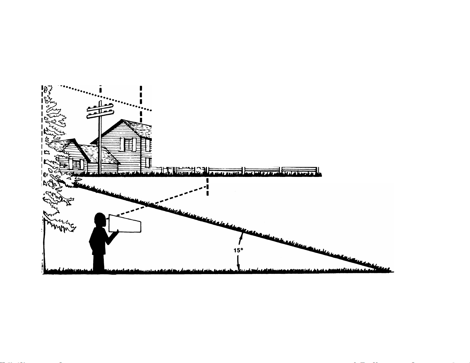
USE THIS SHEET AS A GUIDE TO DETERMINE SLOPES WHERE YOU MAY NOT OPERATE SAFELY.
SIGHT AND HOLD THIS LEVEL WITH A VERTICAL TREE
----------------
^
--------------------------------
ffUMITHT^tr fT n rr
03
A POWER POLE
A CORNER OF A BUILDING
I
........
...
.....
OR A FENCE POST
„
...................
.
............................................................ S
(D
O
“O
CO
(0
■o
(D
(D
5’
0)
(0
0)
CD
CO
n
o
CD
c
n
c
CD
-T
CD
-4»
CD
CD
3
o
CD
M WARNING ^
Do not mow on inclines with a slope in excess of 15 degrees (a rise of approximately 2-1/2 feet every 10 feet). A
riding mower could overturn and cause serious injury. If operating a walk-behind mower on such a siope, it is
extremely difficult to maintain your footing and you could slip, resulting in serious injury.
Operate RIDING mowers up and down slopes, never across the face of slopes.
Operate WALK-BEHIND mowers across the face of slopes, never up and down slopes.
Page 4
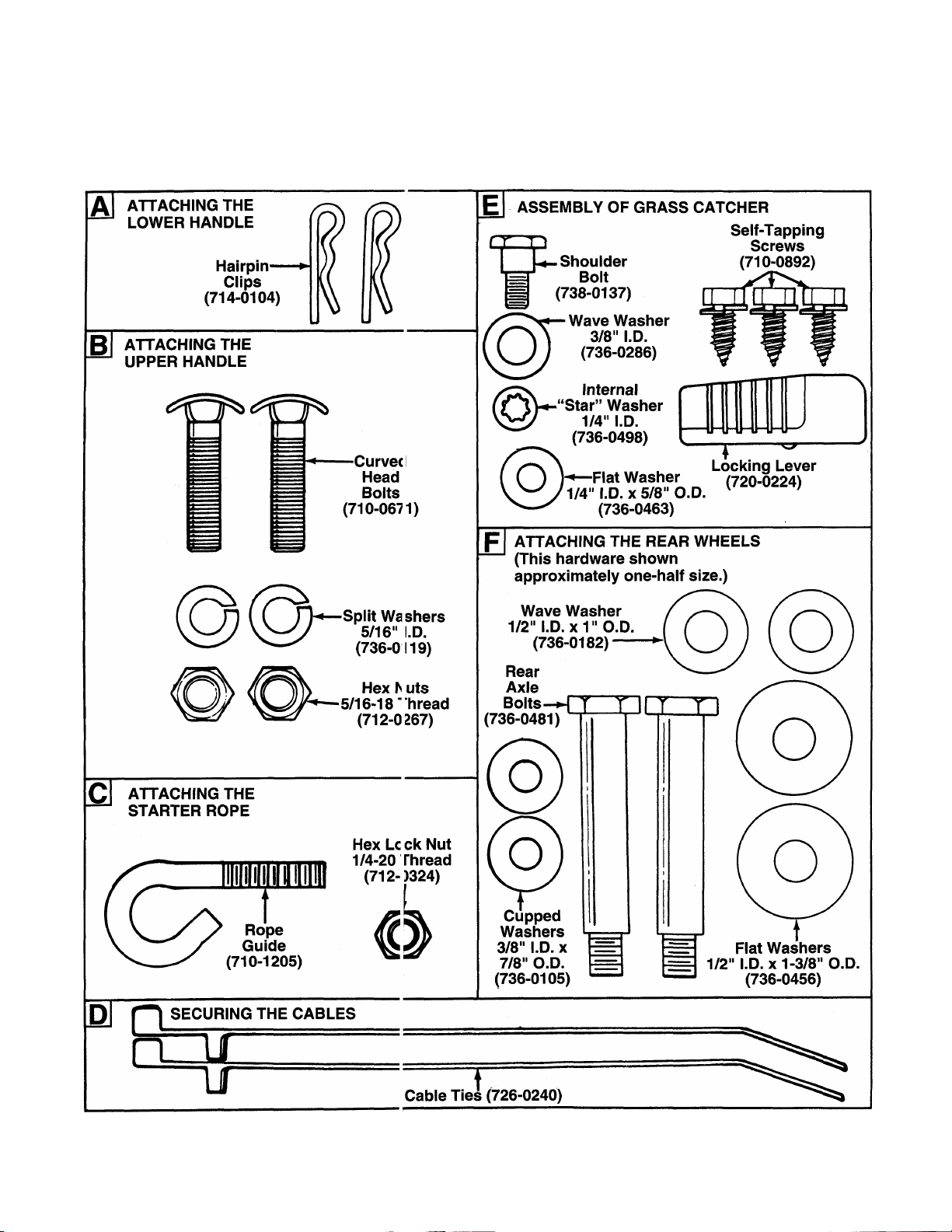
CONTENTS OF HARDWARE PACK
Remove this sheet from your owner’s manual and lay the hardware on the illustration for identification purposes.
After assembly, keep the Slope Gauge which i > on the reverse side of this sheet for future use.
(Hardware pack may contain extra items which are not used on your unit. Part numbers are shown in
parentheses.)
o
c
>
o.
(0
0
INCHES
I
I I I
I I I I I
1
I I I I I I II I I
2
Page 5
ASSEMBLY INSTRUCTIONS
^ IMPORTANT; This unit is shipped WITHOUT
GASOLINE or OIL. After assembly, service engine
with gasoiine and oii as instructed in the separate
engine manuai packed with your unit.
NOTE: Reference to right or left hand side of the
mower is observed from the operating position.
Tools Required for Assembly
(1) Pair of Pliers
(1) 1/2" Wrench*
(1) Adjustable Wrench*
(1) Phillips Screwdriver
UNPACKING
1. Remove the lawn mower from the carton by
opening the top flaps and lifting the unit out. Be
careful of the staples. Make certain all parts and
literature have been removed from the carton
before the carton is discarded.
2. Disconnect the spark plug wire and move away
from the spark plug.
3. Stretch out the control cables (with control box
attached) to the left side of the mower and place
on the floor. Be careful not to bend or kink the
cables at any time during assembly.
4. Remove page four from this manual and lay the
contents of the hardware pack on the illustration
for identification.
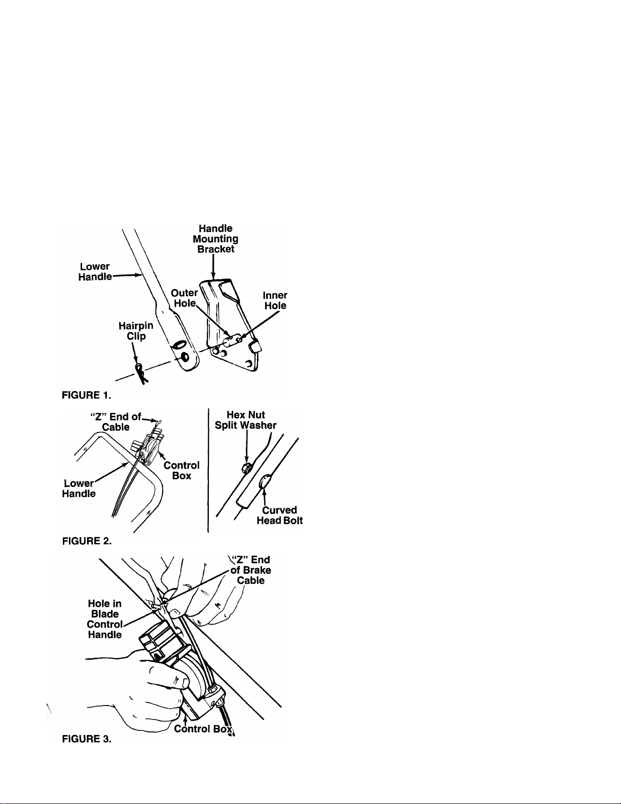
ATTACHING THE LOWER HANDLE (Hardware A)
1. Attach the lower handle by placing the bottom
holes in the lower handle over the weld pins on
the handle mounting brackets on the rear of the
deck. The extra hole in the upper part of lower
handle must be on the right side of the unit.
2. Using a pair of pliers, squeeze one leg of the
lower handle against the handle mounting brack
et. Insert the hairpin clip into the inner hole on the
-------
weld pin. See figure 1. Repeat on other side.
NOTE: There are two (2) holes in the handle mount
ing brackets. Place the hairpin clip in the inner hole
for operation. Outer hole is for storage.
ATTACHING THE UPPER HANDLE (Hardware B)
1. Slide the control box over the lower handle so
that the cable with the “Z” end is routed above the
lower handle, and the other cable is routed below.
-------
See figure 2.
2. Place the upper handle in position over the lower
handle. The hole in the side of the blade control
handle (attached to the upper handle) must be on
the left side. Make certain the blade control han
dle is on top of the upper handle.
3. Secure the upper handle using the curved head
bolts, split washers and hex nuts as shown in fig
ure 2. Tighten securely.
-ATTACHING THE CDNTRDL BDX
Attach the control box to the upper handle as follows.
1. Remove the truss machine screw and hex lock
nut from the middle of the control box using a
Phillips screwdriver. (Hold your finger over the
hex lock nut so it stays inside the control box so
you can unscrew the truss machine screw.)
2. Holding the control box near the left side of the
upper handle (control box must be inside the han
dle), hook the “Z” end of the brake cable into the
control handle from the outside to the inside. See
figure 3.
Page 6

FIGURE 4.
Truss
MacP ine
Sen iw
3. Place the control box on the upper handle just
below the end of the control handle as shown in
— figure 4. Secure with hardware removed in step
one by placing hex lock nut into the indent on the
inside of the control box. Screw the truss machine
screw into the hex lock nut.
SECURING THE CABLES (Hardware D)
Secure all cables to the left side of the handle as fol
lows.
WARNING: When attaching the control
cables, the cables must be routed to
A
1,
— inside or outside of the handles. See figure 5A.
2. Secure the cables with the cable ties. See figure
avoid contact with all sharp edges and
hot surfaces to prevent damage to the
cables, which will render the controls
inoperative.
Insert posts on cable ties into holes provided on
the lower handle. The holes may be either on the
5B. Trim excess ends of cable ties.
FIGURE 6.
Rear
Wheel
Cupped
Washer
FIGURE 7.
Rope Guide
Starter
Rope
Rear He ile
In Five it
Bar
ATTACHING THE STARTER ROPE (Hardware C)
1. The starter rope is inside the top of the engine.
Additional rope may be wound around the starter
handle. If so, unwind the rope from the handle.
2. With the spark plug wire disconnected and
grounded, depress the blade control handle and
pull the rope out of the engine.
-3. Place the rope guide around the starter rope, so
the rope guide is positioned as shown (bends
downward slightly). Insert the rope guide through
the right side of the lower handle, and secure with
hex lock nut. See figure 6.
ATTACHING THE REAR WHEELS (Hardware F)
-Assemble the rear wheels as follows. See figure 7.
1. Move the wheel height adjusters so the deck is in
the lowest cutting position.
2. Lift the rear of the unit up and block securely.
3. Place one large flat washer on axle bolt, then the
wave washer (cupped side against the flat wash
er as shown in figure 7, inset).
4. Insert axle bolt through one rear wheel. Place
cupped washer on axle bolt (crowned side of
washer goes against the wheel).
5. Thread axle bolt into rear hole of pivot bar.
Tighten securely.
6. Assemble other rear wheel in the same manner.
Page 7

INSTALLATION OF HUB CAPS (Optional)
1. If your mower is equipped with hub caps which
have four tabs, line up the tabs on the hub caps
with the holes in the wheels. Push to lock in posi
tion.
2. If your mower is equipped with 2“ wide tires,
place hub caps in position against the inner hub
of the wheel. Press firmly around the center por
tion of hub cap in a circular motion, similar to
installing a lid on a round, plastic container. See
------
figure 8. The hub caps are flexible and will snap
over the 3-1/2" diameter wheel hubs.
FIGURE 8.—Optional Hub Caps
NOTE: It may be helpful to place the hub caps in hot
tap water for several minutes to make them pliable
before installing, especially if the temperature is less
than 60P F.
3. For other types of hub caps, simply press into
place on wheel hub.
FINAL ASSEMBLY OF MOWER
Make certain all nuts and bolts are tightened securely.
ASSEMBLY OF GRASS CATCHER (Hardware E)
NOTE: Make certain the grass bag is turned right side
out before assembling (warning label will be on the
outside).
1. There are three holes in the rear frame. With the
-------
holes on the upper side as shown in figure 9A,
insert one end of the rear frame into the cloth
channel on the edge of the grass catcher bag.
Feed all the material on one side of the frame,
then work it around the frame. See figure 9B.
FIGURE 9.
2. Slide the ends of the front frame assembly into
the ends of the rear frame as shown in figure
— 10A.
Secure front of bag to front frame by slipping
plastic channels on sides and bottom of bag over
frame. See figure 10B.
Page 8

4. Attach the hardtop cover to the grass catcher as
— follows. See figure 11.
a. Place the cover in position on top of the grass
catcher. Press the rear frame into the channel
on the rear of the cover (beneath the rear han
dle).
b. Slide the notches on the sides of the cover
over the front catcher frame.
c. Attach rear of cover to frame using the flat
washer and one self-tapping screw as shown
in figure 11. Attach the sides of the cover to
frame with the other two self-tapping screws.
5. Assemble the locking lever as follows:
a. Place wave washer on shoulder bolt (crowned
side of washer goes against the head of bolt).
b. Insert shoulder bolt up through hole in hardtop
--------
cover as shown in figure 12. Place “star”
washer over shoulder bolt.
c. Thread shoulder bolt into the grass catcher
locking lever, using a 9/16" socket wrench. Do
not overtighten. Locking lever must be able to
pivot.
FIGURE 13.
Rear
Deflector
ATTACHING BAG TO MOWER
Lift the rear deflector on the mower. Place the loops
on the grass catcher frame over the pins on the back
-of the mower. See figure 13. Release the rear deflec
tor. Turn the locking lever to the locked position to
secure the rear deflector. See figure 13, inset.
To remove the grass catcher, turn the locking lever to
the unlocked position and lift the rear deflector on the
mower. Lift the grass catcher up, over the pins on the
back of the mower. Release the deflector.
Page 9

FIGURE 14.
CONTROLS
handle must be depressed in order to operate the
unit. Release the blade control handle to stop the
engine and blade.
A
THROTTLE CONTROL
The throttle control is located on the side of the upper
handle. It is used to regulate the engine speed.
WARNING: The blade will be rotating whenever the engine is running.
BLADE CONTROL HANDLE
WARNING: This control mechanism is a
safety device. Never attempt to bypass
A
The blade control handle is located on the upper han
dle of the mower. See figure 14. The blade control
its operations.
OPERATION
TO REDUCE THE RISK OF INJURY. 00 NOT
OPERATE MOWER UNLESS REAR TRAILING
SHIELD AND THIS GUARD OR ENTIRE
GRASS CATCHER IS IN ITS PROPER PLACE.
WARNING: The throttle control cannot be
A
RECOIL STARTER
The recoil starter handle is attached to the handle.
See figure 14. Stand behind the unit in the operating
position to start the unit.
NOTE: For shipping purposes your mower is set with
the wheels in a low cutting height position. For best
results raise the cutting position until it is determined
which height is best for your lawn. See cutting height
adjustment section.
GAS AND OIL FILL-UP
Service the engine with gasoline and oil as
instructed in the separate engine manual packed with
your mower. Read instructions carefully.
A
used to stop the engine.
WARNING: Never fill fuel tank indoors,
with engine running or until the engine
has been allowed to cool for at least two
minutes after running.
FIGURE 15.
Keep hands and feet away from the chute area on
cutting deck. See figure 15.
The operation of any lawn mower can result in for
eign objects being thrown into the eyes, which
can result in severe eye damage.
Always wear safety glasses or eye
shields. We recommend wide vision
safety mask for over spectacles or
standard safety glasses.
TO START ENGINE AND ENGAGE BLADE
1. Attach spark plug wire to spark plug. If unit is
equipped with a rubber boot over the end of the
spark plug wire, make certain the metal loop on
the end of the spark plug wire (inside the rubber
boot) is fastened securely over the metal tip on
the spark plug. See figure 16.
Metai Loop
on Spark
Plug Wire
Rubber Boot
FIGURE 16.
Page 10

2. Move throttle control lever all the way forward.
3. If engine is equipped with a primer, prime engine
as instructed in the separate engine manual
packed with your unit.
4. Standing behind the unit, depress the bla ie con
trol handle and hold it against the upper handle
as shown. See figure 17.
5. Grasp the recoil starter handle and pLil back
rapidly, extending rope fully. Return it sbwiy to
the rope guide.
6. After engine starts, move throttle control to
desired engine speed.
NOTE: If any problems are encountered, refer to the
Trouble Shooting Guide on page 16.
For the best results, do not cut wet grass because it
tends to stick to the underside of the mower, prevent
ing proper discharge of grass clippings, and could
cause you to slip and fall. New grass, thick grass or
wet grass may require a narrower cut. Blade speed
should be adjusted to the condition of the lawn.
For best results, cut off one-third or less of the total
length of the grass. Lawn should be cut in the fall as
long as there is growth.
This mower is designed to be operated at full throttle
to give you the best cut and do the most effective job
of bagging the cut grass.
WARNING: If you strike a foreign object,
A
stop the engine. Remove wire from spark
plug, thoroughly inspect the mower for
any damage, and repair the damage
before restarting and operating the
mower. Extensive vibration of the mower
during operation is an indication of dam
age. The unit should be promptly
inspected and repaired.
FIGURE 17.
TO STOP ENGINE AND BLADE
1. Move throttle control lever to SLOW positi(>n.
2. Release the blade control handle to slop the
engine and blade.
WARNING: The blade continues to rotate
for a few seconds after the engine is shut
A
3. Disconnect the spark plug wire and giound it
USING YOUR ROTARY MOWER
A
Be sure that lawn is clear of stones, sticks, wire, or
other objects which could damage lawn mDwer or
engine. Such objects could be accidently th own by
the mower in any direction and cause serious person
al injury to the operator and others.
off.
against the engine to prevent accidental starting
while equipment is unattended.
WARNING: Never operate your unit with
out either the rear defiector oi entire
grass catcher assembly in piace.
ADJUSTMENTS
WARNING: Do not at any time make any
adjustment to lawn mower without first
A
CUTTING HEIGHT ADJUSTMENT
An adjusting plate and thumb lever at each wheel
position provides cutting height adjustment. Each
adjusting plate has nine height positions. Height of cut
will be changed when the thumb lever is moved from
one hole to another. Simply depress the lever towards
wheel and move wheel and lever assembly to desired
position. All wheels must be placed in the same rela
tive position. See figure 18.
stopping engine and disconnecting spark
plug wire.
10
Page 11

THROTTLE CONTROL ADJUSTMENT
If the throttle control requires adjustment or if it has
been replaced, adjust as follows.
1. Remove the screw shown in figure 19. Remove
the cable clamp from the cable.
NOTE: If you have a Tecumseh engine, simply loosen
the screw shown in figure 19B so the cable will move
freely beneath the clamp. It is not necessary to
remove the screw and clamp completely.
2. Push the throttle control lever on the handle all
the way forward as far as it will go, then back it off
one “click”. Make certain the throttle control
lever remains in this position.
3. Push the control lever on the engine as far toward
the rear of the engine as it will go. Secure the
cable in this position with the cable clamp and
screw.
Minor carburetor adjustments may be required to
compensate for differences in fuel, temperature, alti
tude and load. To adjust carburetor, refer to the sepa
rate engine manual packed with your mower.
NOTE: A dirty air cleaner will cause an engine to run
rough. Be certain air cleaner is clean and attached to
the carburetor before adjusting carburetor. Refer to
the separate engine manual.
LUBRICATION
WARNING: Always stop engine and dis
connect spark plug wire before cleaning,
A
Blade Control—Lubricate the pivot points on the
blade control handle and the brake cable at least
once a season with light oil. See figure 20. The blade
control must operate freely in both directions.
lubricating or doing any kind of work on
lawn mower.
Pivot
Point
Brake
Cable
FIGURE 19A.—Briggs & Stratton
Quantum Engines
Cable
Control
Lever
On Engine
FIGURE 19B.—Tecumseh Engines
CARBURETOR ADJUSTMENTS
WARNING: If any adjustments are made
to the engine while the engine is running
A
(e.g. carburetor), keep clear of all moving
parts. Be careful of heated surfaces and
muffler.
Screw
FIGURE 20.
Discharge Chute Deflector—The torsion spring and
pivot point should be lubricated periodically with light
oil to prevent any rust or binding. Deflector must work
freely.
Wheels—Mower rhay be provided with ball bearing
wheels. Lubricate at least once a season with light oil.
Also, if the wheels are removed for any reason, lubri
cate the surface of the axle bolt and the inner surface
of the wheel with light oil. A 4 oz. plastic bottle of light
oil lubricant is available. Order part number 737-0170.
Engine oil may also be used.
Engine—Follow engine manual for lubrication instruc
tions.
MAINTENANCE
WARNING: Be sure to disconnect and
ground the spark plug wire before per
A
NOTE: When tipping the unit, empty the fuel tank and
keep engine spark plug or muffler side up.
forming any repairs or maintenance.
11
Page 12

TROUBLE SHOOTING
Refer to page 16 of this manual for trouble shooting
information.
CUTTING BLADE
When removing the cutting blade for sharpening or
replacement, protect hands by using heavy gbves or
a rag to grasp the cutting blade. Remove the holt and
bell washer which hold the blade and adapter to the
engine crankshaft. Remove the blade and adapter
from the crankshaft.
If the blade or blade adapter needs replacing, remove
the two small bolts, lock washers and nuts wh ch hold
the blade to the adapter.
WARNING: Periodically inspect tha biade
adapter for cracks, especialiy if you
A
strike a foreign object. Repiacc when
necessary.
When sharpening the blade, follow the original angle
of grind as a guide. It is extremely important that each
cutting edge receives an equal amount of grinding to
prevent an unbalanced blade. An unbalanced blade
will cause excessive vibration when rotating at high
speeds, may cause damage to the mower and could
break, causing personal injury.
It is recommended that the blade always be removed
from the adapter for the best test of balance.
The blade can be tested by balancing it on round
shaft screwdriver. Remove metal from the heiivy side
until it balances evenly.
Before reassembling the blade and the blade adapter
to the unit, lubricate the engine crankshaft and the
inner surface of the blade adapter with light oil.
Lubricating the bolt holes, bolts and inner sulace of
the nuts with light oil is also recommended. A 4 oz.
plastic bottle of light oil lubricant is available. Order
part number 737-0170. Engine oil may also be used.
When replacing the blade, be sure to install the blade
with the side of the blade marked “Bottom” (or with
part number) facing the ground when the mo\/er is in
the operating position.
Blade Mounting Torque
Center Bolt: 450 in. lbs. min., 600 in. lbs. max.
Blade Adapter Bolts: 200 in. lbs. min., 350 in. It is. max.
To insure safe operation of your unit, all nuts and bolts
must be checked periodically for correct tightne ss.
DECK
The underside of the mower deck should be cleaned
after each use to prevent a buildup of grass clippings,
leaves, dirt or other matter. If this debris is al owed to
accumulate, it will invite rust and corrosion, and may
cause an uneven discharge of grass clippinc s at the
next cutting.
The deck may be cleaned by tilting the mower and
scraping clean with a suitable tool (make certain the
spark plug wire is disconnected).
ENGINE
Refer to the separate engine manual for engine
maintenance instructions.
Maintain engine oil as instructed in the separate
engine manual packed with your unit. Read and follow
instructions carefully.
Service air cleaner every 25 hours under normal con
ditions. Clean every few hours under extremely dusty
conditions. Poor engine performance and flooding
usually indicates that the air cleaner should be ser
viced. To service the air cleaner, refer to the separate
engine manual packed with your unit.
The spark plug should be cleaned and the gap reset
once a season. Spark plug replacement is recom
mended at the start of each mowing season; check
engine manual for correct plug type and gap specifi
cations.
Clean the engine regularly with a cloth or brush.
Keep the cooling system (blower housing area) clean
to permit proper air circulation which is essential to
engine performance and life. Be certain to remove all
grass, dirt and combustible debris from muffler area.
OFF-SEASON STORAGE"
The following steps should be taken to prepare lawn
mower for storage.
1. Clean and lubricate mower thoroughly as
described in the lubrication instructions.
2. Refer to engine manual for correct engine storage
instructions.
3. Coat mower’s cutting blade with chassis grease
to prevent rusting.
4. Store mower in a dry, clean area. Do not store
next to corrosive materials, such as fertilizer.
NOTE: When storing any type of power equipment in
an unventiiated or metal storage shed, care should be
taken to rust-proof the equipment. Using a light oil or
silicone, coat the equipment, especially cables and all
moving parts.
HANDLE STORAGE
The handle may be placed in an upright position for
storage. Move hairpin clips to outer hole on weld pins.
See figure 1. Press outward on the bottom of the
lower handle and push forward. The handle will lock
in this position.
To place the handle in the operating position, remove
the starter rope from the rope guide. Grasp the lower
handle at the bottom, press outward slightly and tip
the handle backward. Place the hairpin clips in the
inner holes. With the spark plug wire disconnected
and grounded, depress the blade control handle and
pull the starter rope out from the engine. Slip the
starter rope into the rope guide.
12
Page 13

*For faster service obtain standard nuts, boits and washers iocaliy.
if these items cannot be obtained iocaiiy, order by part number
and size as shown on parts list.
CODE: N notates a new part (not previously existing). A three digit
number is the color code. Specify color code as shown below if
color or finish is important when ordering parts, [i.e., 638 for Red
Finish].
NOTE: The engine is not under warranty by the
mower manufacturer. . .If repairs or service is
needed on the engine, please contact your
nearest authorized engine
service outlet. Check the
“Yellow Pages” of your
telephone book under
“Engines-Gasoline.”
Wheel w/o Bearings Wheels With Bearings
Tread***
Diamond 734-1698 (7")
Waffle 734-1162A (8") 738-0102 “T” T read
“S”Wave
Rib 734-1169 (8")
Bar 734-1609 (7")
Ass’y- Comp.
734-1697 (8")
734-1512A (8") 738-0102
634-0020
(8" X 1.75")
734-1608
(8" X 2")
Axle Bolt Tread***
738-0102
738-0102
738-0144
738-0102
738-0102
738-0102
Find It Fast
in The
Yellow Pages
Ass’y. Comp. Bearings
“S” Wave
Waffle 734-0645
734-1513B
(Gray)
734-1517B
(Beige)
734-1259
734-1260
“FRONT WHEEL CHART
Ball Brg. 1/2" I.D.-741-0180 (2 per Wheel)
Ball Brg. 1/2" I.D.-741-0180 (2 per Wheel)
Ball Brgs. 3/8" I.D.-741-0267, 1/2" I.D.-741-0484, Spacer 750-0434
Ball Brg. 1/2" I.D.-741-0180 (2 per Wheel)
Ball Brgs. 3/8" I.D.-741-0267, 1/2" I.D.-741-0484, Spacer-750-0434
456—Radiant Tangerine
460—Green Flake
483—Charcoal Gray 640—Green
498—Yellow
499—Beige
629—Silver Flake
Color Codes
637—Black
638—Red
646—CM Blue
657—Teal
Axle Bolt
738-0102
738-0102
710-1020
738-0102
710-1020
*Tread Type: Waffle
; Rib
; Bar
; “T” Tread ; “S” Wave ; Diamond
13
Page 14

Models 515R, 516R and 518R
OPTIONAL HUB CAPS
Description Part No.
Gray (5-1/2" Dia.)
Beige (5-1/2" Dia.)
Gray (3-1/2" Dia.)
Black (1-1/2" Dia.)
Red (1-3/8" Dia.)
Black (1-3/8" Dia.)
731-0981A
731-0982A
720-0249
720-0251
731-0342
731-0268
This instruction manuai covers vari
ous models, and aii specifications
shown do not necessarily apply to
your model. Specifications subject to
change without notice or obligation.
14
1»
^74
* 74
Page 15

Models 515R, 516R and 518R
PARTS LIST FOR MODELS 515R, 516R AND 518R ROTARY MOWERS
^EF.
NO.
13
14 736-0119
15
16
17 726-0240
18
19 749-0504C
22 735-0639
23 811-00185
24 746-0876
25
26
27
^28
29
30 734-1653
31 710-1055
32 736-0169 L-Wash. 3/8" I.D.
33
34 731-0858 Seal—Extrusion
35
36 726-0106 Cap Speed Nut
37 747-0698B Hinge Pin 17.75" Lg. 87 732-0417A
38
39
40 711-0805
41 736-0169 L-Wash. 3/8" I.D.*
42 712-0711 Hex Jam Nut 3/8-24 Thd.
43
44 12297A Handle Brkt. Ass’y.—L.H.
45
46
47
48
49
PART
NO.
1 747-0824 N
647-0004 N Control Handle Ass’y. (Deluxe)
2
720-0226
710-0605
3
4
736-0501
5 712-0291
6 746-0843
746-0845
7 712-0324 Hex L-Nut 1/4-20 Thd.
8 749-0438B
710-1205 Rope Guide 59
712-0267 Hex Nut 5/16-18 Thd.*
746-0554 Control Cable—40.5" (B&S) 62
746-0555
710-0671
CODE
Control Handle Ass’y- (Std.)
Foam Grip (Optional) 52 710-0654A
N Oval C-Sunk Scr.
Spr. Wash. .66" I.D.
N
Hex L-Nut 1/4-20 Thd.
N
Throttle Cable—55" (B&S) 55 17003
N Throttle Cable—45" (Tec.)
Upper Handle
L-Wash. 5/16" I.D.* 60
Control Cable—55" (Tec.)
Cable Tie
Curved Carriage Bolt 5/16-18
Lower Handle
Spark Plug Boot (Optional)
N Throttle Box Comp. (Incl. Ref. 3, 74 753-0485
DESCRIPTION
X 1.38" Lg. 72 736-0453
4, 5, 24, 25)
N Throttle Lever
746-0875 N Throttle Body
751-0568 N Cable Clamp (B&S)
—
710-1237 N
734-1661
712-0241
714-0104 Int. Cotter Pin 5/16" Dia.
750-0566
732-0577A Torsion Spring—L.H.
732-0578A Torsion Spring—R.H.
710-1017 Torx Mach. AB-Tap Scr. 1/4 x
731-0970B
731-0931
12296A Handle Brkt. Ass’y.—R.H.
710-0892
Engine
Hex Self-Tap Scr. #10-32 x .62"
Lg. (B&S) 79
Wheel Ass’y. Comp.—Steel Rim
Wheel Ass’y. Comp.—Plastic 82
Rim
Hex Bolt 3/8-24 X 1"
Hex Nut 3/8-24 Thd.
Spacer .255" I.D.
Shid. Pin 3/8-24 x 1.43" Lg.
.62" Lg.
Deflector Plug
Corner Plug
Hex L-Wash. AB-Tap Scr.
1/4 X .62" Lg.
REF.
NO.
50 736-0356
51 712-0798
53
54
56 731-0669
57
58
61
63
64
65 736-0463
73
75
76
77
78
80
83
84
85 17488 Pivot Bar—R.H.
86
88
89
90
92
93 736-0498
94
95
96
99 736-0456
100
PART
NO.
16998A
17014
731-0859
731-0856A
731-0857A
749-0736A
764-0411
764-0252
741-0484
738-0481
736-0452
742-0306A
753-0484
710-0757
710-1044
15261A
15262B Pivot Bar
14832
738-0507B
736-0105
14578
14579
**
14764C Index Plate
17489
720-0190
17490
17491
736-0232
720-0224
736-0286
738-0137
731-0564
736-0182
CODE
Bell-Wash. .39" I.D.
Hex Nut 3/8-16 Thd.*
Hex L-Wash. Hd. Scr.
638/N 21" Deck Ass’y.
Chute Baffle
Retaining Strip 14.25" Lg.
Rear Flap 17.30" Lg.
Rear Chute Deflector
Hardtop Handle
Hardtop Bag Cover
Rear Catcher Frame
Front Catcher Frame
Grass Bag
Bearing (2 Per Wheel)
ShId. Bolt .5 Dia. x 2.62"
FI-Wash. .281" I.D.
Bell-Wash. .46" I.D. (Splined)
Bell-Wash. .39" I.D. (Keyed)
21" Blade
Blade Adapter Kit (Splined)
Blade Adapter Kit (Keyed)
Hex Bolt 7/16-20 X 1.5" Lg.
Hex Bolt 3/8-24 x 1.5" (Keyed)
Height Adj. Plate
Spring Lever Ass’y. w/Knob
Shid. Bolt .50" Dia. x .357"
Bell-Wash. .38" I.D. x .88" O.D.
Height Adj. Ass’y. Comp.—R.H.
Height Adj. Ass’y.
Front Wheel Ass’y. Comp.
Pivot Bar—L.H. (Not Shown)
Spring Lever Knob
Spring Lever
Rear Height Adj. Ass’y.
Rear Height Adj. Ass’y.
Front Axle Bolt
Wave Wash. .53" I.D. x .78"
Grass Catcher Locking Knob
Internal L-Wash. 1/4" I.D.
Wave Washer 3/8" I.D.
Shid. Bolt .342" Dia. x .268"
Plug
FI-Wash. .51" I.D. X 1.373"
Spr. Wash. .5" I.D. x1" O.D.
DESCRIPTION
3/8-16 X 1" Lg.
Comp.—L.H. (Not Shown)
Comp.—R.H.
Comp.—L.H. (Not Shown)
O.D. (Used w/Ball Brg.)
15
Page 16

TROUBLE SHOOTING GUIDE
Trouble Possible Cause(i )
Engine fails to start
Engine runs erratic
Engine overheats
Occasional skip
(hesitates) at high speed
1. Blade control h andle disengaged.
2. Spark plug wire disconnected.
3. Throttle control lever not in CHOKE
or START posi ion.
4. Fuel tank empt /, or stale fuel.
5. Blocked fuel lire.
6. Faulty spark pi jg.
7. Engine floodec.
1. Unit running in START position
2. Spark plug wins loose.
3. Blocked fuel lir e or stale fuel.
4. Vent in gas cap plugged.
5. Water or dirt in fuel system.
6. Dirty air cleane r.
7. Carburetor out of adjustment.
1. Engine oil leve low.
2. Air flow restrict sd.
3. Carburetor not adjusted properly.
1. Spark plug gaf too close.
2. Carburetor idle mixture adjustment
improperly set.
Corrective Action
1. Engage blade control handle.
2. Connect wire to spark plug.
3. Move throttle lever to CHOKE or
START position.
4. Fill tank with clean, fresh gasoline.
5. Clean fuel line.
6. Clean, adjust gap or replace.
7. Remove spark plug, dry the plug, and
crank engine with plug removed and
throttle in off position. Replace spark
plug, connect wire and resume starting
procedures.
1. Move throttle lever to FAST position
2. Connect and tighten spark plug wire.
3. Clean fuel line; fill tank with clean,
fresh gasoline.
4. Clear vent.
5. Drain fuel tank. Refill with fresh fuel.
6. Clean air cleaner.f
7. Adjust carburetor.t
1. Fill crankcase with proper oil.
2. Remove blower housing and clean.t
3. Adjust carburetor.t
1. Adjust gap to .030”.
2. Adjust carburetor.t
Idles poorly
Excessive vibration
Mower will not
discharge grass
Uneven cut
fRefer to separate engine manual packed with yoi r unit.
Note: For repairs beyond the minor adjustments listed above, contact your local authorized service dealer.
1. Spark plug fou ed, faulty or gap too wide.
2. Carburetor improperly adjusted.
3. Dirty air cleane r.
1. Cutting blade I oose or unbalanced.
2. Bent cutting bl ide.
1. Engine speed :oo low.
2. Wet grass.
3. Excessively hi jh grass.
1. Wheels not pc sitioned correctly.
2. Dull blade.
1. Reset gap to .030” or replace spark plug.
2. Adjust carburetor.t
3. Clean air cleaner.f
1. Tighten blade and adapter.
Balance blade.
2. Replace blade.
1. Set throttle between 3/4 and full throttle.
2. Do not mow when grass is wet; wait until
later to cut.
3. Mow once at a high cutting height, then
mow again at desired height or make a
narrower cutting swath (1/2 width).
1. Place all four wheels in same
height position.
2. Sharpen or replace blade.
FOR REPLACEMENT PARTS, CONTACT:
SERVICE DEPARTMENT • P.O. BOX 360900 • CLEVELAND, OHIO 44136
 Loading...