

Page 1

10*
Model Nos.
ROTARY MOWER
112-260
I iiPORTA N T
SAFE OPERATION PRACTICES - WALK BEHIND MOWERS
TRAINING
1. Read the Operating and Service Instruction Manual
carefully. Be thoroughly familiar with the controls and
proper use of the equipment.
2. Never allow children to operate a power mower.
3. Keep the area of operation clear of all persons,
particularly small children, and pets.
PREPARATION
1. Thoroughly inspect the area where the equipment is to
be used and remove all stones, sticks, wire, bones and
other foreign objects.
2. Do not operate equipment when barefoot or wearing
open sandals. Always wear substantial footwear.
3. Check fuel before starting engine. Do not fill gasoline
tank indoors, when engine is running, or while engine
is still hot. Wipe off any spilled gasoline before starting
engine.
4. Disengage self-propelled mechanism or drive clutch on
units so equipped before starting engine (motor).
5. Never attempt to make a wheel height adjustment while
engine (motor) is running.
6. Mow only in daylight or in good artificial light.
7. Never operate equipment in wet grass. Always be sure
of your footing; keep a firm hold on the handle and
walk; never run.
OPERATION
1. Do not change engine governor settings or overspeed
engine.
2. Do not put hands or feet near or under rotating parts.
Keep clear of discharge opening at all times.
3. Stop blade(s) when crossing gravel drive, walks or roads.
4. After striking a foreign object, stop the engine (motor),
remove wire from spark plug, thoroughly inspect the
mower for any damage, and repair the damage before
restarting and operating the mower.
5. If the equipment should start to vibrate abnormally,
stop the engine (motor) and check immediately for the
cause. Vibration is generally a warning of trouble.
6. Stop engine (motor) whenever you leave the equipment,
before cleaning mower housing, and when making any
repairs or inspections.
7. When cleaning, repairing or inspecting, make certain
blade and all moving parts have stopped. Disconnect
spark plug wire and keep wire away from plug to prevent
accidental starting.
8. Do not run engine (motor) indoors.
9. Shut engine (motor) off and wait until blade comes to a
complete stop before removing grass catcher and/or
unclogging chute.
10. Mow across the face of slopes, never up-and-down.
Exercise extreme caution when changing direction on
slopes. Do not mow excessively steep slopes.
11. Always disconnect electric mowers (line operated)
before cleaning, repairing, or adjusting.
12. Never operate mower without proper guards, plates or
other safety protective devices in place.
13. Keep washout ports and other mower housing service
openings closed when mowing.
MAINTENANCE AND STORAGE
1. Check blade and engine mounting bolts at frequent
intervals for proper tightness.
2. Keep all nuts, bolts, and screws tight to be sure equip
ment is in safe working condition.
3. Never store equipment with gasoline in the tank inside
of a building where fumes may reach an open flame or
spark. Allow engine to cool before storing in any
enclosure.
4. To reduce fire hazard keep engine free of grass, leaves or
excessive grease.
5. Check grass catcher bags frequently for wear or deterio
ration. Replace with new bags for safety protection.
MTD PRODUCTS INC
5389 WEST 130th STREET
P. 0. BOX 2741 CLEVELAND OHIO 44111
FORM No. 770-3483
Page 2
112-260
4-CYCLE ENGINE
Change oil after first 5 hours of op
eration while engine is warm. There
after change oil every 25 hours of
operation while engine is warm.
Engine may be drained through oil
filler opening. Be sure to replace
drain plug and oil filler cap.
When ordering parts give the following information:
1. Model number
2. Part number
3. Part Name
4. Color of part
When ordering replacement parts, be sure to specify your mower model
number, part number, description of part, and the number of parts re
quired . . . Parts and service should be handled by your nearest author
ized service firm as recommended by your dealer. Request for parts
and service received at the factory will be forwarded to the appro
priate Central Service Distributor in your area for handling. n
Page 3

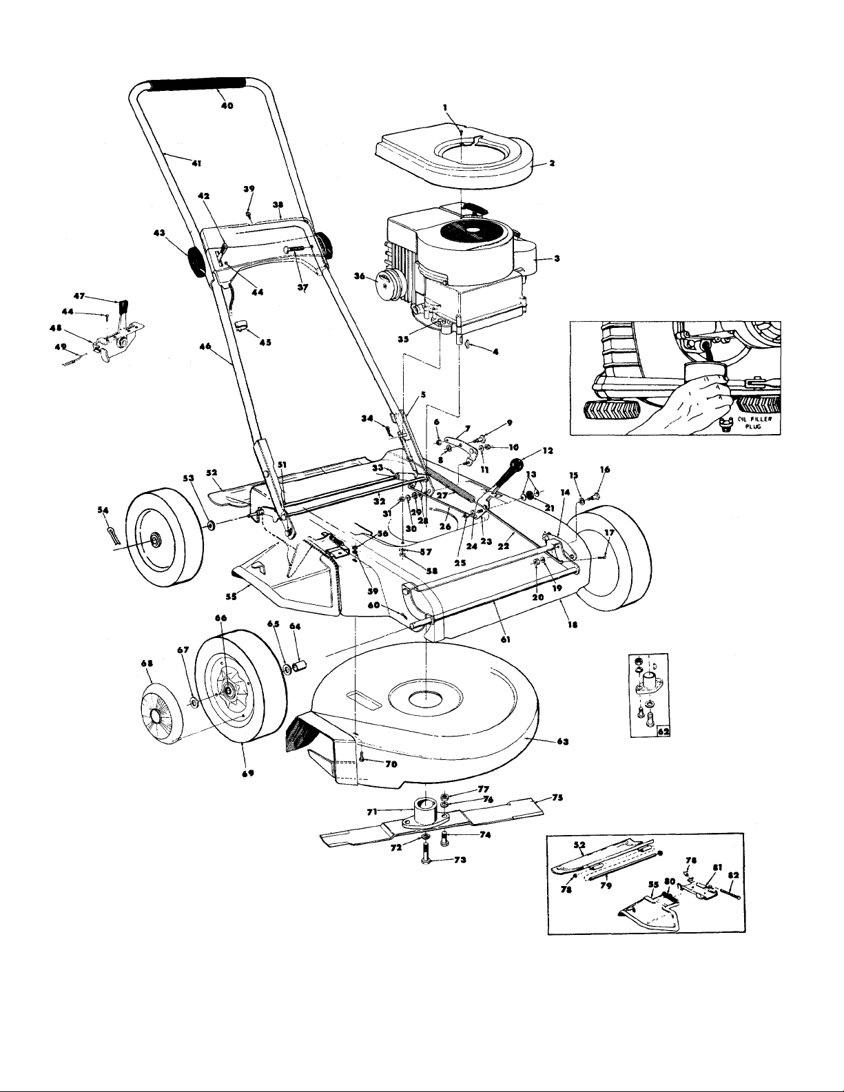
PARTS LIST FOR MODEL No. 112-260
Ref.
No. Part No.
710-407
1
Slotted Hex Washer Hd. Ext. Screw
DESCRIPTION
8-32x1/2” Ig. *
10611
2
—
3
714-365
4
10623
5
712-429
6
10656
7
736-221
8
710-334
9
10 712-429
736-119
11
720-143 Grip — Height Adjuster
12
13 736-105
10658
14
736-221
15
710-334
16
714-507
17
11426
18
736-119
19
712-429 Hex Elastic Stop Nut 5/16—18 Thd.
20
21 736-155
10080
22
23 10666
736-159
24
712-116
25
10080 Rod — Height Adjuster
26
732-153 Spring 8.65 long
27
736-159
28
736-161 Rubber Washer
29
30 736-159
31 712-372
10942
32
33 714-115
34 714-104
710-158 Hex Hd. Cap Sew. 5/15-24 x 1%” Ig.*
35
310-9278
36
37 710-405
11606
38
710-407
39
Engine Shroud
Engine
Key - HiPro 505
Left Hand Pivot Arm Assembly
Hex Elastic Stop Nut 5/16—18 Thd.
Rear Height Pivot Bracket Assy.
Internal Lockwasher
Shoulder Bolt — Special
Hex Elastic Stop Nut 5/16—18 Thd.
Spring Lockwasher 5/16 Screw *
Belleville Washer
Front Height Pivot Bracket Assy.
Internal Lockwasher
Shoulder Bolt — special
Cotter Pin 3/32x3/4” long *
Frame
Spring Lockwasher 5/16 Screw *
Rubber Washer
Rod — Height Adjuster
Height Grip Assembly
Flat Washer
Hex Jam Nut 3/8—24 Thd. NY Lock
Flat Washer
Flat Washer
Hex Center Locknut 5/16—18 Thd *
Rear Axle Assembly
Cotter Pin 1/8” dia. xl” long *
Hairpin Cotter
Exhaust Deflector
Curved Head Sew. 5/16-18x1-3/4” Ig.
Handle Panel
Slotted Hex Washer Head Ext. Sew.
8-32 X Vi” Ig.
40
718-144
41 10011
11611
42
305-9966
43
Grip
Upper Handle
Throttle Control Assembly Complete
Knob — Handle Assembly
Ref.
No. Part No.
DESCRIPTION
44 710-407 Slotted Hex Washer Hd. Ext. Sew.
8—32x1^” long
746-128
45
46
10008
305-7470
47
48
11600
732-144
49
51 736-155
52
11165
53 736-160
Cable Clip
Lower Handle
Throttle Control — Knob
Throttle Control — Bracket Assy.
Conduit and Wire
Rul>ber Washer
Protective Shield
Flat Washer
54 714-115 Cotter Pin 1/8” dia. x 1” long *
55 11141 Chute Deflector
56 712-267 Hex Nut 5/16-18 Thread *
736-119
57
712-123
58
736-119 Spring Lockwasher 5/16 Screw *
59
60
714-115
61 10662
62
10769
63
11425
Spring Lockwasher 5/16 Screw *
Hex Nut 5/16—24 Thread *
Cotter Pin 1/8” dia.x 1” long *
Front Axle Assembly
Bkide Adapter Kit
Lower Deck Assembly
64 748-190 Front Wheel Spacer
736-160
65
Flat Washer
66 741-114 Ba
ADJUSTMENTS
CAUTION: Do not at any time make any adjustment to lawn
mower without first stopping engine and disconnecting spark
plug wire.
1. CUTTING HEIGHT - This mower can be adjusted for
seven cutting heights from l”to 3”. To change the height,
move the height adjustment lever away from the engine
and forward to lower the cutting height and move to rear
to raise the cutting height. The one lever adjusts all four
wheels at the same time.
ASSEMBLY INSTRUCTIONS
NOTE: This instruction manual covers various models, and
all accessories shown do not necessarily apply to
your model mower.
OPERATION
1. Service engine with gas and oil. See engine manual packed
with lawn mower for complete instructions for care and
maintenance of engine. READ DIRECTIONS CAREFULLY.
2. To disconnect the power to the rear drive wheels so the
mower can be pushed by hand, depress the handle. To
engage the drive wheels, lift the handle.
3. When turning the mower depress the handle and raise the
front wheels, and pivot on the tear wheels. The differen
tial action of the rear axle allows the wheels to turn in
dependently on turns and allows both wheels to drive
when the handle is in the UP position.
START ENGINE
With the throttle control lever conveniently mounted on the
handle, start, fast, slow and stopping of the engine is
conveniently controlled with one lever.
After the engine has been properly fueled and oiled (Refer
to engine operating and maintenance instructions), start
engine in the following manner;
RECOIL STARTER
1. Move throttle control lever to START position.
2. Crank engine. Pull recoil until starter drive engages and
then with a quick firm pull. Do not pull out so far that
rope stops with a jerk as this will cause rope failure. Do
not allow rope and handle to snap back into place.
3. After two or three full firm pulls on recoil, move speed
control to run position or as soon as engine fires.
4. Operate a new engine at intermediate speeds and light
load for the first few hours as you would a new automotive
engine.
5. To stop engine, move speed control lever to stop position.
6. If carburetor needs adjustment to start or for operation,
see “Carburetor Readjustment” section.
NOTE; A brief break-in period is essential to insure
maximum engine life. This consists of running the en
gine at half speed for a period of time required to use
one tank of gasoline. This is necessary on the initial
run only. It is also recommended that the oil be changed
after five (5) hours of operation. This allows for the
removal of impurities which may have accumulated dur
ing the break-in period. Subsequent oil changes should
be made as stated in the engine manual. Always check
oil before using your mower. Be sure crankcase is full.
LOW
\ \ 1
r 1 • •
I / /
HIGH
CUTTING HEIGHTS
2. The position of the upper handle can be changed so the
end of the handle turns down instead of up to place it in
the most comfortable position for the operator.
3. THROTTLE - If adjustment becomes necessary, the
throttle control wire assembly can be reset as follows:
a) Loosen, but do not remove, screw securing throttle
control wire assembly at engine.
b) Move throttle control lever on handle to “FAST”
position.
c) Move lever, to which controLwire is fastened at engine,
to full open position and retighten screw to secure
throttle control wire assembly.
LUBRICATION
IMPORTANT: Always stop engine and disconnect spark plug
wire before cleaning, lubricating or doing any kind of work
on lawn mower.
1. ENGINE-Follow engine manual for lubrication instructions.
2. CONTROLS-Lubricate periodically the control assem
blies and conduit and wire with light engine oil for ease
of operation.
3. WHEELS-The front and rear wheels of your unit are ball
bearings and require periodic lubrication with a light
engine oil.
4. PROTECTIVE SHIELD-The pivotpoints on the protective
shield should be lubricated periodically with light oil to
prevent any rust or binding.
5. CHUTE DEFLECTOR-The torsion spring and pivot point
should be lubricated periodically with light oil to prevent
any rust or binding. Deflector must work freely.
CUTTING BLADE
The blade may easily be removed for grinding or replacement
as follows:
1. Remove bolt and lockwasher holding blade and blade
adapter to engine crankshaft.
2. Remove blade and blade adapter from engine crankshaft.
3. Remove two bolts, lockwashers and nuts holding blade
to blade adapter (if necessary).
When sharpening blade, follow the original angle of grind as
guide. It is extremely important that each cutting edge re
ceives an equal amount of grinding to prevent an unbalanced
blade. An unbalanced blade will cause excessive vibration
when rotating at high speeds and may cause damage to the
mower. . . Upon reassembly, make certain all parts are as
sembled properly and tightened securely.
Page 5

GRASS CATCHER Model No. 192-003 is available as optional equip
ment for the mower shown in this manual.
WARNING:
1. The mower should not be operated without the entire grass
catcher or chute deflector in place.
2. The mower should not be operated without the protective shield
on the rear of the deck in place.
NOTE:
Under normal usage bag material is subject to wear, and should be
checked periodically. Be sure any replacement bag complies with the
mower manufacturer's recommendations.
For replacement bags, use only factory authorized replacement bag
No. 764-119.
IMPORTANT
After striking a foreign object, stop the engine (motor), remove wire
from spark plug. Throughly inspect the mower for any damage, and
repair the damage before restarting and operating the mower.
WARRANTY
For one year from date of purchase, MTD Products Inc will replace for the original purchaser,
free of charge, F.O.B. factory or authorized service firm, any part or parts found to be defective in
material or workmanship. All transportation charges on parts submitted for replacement under this
warranty must be paid by the purchaser. This warranty does not include: replacement of parts which
become inoperative through misuse, excessive use, accident, neglect, improper maintenance or al
terations by unauthorized persons. This warranty does not include the engine, motor, battery, bat
tery charger or any component parts thereof. For service on these units, refer to the applicable
manufacturer's warranty.
The above warranty will apply only to the original owner and will be effective only if the war
ranty card has been properly processed. It will not apply where the unit has been used commercially.
Warranty service is available through your local authorized service dealer or distributor. UNDER
NO CIRCUMSTANCES WILL THE RETURN OF A COMPLETE UNIT BE ACCEPTED BY THE
FACTORY UNLESS PRIOR WRITTEN PERMISSION HAS BEEN EXTENDED
Page 6

PARTS INFORMATION
MOWER. TILLER, SNOW THROWER AND TRACTOR
PARTS
Mower, tiller, snow thrower and tractor parts are available
through the authorized service firms listed below. All orders
should specify the model number of your unit, parts
numbers, description of parts and the quantity of each part
required.
A 1 Engine & Mower Co.
327 East 9th Street
Salt Lake City, Utah 84102
American Electric Ignition Co.
124 N. W.8th Street
Oklahoma City, Oklahoma 73102
Auto Electric 8i Carburetor Co.
2625 4th Avenue, S.
P. O. Box 1948
Birmingham, Alabama 35233
Automotive Equipment Service Co.
3117 Holmes Street
Kansas City, Missouri 64109
Bailey's Rebuild Inc.
1325 E. Madison Street
Seattle, Washington 98102
Brown Equipment Distributor Inc.
110 Beech Street
Corydon, Indiana 47112
Bullard Supply
2409 Commerce Street
Houston, Texas 77003
Center Supply Company
6867 New Hampshire Avenue
Takoma Park, Maryland 20012
R. T. Clapp Co.
2016 Magnolia Ave., N. E.
Knoxville, Tennessee 37917
W. B. Clements
400 Salem Avenue
Roanoke, Virginia 24016
Morton B. Collins Co.
300 Birnie Avenue
Springfield, Massachusetts 01107
Dixie Sales Company
P. O. Box 1408
327 Battleground Avenue
Greensboro, North Carolina 27402
East Point Cycle 8i Key Shop
1617 Whiteway
East Point, Georgia 30044
Gamble Distributors
West End Avenue
Carthage, New York 13619
Garden Equipment Co., Inc.
6600 Cherry Avenue
Long Beach, California 90805
Henzier, Inc.
2015 Lemay Ferry Road
St. Louis, Missouri 63125
Frank E. Ives & Son
1101 Lincoln Avenue
Prospect Park, Pennsylvania 19076
J. W. Jewett Co.
981 Folsom Street
San Francisco, California 94107
Kenton Supply
8216 North Denver Avenue
Portland, Oregon 97217
Kimber’s Inc.
615 W. Genesee Street
Syracuse, New York 13204
Marr Brothers
423 E. Jefferson
Dallas, Texas 75203
Mathews Auto Electric Co.
420 East 2nd Street
Tulsa, Oklahoma 74120
McClure Lawn & Garden Supply
1114 Lexington Avenue
Mansfield, Ohio 44907
Memphis Cycle 8i Supply Co.
421 Monroe Avenue
Memphis, Tennessee 38103
ENGINE PARTS AND SERVICE
Engine parts and service should be handled by your nearest
authorized engine service firm. Check the yellow pages of
your telephone directory under the listing Engines —
Gasoline, Briggs and Stratton or Tecumseh Lauson — Power
Products.
Moz-AII of Florida, Inc.
365 Greco Avenue
Coral Gables, Florida 33146
National Central, Div. of
Joe Sterling, Inc.
Drawer "D" 687 Seville Rd.
Wadsworth, Ohio 44281
Power Equipment Distributor
36463So. Gratiot Avenue
Mt. Clemens, Michigan 48043
Parts & Sales Inc.
335 West St. Charles Road
Villa Park, Illinois 60181
Power Lawn & Garden Equip. Co.
2551-2571 J. F. Kennedy Road
Dubuque, Iowa 52001
Raub Supply Company
James & Mulberry Sts.
Lancaster, Pennsylvania 17604
Radco Distributors
2403 Market Street
P.O.Box 3216
Jacksonville, Florida 32206
Richmond Battery 8i ignition
P. O. Box 25369 - 957 Myers St.
Richmond, Virginia 23260
Smith Hardware Company
515 N. George Street
Goldsboro, North Carolina 27530
South Denver Lawn Equip. Co.
527 West Evans
Denver, Colorado 80223
Suhren Engine
8330 Earhart Blvd.
New Orleans, Louisiana 70118
Sutton's Lawn Mower Shop
Route 4, Box 343
North Little Rock, Arkansas 72117
Warner Equipment
7520 Lyndale Avenue, So.
Minneapolis, Minnesota 55423
FORM No. 770-3483
PRINT ED IN U.S. A.
 Loading...