

Page 1

.50
ASSEMBLY « OPERATION » MAINTENANCE « PARTS
22” REAR DISCHARGE
PROFESSIONAL ROTARY MOWER
Important:
Read Safety Rules and
Instructions Carefully
Thank you for purchasing an
American built product.
PRINTED IN U.S.A.
Model Number
111-638A
FORM NO. 770-0893
Page 2

INDEX
Safe Operation Practices........................................3
Assembiy
Operation
Adjustments............................................................12
Lubrication..............................................................13
.................................................................
................................................................
r
♦
MTD PROFESSIONAL
♦
♦
♦
♦
♦
♦
♦
♦
♦
♦
♦
♦
♦
For one year from the date of original retail purchase, MTD PRODUCTS INC will either
repair or replace, at its option, free of charge, F.O.B. factory or authorized service firm, any
part or parts found to be defective in material or workmanship. Transportation charges for
any parts submitted for replacement under this warranty must be paid by the purchaser
unless such return is requested by MTD PRODUCTS INC.
This warranty will not apply to any part which has become inoperative due to misuse,
excessive use, accident, neglect, improper maintenance, alterations, or unless the unit
has been operated and maintained in accordance with the instructions furnished. This war
ranty does not apply to the engine, motor, battery, battery charger or component parts
thereof. Please refer to the applicable manufacturer’s warranty on these items.
Warranty service is available through your local authorized service dealer or distributor. If
you do not know the dealer or distributor in your area, please write to the Customer Service
Department of MTD.
The return of a complete unit will not be accepted by the factory unless prior written per
mission has been extended by MTD.
LIMITED WARRANTY
4
11
Maintenance...........................................................13
Off-Season Storage...............................................15
Expioded Parts View.............................................18
Repair Parts List....................................................19
Parts information....................................Back Cover
♦
♦
♦
♦
♦
♦
♦
♦
♦
i
♦
♦
♦
♦
♦
♦
♦
The equipment which you have just purchased does not have a spark arrester. If this equipment is used on
any forest covered land, brush covered land, or grass covered unimproved land in the State of California,
before using on such land, the California law requires that a spark arrester be provided. In addition, spark
arrester is required by law to be in effective working order. The spark arrester must be attached to the
exhaust system and comply with Section 4442 of the California Public Resources Code.
This warranty gives you specific legal rights. You may also have other rights which vary
from state to state.
^ WARNING \
TO PURCHASERS
OF INTERNAL COMBUSTION ENGINE EQUIPPED
MACHINERY OR DEVICES IN THE STATE OF CALIFORNIA
♦
♦
>
Page 3

^ WARNING I
To reduce the potential for any injury, comply with the following safety instructions. Failure to comply with
the instructions may result in personal injury.
SAFE OPERATION PRACTICES FOR WALK-BEHIND MOWERS
TRAINING
1. It is suggested that this manuai be read in its
entirety before attempting to assembie or
operate this unit. Keep this manual in a safe
piace for future reference and for ordering
replacement parts.
2. Your rotary mower is a precision piece of
power equipment, not a plaything. Therefore,
exercise extreme caution at all times.
3. Read this Owner’s Manual carefully. Be
thoroughly familiar with the controls and the
proper use of the equipment.
4. Never allow children to operate a power
mower. Only persons well acquainted with
these rules of safe operation should be al
lowed to use your mower.
5. Keep the area of operation clear of all per
sons, particularly small children and pets.
Stop engine when they are in the vicinity of
your mower. Although the area of operation
should be completely cleared of foreign ob
jects, a small object may have been over
looked and could be accidently thrown by the
mower in any direction and cause injury.
PREPARATION
1. Thoroughly inspect the area where the equip
ment is to be used. Remove all stones, sticks,
, wire, bones and other foreign objects which
could be picked up and thrown by the mower
in any direction and cause injury.
2. Do not operate equipment when barefoot or
wearing open sandals. Always wear substan
tial footwear.
3. Do not wear loose fitting clothing that could
get caught on the mower.
4. Check the fuel before starting the engine.
Gasoline is an extremely flammable fuel. Do
not fill the gasoline tank indoors, while the
engine is running, or while the engine is still
hot. Wipe off any spilled gasoline before start
ing the engine as it may cause a fire or explo
sion.
5. Disengage the self-propelled mechanism or
drive clutch on units so equipped before start
ing the engine.
6. Never attempt to make a wheel or cutting
height adjustment while the engine is run
ning.
7. Mow only in daylight or in good artificial light.
8. Never operate the equipment in wet grass.
Always be sure of your footing. Keep a firm
hold on the handle and walk, never run.
OPERATION
1. Do not change the engine governor settings
or overspeed the engine. Excessive engine
speeds are dangerous.
2. Do not put hands or feet near or under rotating
parts. Keep clear of the discharge opening at
all times as the rotating blade can cause in
jury.
3. Stop the blade when crossing gravel drives,
walks or roads. 3
4. After striking a foreign object, stop the
engine, remove the wire from the spark plug,
and thoroughly inspect the mower for any
damage. Repair the damage before restarting
and operating the mower.
5. If the equipment should start to vibrate abnor
mally, stop the engine and check immediately
for the cause. Vibration is generally a warning
of trouble.
6. Stop the engine whenever you leave the
mower, before cleaning the mower housing,
and when making any repairs or inspections.
7. When cleaning, repairing or inspecting, make
certain the blade and all moving parts have
stopped. Disconnect the spark plug wire, and
keep the wire away from the plug to prevent
accidental starting.
8. Before attempting to unclog the mower or
discharge chute, stop the engine and be sure
the blade has stopped completely. The cut
ting blade continues to rotate for a few
seconds after the engine is shut off. Never
place any part of the body in the blade area un
til you are sure the blade has stopped rotating.
Disconnect the spark plug wire and keep the
wire away from the plug to prevent accidental
starting.
9. Do not run the engine indoors.
10. Shut the engine off and wait until the blade
comes to a complete stop before removing
the grass catcher or unclogging chute.
11. Mow across the face or slopes, never up-anddown. Exercise extreme caution when chang
ing direction on slopes. Do not mow ex
cessively steep slopes.
12. Always disconnect electric mowers (line
operated) before cleaning, repairing or ad
justing.
13. Never operate mower without proper guards,
plates or other safety protective devices in
place.
14. Keep washout ports and other mower-housing
service openings closed when mowing.
15. DO NOT OPERATE this mower with the chute
doors open, unless the complete grass catch
er is properly mounted on the mower.
MAINTENANCE AND STORAGE
1. Check the blade and engine mounting bolts at
frequent intervals for proper tightness.
2. Keep all nuts, bolts, and screws tight to be
sure the equipment is in safe working condi
tion.
3. Never store the equipment with gasoline in
the tank inside of a building where fumes may
reach an open flame or spark. Allow the
engine to cool before storing in any
enclosure.
4. To reduce fire hazard, keep the engine free of
grass, leaves, or excessive grease.
5. Check the grass catcher bag frequently for
wear or deterioration. For safety protection,
replace only with new bag meeting original
equipment specifications.
Page 4
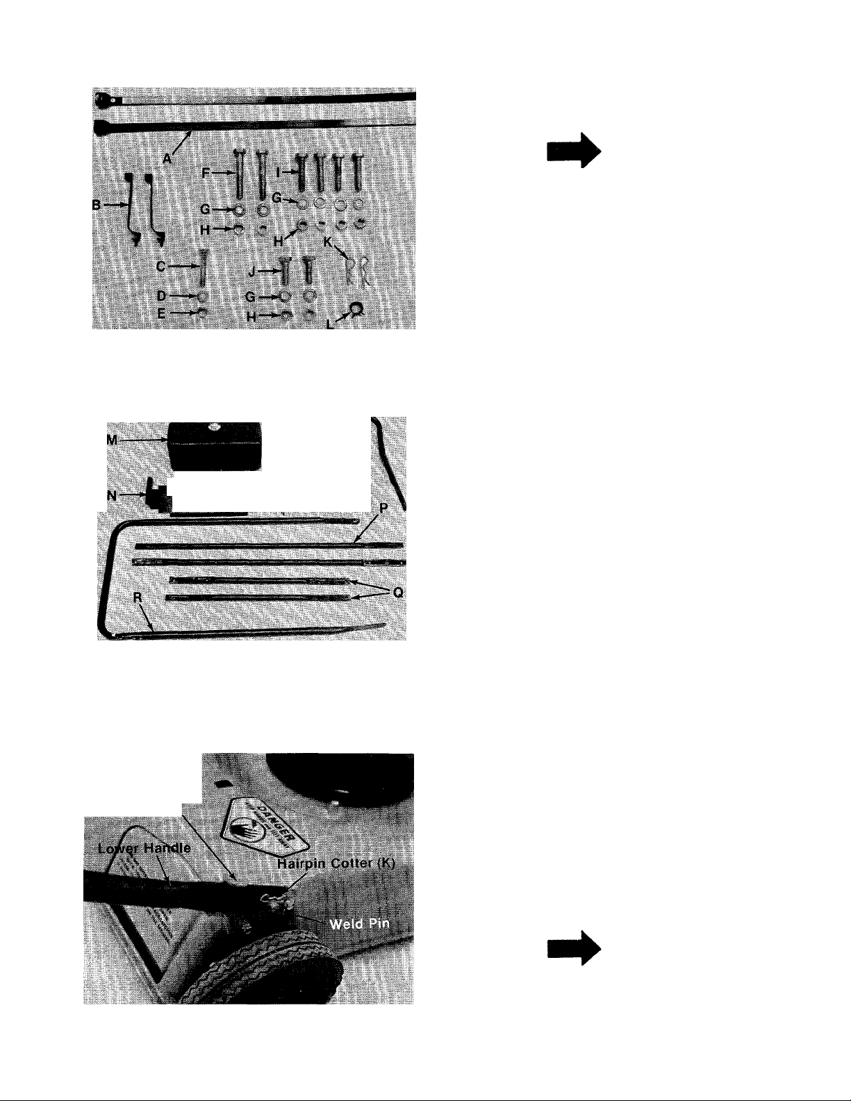
FIGURE 1.
ASSEMBLY
INSTRUCTIONS
NOTE
This unit is shipped WITHOUT GAS
OLINE or OIL. After assembly, see
operating section of this manual for
proper fuel and engine oil recom
mendations.
-Contents of Hardware Pack: (See figure 1)
A (2) Cable Ties (Gas Tank)
(2) Cable Ties (Throttle Control Wire)
B
(1) Hex Bolt V4-20 X 1.50" Long
C
(1) Lock Washer V4" I.D.
D
(1) Hex Nut 1/4-20 Thread
E
F
(2) Hex Bolts 5/16-18 x 1.75" Long
(8) Lock Washers 5/16" I.D.
G
H
(8) Hex Lock Nuts 5/16-18 Thread
I
(4) Hex Bolts 5/16-18 x 1.50" Long
J
(2) Hex Bolts 5/16-18 x .75" Long
K
(2) Hairpin Cotters
L
(1) Hose Clamp (For Gas Line)
FIGURE 2.
Handle Mount
Bracket
-Loose Contents in Carton: (See figure 2)
M (1) Gas Tank
N (1) Gas Tank Bracket
0 (1) Upper Handle
P (2) Upper Struts
Q (2) Lower Struts
R (1) Lower Handle
1. Remove the lawn mower, loose parts, hard
ware pack and literature from the carton.
Make certain all parts and literature have been
removed before the carton is discarded.
2. Extend the throttle control which is attached
to the mower and place on the floor. Be
careful not to bend or kink control wire.
■3. Place lower handle In position over weld pins
in handle mount brackets on deck. Secure by
placing two hairpin cotters (K) in inner hole on
weld pins. See figure 3.
NOTE
FIGURE 3.
It may be necessary to bend the
ends of the lower handle inward
slightly to assure a snug fit against
the bracket mounting area.
Page 5
Outer
Hole
(For Storage)
FIGURE 4.
Inner
Hole
(For OperationL
NOTE
There are two (2) holes in the handle
mount brackets. Place hairpin cot
ter in the inner hole for operation.
The outer hole is for storage. See
figure 4.
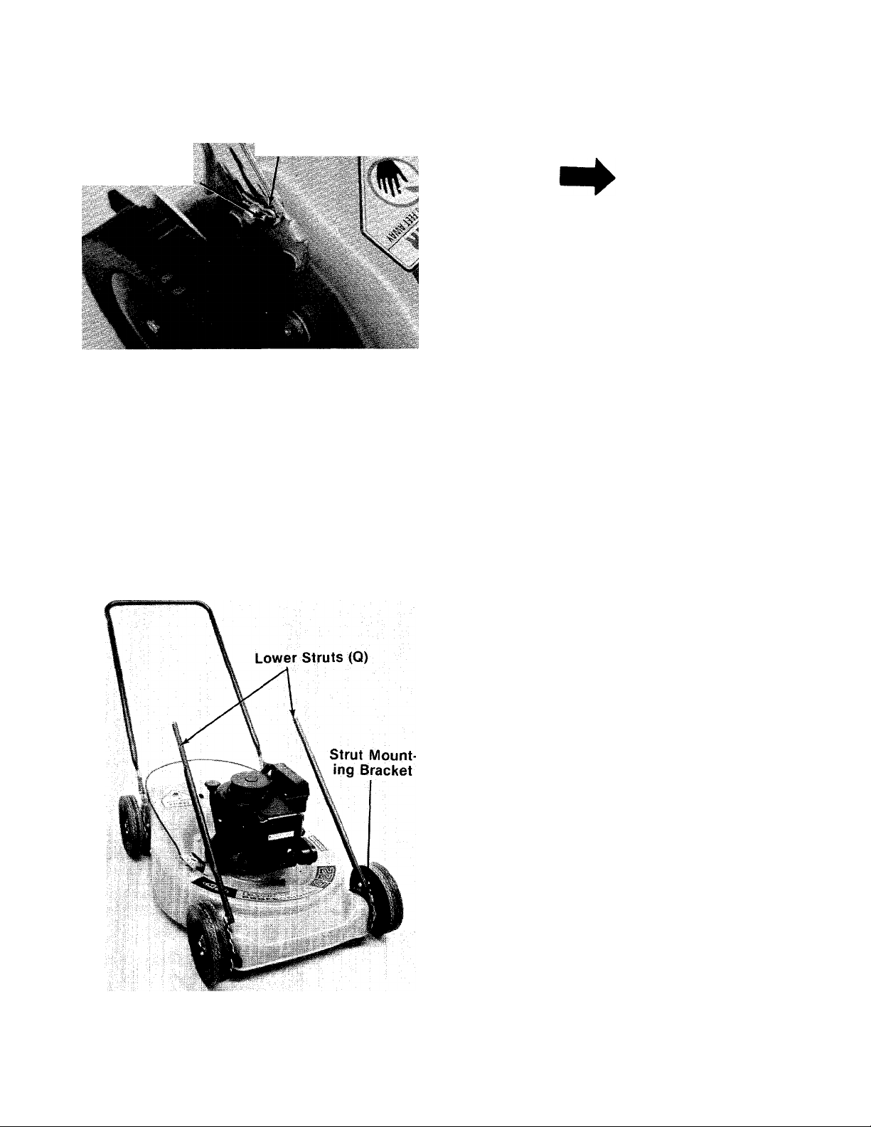
FIGURE 5.
4. Place the lower struts (Q) in position on strut
mounting brackets and secure with hex bolts
(J), lock washers (G) and lock nuts (H). See
figure 5. Do not tighten at this time, only make
finger tight.
Page 6

FIGURE 6.
Gas Tank Mounting
Bracket(N)
5. Place the gas tank mounting bracket (N) over
— the lower struts and start by hand hex bolts (I),
lock washers (G) and hex lock nuts (H). See
figure 6. Do not tighten at this time.
Upper
Handle
FIGURE 7.
Upper
Strut (P)
V2 ■■ Wrenches
6.
Place upper handle in position over lower han
dle. Place upper struts (P) over upper handle
and secure with hex bolts (F), lock washers (G)
and hex lock nuts (H). See figure 7. Tighten
securely. Two Vz" wrenches are required.
Page 7

FIGURE 8.
7. Go back and secure the gas tank mounting
— bracket, upper and lower struts. Tighten
securely with Vi" wrenches. See figure 8.
8. Secure the lower struts to strut mounting
— brackets with two Vz" wrenches. See figure 9.
FIGURE 9.
Mof ;i,
Bra
9. Place the gas tank in position on the gas tank
mounting bracket. Secure in place with two
— plastic cable ties (A). See figure 10. Cut off ex
cess ends.
Page 8

FIGURE 11.
Gas Line
Hose Clamp (L)
With a pair of pliers slip the hose clamp (L)
10.
over the end of gas iine (already on engine).
•Place end of gas line over fuel shut-off valve
(on bottom of tank) and secure with hose
clamp (L). See figure 11.
Throttle
Lock Washer
(D)
11. Place the throttle control in position on the
left hand side of the upper handle. Secure
with hex bolt (C), lock washer (D) and hex nut
------
(E) provided. See figure 5.
NOTE
Reference to left or right side of
machine is from operator’s position
at the handle facing forward.
12. Secure throttle control cable to handle with
------
cable ties (B) provided. See figure 13.
13. Check all nuts and bolts for correct tightness.
Page 9

Upper Frame
ASSEMBLY Grass Catcher
-------
FIGURE 14.
- Lower Frame Ass'
Grass Bag
A
The grass catcher is partially assembled. See
■figure 14.
Upper
Frame
1. Place the upper frame over the lower frame
— assembly as shown in figure 15.
Lower Frame
Assembly
FIGURE 15.
FIGURE 16.
Bottom of Bag
2. Place bag over frame (black plastic side is the
bottom of bag). Upper frame goes to the top of
— bag.
3. Secure bag to frame by slipping plastic chan
nels on bag over frame. See figure 16.
Frame
Plastic Channels
Page 10

TO ATTACH BAG TO MOWER
WARNING
f
DO NOT operate the mower with the
chute door open unless the com
plete grass catcher is properly
mounted on the mower.
FIGURE 17.
Grass Catcher
Frame
-1. Attach the grass catcher frame to grass
catcher hitch bracket on rear of the mower by
hooking grass catcher into hooks on grass
catcher hitch bracket. See figure 17.
2. Lift the rear of grass catcher up. The roller on
the grass catcher will push the chute door on
the mower open. See figure 17.
NOTE
Figure 17 is shown with the chute
door open for photo clarity only.
3. Move the locking lever forward and hook In
— slot on mower. See figures 18 and 19.
FIGUREIS.
FIGUREIS.
A
10
Page 11

TO REMOVE GRASS
CATCHER
1. To remove the grass catcher, lift the rear of
grass catcher, push forward and unhook lock
ing lever.
2. Lift off grass catcher. See figure 20.
OPERATION
DO NOT OPERATE THIS
MOWER WITH THE CHUTE
DOOR OPEN. UNLESS THE
NOTE
For shipping purposes your mower
is set with the wheeis in a low cut
ting height position. For best
results, raise the cutting position
until it is determined which height
is best for your lawn. See adjust
ment section.
BEFORE STARTING
1. Check to see that the handle is in the
operating detent in the brackets on the deck,
and the upstop projections restrict the handle
from moving up and forward. If necessary,
remove the left side from the mounting pin on
the deck bracket. Push inward to decrease the
spacing between the two sides of the handle
until it is slightiy less than the spacing of the
deck brackets. Reinstaii over the mounting
pin and secure the hairpin cotter in the inner
hoies.
2. Fili sump with oii, using a high quaiity
detergent oil classified “For Service SC, SD,
SE or MS.” Use SAE 30, SAE 10W-30 or SAE
10W-40 viscosity grade oil. Nothing should be
added to the recommended oil.
Place engine level. Remove the dipstick. See
figure 22. Fill to full mark on dipstick. Pour slowly.
Capacity 1V4 pints.
COMPLETE GRASSCATCHER
IS PROPERLY MOUNTED ON
THE MOWER.
FIGURE 21.
Keep hands and feet away from the chute area on
cutting deck. See figure 21.
FIGURE 22.
3. Fill fuel tank, using clean, fresh leaded regular
grade automotive gasoline. Fill tank com
pletely.
DO NOT MIX OIL WITH GASOLINE.
11
Page 12

TO START ENGINE
1. Move throttle control lever to “START” posi
tion.
2. Place foot on right side of deck and hold han
dle to prevent tipping the unit. Grasp starter
and puil out rapidly. Return it siowly to the
engine. Repeat if necessary.
NOTE
This engine features a unique
Automatic Choke. In case of
flooding, move control to “STOP”
and puli starter six times. Then
move control to “START” position
and start engine. If engine con
tinues to flood, rotate the carburetor
needle valve 1/8 turn clockwise to
obtain a leaner mixture. See Car
buretor Adjustment in engine man
ual.
CUTTING HEIGHT
An adjusting plate and thumb lever at each wheel
position provides cutting height adjustment. Each
adjusting plate has five holes. Height of cut will
be changed when the thumb lever is moved from
one hole to another. Simply depress the lever
towards wheel and move wheel and lever
assembly to desired position. See figure 23.
Cutting height will be raised as front and rear
ievers are lowered. Cutting height will be lowered
as front and rear levers are raised. All wheels must
be positioned at the same height.
For rough or uneven lawns, move the wheels to a
position which will give a higher cutting height.
This mower is designed to be operated at full
throttle to give you the best cut and do the most
effective job of bagging the cut grass.
TO STOP ENGINE
1. Move throttle control lever to “STOP” posi
tion.
2. Remove spark plug wire from spark plug and
ground to prevent accidental starting while
equipment is unattended.
Be sure that lawn is clear of stones, sticks, wire,
or other objects which could damage lawn mower
or engine. For best results and to insure more
even grass distribution, do not mow when lawn is
excessively wet.
IMPORTANT
After striking a foreign object, stop
the engine. Remove wire from spark
plug, thoroughly inspect the mower
for any damage, and repair the
damage before restarting and
operating the mower.
2 'v-i-
FIGURE 23.
THROTTLE
If adjustment becomes necessary, the throttle
control wire assembly can be reset as follows:
1. Loosen, but do not remove, the screw secur
ing throttle control wire assembly at engine.
See figure 24.
' ■> A ^
ADJUSTMENTS
CAUTION
A
Do not at any time make any adjust
ment to lawn mower without first
stopping engine and disconnecting
spark plug wire.
FIGURE 24.
12
Screw
Throttle
Control Wire
ITT-
Page 13

2. Move throttle control lever on handle to
“FAST” position.
3. Move lever to which control wire is fastened
at engine to full open position. Retighten
screw to secure throttle control wire
assembly.
1. Remove the large bolt and lock washer which
holds the blade and adapter to the engine
crankshaft. See figure 25.
WARNING
i
If any adjustments are made to the
engine while the engine is running
(e.g. carburetor), disengage all
clutches and blades. Keep clear of
all moving parts. Be careful of
heated surfaces and muffler.
CARBURETOR ADJUSTMENTS (Refer to engine
manual for adjustments.)
I
LUBRICATION
IMPORTANT
Always stop engine and disconnect
spark plug wire before cleaning,
lubricating or doing any kind of
work on lawn mower.
Wheels—The wheel bearings should be lubri
cated at least once a season. If the wheels are
removed for any reason, lubricate the surface of
the axle bolt and the inner surface of the wheel
with light oil. A 4 oz. plastic bottle of light oil lubri
cant is available. Order part number 737-0170.
Engine oil may also be used.
Engine—Follow engine manual for lubrication in
structions.
Throttle—Periodically lubricate throttle control
lever and throttle wire assembly with a few drops
of light oil for ease of operation.
Discharge Chute Door Mechanism—The torsion
spring and pivot point should be lubricated
periodically with light oil to prevent any rust or
binding. Doors must work freely.
MAINTENANCE
CUTTING BLADE
A. Removal for Sharpening or Replacement
FIGURE 25.
2. Remove the blade and adapter from the
crankshaft. Be careful not to lose the key op
the crankshaft.
3. If the blade or blade adapter needs replacing,
remove the two small bolts, lock washers and
nuts which hold the blade to the adapter.
B. Sharpening
Remove the cutting blade by following the direc
tions of the preceding section.
When sharpening the blade, follow the original
angle of grind as a guide. It is extremely important
that each cutting edge receives an equal amount
of grinding to prevent an unbalanced blade. An un
balanced blade will cause excessive vibration
when rotating at high speeds and may cause
damage to the mower.
The blade can be tested for balance by balancing
it on a round shaft screwdriver. Remove metal
from the heavy side until it balances evenly. See
figure 26.
^ WARNING \
Be sure to disconnect and ground
the spark plug wire before working
on the cutting blade to prevent
accidental engine starting.
NOTE
It is recommended that the blade
always be removed from the adapter
for the best test of balance.
13
Page 14

FIGURE 26.
C. Reassembly
Before reassembling the blade and the blade
adapter to the unit, iubricate the engine
crankshaft and the inner surface of the blade
adapter with light oil. Lubricating the bolt holes,
bolts and inner surface of the nuts with light oil is
also recommended. A 4 oz. plastic bottle of light
oil lubricant is avaiiable. Order part number
737-0170. Engine oil may also be used.
A
CAUTION
Do not direct the stream of water at
a hot engine as damage to the
engine may result. Be sure spark
plug wire is disconnected.
ENGINE OIL
CHECK OIL LEVEL before starting engine and
after every 5 hours of operation.
ADD oil as necessary to keep level full to full mark
on dipstick.
Engine should be in a level position when check
ing oil.
CHANGE OIL after first 5 hours of operation.
Thereafter change every 25 hours. Change oil
while engine is warm. Oil may be drained thru
drain on bottom of engine. To drain completely,
always place engine level when draining thru the
bottom. Oil capacity 1-1/4 pints. See figure 27.
When replacing the blade, be sure to install the
blade with the side of the blade marked “Bottom”
(or with part number) facing the ground when the
mower is in the operating position. Make certain
key is in place on the crankshaft.
Blade Mounting Torque
3/8" Dia. Bolt 375 in. lb. min., 450 in. lb. max.
5/16" Dia. Bolt 150 in. lb. min., 250 in. lb. max.
To insure safe operation of your unit, ALL nuts
and bolts must be checked periodically for correct
tightness.
DECK
The underside of the mower deck should be
cleaned after each period of use as grass clip
pings, leaves, dirt and other matter will ac
cumulate. This accumulation of grass clippings,
etc., is undesirable as it will invite rust and corro
sion and may cause an uneven discharge of grass
clippings at the next cutting.
The deck may be cleaned by tilting the mower for
ward or on its side and scraping clean with a
suitable tool or by washing with a stream of water
from a garden hose.
FIGURE 27.
AIR CLEANER
CLEAN AIR CLEANER and re-oil element every 25
hours under normal conditions. Clean every few
hours under extremely dusty conditions. Poor
engine performance and flooding usually in
dicates that the air cleaner should be serviced.
See figure 28.
1. Snap off the top cover.
a. WASH foam element in kerosene or a liq
uid detergent and water to remove dirt.
b. DRY foam completely by wrapping and
squeezing in a cloth.
c. SOAK foam with engine oil. Squeeze to
distribute and remove excess oil.
2. Reassemble foam element and cover.
14
Page 15

FIGURE 28.
SPARK PLUG
The spark plug should be cleaned (see figure 29)
and the gap reset to a 0.030-inch ciearance once a
season (see figure 30). Spark piug repiacement is
recommended at the start of each mowing
season; check engine manuai for correct plug
type.
NOTE
Whenever the spark plug is removed
for cieaning, it is advisabie to
replace the spark plug gasket with a
new gasket.
OFF SEASON STORAGE
If the machine is to be inoperative for a period
ionger than 30 days, the foiiowing procedures are
recommended:
1. Working outdoors, drain ail fuel from the fuel
tank. Use a clean dry cloth to absorb the small
amount of fuel remaining in the tank. Then run
the engine until all fuel in the carburetor is ex
hausted.
WARNING
I
Do not drain fuel while smoking, or
if near an open fire.
j
FIGURE 29.
Clean
Electrode
.030"
eeler Gauge
2. Drain all the oil from the crankcase (this
should be done after the engine has been
operated and is still warm). Refill the
crankcase with clean new oil.
3. Disconnect the spark plug wire and remove
the spark plug from the cylinder. Pour about 2
or 3 tablespoons of engine oil into the
cylinder. Turn the engine over several times to
spread out the oil. Replace the spark plug, but
do not connect the wire.
4. Clean the engine and the entire mower
thoroughly.
5. Lubricate all lubrication points.
FIGURE 30.
»park
'■'Spa
Plug
15
Page 16

NOTE
The use of any accessory on this Rotary Mower
other than those manufactured by the mower
manufacturer is not recommended.
WARNING
t
DO NOT operate the mower with the chute door
open unless the complete grass catcher is prop
erly mounted on the mower.
WARNING
The mower shall not be operated without the pro
tective shield on the rear of the mower in place.
NOTE
Under normal usage bag material is subject to wear and should be
checked periodically. Be sure any replacement bag complies with the
mower manufacturer’s recommendations.
For replacement bags, use only factory authorized replacement bag
No. 764-0191.
16
Page 17

111-638A
NOTE
This instruction manual covers various models
and all specifications shown do not necessari
ly apply to your model. Specifications subject
to change without notice or obligation.
Page 18

111-638A
[b££-
PART
746-0425
710-0606
2
749-0378
3
726-0188
4
749-0374 Lower Handle 52 736-0105
5
726-0153
6
7 751-0225 Gas Tank
723-0155
8
710-0380
9
749-0514
10
4 H.P. Engine Tec. Model TVS 105
11
NO.
COLOR
CODE
DESCRIPTION
Throttle Control Ass’y. Comp.
Hex Bolt 1/4-20 X 1.50" Lg.* 49
Upper Handle 50 12323
Plastic Cable Tie
Gas Tank Straps 53 741-0332
Gas Gauge
Hex Bolt 5/16-18 X 1.75" Lg.* 56
Upper Strut N
PARTS LIST FOR MODEL 111-638A
REF.
NEW
NO.
PART
N
48 13406
51 10531
54
55
57
XL 58 10619
12 13773
710-0442 Hex Bolt 5/16-18 X 1.50" Lg.*
13
736-0119
14
712-0158
15
735-0149
16
751-0171 Fuei Shut-Off Valve
17
726-0183
18
19
—
20 12297
21 14426
22 749-0513
710-0118
23
736-0119
24
712-0158
25
12321
26
710-0209
14425
28
14004 -488
29
710-0654
30
Engine Mount Cover Plate 59
60 13407
L-Wash. 5/16" I.D.* 61
Hex Cent. L-Nut 5/16-18 Thd. 62 712-0271
Bushing (Gas Tank)
63
64
Hose Clamp 3/8" I.D.
Gas Line (Comes w/Engine) 65 738-0386
Handle Mount Brkt. Ass’y.
Gas Tank Mounting Brkt. N
Lower Strut
66
N
67 712-0271
Hex Bolt 5/16-18 X .75" Lg.* 68
L-Wash. 5/16" I.D.*
Hex Cent. L-Nut 5/16-18 Thd.
69 731-0449
70
Height Adjuster Ass’y. 71
Comp.—L.H.
72
Hex Sems Bolt 3/8-16 x .62"
Lg.*
strut Mounting Bracket
22" Deck Ass’y.
Hex Wash. Hd. Self-Tap Scr.
73 712-0287
N 74
75
76 710-0776
3/8-16 X .88" Lg.
31 14014 -488
710-0167 Carriage Bolt V4-20 x .50" 78
32
Rear Chute Baffle—L.H. 77
Lg.*
714-0365
33
34
10769
10769
35
736-0217 L-Wash. 3/8" I.D.—H.D.
36
37 710-0459
#6 Hi-Pro Key 5/32 x 5/8" Dia.
Blade Adapter Kit 80 714-0507
Blade Adapter Kit
Hex Bolt 3/8-24 x 1.50" Lg.
79 731-0430
81 14012
82
(Grade 5)
710-0117 Hex Bolt 5/16-24 X 1.00" Lg.
38
(Grade 5)
742-0125
39
736-0119
40
41 712-0123
712-0287
42
736-0329
43
738-0430
44
22" Blade
L-Wash. 5/16" I.D.*
Hex Nut 5/16-24 Thd.*
Hex Nut 1/4-20 Thd.*
L-Wash. 1/4" I.D.*
Shoulder Bolt .50" I.D. x
.605" Lg.
710-0167 Carriage Bolt V4-20 x .50" 91 712-0107
45
Lg.*
712-0287 Hex Nut 1/4-20 Thd.*
46
47 736-0329
L-Wash. 1/4" I.D.*
83
84
85
86
87 13924
88
89
90
92
93
NO.
COLOR
CODE
—488
DESCRIPTION
Rear Chute—R.H.
Push Nut V4" Rod
PART
726-0106
Index Plate
Spring Lever Ass’y. w/Knob
Bell-Wash. 3/8" I.D.
Flanged Ball Bearing
734-1062
710-0427
712-0375
736-0255
Wheel Ass’y. Comp. 8 x 1.75
Hex Bolt 3/8-16 X 2.00" Lg.
Hex Cent. L-Nut 3/8-16 Thd.
Bell-Wash. .50" LD. x 1.14"
O.D.
Pivot Bar
738-0269
—488
732-0346
Shoulder Bolt (3/8-16 Thd.)
Chute Door
Torsion Spring
Hex Sems Nut V4-20 Thd.*
736-0329 L-Wash. 1/4" I.D.*
710-0167
Carriage Bolt V4-20 x .50"
Lg.*
Hinge Pin .250" Dia. x 7.25"
Lg.
736-0329 L-Wash. 1/4 " I.D.*
Hex Sems Nut 1/4-20 Thd.*
710-0258
Hex Bolt 1/4-20 X .62" Lg.*
Rear Flap Ass’y.
736-0219
712-0342
12322
Bell-Wash. .440" I.D.
Hex Jam Nut 3/8-16 Thd.
Height Adjuster Ass’y.
Comp.—R.H.
Hex Nut 1/4-20 Thd.*
736-0329
12296
L-Wash. 1/4" I.D.*
Handle Mount Brkt. Ass’y.
Hex Wash. Hd. Self-Tap Scr.
1/4-20 X .62" Lg.
714-0104
736-0185
Hairpin Cotter 5/16" Dia.
FI-Wash. .406" I.D. x .75"
O.D.
Plastic Roller
Cotter Pin 5/32" Dia. x .75"
Lg.*
-488
710-0703
Grass Catcher—Hitch Brkt.
Carriage Bolt V4-20 x .75"
Lg.*
712-0267
736-0119
13435
738-0140
Hex Nut 5/16-18 Thd.*
L-Wash. 5/16" I.D.*
Cam Lever—Grip Ass’y.
Shid. Bolt
Grass Catcher Lower Frame
Ass’y.
749-0512
764-0191
Grass Catcher Upper Frame
Grass Bag
718-0145 Grip
Hex Cent. L-Nut 1/4-20 Thd.
712-0158
736-0119
Hex Cent. L-Nut 5/16-18 Thd.
L-Wash. 5/16" I.D.*
NEW
PART
N
N
N
N
*For faster service obtain standard nuts, bolts and washers
locally. If these items cannot be obtained locally, order by
part number and size as shown on parts list.
(488—Mack Truck Yellow)
When ordering parts, if color or finish is important use the ap
propriate color code shown above, (e.g. Mack Truck Yellow
Finish —14004 (488).)
19
NOTE: The engine is not under warranty by
the mower manufacturer ... If repairs or
service is needed on the engine, please
contact your nearest author- a—-—
ized engine service outlet. Find It Fast
Check the “Yellow Pages” of In The
your telephone book under Yellow Pages
“Engines—Gasoline.”
---------------
-
Page 19

PARTS INFORMATION
POWER EQUIPMENT PARTS AND SERVICE
Parts and service for all MTD manufactured power equipment are
available through the authorized service firms listed below. All
orders should specify the model number of your unit, part
numbers, description of parts and the quantity of each part re
quired.
BRIGGS AND STRATTON, TECUMSEH AND PEERLESS PARTS
AND SERVICE -
Briggs & Stratton, Tecumseh and Peerless parts and s
should be handled by your nearest authorized engine service i. ..
Check the yellow pages of your telephone directory under the
listing Engines—Gasoline, Briggs & Stratton or Tecumseh
Lauson.
NOTE: If any parts are found to be missing or defective upon assembly of this unit, write to advise the factory so
that immediate replacement can be made.
ALABAMA BiRMINGHAM
Auto Electric & Carburetor Co. . . . 2625 4th Ave. S
ARKANSAS FORT SMITH
Mity Mite Motors, Inc.......................4515 S. 16th St................72901
Sutton's Lawn Mower Shop
CALIFORNIA PORTERVILLE
Billlous
..............................................
J.W. Jewett Co
COLORADO DENVER
Spitzer Industrial Products Co. . .Box 59, 43 W. 9th Ave. ..80201
FLORIDA JACKSONVILLE
Radco Distributors
Small Eng. Dist
GEORGIA EAST POINT
East Point Cycle & Key
ILLINOIS LYONS
Keen Edge Co
INDIANA ELKHART
Parts & Sales Inc
IOWA DUBUQUE
Power Lawn & Garden Equip
LOUISIANA NEW ORLEANS
Suhren Engine Co
MARYLAND TAKOMA PARK
Center Supply Co
MASSACHUSETTS SPRINGFIELD
Morton B. Collins Co....................... 300 Birnie Ave
MICHIGAN LANSING
Lorenz Service Co
Power Equipment Dist
MINNESOTA HOPKINS
Hance Distributing Inc
MISSISSIPPI BILOXI
Biloxi Sales & Service, inc
MISSOURI KANSAS CITY
Automotive Equip. Service
Ross-Frazier Supply Co
Henzier, Inc......................................2015 Lemay Ferry Road63125
NEW JERSEY BELLMAWR
Lawnmower Parts Inc
NEW YORK CARTHAGE
Gamble Dist., Inc
..................................
..........................
................................
...................
..................................
.............................
...........................
...........................
...........................
....................
....................
.................
.....................
.............................
NORTH LITTLE ROCK
...........
Rt. 4, Box 368
75 North D Street
SAN FRANCISCO
981 Folsom St..............94107
4909 Victor St.
Box 5459
OPA LOCKA
2351 N.W. 147th St. . . .33054
2834 Church St
8615 Ogden Ave
2101 Industrial Pkwy.. .46514
.........
2551 J.F. Kennedy .... 52001
8330 Earhart Bivd.........70118
6867 New Hampshire
Ave
................................
2500 S. Pennsylvania . .48910
MOUNT CLEMENS
36463 South Gratiot. .. 48043
420 Excelsior Ave. W. . 55343
.............
506 Caillavet St
............
3117HolmesSt
ST. JOSEPH
8th and Monterey
ST. LOUIS
717 Creek Rd
West End Ave................13619
..............
...............
..........
......................
............
..........
..............
............
...............
..........
.................
30344
60534
01107
39533
64503
35233
72117
93257
32207
20012
64109
08030
NORTH CAROLINA GOLDSBORO
Smith Hardware Co
Dixie Sales Company
OHIO CARROLL
Stebe’s Mid-State Mower Supply . Box 366, 71 High St... .43112
Bleckrie, inc.....................................7900 Lorain Ave
National Central
Burton Supply Co............................1301 Logan Ave.
OKLAHOMA MUSKOGEE
Victory Motors, Inc
Forest Sales Inc
OREGON PORTLAND
Kenton Supply Co
PENNSYLVANIA CHESTER
Stull Equipment Corp
EECOInc............................................ 4021 N.6thSt
Thompson Rubber Co
Bluemont Co
Frank Roberts & Sons
TENNESSEE KNOXVILLE
Master Repair Service
American Sales & Service, Inc. .. . 3035-43 Bellbrook ... .38116
TEXAS DALLAS
Marr Brothers, Inc............................ 423 E. Jefferson
Woodson Sales Corp....................... 1702 N. Sylvania
Bullard Supply Co
Catto & Putty, Inc.............................414 Live Oak..................78298
UTAH SALT LAKE CITY
A-1 Engine & Mower Co
VERMONT BURLINGTON
Vermont Hdwe. Co. Inc
VIRGINIA ASHLAND
RBI Corp...........................................Lake Ridge Park
WASHINGTON SEATTLE
Bailey’s Inc.......................................1414 14th Ave
WEST VIRGINIA CHARLESTON
Young's, Inc
WISCONSIN MARSHFIELD
Power Pac.........................................301 E. 29th St
.........................
......................
..............................
..........................
...............................
...........................
......................
.....................
...........................................................
...................
.....................
...........................
..................
...................
.....................................
515 N. George St.
GREENSBORO
335 N. Green ....
CLEVELAND
WADSWORTH
687 Seville Rd
YOUNGSTOWN
Box 929
605 S. Cherokee ...... 74401
OKLAHOMA CITY
6415N.OIie
8216 N. Denver Ave. . . .97217
742 W. Front St
HARRISBURG
PHILADELPHIA
5222-24 N. Fifth St
PITTSBURGH
PUNXSUTAWNEY
R.D. 2
2000 Western Ave
MEMPHIS
FORT WORTH
HOUSTON
2409 Commerce St. .. 77003
SAN ANTONIO
437 E. 9th St
180 Flynn Ave
101 Cedar Run Dr
233 Virginia St., E
........................
...............................
.............
................
.....................
..............
..................
.........
11125 Frankstown Rd. .15235
.......
37921
...........
..........
76111
.................
...............
...............
................
.........
........
84111
05401
25301
54449
.27530
.27402
44102
44281
44501
73116
19013
17110
19120
'
75203
23005
98102
WARRANTY PARTS AND SERVICE POLICY
The purpose of warranty is to protect the customer from defects in workmanship and materials, defects which are NOT detected at the
time of manufacture. It does not provide for the unlimited and unrestricted replacement of parts. Use and maintenance are the respon
sibility of the customer. The manufacturer cannot assume responsibility for conditions over which it has no control. Simply put, if it’s
the manufacturer’s fauit, it’s the manufacturer’s responsibiiity; if it’s the customer’s fauit, it’s the customer’s responsibility.
CLAIMS AGAINST THE MANUFACTURER’S WARRANTY
INCLUDES:
1. Replacement of Missing Parts on new equipment.
2. Replacement of Defective Parts within the warranty period.
3. Repair of Defects within the warranty period.
Aii claims MUST be substantiated with the following
information:
1. Model Number of unit involved.
2. Date unit was purchased or first put into service.
3. Date of failure.
4. Nature of failure.
MTD PRODUCTS • 5965 GRAFTON ROAD • P.O. BOX 36900 • CLEVELAND, OHIO 44136
 Loading...