

Page 1
$1.00
N
owicirs GUIDE
ASSEMBLY • OPERATION • MAINTENANCE • PARTS
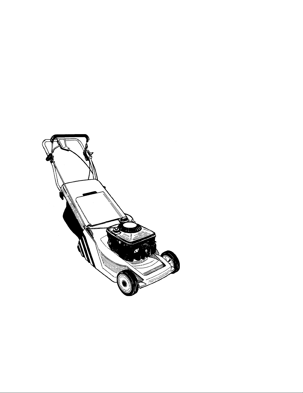
18"
(Model 638R Shown)
ROTARY
MOWERS
Model Numbers
111-604R000
111-614R000
121-626R000
121-628R000
121-636R000
121-638R000
PRINTED IN U.S.A.
FORM NO. 770-7389F
Page 2

IMPORTANT
THIS SYMBOL POINTS OUT IMPORTANT SAFETY INSTRL CTIONS WHICH, IF NOT FOLLOWED, COULD ENDANGER THE PERSONAL SAFETY
AND/OR PROPERTY OF YOURSELF AND OTHERS. HEfiQ AND FOLLOW ALL INSTRUCTIONS IN THIS MANUAL BEFORE AHEMPTING
TO OPERATE YOUR LAWN MOWER. FAILURE TO COM >LY WITH THESE INSTRUCTIONS MAY RESULT IN PERSONAL INJURY. WHEN
▲
YOU SEE THIS SYMBOL- a HEED ITS WARNING.
RULES FOR SAFE OPERATION
â
DANGER: with any type of power equi iment, carelessness or error on the part of the operator can result in serious
Your lawn mower was built to be operated according to the rules for safe operation in this manual. As
A
TRAINING
1. Read this owner’s guide carefully in its entirety before a (tempting
to assemble or operate this machine. Be completely fai liliar with
the controls and the proper use of this machine before operating
it. Keep this manual in a safe place for future and regular reference
and for ordering repiacement parts.
2. Your rotary mower is a precision piece of power equip nent, not
a plaything. Therefore, exercise extreme caution at all tli nes. Your
unit has been designed to perform one job: to mow jrass. Do
not use it for any other purpose.
3. Never allow children under 14 years old to operate a pow jr mower.
Children 14 years old and over should only operate mo m under
close parental supervision. Only persons well acquainted with these
rules of safe operation should be allowed to use you ■ mower.
4. Keep the area of operation clear of all persons, particu arly small
children and pets. Stop engine when they are in the /icinity of
your mower to help prevent blade contact or thrown object in
jury. Although the area of operation should be completi ly cleared
of foreign objects, an object may have been overlooked and could
be accidently thrown by the mower in any direction md cause
serious personal injury to the operator or any others îllowed in
the area.
PREPARATION
Thoroughly inspect the area where the equipment is to be used.
Remove all stones, sticks, wire, bones and other foreign objects
which could be picked up and thrown by the mower in any direc
tion and cause serious personal injury to the operator or any others
allowed in the area. Plan your mowing pattern to avoid discharge
of material toward roads, sidewalks, bystanders and the like.
Always wear safety glasses or eye shields during operati >n or while
2.
performing an adjustment or repair, to protect eyes fmm foreign
objects that may be thrown from the machine in anv direction.
3. Wear sturdy, rough-soled work shoes and close-fitting slacks and
shirts. Shirts and pants that cover the arms and legs and steel
toed shoes are recommended. Do not wear loose fittiig clothes
or jewelry. They can be caught in moving parts. Nev er operate
a unit in bare feet, sandals, or sneakers.
Before working with gasoline, extinguish all cigarettes, cigars, pipes
4.
and other sources of ignition. Check the fuel level beft re starting
the engine. Gasoline is an extremely flammable fuel. Do not fill
the gasoline tank indoors, while the engine is runnir g, or until
engine has been allowed to cool for at least two ml lutes after
running. Replace gasoline cap securely and wipe off any spilled
gasoline before starting the engine as it may caus i a fire or
explosion.
5. Disengage the self-propelled mechanism or drive clutih on units
so equipped before starting the engine.
6. The blade control handle is a safety device. Never attemt t to bypass
its operation. Doing so makes the safety device inopsrative and
may result in personal injury through contact with t ae rotating
blade. The blade control handle must operate easily in both direc
tions and automatically return to the disengaged pos:ition when
released.
7. Never attempt to make a wheel or cutting height adjus ment while
the engine is running.
8. Never operate the mower in wet grass. Always be s ire of your
footing. A slip and fall can cause serious personal injury. Keep
a firm hold on the handle and walk, never run. Mow onl; ' in daylight
or in good artificial light.
injury. If you violate any of these rules, you may cause serious injury to yourself or others.
OPERATION
A
A
9. For your safety, use the slope gauge included as part of this manual
to measure slopes before operating this unit on a sloped or hilly
area. If the slope is greater than 15° as shown on the slope gauge,
do not operate this unit on that area or serious injury could result.
1. Do not change the engine governor settings or overspeed the
engine. Excessive engine speeds are dangerous.
2. Do not put hands or feet near or under rotating parts. Keep clear
of the discharge opening at all times as the rotating blade can
cause injury.
3. Stop the blade when crossing gravel drives, walks or roads.
4. After striking a foreign object, stop the engine, remove the wire
from the spark plug, and thoroughly inspect the mower for any
damage. Repair the damage before restarting and operating the
mower.
5. If the equipment should start to vibrate abnormally, stop the engine
and check immediately for the cause. Vibration is generally a warn
ing of trouble.
6. Shut the engine off and wait until the blade comes to a complete
stop before removing the grass catcher or unclogging the chute.
The cutting blade continues to rotate for a few seconds after the
engine is shut off. Never place any part of the body in the blade
area until you are sure the blade has stopped rotating.
Before cleaning, repairing or inspecting, make certain the blad
7.
and all moving parts have stopped. Disconnect the spark plug wire,
and keep the wire away from the spark plug to prevent accidental
starting.
Do not run the engine indoors.
8.
Never cut grass by pulling mower toward you. Mow across the
9.
face of slopes, never up-and-down. Exercise extreme caution when
changing direction on slopes. Do not mow excessively steep slopes.
Always be sure of your footing. A slip and fall can cause serious
personal injury.
10. Never operate mower without proper guards, plates or other safety
protective devices in place.
11. Muffler and engine become hot and can cause a burn. Do not
touch.
12. Do not operate this mower with the chute door open, unless the
complete grass catcher or chute deflector is properly mounted
on the mower.
MAINTENANCE AND STORAGE
1. Check the blade and engine mounting bolts at frequent intervals
for proper tightness. Also visually inspect blade for damage (e.g.
bent, cracked). Replace with blade which meets original equip
ment specifications.
2. Keep all nuts, bolts, and screws tight to be sure the equipment
is in safe working condition.
3. Never store the mower with gasoline in the tank or gas containers
inside of a building where fumes may reach an open flame or spark
(e.g. gas hot water heater). Allow the engine to cool before stor
ing in any enclosure.
4. To reduce fire hazard, keep the engine free of grass, leaves and
excessive oil.
5. Check the grass catcher bag frequently for wear or deterioratio''
Replace a worn or damaged bag immediately. For safety prott
tion, replace only with new bag meeting original equipment
specifications.
Page 3
The use of any accessory on this Rotary Mower other than those manufactured by the mower manufacturer is not recom
mended.
WARNING: DO NOT operate the mower without the entire grass catcher or chute deflector in place. DO
A
NOTE: Under normal usage bag material is subject to wear and should be checked periodically. Be sure any replacement
bag complies with the mower manufacturer’s recommendations. For replacement bags, use only factory authorized replace
ment bag.
WARNING: This unit is equipped with an internal combustion engine and should not be used on or near any unimproved
forest-covered, brush-covered or grass-covered land unless the engine’s exhaust system is equipped with a spark arrester
meeting applicable local or state laws (if any). If a spark arrester is used, it should be maintained in effective working order
by the operator.
In the State of California the above is required by law (Section 4442 of the California Public Resources Code). Other states
may have similar laws. Federal laws apply on federal lands. A spark arrester for the muffler is available through your nearest
engine authorized service dealer or contact the service department, P.O. Box 360900, Cleveland, Ohio 44136.
NOT operate the mower without the protective shieid on the rear of the deck in piace.
SET-UP INSTRUCTIONS
IMPORTANT: This unit is shipped WiTHOUT
GASOLiNE or OiL. After assembiy, service engine
with gasoline and oil as instructed in the separate
engine manual packed with your unit.
NOTE: Reference to right or left hand side of the
mower is observed from the operating position.
1. Remove the lawn mower from the carton by open
ing the top flaps and lifting the unit out. Be careful
of the staples. Make certain all parts and literature
have been removed from the carton before the car
N
ton is discarded.
Pull up and back on the handle to raise the handle
2.
until it locks into operating position. Tighten the
hand knobs which secure the upper and lower
handles.
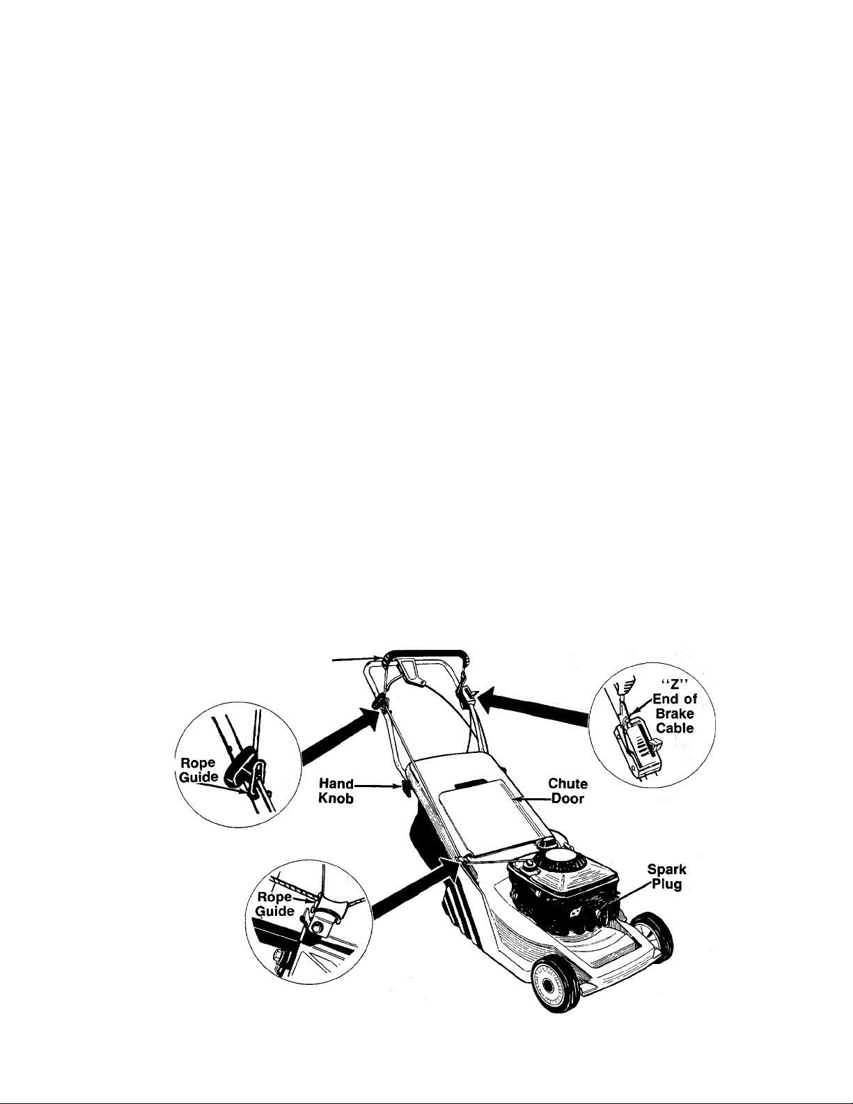
3. Hook the brake cable into the blade control handle
from the inside to the outside as shown.
Blade Control
Handle
4. With the spark plug wire disconnected and moved
away from the spark plug, depress the blade con
trol handle and pull the starter rope out of the
engine. Slip the starter rope into the rope guide
on the upper handle. Then slip the rope into the
rope guide mounted on the right rear side of the
mower.
5. To attach the grass catcher, lift the chute door on
the back of the mower. Place grass catcher in posi
tion. The grass catcher must rest firmly on the
lower handle of the mower. Release the chute
door. Make certain the magnets on the grass
catcher bag secure the chute door firmly.
To remove the grass catcher, raise the chute door and
lift the grass catcher up. Release the chute door.
FIGURE 1.—-Self-Propelled Model Shown
Page 4
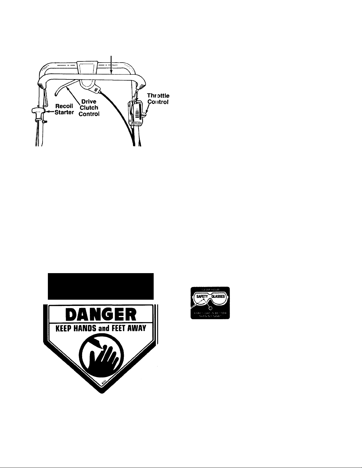
CiONTROLS
Blade Control Handle
FIGURE 2.—Self-Propelled Model Shown
BLADE CONTROL HANDLE
WARNING: This control mechanis n is a
safety device. Never attempt to byp ass its
A
The blade control handle is located on the uppor han
dle of the mower. See figure 2. The blade control han
dle must be depressed in order to operate the unit.
Release the blade control handle to stop the engi ne and
blade.
operations.
WARNING: The blade will be rotating
A
THROTTLE CONTROL
The throttle control is located on the side of the upper
handle. It is used to regulate the engine speed.
A
RECOIL STARTER
The recoil starter handle is attached to the handle. See
figure 2. Stand behind the unit in the operating posi
tion to start the unit.
DRIVE CLUTCH CONTROL
(Self-Propelled Models Only)
Squeezing the drive clutch control engages the drive
mechanism to the rear wheels. Releasing the clutch
control stops the rear wheels from driving. Release the
drive clutch control to slow down when negotiating an
obstacle, making a turn or stopping. See figure 2.
whenever the engine is running.
WARNING: The throttle control cannot be
used to stop the engine.
OPERATION
TO REDUCE THE RISK OF INJURY. DO NOT
OPERATE MOWER UNLESS REAR TRAILING
SHIELD AND THIS GUARD OR ENTIRE
GRASS CATCHER IS IN ITS PROPER PLACE.
FIGURE 3.
Keep hands and feet away from the chute area on cut
ting deck. See figure 3.
The operation of any lawn mower can result in
foreign objects being thrown into the eyes, which
can result in severe eye damage.
Always wear safety glasses or eye
shields. We recommend wide vision
safety mask for over spectacles or
standard safety glasses.
NOTE: For shipping purposes your mower is set with
the wheeis in a iow cutting height position. For best
resuits raise the cutting position until it is determined
which height is best for your lawn. See cutting height
adjustment section.
GAS AND OIL FILL-UP
Service the engine with gasoline and oil as instructed
in the separate engine manual packed with your
mower. Read instructions carefully.
WARNING: Never fill fuel tank indoors,
with engine running or until the engine has
A
been allowed to cool for at least two
minutes after running.
Page 5
BEFORE STARTING
1. Attach spark plug wire to spark plug. Make certain
■N
the metal loop on the end of the spark plug wire
(inside the rubber boot) is fastened secureiy over
the metai tip on the spark piug. See figure 4.
Metal Loop
on Spark
Plug Wire
FIGURE 4.
2.
Open fuel shut-off valve (if so equipped). Refer to
separate engine manual.
Before each use, check for proper drive clutch
operation by performing the foilowing before start
ing the engine:
With the drive clutch control released, push mower
forward. It should move freely. Pull mower
backward. It should move freely.
If it does not and the rear wheels tend to lock up,
the clutch may not be releasing completely. Do not
start the engine until corrections have been made.
Check the control cable for severe bend, kinks and
binding, or grass build-up in the pulley groove. Cor
rect and adjust as required.
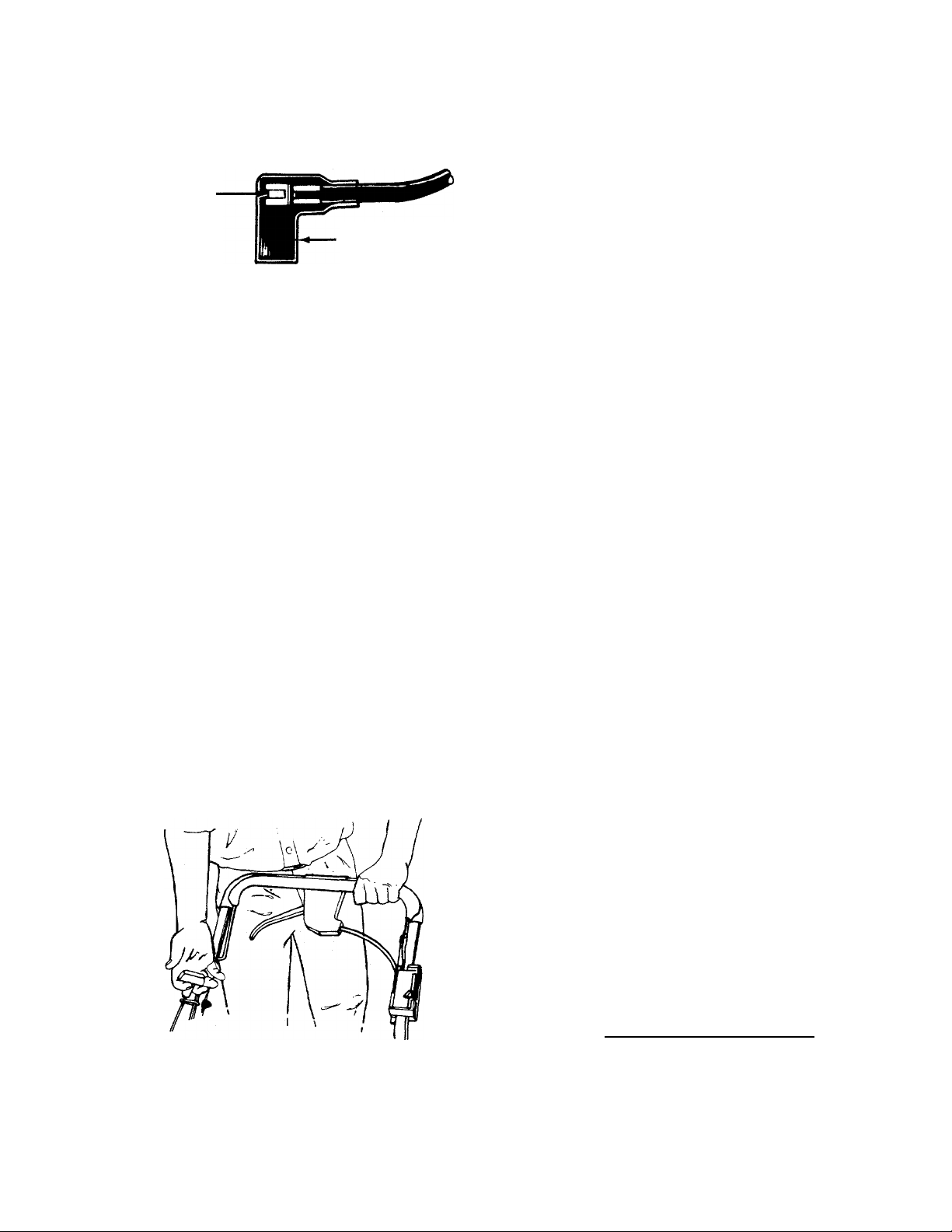
TO START ENGINE AND ENGAGE BLADE
N
A
1.
2.
WARNING: When starting self-propelled
units for the first time, face the mower
against a soiid object such as a wall, fence,
etc. Start the unit, and if it shows any signs
of motion with the drive ciutch control
disengaged, shut the engine off im
mediately.
Move throttle control lever all the way forward.
Standing behind the unit, depress the blade con
trol handle and hold it against the upper handle
as shown. See figure 5.
Rubber Boot
4. After engine starts, rnove throttle control to desired
engine speed.
NOTE: If any problems are encountered, refer to the
Trouble Shooting Guide on page 16.
TD STDP ENGINE AND BLADE
1. Move throttle control lever to SLOW position.
2. Release the blade control handle to stop the
engine and blade.
WARNING: The blade continues to rotate
for a few seconds after the engine is shut
A
3. Disconnect the spark plug wire and ground it
off.
against the engine to prevent accidental starting
while equipment is unattended.
USING YDUR RDTARY MDWER
WARNING: Never operate your unit without
either the rear chute door or entire grass
A
Be sure that lawn is clear of stones, sticks, wire, or other
objects which could damage lawn mower or engine.
Such objects could be accidently thrown by the mower
in any direction and cause serious personal injury to
the operator and others.
For the best results, do not cut wet grass because it
tends to stick to the underside of the mower, prevent
ing proper bagging of grass clippings, and could cause
you to slip and fall. New grass, thick grass or wet grass
may require a narrower cut. Blade speed should be ad
justed to the condition of the lawn.
For best results, cut off one-third or less of the total
length of the grass. Lawn should be cut in the fall as
long as there is growth.
This mower is designed to be operated at full throttle
to give you the best cut and do the most effective job
of bagging the cut grass.
A
catcher assembly in place.
WARNING: If you strike a foreign object,
stop the engine. Remove wire from spark
plug, thoroughly inspect the mower for
any damage, and repair the damage before
restarting and operating the mower. Exten
sive vibration of the mower during opera
tion is an indication of damage. The unit
shouid be promptiy inspected and
repaired.
FIGURE 5.—Self-Propelled Model Shown
3. Grasp the recoil starter handle and pull back rapid
ly, extending rope fully. Return it slowly to the rope
guide.
A
ADJUSTMENTS
WARNING: Do not at any time make any
adjustment to lawn mower without first
stopping engine and disconnecting spark
piug wire.
Page 6

CUTTING HEIGHT ADJUSTMENT
The height adjustment knob is iocated on the left side
of the deck. Turn the knob clockwise to lower c utting
height; turn it counterclockwise to raise the c utting
height. See figure 6.
For rough or uneven lawns, raise the cutting f eight.
THRDTTLE CONTROL ADJUSTMENT
If the throttle control requires adjustment or if it has
been replaced, adjust the throttle control as follows.
1. Remove the screw shown in figure 8. Remove the
cable clamp from the cable.
2. Push the throttle control lever on the handle all the
way forward to CHOKE position. Make certain the
throttle control lever remains in this position.
3. Push the control lever on the engine as far toward
the rear of the engine as it will go. Secure the cable
in this position with the cable clamp and screw.
Cable
Clamp
FIGURE 6.
DRIVE CLUTCH CONTROL ADJUSTMENT
(Self-Propelled Models Only)
Use the adjustment wheel located in the clutch c ontrol
housing to tighten the drive belt if mower does n( it selfpropel with the drive clutch control engaged, or i f drive
belt is slipping (unit hesitates while engine maintains
the same speed). See figure 7.
In addition, the adjustment wheel may also be used to
determine the position in which the drive elute i con
trol is engaged. If it is more comfortable to have the
drive engaged with the lever further away from th 3 han
dle, tighten the drive belt.
Make certain to retest the unit for neutral as inst ucted
in the Operation Section. Move the adjustment wheel
in the opposite direction to loosen the drive belt if
necessary.
FIGURE 8.
CARBURETOR ADJUSTMENTS
WARNING: If any adjustments are made to
the engine while the engine is running (e.g.
A
Minor carburetor adjustments may be required to
compensate for differences in fuei, temperature,
altitude and load. To adjust carburetor, refer to the
carburetor), keep clear of all moving parts.
Be careful of heated surfaces and muffler.
separate engine manual packed with your mower.
NOTE: A dirty air cieaner wiii cause an engine to run
rough. Be certain air cleaner is clean and attached to
the carburetor before adjusting carburetor. Refer to the
separate engine manual.
LUBRICATION
WARNING: Always stop engine and
disconnect spark piug wire before clean
A
ing, lubricating or doing any kind of work
on iawn mower.
FIGURE 7.
Blade Control—Lubricate the pivot points on the blade
control handle and the brake cable at least once a
season with light oil. The blade control must operate
freely in both directions.
Page 7

Chute Door—The torsion spring and pivot point should
be lubricated periodically with light oil to prevent any
rust or binding. Deflector must work freely.
^ Wheels—Mower is provided with ball bearing wheels.
Lubricate at least once a season with light oil. Also, if
the wheels are removed for any reason, lubricate the
surface of the axle bolt and the inner surface of the
wheel with light oil. A 4 oz. plastic bottle of light oil lubri
cant is available. Order part number 737-0170. Engine
oil may also be used.
Engine—Follow engine manual for lubrication in
structions.
Throttle—Periodically lubricate throttle control lever
and throttle wire assembly with a few drops of light oil
for ease of operation.
Transmission—The transmission is pre-lubricated and
sealed at the factory. It does not require checking. If
disassembled for any reason, fill with 2 ounces of
Alvania grease, part number 737-0168.
The blade can be tested by balancing it on a round shaft
screwdriver. Remove metal from the heavy side until
it balances evenly.
Before reassembling the blade and the blade adapter
to the unit, lubricate the engine crankshaft and the inner
surface of the blade adapter with light oil. Lubricating
the bolt holes, bolts and inner surface of the nuts with
light oil is also recommended. A 4 oz. plastic bottle of
light oil lubricant is available. Order part number
737-0170. Engine oil may also be used.
When replacing the blade, be sure to install the blade
with the side of the blade marked “Bottom” (or with
part number) facing the ground when the mower is in
the operating position.
Blade Mounting Torque
Center Bolt and Blade Adapter Bolts:
375 in. lb. min., 450 in. lb. max.
To insure safe operation of your unit, all nuts and bolts
must be checked periodically for correct tightness.
MAINTENANCE
WARNING: Be sure to disconnect and
ground the spark plug wire before per
A
NOTE: When tipping the unit, empty the fuel tank and
keep engine spark plug or muffler side up.
TROUBLE SHOOTING
Refer to page 16 of this manual for trouble shooting
information.
CUTTING BLADE
When removing the cutting blade for sharpening or
replacement, protect hands by using heavy gloves or
a rag to grasp the cutting blade. Remove the bolt and
bell washer which hold the blade and adapter to the
engine crankshaft. Remove the blade and adapter from
the crankshaft.
If the blade or blade adapter needs replacing, remove
the two small bolts, lock washers and nuts which hold
the blade to the adapter.
A
When sharpening the blade, follow the original angle
of grind as a guide. It is extremely important that each
cutting edge receives an equal amount of grinding to
prevent an unbalanced blade. An unbalanced blade will
cause excessive vibration when rotating at high speeds,
may cause damage to the mower and could break,
causing personal injury.
It is recommended that the blade always be removed
from the adapter for the best test of balance.
forming any repairs or maintenance.
WARNING: Periodically inspect the blade
adapter for cracks, especially if you strike
a foreign object. Replace when necessary.
DECK
The underside of the mower deck should be cleaned
after each use to prevent a buildup of grass clippings,
leaves, dirt or other matter. If this debris is allowed to
accumulate, it will invite rust and corrosion, and may
cause an uneven discharge of grass clippings at the
next cutting.
The deck may be cleaned by tilting the mower and
scraping clean with a suitable tool (make certain the
spark plug wire is disconnected).
ENGINE
Refer to the separate engine manual for engine
maintenance instructions.
Maintain engine oil as instructed in the separate
engine manual packed with your unit. Read and follow
instructions carefully.
Service air cleaner every 25 hours under normal con
ditions. Clean every few hours under extremely dusty
conditions. Poor engine performance and flooding
usually indicates that the air cleaner should be ser
viced. To service the air cleaner, refer to the separate
engine manual packed with your unit.
The spark plug should be cleaned and the gap reset
once a season. Spark plug replacement is recom
mended at the start of each mowing season; check
engine manual for correct plug type and gap
specifications.
Clean the engine regularly with a cloth or brush. Keep
the cooling system (blower housing area) clean to per
mit proper air circulation which is essential to engine
performance and life. Be certain to remove all grass,
dirt and combustible debris from muffler area.
Page 8

BELT REMOVAL AND REPLACEMENT
1. Disconnect the spark plug wire and ground it
against the engine.
2. Drain the fuel tank or place a piece of plastic
beneath the cap to prevent gasoline leakage.
3. Tip the mower back on its handle. Block securely.
4. Remove the rear belt baffle by removing fivu self
tapping screws. See figure 9.
Rear Belt
Baffle
FIGURE 9.
5. Roll the belt off the transmission pulley. Re move
the belt from between the idler pulley and belt
guard. See figure 10.
6. Remove the belt from the pulley on the engine
crankshaft, and pull it over the blade.
Bsit
Guard
Transmission
Pulluy
OFF-SEASON STORAGE
The following steps should be taken to prepare lawn
mower for storage.
1. Clean and lubricate mower thoroughly as de
scribed in the lubrication instructions.
2. Refer to engine manual for correct engine storage
instructions.
3. Coat mower’s cutting blade with chassis grease
to prevent rusting.
4. Store mower in a dry, clean area.
NOTE: When storing any type of power equipment in
an unventilated or metal storage shed, care should be
taken to rust-proof the equipment. Using a light oil or
silicone, coat the equipment, especially cables and all
moving parts.
HANDLE STORAGE
The handle may be folded away completely for storage.
1. Disconnect the spark plug wire and move away
from the spark plug.
2. Remove the starter rope from both rope guides.
Unhook the brake cable from the blade control
handle. Remove the grass bag.
3. Loosen the hand knobs. Fold the upper handle
down.
4. Pull outward on the handle locks on each side of
the lower handle, and lift the sides of the lower han
dle past the locks as shown in figure 11. Fold the
lower handle forward.
To return the mower to operating position, follow “Set-
Up Instructions” on page 3.
Idler
Pulley
FIGURE 10.
7. Reassemble in reverse order with the new belt.
NOTE: When reassembling the rear belt baffle, make
certain the belt keeper is outside of the belt, at>d the
edge of the rear belt baffle is between the rear chute
baffle and the rear panel. Make certain to tighten a II nuts
and bolts securely. If plastic was placed under tf e gas
cap, be certain to remove it.
Handle
Lock
FIGURE 11.
Page 9

Models 604R, 614R, 626R, 628R, 636R and 638R
NOTE: The engine is not under warranty by
the mower manufacturer. ..If repairs or
service is needed on the engine, please
contact your nearest author
ized engine service outlet.
Check the “Yellow Pages” of
your telephone book under
“Engines—Gasoline.”
Find It Fast
In The
Yellow Pages
“N
PARTS LIST FOR MODELS 604R, 614R, 626R, 628R, 636R AND 638R LAWN MOWERS
REF.
NO.
PART
NO.
CODE DESCRIPTION
1 710-0255 Truss Mach. Scr. V4-20 x .75"
Lg-
REF.
NO.
11
12 17800
2 736-0329 L-Wash. V4" I.D.* 13 710-0969
720-0236 N
3
4 732-0675 N
738-0137 Shid. Bolt .342" Dia. x .268" Lg.
5
6 738-0811
7 731-1128 N
747-0590
8
747-0589 N
747-0803 N
9
747-0802 N
714-0104
10
Plastic Knob
Ball Plunger
N
Height Adjuster Spindle
Spindle Guide
N
Height Adjustment Rodf
Height Adjustment Rodft
Height Adjustment Linkf
Height Adjustment Linktt
Int. Cotter Pin 5/16" Dia.
14
15 738-0102
16
17
18 17802
19 710-0969
20
(604R, 614R) 21
714-0507 Cotter Pin 3/32" Dia. (626R, 22
628R, 636R, 638R) 23
PART
NO.
CODE
17521 N
736-0105
734-1670 N
731-0981A
710-0603
741-0180
736-0232
736-0326
DESCRIPTION
Front Axle Ass’y-
N
Axle Mounting Plate
Truss Mach. Hi-Riser Tap Scr.
#12 X 1" Lg.
Bell-Wash. .38" I.D. x .88"
ShId. Bolt .498" Dia. x 1.45"
Front Wheel Ass’y- Comp.
Hub Cap
Height Adj. Spindle Brkt.
Truss Mach. Hi-Riser Tap Scr.
#12 X 1" Lg. (604R, 614R)
Hex B-Tap 5/16-18 x .5" Lg.
(626R, 628R, 636R, 638R)
Ball Bearing
Wave Wash. .53" I.D.
FI-Wash. .51" I.D. x 1" O.D.
tModels 614R, 636R and 638R Only.
ttModels 604R, 626R and 628R Only.
Page 10

Models 604R and (M4R
This instruction manuai covers various models,
and all specifications shown do not necessarily
apply to your model. Specifications subject to
change without notice or obligation.
10
Page 11

Models 604R and 614R
PARTS LIST FOR MODELS 604R AND 614R LAWN MOWERS
REF.
NO.
10
11 750-0812 N Pivot Spacer—R.H.
12 750-0813
16
18
20
21 731-1118 N
31
32 710-0642 Hex TT-Tap Scr. 1/4-20 x .75"
33 748-0190 Spacer .508" I.D. x .688" O.D.t
34
36 750-0151 Spacer .55" I.D. x .755" O.D.
37 720-0241 N
38 736-0451 N Saddle Washer .32" I.D.
39
40
41
42 749-0816 N Upper Handle
43
44 712-0267 Hex Nut 5/16-18 Thd.*
45
46
47
48 732-0646
49 17748
50 17749 N Handle Lock—L.H.
51
52 732-0654
53 732-0653
54 747-0773
55
56
57
58 736-0453 Bell-Wash. .47" I.D. x 1.14"
PART
NO.
1 750-0289 Spacer .508" I.D. x .875" O.D.
CODE
DESCRIPTION
2 710-0599 Hex Wash. Hd. TT-Tap Scr.
V4-20 X .5" Lg.
3 710-1006
Hex Wash. Hd. TT-Tap Scr.
3/8-16 x .75" Lg. 63 712-0241
4
712-0296
5 732-0478
710-1220 N Truss Mach. Hi-Riser Tap Scr.
6
Hex L-Nut 3/8-24 Thd.
Extension Spring 6.12" Lg.
#12 X .75" Lg.
7
736-0270
Bell-Wash. .265" I.D. x .75"
O.D.
736-0147
8
741-0324
9
Ext. L-Wash. #10 I.D.
Hex Flange Brg. .506" I.D.f 72
741-0522 Hex Flange Brg. .506" I.D.f
N
Pivot Spacer—L.H.
17804 N
17539 N
731-1117 N
Roller Axle Ass’y-t
Roller Axle Brkt.—R.H.f 76
Molded Rollerf
Small Rollert
712-0346
Hex L-Nut 1/2-20 Thd.tt
Lg.t
17803 N
Rear Axle Ass’y tt
Knob Ass’y.
710-1152
Curved Carr. Bolt 5/16-18 x
2" Lg.
—
749-0823
Engine
N
Lower Handle Ass’y710-0842B Rope Guide Bolt
736-0119 L-Wash. 5/16" I.D.*
719-0279 Rope Guide
710-0874
Hex Bolt 5/16-18 x 1.25" Lg.* 102
N
Handle Latch Spring—R.H.
732-0647 N Handle Latch Spring—L.H.
(Not Shown)
N Handle Lock—R.H.
726-0211
U-Nut 5/16-18 Thd. 750-0817
N
Torsion Spring—R.H.
N Torsion Spring—L.H.
N
Hinge Pin 14.5" Lg.
731-1106 N Chute Door
710-1007 Hex L-Wash. TT-Tap Scr.
3/8-16 x 1.5" Lg.
731-1101 N
Deck Ass’y.
REF.
NO.
PART
NO.
753-0485
59
60 710-0757
61 710-1055
62
736-0169 L-Wash. 3/8" I.D.*
CODE DESCRIPTION
Blade Adapter Kit
Hex Bolt 7/16-20 X 1.5" Lg.
Hex Bolt 3/8-24 x 1" Lg.
Hex Nut 3/8-24 Thd.
67
742-0618
712-0400 N
68
N
18" Blade
U-Nut #10-16 Thd.
69 710-0351 Truss Mach. B-Tap Scr. #10 x
.5" Lg.
70 710-0969
Truss Mach. Hi-Riser Tap Scr.
#12 X 1" Lg.
71
17740
731-1109 N
731-1110 N
73
731-1111 N
74 731-1113 N
75 731-1108
720-0272
77 747-0538 N
78
17801
79 764-0273 N
80 720-0225
82 731-0609
736-0242
83
84 746-0841 N
85 710-0796
86 746-0480A
87
731-0816
88 731-0817
731-0524
89
90 753-0430
97
731-0528B N
98 735-0639
99 734-1513B
100 710-0351
N Spiral Baffle
Chute Baffle
Rear Fender—R.H.t
Rear Fender—L.H. (Not Shown)t
Hardtop Cover Plate
N
Hardtop Cover
N
Magnetic Catch
Catcher Frame
N
Bag Frame Mtg. Plate
Grass Bag
Foam Grip (Optional)
Control Handle
Bell-Wash. 5/16" I.D. x .88"
Throttle Control Wire
Truss Mach. Scr. #12 x 1.5" Lg.
Control Cable 46" Lg.
Clutch Panel Half
Control Panel Half
Control Disc Pin
Kit—Control Housing Comp.
Throttle Control Lever
Spark Plug Boot
Wheel Ass’y. Comp.tt
Truss Mach. B-Tap Scr. #10 x
.5" Lg.tt
726-0287
101
731-0898 N
105 731-0981A
106 741-0180
109 710-1131 N
110
750-0816 N
N
Clamptt
Rear Flaptt
Hub Captt
Ball Brg. 1/2" I.D.tt
Truss Hd. Scr. V4-20 x 2" Lg.
Spacer .26" I.D. x 1.25" Lg.—
R.H.
N
Spacer .26" I.D. x 1.52" Lg.—
L.H. (Not Shown)
111
738-0839 N
112 750-0503
113 712-0399 N
114 710-0947
731-1112 N
115
Latch Plate Bushing
Spacer .383" I.D. x .562" Lg.
Propel Nut ’/4-20 Thd.
Hex Wash. Hd. B-Tap Scr.
1/4 X .75" Lg.
Rear Discharge Chute Deflector
tModel 614R Only.
ttModel 604R Only.
‘For taster service obtain standard nuts, bolts and washers locally.
If these items cannot be obtained locally, order by part number and
size as shown on parts list.
11
Page 12

Models 626R, 628F{, 636R and 638R
NOTE
This instruction manual covers various models, and
all specifications shown do not necessarily apply to
your model. Specifications subject to change
without notice or obligation.
\ 31 35 ^,
12
Page 13

Models 626R, 628R, 636R and 638R
PARTS LIST FOR MODELS 626R, 628R, 636R AND 638R LAWN MOWERS
REF.
NO.
PART
NO.
1 710-0352
2
710-0599
CODE DESCRIPTION
Hex B-Tap Scr. V4-20 x .38" Lg.
Hex Wash. Hd. TT-Tap Scr.
1/4-20 X .5" Lg.
3 710-1006
Hex Wash. Hd. TT-Tap Scr.
3/8-16 X .75" Lg.
4 712-0296
5 732-0478
6
736-0160
7
736-0329
8 738-0561
9 741-0324
Hex L-Nut 3/8-24 Thd.
Extension Spring 6.12" Lg.
FI-Wash. .531" I.D. x .93" O.D.
L-Wash. 1/4" I.D.*
Shoulder Nut 1/4-20 Thd.
Hex Flange Brg. .506" I.D.
10 741-0522 Hex Flange Brg. .506" I.D.
11
750-0812
12
750-0813
812-00003 N
13
14
10622B
15 17530
16 17532
17
17538
18 17539
N
Pivot Spacer—R.H.
N Pivot Spacer—L.H.
Transmission Complete
Plastic Spring
N
Roller Chain Cover Ass’y t
N
Roller Axle Ass’y.f
N Rear Height Adjuster Brkt.
N
Roller Axle Brkt.—R.H.t 66 748-0332 N
19 714-0131 #5 Hi-Pro Key 1/8" x 5/8" Dia.f
20 731-1117
21
731-1118
N
Molded Rollert
N Small Rollerf
22 736-0272 FI-Wash. .51" I.D. x 1" O.D. x
.06" t
23
736-0326
FI-Wash. .51" I.D. x 1" O.D. x
.12"t
24 738-0137 Shid. Bolt .342" Dia. x .268"t
748-0188B
25
26 748-0330
27 17053A
28 17517
29
710-0751
Pawl
N
Wheel Ratchett 731-1111
Chain Cover Ass’y tt 74 731-1113 N
N
Axle Ass’y tt
Hex Bolt 1/4-20 x .62" Lg.
(Gr. 5)tt
30
713-0353
#48 Chain .5" Pitch x
30 Linkstt
31
714-0115
Cotter Pintt
32 710-0642 Hex TT-Tap Scr. 1/4-20 x .75"t
33 738-0809
34
738-0797
35 748-0318
N
Roller Rear Axle Ass’y.t
N
Rear Axle Ass’y.tt 83
Wheel Ratchettt
36 750-0664 Spacer .5" I.D. X .88" O.D.tt
37 720-0241 N Knob Ass’y.
38 736-0451
39 710-1152
N Saddle Washer .32" I.D.
Curved Carr. Bolt 5/16-18 x 2"
Lg-
40
41
42
43
— Engine
N
749-0823
lA Q - m ^O
P-fN Upper Handle
Lower Handle
710-0842B Rope Guide Bolt
44 712-0267 Hex Nut 5/16-18 Thd.*
45 736-0119
46
719-0279 Rope Guide
47
710-0874
732-0646
k 48
732-0647
___
L-Wash. 5/16" I.D.*
Hex Bolt 5/16-18 X 1.25" Lg.*
N Handle Latch Spring—R.H.
N Handle Latch Spring—L.H.
(Not Shown)
REF.
NO.
PART
NO.
CODE DESCRIPTION
49 17748 N Handle Lock—R.H.
17749
50
726-0211
51
732-0654
52
732-0653 N Torsion Spring—L.H.
53
54 747-0773
731-1106 N Chute Door
55
710-1007 Hex L-Wash. TT-Tap Scr.
56
57 731-1101 N
736-0453
58
59 753-0485 Blade Adapter Kit
710-0757
60
61 710-1055 Hex Bolt 3/8-24 x 1" Lg.
62 736-0169 L-Wash. 3/8" I.D.*
712-0241
63
64 756-0502
65 736-0450 Bell-Wash. 1.01" I.D.
67
742-0618
68 712-0400 N
69 710-0351
70 710-0969
71 17740
72 731-1109
73 731-1110 N
75 731-1108 N
76 720-0272 N
77
747-0538 N
78 17801
79 764-0273 N
80 720-0225
81 754-0327
82 731-0609
736-0242
84 746-0841 N
710-0796
85
746-0480A
86
731-0816A
87
88 731-0817A
731-0524
89
90 753-0430
91 731-1057
92
731-0620
93 731-1058
94
746-0713
95 731-1059
710-0841
96
97
731-0528B N
98 735-0639
99 734-151 OB
Handle Lock—L.H.
N
U-Nut 5/16-18 Thd.
N Torsion Spring—R.H.
N Hinge Pin 14.5" Lg.
3/8-16 X 1.5" Lg.
Deck Ass’y.
Bell-Wash. .47" I.D. x 1.14"
O.D.
Hex Bolt 7/16-20 x 1.5" Lg.
Hex Nut 3/8-24 Thd.
Splined Pulley Half (2 Req’d.)
Crankshaft Spacer
N
18" Blade
U-Nut #10-16 Thd.
Truss Mach. B-Tap Scr. #10 x
.5" Lg.
Truss Mach. Hi-Riser Tap Scr.
#12 X 1" Lg.
N Spiral Baffle
N Chute Baffle
Rear Fender—R.H.t
N
Rear Fender—L.H. (Not Shown)t
Hardtop Cover Plate
Hardtop Cover
Magnetic Catch
Catcher Frame
N
Bag Frame Mtg. Plate
Grass Bag
Foam Grip (Optional)
“V”-Belt
Control Handle
Bell-Wash. 5/16" I.D. x .88"
Throttle Control Wire
Truss Mach. Scr. #12 x 1.5" Lg.
Control Cable 46" Lg.
N
Clutch Panel Half
Control Panel Half
Control Disc Pin
Kit—Control Housing Comp.
Upper—S.P. Control Cover
Control Lever
Lower—S.P. Control Cover
N
S.P. Adj. Cable x 52.5" Lg.
S.P. Control Cover
FI-“C”-Sunk Hd. Tap Scr.
#10 X .75" Lg.
Throttle Control Lever
Spark Plug Boot
Wheel Ass’y. Comp.tt
13
Page 14

Models 626R, 628R, 636R and 638R
PARTS LIST FOR MODELS 626R, 6;!8R, 636R AND 638R LAWN MOWERS (CONTINUED)
REF.
NO.
100 710-0351
PART
NO.
CODE
DESCRIPTION
Truss Mach. B-Tap Scr. MO x
.5" Lg.tt
726-0287 N
101
102
731-0898
738-0137 Shid. Bolt .342" Dia. x .i 68"tt 113
103
104 16855
731-0981A
105
741-0486B
106
Clamptt
N
Rear Flaptt
Pawl Platett
Hub Captt
Sleeve Brg. Vz" I.D.ft 116
REF.
PART
NO.
110
NO.
750-0816
750-0817
738-0839
111
112 750-0503
712-0399
710-0947
114
731-1112 N
115
710-1220
CODE
N
N
N Latch Plate Bushing
N
N Truss Mach. Hi-Riser Top Scr.
107 712-0189 Flat Weld Nut V4-20 Thd ft
108 713-0256
109 710-1131
#48 Chain .5" Pitch x 32 Linksf
Truss Hd. Scr. 1/4-20 x 2' Lg.
N
tModels 636R and 638R Only.
tfModels 626R and 628R Only.
117 736-0147
736-3020
118
*For faster service obtain standard nuts, bolts and washers locally.
If these items cannot be obtained locally, order by part number and
size as shown on parts list.
Models 626R, 628R, 636R and 638R
PARTS LIST FOR MODELS 626R, 628R,
636R AND 638R ROTARY MOWERS
PART
NO.
CODE
1 710-1062
2 726-0329
717-0418A Upper Hsg. Half
3
713-0400
4
736-0336
5
6 741-0413
16500A
7
736-0314
8
741-0479
9
721-0212 Oil Seal
756-0330A
736-0270
736-0344 FI-Wash. .390" I.D. x 1.0"t
738-0826
N
N Fl-ldler Plastic 1.50" Dia.f
N
17052A
712-0138 Hex Patch L-Nut У4-28 Thd.t
732-0357 Extension Spring 1.12" Lg.f
717-0419A Lower Hsg. Half
741-0415
717-0422A N 33 Tooth Helical Gear
741-0414
N
736-0410
N
812-00003
—
N Transmission Comp.
.'15
REF.
NO.
11 717-1216
12 748-0208A Flange Bearing
13
15
16
17 712-0351
18 738-0440
19
20
21 756-0558
22 741-0556
23 736-0270
24
25
26
27
28
29
30
31 721-0213
32 717-1028
33 736-0722
34 710-0436
35
44 746-0713
DESCRIPTION
Spacer .26" I.D. x 1.25" Lg.
Spacer .26" I.D. x 1.52" Lg.
Spacer .383" I.D. x .562" Lg.
Propel Nut V4-20 Thd.
Hex B-Tap Scr. V4 x .75"
Rear Discharge Chute Deflector
#12 X .75" Lg.
Ext. L-Wash. #10 I.D.
FI-Wash. .266" I.D.
DESCRIPTION
Hex Bolt 1/4-20 X 1.25" Lg.
w/Patch
L-Wash. 1/4" I.D.*
#48 Sprocket 7 Tooth x У2 Pitch
FI-Wash. 5/8" I.D. x .030
Hex Flange Brg. .631" I.D.
Hex Bearing Cup
Thrust Wash. .382" I.D. x
.70" O.D.
Thrust Bearing .375" I D. x
.812" O.D.
11 Tooth Helical Gear
Fl-Pulley 5.06" I.D.t
Bell-Wash. .265" I.D. x .75"t
Hex Nut 1/4-28 L.H. Thd.f
ShId. Spacer .375" DIa. x .170f
Shid. Bolt .375" Dia. x .40"t
Needle Brg. .375" x .31 "t
Bell-Wash. .265" I.D. x .75"t
Idler Brk’t. Ass’y-t
Flange Bearing .56 Dia.
Flange Bearing .629 Dia.
Oil Seal .625 Dia.
Gear Sprocket Shaft
L-Wash. #10 I.D.
Hex B-Tap Scr. #10 x .62"
Hex Washer .26" x .88"t
S.P. Cable—52.5" Lg.f
tNot Part of Transmission Complete
14
Page 15

USE THIS SHEET AS A GUIDE TO DETERMINE SLOPES WHERE YOU MAY NOT OPERATE SAFELY.
SIGHT AND HOLD THIS LEVEL WITH A VERTICAL TREE
------------------------A POWER POLE
^
••• ■ ■
____________________________
A CORNER OF A BUILDING
^ I f]
o>
o
c
0)
o
+-•
o
k.
<D
3
3
C5
CDo
o
LU «
CO
Q.
o>
(0
(0
(0
a
<D
0)
is
...
I
..................
I
1
I
OR A FENCE POST
. . .
..
ir ........................
in
WARNING
Ai
Do not mow on inclines with a slope in excess of 15 degrees (a rise of approximately 2Vi feet every 10
feet). A riding mower could overturn and cause serious injury. If operating a walk-behind mower on such
a slope, it is extremely difficult to maintain your footing and you could slip, resulting in serious injury.
Operate RIDING mowers up and down slopes, never across the face of slopes.
Operate WALK-BEHIND mowers across the face of sl''''es, never up and down slopes.
i
...........
/
Page 16

TROUBLE SHOOTING GUIDE
Trouble
Engine fails to start
Engine runs erratic 1. Unit running in CHOKE or START
Engine overheats 1. Engine oil level f)w.
1. Blade control ha idle disengaged.
2. Spark plug wire Jisconnected.
3. Throttle control fiver not in CHOKE
or START positic n.
4. Fuel shut-off vah e closed (if so
equipped).
5. Fuel tank empty, or stale fuel.
6. Blocked fuel line
7. Faulty spark pluc .
8. Engine flooded.
position.
2. Spark plug wire loose.
3. Blocked fuel line or stale fuel.
4. Vent in gas cap ilugged.
5. Water or dirt in f jel system.
6. Dirty air cleaner.
7. Carburetor out o1 adjustment.
2. Air flow restrictec.
3. Carburetor not adjusted properly.
Possibli! Cause(s)
Corrective Action
1. Engage blade control handle.
2. Connect wire to spark plug.
3. Move throttle lever to CHOKE or
START position.
4. Open fuel shut-off valve.
5. Fill tank with clean, fresh gasoline.
6. Clean fuel line.
7. Clean, adjust gap or replace.
8. Remove spark plug, dry the plug, and
crank engine with plug removed and
throttle in off position. Replace spark
plug, connect wire and resume starting
procedures.
1. Move throttle lever to FAST
position.
2. Connect and tighten spark plug wire.
3. Clean fuel line; fill tank with clean,
fresh gasoline.
4. Clear vent.
5. Drain fuel tank. Refill with fresh fuel.
6. Clean air cleaner.f
7. Adjust carburetor.t
1. Fill crankcase with proper oil.
2. Remove blower housing and clean.f
3. Adjust carburetor.t
Occasional skip
(hesitates) at high speed
Idles poorly
Excessive vibration 1. Cutting blade loose or unbalanced.
Mower will not
discharge grass
Uneven cut
1. Spark plug gap tio close.
2. Carburetor idle n ixture adjustment
improperly set.
1. Spark plug fouled faulty or gap too wide.
2. Carburetor improoerly adjusted.
3. Dirty air cleaner.
2. Bent cutting blade.
1. Engine speed toe low.
2. Wet grass.
3. Excessively high grass.
Dull blade.
1. Adjust gap to .030"
2. Adjust carburetor.t
1. Reset gap to .030" or replace spark plug.
2. Adjust carburetor.t
3. Clean air cleaner.f
1. Tighten blade and adapter.
Balance blade.
2. Replace blade.
1. Set throttle between 3/4 and full throttle.
2. Do not mow when grass is wet; wait until
later to cut.
3. Mow once at a high cutting height, then
mow again at desired height or make a
narrower cutting swath (1/2 width).
Sharpen or replace blade.
tRefer to separate engine manual packed with your unit.
Note: For repairs beyond the minor adjustments listed above, contact your local authorized service dealer.
REPLACEMENT PARTS • P.O. BOX 360900 • CLEVELAND, OHIO 44136
 Loading...