

Page 1

10 CENTS
ROTARY MOWER
For one year from date of purchase, MTD Products, Inc.,
wilt replace for the original purchaser, free of charge, F.O.B.
factory or authorized serviqe firm, any part or parts found to
be defective in material or workmanship. All transportation
charges on parts submitted for replacement under this war
ranty must be paid by the purchaser. This warranty does not
include replacement of parts which become inoperative
through misuse, excessive use, accident, neglect, improper
maintenance or alterations by unauthorized persons. This
warranty does not include the engine, motor, battery, bat
tery charger or any component parts thereof. For service on
these units refer to the applicable manufacturer's warranty.
The above warranty will apply only to the original owner
and will be effective only if the warranty card has been pro
perly processed. It will not apply where the unit has been
used commercially.
Warranty service is available through your local author
ized service dealer or distributor. UNDER NO CIRCUM
STANCES WILL THE RETURN OF A COMPLETE UNIT
BE ACCEPTED BY THE FACTORY UNLESS PRIOR
WRITTEN PERMISSION HAS BEEN EXTENDED.
Your rotary mower is a precision piece of power equip
ment, not a plaything. Therefore exercise extreme caution
at all times.
1. Remove all sticks, stones, wire and other hazardous items
from lawn before mowing. Such items are dangerous to
both the mower and individuals in the vicinity of the
mower.
2. Always disconnect spark plug cable during repairs or re
fueling operations.
3. Always start engine from side opposite discharge chute.
4. NEVER place hands or feet under mower or near dis
charge chute while engine is running.
5. Do not tilt mower at extreme angle while engine is run
ning. Cut grass on hills and banks sideways, not up and
down.
6. Always stop engine when not cutting grass.
7. Do not fill gas tank while engine is running. Do not spill
gasoline on hot engine.
8. Keep children and pets away from area at all times during
mowing operation. Never allow mower to discharge grass
toward any person.
9. Do not attempt to start engine while mower is resting in
high grass.
10. Check all nuts and bolts, particularly the blade bolts, for
tightness. This is especially important during the initial
operation period. Make this same check periodically
thereafter.
11. While operating the mower, if any foreign object is struck
stop the mower and inspect for damage. Do not restart
or operate the mower until all damage has been repaired.
WARNING: Should excessive vibration develop, check your blade and blade shaft immediately.
Do not operate mower with an unbalanced blade, a damaged blade oir a damaged blade shaft.
MTID PRODUCTS I3SrC • 5389 WEST 130th ST. • P.O. BOX 2741 • CLEVELAND, OHIO 44111
FORM NO. 770-3321A
Page 2
111-200
4-CrCLE ENGINE
Change oil after first 5 hours of
operation while engine is worm.
Thereafter, change oil every 25
hours of operation while engine is
warm. Engine may be drained
through oil filler opening. Be sure
to replace drain plug and oil filler
cap.
I
_________
When ordering replacement parts, be sure to specify your mower
model number, part number, description of part, and the number of
parts required . . . Parts and service should be handled by your
nearest authorized service firm as recommended by your dealer.
Request for parts and service received at the factory will be
forwarded to the appropriate Central Service Distributor in your
area for handling.
FORM NO. 770-33Z1B
I
Wlien ordering parts give
the following information:
1. MODEL NO.
2. PART NO.
3. PART NAME
4. COLOR OF PART
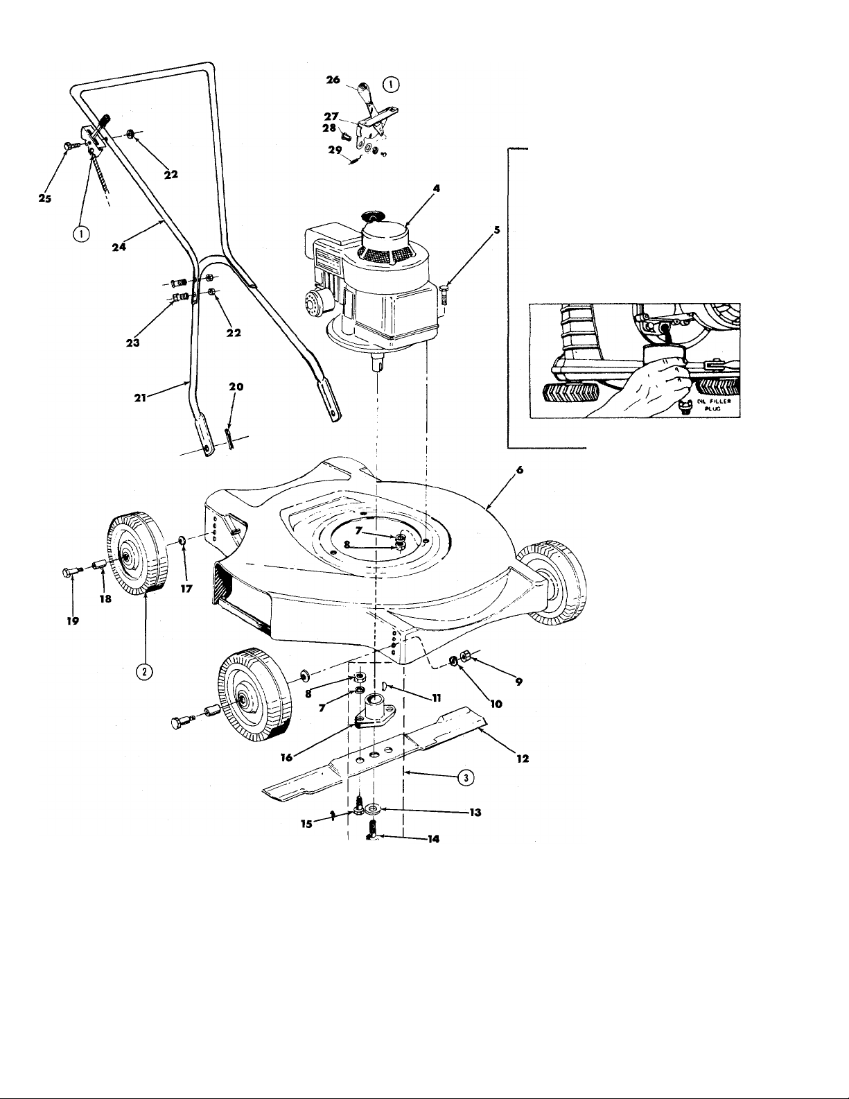
Page 3

PARTS LIST FOR M
Ref. Part
No. No.
OWER MODEL 111-200
DESCRIPTION
1
310-8842
2 504-9392
3 901-10769
4 —
5
6
710-158
370-10907
7 736-119
8 712-123
Throttle Control — Complete
Wheel Assembly — Complete
Blade Adapter Kit/Less Blade
English
Hex Head Cap Screw 5/16 — 24 x 1-1/4” Long*
Deck Assembly
Spring Lockwasher 5/16 Screw *t
Hex Nut 5/16-24 Thread *t
9 712-798 Hex Nut 3/8—16 Thread *
10
11 714-365
12 312-7582
13 736-217
14
15
16
736-217
710-459
710-117
748-189
Spring Lockwasher 3/8 Screw — Heavy Duty *f
Hi Pro Key #505 *t
Blade 20”
Spring Lockwasher 3/8 Screw — Heavy Duty *t
Hex Head Cap Screw 3/8-24 x 1-1/2” Long - Heat Treated t
Hex Head Cap Screw 5/16—24 x 1” Long — Heat Treated t
Blade Adapter t
17 736-105 Belleville Washer
18 305-7006
19
738-213 Axle Bolt
20 714-507
21 310-7036
22
712-107
Fortiflex Bearing
Cotter Pin
Lower Handle
Hex Locknut 1/4—20 Thread *
23 710-106 Hex Head Cap Screw 1/4—20 x 1-1/4” Long *
24 310-7585 Upper Handle
25 710-606 Hex Head Cap Screw 1/4—20 x 1-1/2” Long *
26
27
305-7470
Throttle Control — Knob i
310-8499 Throttle Control — Bracket $
28 901-7627 Ferrule Assembly t
29
732-141 Conduit and Wire t
30 746-145 Cable Clip (not shown)
* For faster service obtain standard nuts, bolts, and washers locally. If these items cannot be obtained
locally, order by part number and size as shown on parts list.
t Part of Blade Adapter Kit — Complete (901-10769)
t Part of Control Throttle Complete (310-8842)
If repairs or service is needed on the engine, please contact your nearest
authorized engine service outlet. Check the “Yellow Pages” of your
telephone bokk under “Engines — Gasoline.”
FORM NO. 770-3321C
Page 4

ASSEMBLY
Your new mower is shipped preassembled with the exception
of the handle
1. Remove lawn mower and all parts from the carton. Make
certain that all loose parts and literature have been
removed before the carton is discarded.
2. Extend throttle control assembly which is attached to
engine at the rear of the mower and place on the floor.
CAUTION: Do not bend or kink control wires.
3. Assemble the upper and lower handle parts with cap
screws and locknuts provided in parts bag. On mower
Model 111-200 use the longer (yellow) screw to attach
throttle control.
4. Holes at the bottom of the lower handle are to be fitted
over studs located in front of each rear wheel mounting
position.
5. Secure throttle control wire to lower right handle with
cable clips.
6. Check blade bolts for proper tightness.
OPERATION
For shipping purposes, the wheels on your mower are
generally set in the upper mounting holes. Relocating the
wheels to the second holes from the bottom will give
better mowing results in most cases. When changing wheel
positions, be sure Belleville washers are assembled
properly. (See cutting height instructions.)
1. Service engine with gas and oil. See engine manual packed
with lawn mower for complete instructions for the care and
maintenance of engine. READ DIRECTIONS CAREFULLY.
2. When ready to start engine, place throttle control lever on
handle in “START” position and start engine in accord
ance with instructions in engine manual. After engine
starts, move throttle control lever on handle to desired
engine speed. The engine is stopped by placing control
lever on handle in the “STOP” position.
3. Be sure that lawn is clear of stones, sticks, wire or
other objects which could damage lawn mower or engine.
For best results and to insure more even grass distribu
tion, do not mow when lawn is excessively wet.
ADJUSTMENTS
CAUTION: Do not at any time make any adjustment to lawn
mower without first stopping engine and disconnecting spark
plug wire.
CUTTING HEIGHT
Adjustment may be made by removing and moving wheel studs
to desired position. Cutting heights will be raised as wheel
studs are moved to a lower hole and lowered as wheel studs
are moved to a higher hole in the deck. All wheel studs must
be mounted in a relative position to the deck.
THROTTLE
If adjustment becomes necessary, the throttle control wire
assembly can be reset as follows:
1. Loosen, but do not remove, screw securing throttle control
wire assembly at engine.
2. Move throttle control lever on handle to “FAST” position.
3. Move lever, to which control wire is fastened at engine.
To full open position and retighten screw to secure throttle
control wire assembly.
LUBRICATION
IMPORTANT: Always stop engine and disconnect spark plug
wire before cleaning, lubricating or doing any kind of work
on lawn mower.
WHEELS - Wheel bearings are of lifetime Fortiflex. They
require no lubrication.
THROTTLE - Periodically lubricate throttle control lever
and throttle wire assembly with a few drops of light oil
(S.A.E. No. 10 or 20) for ease of operation.
ENGINE - Follow engine manual for lubrication instructions.
MAINTENANCE
CUTTING BLADE: The blade may easily be removed for
grinding or replacement as follows:
1. Remove bolt and lock washer holding blade and hub
assembly to engine crankshaft.
2. Remove blade and hub assembly from engine crankshaft.
3. Remove two bolts, lock washers and nuts holding blade
to blade hub.
When sharpening blade, follow the original angle of grind as
a guide. It is extremely important that each cutting edge
receives an equal amount ofgrindingto preventan unbalanced
blade. An unbalanced blaide will cause excessive vibration
when rotating at high speeds and may cause damage to
the mower.
Upon reassembly, make certain all parts are assembled
properly and tightened securely.
DECK - The underside of mower deck should be cleaned
after each period of use as grass clippings, leaves, dirt and
other matter will accumulate. This accumulation of grass
clippings, etc., is undesirable as it will invite rust and
corrosion and may cause an uneven discharge of grass
clippings at the next cutting.
The deck may be cleaned by tilting the mower forward or On
its left side and scraping clean with a suitable tool or by
washingwith a stream of water froma gardenhose. CAUTION:
Do not direct the stream of water at a hot engine as damage
to the engine may result.
STORAGE - The following steps should be taken to prepare
lawn mower for storage.
1. Clean and lubricate mower thoroughly as described in
the preceding instructions.
2. Refer to engine manual for correct engine storage
instructions.
3. Coat mower’s cutting bladewith chassis grease to prevent
rustin g.
4. Place blocks under deck to raise tires clear of floor.
5. Store mower in a dry, clean area.
USING YOUR ROTARY MOWER
For the best results do not cut wet grass because it tends to
stick to the underside of the mower, thus preventing proper
discharge of grass clippings. If wet grass must be cut, reduce
engine speed and walking speed to help distribute the clip
pings more effectively.
New grass should be treated as wet grass, otherwise a normal
walking speed is about the right pace for efficient mowing.
The best mowing pattern is one that allows the clippings to
discharge towards the uncut part of the lawn. This permits
recutting of the clippings to further pulverize them. When
cutting high weeds, discharge towards cut portion then recut
at right angles to first direction.
Lawn should be cut in the fall as long as there is growth.
FORM NO. 770-3321D
PRINTED IN U.f.A.
 Loading...