

Page 1

OWNEirSGUM
ASSEMBLY • OPERATION • MAINTENANCE • PARTS
20" and 22"
ROTARY
$1.00
MOWERS
Model Series
111-070R000 thru 111-078R000
111-080R000 thru 111-089R000
111-200R000 thru 111-206R000
111-220R000 thru 111-226R000
(Models 072R and 082R Shown)
Important: Read Safety Rules and Instructions Carefully
WARNING: This unit is equipped with an internal combustion engine and should not be used
on or near any unimproved forest-covered, brush-covered or grass-covered land unless the
engine’s exhaust system is equipped with a spark arrester meeting applicable local or state
laws (if any). If a spark arrester is used, it should be maintained in effective working order
by the operator.
In the State of California the above is required by law (Section 4442 of the California Public
Resources Code). Other states may have similar laws. Federal laws apply on federal lands.
in
AMERICA
A spark arrester for the muffler is available through your nearest engine authorized service
dealer or contact the service department, P.O. Box 360900, Cleveland, Ohio 44136.
SOPFLEMeJir SHEET /*A!ISÙ
n0'ûgi.-ûûû
PRINTED IN U.S.A.
FORM NO. 770-7500F
Page 2

IMPORTANT
THIS SYMBOL POINTS OUT IMPORTANT SAFETY INSTR JCTIONS WHICH, IF NOT FOLLOWED, COULD ENDANGER THE PERSONAL SAFETY
AND/OR PROPERTY OF YOURSELF AND OTHERS. READ AND FOLLOW ALL INSTRUCTIONS IN THIS MANUAL BEFORE ATTEMPTING
A
TO OPERATE YOUR LAWN MOWER. FAILURE TO CON PLY WITH THESE INSTRUCTIONS MAY RESULT IN PERSONAL INJURY. WHEN,
YOU SEE THIS SYMBOL- A HEED ITS WARMING.
RULES FOR SAFE OPERATION
A
DANGER: with any type of power equ ipment, carelessness or error on the part of the operator can result In serious
Your lawn mower was bull I to be operated according to the rules for safe operation In this manual. As
A
TRAINING
1. Read this owner’s guide carefully In Its entirety before attempting
A-
to assemble or operate this machine. Be completely f< miliar with
the controls and the proper use of this machine befoni operating
it. Keep this manual in a safe place for future and reguL r reference
and for ordering replacement parts.
2. Your rotary mower is a precision piece of power equi iment, not
a plaything. Therefore, exercise extreme caution at all 1 mes. Your
unit has been designed to perform one job: to mow grass. Do
not use it for any other purpose.
3. Never allow children under 14 years old to operate a po\ ler mower.
Children 14 years old and over should only operate mi iwer under
close parental supervision. Only persons well acquaintec with these
rules of safe operation should be allowed to use yoi ir mower.
4. Keep the area of operation clear of all persons, particularly small
children and pets. Stop engine when they are in the vicinity of
your mower to help prevent blade contact or throwr object in
jury. Although the area of operation should be complel ely cleared
of foreign objects, an object may have been overlook» and could
be accidently thrown by the mower in any direction and cause
serious personal injury to the operator or any others allowed in
the area.
PREPARATION
Thoroughly inspect the area where the equipment is lo be used.
Remove all stones, sticks, wire, bones and other fore gn objects
which could be picked up and thrown by the mower ir any direc
tion and cause serious personal injuiy to the operator oi any others
allowed in the area. Plan your mowing pattern to avok discharge
of material toward roads, sidewalks, bystanders and the like.
2. Always wear safety glasses or eye shields during operat on or while
performing an adjustment or repair, to protect eyes frDm foreign
objects that may be thrown from the machine in am direction.
3. Wear sturdy, rough-soled work shoes and close-fitting slacks and
shirts. Shirts and pants that cover the arms and legs and steel
toed shoes are recommended. Do not wear loose fitt ng clothes
or jewelry. They can be caught in moving parts. Nei er operate
a unit in bare feet, sandals, or sneakers.
4. Before working with gasoline, extinguish all cigarettes, c gars, pipes
and other sources of ignition. Check the fuel level before starting
the engine. Gasoline is an extremely flammable fuel. Do not fill
the gasoline tank Indoors, while the engine, is running, or until
engine has been allowed to cool for at least two mi lutes after
running. Replace gasoline cap securely and wipe off any spilled
gasoline before starting the engine as it may causî a fire or
explosion.
5. Disengage the self-propelled mechanism or drive dut ;h on units
so equipped before starting the engine.
6. The blade control handle is a safety device. Never attemi t to bypass
its operation. Doing so makes the safety device inop jrative and
may result in personal injury through contact with 1 ie rotating
blade. The blade control handle must operate easily in both direc
tions and automatically return to the disengaged pos:ition when
released.
7. Never attempt to make a wheel or cutting height adjus ment while
the engine is running.
8. Never operate the mower in wet grass. Always be s ire of your
footing. A slip and fall can cause serious personal injury. Keep
a firm hold on the handle and walk, never run. Mow onl; ' in daylight
or in good artificial light.
injury. If you violate any o’ these rules, you may cause serious injury to yourself or others.
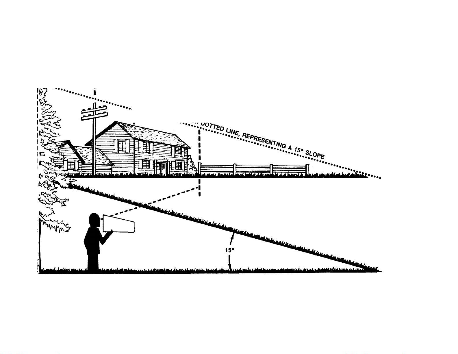
For your safety, use the slope gauge included as part of this manual
to measure slopes before operating this unit on a sloped or hilly
area. If the slope is greater than 15° as shown on the slope gauge,
do not operate this unit on that area or serious injury could result.
OPERATION
Do not change the engine governor settings or overspeed the
engine. Excessive engine speeds are dangerous.
2.
Do not put hands or feet near or under rotating parts. Keep clear
of the discharge opening at all times as the rotating blade can
cause injury.
Stop the blade when crossing gravel drives, walks or roads.
After striking a foreign object, stop the engine, remove the wire
from the spark plug, and thoroughly inspect the mower for any
damage. Repair the damage before restarting and operating the
mower.
5.
If the equipment should start to vibrate abnormally, stop the engine
and check immediately for the cause. Vibration is generally a warn
ing of trouble.
Shut the engine off and wait until the blade comes to a complete
stop before removing the grass catcher or unclogging the chuteThe cutting blade continues to rotate for a few seconds after
engine is shut off. Never place any part of the body in the bk
area until you are sure the blade has stopped rotating.
7.
Before cleaning, repairing or inspecting, make certain the blade
and all moving parts have stopped. Disconnect the spark plug wire,
and keep the wire away from the spark plug to prevent accidental
starting.
Do not run the engine indoors.
Never cut grass by pulling mower toward you. Mow across the
face of slopes, never up-and-down. Exercise extreme caution when
changing direction on slopes. Do not mow excessively steep slopes.
Always be sure of your footing. A slip and fali can cause serious
personal injury.
10.
Never operate mower without proper guards, plates or other safety
protective devices in place.
11.
Muffler and engine become hot and can cause a burn. Do not
touch.
MAINTENANCE AND STORAGE
Check the blade and engine mounting bolts at frequent intervals
for proper tightness. Also visually inspect blade for damage (e.g.
bent, cracked). Replace with blade which meets original equip
ment specifications.
Keep all nuts, bolts, and screws tight to be sure the equipment
is in safe working condition.
Never store the mower with gasoline in the tank or gas containers
inside of a building where fumes may reach an opan flame or spark
(e.g. gas hot water heater). Allow the engine to cool before stor
ing In any enclosure.
To reduce fire hazard, keep the engine free of grass, leaves and
excessive oil.
Check the grass catcher bag frequently for wear or détériorât
Replace a worn or damaged bag immediately. For safety prott.
tion, replace only with new bag meeting original equipment
specifications.
Page 3
--------
j------------------------------------------------------------------------------------------------------------------OUT Mio jns Line-------------------------------------------------------------------------------------------------------------------------- I
USE THIS SHEET AS A GUIDE TO DETERMINE SLOPES WHERE YOU MAY NOT OPERATE SAFELY.
SIGHT AND HOLD THIS LEVEL WITH A VERTICAL TREE
----------------------
----------------
^---------------------------------A CORNER OF A BUILDING
I
..........
A POWER POLE
.
OR A FENCE POST
T3
o
o
0)
CO
0)
zr
(D
(D
S'
CD
(0
w
■D
(D
O
D
O
(D
C
n
C
-t
(D
“T
(D
(D
(D
3
o
0
WARNING
AC
Do not mow on inclines with a slope in excess of IS degrees (a rise of approximately 2V2 feet every 10 feet). A
riding mower could overturn and cause serious injury. If operating a waik-behind mower on such a slope, it is
extremely difficult to maintain your footing and you could slip, resulting in serious injury.
Operate RIDING mowers up and down slopes, never across the face of slopes.
Operate WALK-BEHIND mowers across the face of slopes, never up and down slopes.
Page 4
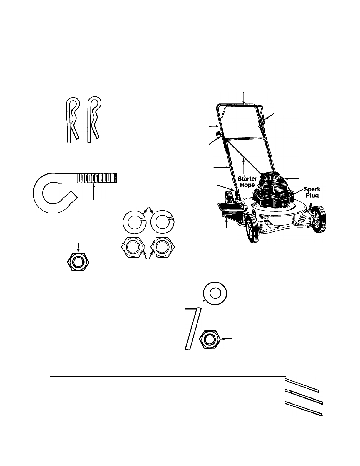
CONTENTS OF HARDWARE PACK
Remove this sheet from your owner’s manual £ nd lay the hardware on the illustration for identification purposes.
After assembly, keep the Slope Gauge which is on the reverse side of this sheet for future use.
(Hardware pack may contain extra items which are not used on your unit—
Part numbeis are shown in parentheses.)
ATTACHING THE
LOWER HANDLE
Hairpin—«
Clips
(714-0104)
ATTACHING THE
STARTER ROPE
Rope Guide
(710-1205)
Hex Lock Nut
V4-2O Thread
(712-0324)
ATTACHING THE CABLE BRACKET AI>1D
(OPTIONAL) THROTTLE CONTROL Spring Washer
R ATTACHING THE
UPPER H I^NDLE
Curved
Head Be lts
(710-06/1)
Split Was hers
5/16" I D.
(736-0119)
Hex Nuts
5/16-18 Tliread
(712-021)7)
1/4" I.D.
Cable ^ (736-0175)
Bracket
(17174)
\
O
Upper-
Handle
Rope
Guide
Lower
Handle
Handle
Mounting
Brackets
Blade Control
Handle
Chute
Deflector
(Models 072R and
082R Shown)
PARTS IDENTIFICATION
Hex Nut
Vt-20 Thread
(712-0287)
Throttle
Control
(Optional)
Engine
\ Hex Bolt
V4-20 X 1-7/8" Long
(710-1216)
1-----Hex Bolt
1/4-20 X 1" Long
(710-0597)
(Used With No
Remote Throttle)
O
c
>
—1
3"
«■
I-
5'
(D
SECURING THE CABLES
n
n
n
I > 111111111111111111111
0
INCHES
LI
U
If
Cable Ties
(726-0240)
f
Page 5
ASSEMBLY INSTRUCTIONS
This owner’s guide covers various modeis of
mowers. Foiiow only those instructions which per
tain to your unit.
IMPORTANT: This unit is shipped WITHOUT
GASOLINE or OIL. After assembly, service engine
with gasoline and oil as instructed in the separate
engine manual packed with your unit.
NOTE: Reference to right or left hand side of the
mower is observed from the operating position.
Tools Required for Assembly
(1) Pair of Pliers
(1) 1/2" Wrench*
(2) 7/16" Wrenches*
*Or two 6" Adjustable Wrenches
Lower
Handle
Handle
Mounting
Bracket
Hairpin
Clip
FIGURE 1.
Hole in Blade
Control Handle
UNPACKING
1. Remove the lawn mower from the carton by open
ing the top flaps and lifting the unit out. Be careful
of the staples. Make certain all parts and literature
have been removed from the carton before the car
ton is discarded.
2. Disconnect the spark plug wire and move away
from the spark plug.
Stretch out all control cables and place on the floor.
3.
Be careful not to bend or kink the cables at any
time during assembly.
4.
Remove page four from this manual and lay the
contents of the hardware pack on the illustration
for identification.
AHACHING THE LOWER HANDLE (Hardware A)
1. Attach the lower handle by placing the bottom
holes in the lower handle over the weld pins on the
handle mounting brackets extending through the
rear of the deck.
Using a pair of pliers, squeeze one leg of the lower
handle against the handle mounting bracket. In
sert the hairpin clip into the inner hole on the weld
pin. See figure 1. Repeat on other side.
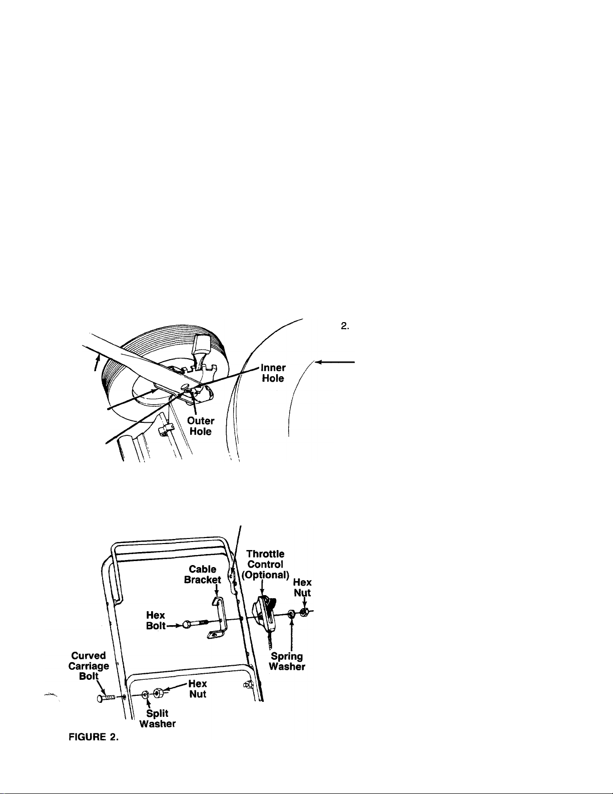
NOTE: There are two (2) holes in the handle mounting
brackets. Place the hairpin clip in the inner hole for
operation. Outer hole is for storage.
ATTACHING THE UPPER HANDLE (Hardware B)
1. Place the upper handle in position over the lower
handle. The hole in the side of the blade control
handle (attached to the upper handle) must be on
the left side.
2. Secure the upper handle to the lower handle us
ing the curved head bolts, split washers and hex
nuts as shown in figure 2.
AHACHING THE CABLE BRACKET AND THRDTTLE CDNTRDL (Hardware D) (Dptional)
If your mower is equipped with a remote throttle con
trol, it is already attached to the engine. Attach the
cable bracket and throttle control to the left side of up
per handle as follows. See figure 2.
NOTE: If your mower does not have a remote throttle
control, attach the cable bracket using the 1" long hex
bolt provided and following steps 2 and 4 only.
1. Route the throttle control cable inside the handle
mounting bracket and beneath the lower handle.
2.
Place cable bracket against left side of upper han
dle, lining up the hole in the bracket with the bot
tom hole in upper handle. Place 1/4" hex bolt
through cable bracket and handle, from the inside
to the outside.
3.
Place throttle control on the hex bolt (outside of
the upper handle), with the throttle lever facing
upward.
Page 6

“Z”
FIGURE 3.
\\ ) ‘V
Hole in
Bracket
Plastic Fitting
-Blade
Control
Handle
4. Secure with spring washer (cupped side against
the throttie control) and hex nut.
ATTACHING THE BRAKE CABLE
1. The brake cable is attached to the engine, and has
a “Z” fitting on the loose end. Route the brake
cable below the lower handle. Place end of cable
through the hole in the bracket as shown in figure
-3. Push the plastic fitting until it locks into the hole
in the bracket.
WARNING: Brake cable must be assem
bled as shown for proper blade brake
A
2. Hook the “Z” end of the brake cable into the hole
operation.
in the blade control handle from the inside to the
outside as shown in figure 3.
SECURING THE CABLES (Hardware E)
Secure all cables to the left side of the handle as
follows.
1. Insert posts on cable ties into holes provided on
the handles, one on the upper handle and two on
the lower handle. The holes may be either on the
inside or outside of the handles. See figure 4A.
2. Secure the cables with the cable ties. See figure
-------
4B.
3. Trim excess ends of cable ties.
FIGURE 5.
FIGURE 6.—Optional Hub Caps
ATTACHING THE STARTER ROPE (Hardware C)
1. The starter rope is inside the top of the engine. Ad
ditional rope may be wound around the starter han
dle. If so, unwind the rope from the handle.
2. With the spark plug wire disconnected and
grounded, depress the blade control handle and
pull the rope out of the engine.
—3. Place the rope guide around the starter handle, so
the rope guide is positioned as shown (bends
downward slightly). Insert the rope guide through
the side of the upper handle, and secure with hex
lock nut.
INSTALLATION OF HUB CAPS (Optional)
1. If your mower is equipped with hub caps which
have four tabs, line up the tabs on the hub caps
with the holes in the wheels. Push to lock in
position.
2. If your mower is equipped with 2" wide tires, place
hub caps in position against the inner hub of the
wheel. Press firmly around the center portion of
hub cap in a circular motion, similar to installing
-------
a lid on a round, plastic container. See figure 6.
The hub caps are flexible and will snap over the
3V2" diameter wheel hubs.
NOTE: It may be helpful to place the hub caps In hot
tap water for several minutes to make them pliable
before installing, especially if the temperature is less
than 60°F.
Page 7

FINAL ASSEMBLY OF MOWER
1. The chute deflector on your mower is held in an
upright position by a block for shipping purposes
only. This shipping block must be removed and
discarded before the mower is put into operation.
-------
See figure 7.
To remove the shipping block, move the spring-
loaded chute toward the engine by pushing above
the shipping block. Remove the block and carefully
lower the chute into operating position, keeping
fingers out of the way.
2. Make certain all nuts and bolts are tightened
securely.
BLADE CONTROL HANDLE
WARNING: This control mechanism is a
safety device. Never attempt to bypass its
A
operations.
CONTROLS
The blade control handle is located on the upper han
dle of the mower. See figure 8. The biade control han
dle must be depressed in order to operate the unit.
Release the blade control handle to stop the engine and
blade.
A
THROTTLE CONTROL (Optional)
The throttle control is located on the side of the upper
handie or on the engine. It is used to regulate the
engine speed.
A
RECOIL STARTER
The recoii starter handle is attached to the handle. See
figure 8. Stand behind the unit in the operating posi
tion to start the unit.
WARNING: The blade will be rotating
whenever the engine is running.
WARNING: The throttle control cannot be
used to stop the engine.
Page 8

OPERATION
TO REDUCE THE RISK OF INJURY, DO NOT
OPERATE MOWER UNLESS REAR TRAILING
SHIELD AND THIS GUARD OR ENTIRE
GRASS CATCHER IS IN ITS PROPER PLACE.
FIGURE 9.
Keep hands and feet away from the chute area on
cutting deck. See figure 9.
The operation of any lawn mower can result in
foreign objects being thrown into the eyes, which
can result in severe eye dainage.
Always wear safety glasses nr eye
shields. We recommend wide vision
safety mask for over spectacles or
standard safety glasses.
Metal Loop
on Spark
Plug Wire
Rubber Boot
FIGURE 10.
2. Open fuel shut-off valve if so equipped. Refer to
the separate engine manual.
3. Move throttle control lever all the way forward.
4. Tecumseh engines only: Prime engine as in
structed in the separate engine manual.
5. Standing behind the unit, depress the blade con
trol handle and hold it against the upper handle
as shown. See figure 11.
6. Grasp the recoil starter handle and pull back rapid
ly, extending rope fully. Return it slowly to the rope
guide bolt.
7. After engine starts, move throttle control to desired
engine speed.
NOTE: if any probiems are encountered, refer to the
Troubie Shooting Guide on page 16.
NOTE: For shipping purposes your mower is set with
the wheeis in a iow cutting height position. For best
resuits raise the cutting position untii it is determined
which height is best for your iawn. See cutting 'leight
adjustment section.
GAS AND OIL FILL-UP
Service the engine with gasoiine and oii as instructed
in the separate engine manual packed with your
mower. Read instructions carefully.
WARNING: Never fill fuel tank indoors,
with engine running or until the engii le has
A
been allowed to cool for at least two
minutes after running.
TO START ENGINE AND ENGAGE BLADE
1. Attach spark plug wire to spark plug. If jnit is
equipped with a rubber boot over the end of the
spark plug wire, make certain the metal loop on
the end of the spark plug wire (inside the ubber
boot) is fastened securely over the metal tip on the
spark plug. See figure 10.
FIGURE 11.
TO STOP ENGINE AND BLADE
1. Release the blade control handle to stop the
engine and blade.
WARNING: The blade continues to rotate
for a few seconds after the engine is shut
A
2. Disconnect the spark plug wire and ground it
off.
against the engine to prevent accidental starting
while equipment is unattended.
Page 9

USING YOUR ROTARY MOWER
Be sure that lawn is clear of stones, sticks, wire, or other
objects which could damage lawn mower or engine.
Such objects could be accidently thrown by the mower
in any direction and cause serious personal injury to
the operator and others.
For the best results, do not cut wet grass because it
tends to stick to the underside of the mower, prevent
ing proper discharge of grass clippings, and could
cause you to slip and fall. New grass, thick grass or
wet grass may require a narrower cut. Blade speed
should be adjusted to the condition of the lawn.
The best mowing pattern is one that allows the clippings
to discharge towards the uncut part of the lawn. This
permits recutting of the clippings to further pulverize
them. When cutting high weeds, discharge towards cut
portion, then recut at right angles to first direction.
For best results, cut off one-third or less of the total
length of the grass. Lawn should be cut in the fall as
long as there is growth.
This mower is designed to be operated at full throttle
to give you the best cut and do the most effective job
of bagging the cut grass.
WARNING: If you strike a foreign object,
stop the engine. Remove wire from spark
A
plug, thoroughly inspect the mower for any
damage, and repair the damage before
restarting and operating the mower. Exten
sive vibration of the mower during opera
tion is an indication of damage. The unit
should be promptly inspected and
repaired.
FIGURE 12.
THROTTLE CONTROL ADJUSTMENT
If the throttle control (optional) needs adjustment or if
it has been replaced, adjust as follows.
Briggs & Stratton Quantum Engi.ies:
1. Remove the screw shown in figure 13. Remove the
cable clamp from the cable.
2. Push the throttle control lever on the handle all the
way forward to CHOKE position. Make certain the
throttle control lever remains in this position.
3. Push the control lever on the engine as far toward
the rear of the engine as it will go. Secure the cable
in this position with the cable clamp and screw.
Cable
Clamp
ADJUSTMENTS
WARNING: Do not at any time make any
adjustment to lawn mower without first
A
CUTTING HEIGHT ADJUSTMENT
An adjusting plate and thumb lever at each wheel posi
tion provides cutting height adjustment. Each adjusting
plate has nine height positions. Height of cut will be
changed when the thumb lever is moved from one hole
to another. Simply depress the lever towards wheel and
move wheel and lever assembly to desired position. All
wheels must be placed in the same relative position.
See figure 12.
stopping engine and disconnecting spark
plug wire.
FIGURE 13.—Briggs & Strattoh Quantum Engines
Briggs & Stratton Standard and Sprint Engines
and all Tecumseh Engines (all other models):
1. Loosen (do not remove) the screw on the cable
clamp so that the cable will move freely under the
clamp. See figure 14.
2. Place the throttle control lever on the handle all the
way forward to START position.
3. Place the control lever on the engine in the full
open position by pushing it as far toward the out
side (Briggs and Stratton engine) or rear
(Tecumseh engine) of the engine as it will go.
Tighten the screw on the cable clamp to secure
the cable in this position.
Page 10

Control
Lever
On Engine
FIGURE 14A.—Briggs & Stratton Standard Engine
Blade Control—Lubricate the pivot points on the blade
control handle and the brake cable at least once a
season with light oil. See figure 15. The blade control
must operate freely in both directions.
Chute Deflector—The torsion spring and pivot point
should be lubricated periodically with light oil to pre
vent any rust or binding. Deflector must work freely.
Wheels—Mower may be provided with ball bearing
wheels. Lubricate at least once a season with light oil.
Also, if the wheels are removed for any reason,
lubricate the surface of the axle bolt and the inner sur
face of the wheel with light oil. A 4 oz. plastic bottle
of light oil lubricant is available. Order part number
737-0170. Engine oil may also be used.
Engine—Follow engine manual for lubrication in
structions.
Throttle—Periodically lubricate throttle control lever
and throttle wire assembly with a few drops of light oil
for ease of operation.
FIGURE 14B.—Tecumseh Engines
CARBURETOR ADJUSTMENTS
WARNING: If any adjustments are made to
the engine whiie the engine is running (e.g.
A
Minor carburetor adjustments may be requ red to
compensate for differences in fuel, tempe ature,
altitude and load. To adjust carburetor, refer to the
separate engine manual packed with your mcwer.
NOTE: A dirty air cleaner will cause an engine to run
rough. Be certain air cleaner is clean and attached to
the carburetor before adjusting carburetor. Refer to the
separate engine manual.
carburetor), keep ciear of ali moving parts.
Be carefui of heated surfaces and nr uffier.
LUBRICATION
WARNING: Always stop engine and
disconnect spark plug wire before clean
A
ing, iubricating or doing any kind of work
on lawn mower.
MAINTENANCE
WARNING: Be sure to disconnect and
ground the spark plug wire before perform-
Ai
iing any repairs or maintenance.
NOTE: When tipping the unit, empty the fuel tank and
keep engine spark plug side up.
TROUBLE SHOOTING
Refer to page 16 of this manual for trouble shooting
information.
CUTTING BLADE
When removing the cutting blade for sharpening or
replacement, protect hands by using heavy gloves or
a rag to grasp the cutting blade. Remove the bolt and
bell washer which hold the blade and adapter to the
engine crankshaft. Remove the blade and adapter from
the crankshaft.
If the blade or blade adapter needs replacing, remove
the two small bolts, lock washers and nuts which hold
the blade to the adapter.
WARNING: Periodically inspect the blade
adapter for cracks, especially if you strike
A
a foreign object. Replace when necessary.
10
Page 11

When sharpening the blade, follow the original angle
of grind as a guide. It is extremely important that each
cutting edge receives an equal amount of grinding to
prevent an unbalanced blade. An unbalanced blade will
cause excessive vibration when rotating at high speeds,
may cause damage to the mower and could break,
causing personal injury.
It is recommended that the blade always be removed
from the adapter for the best test of balance.
The blade can be tested by balancing it on a round shaft
screwdriver. Remove metal from the heavy side until
it balances evenly.
Before reassembling the blade and the blade adapter
to the unit, lubricate the engine crankshaft and the inner
surface of the blade adapter with light oil. Lubricating
the bolt holes, bolts and inner surface of the nuts with
light oil is also recommended. A 4 oz. plastic bottle of
light oil lubricant is available. Order part number
737-0170. Engine oil may also be used.
When replacing the blade, be sure to install the blade
with the side of the blade marked “Bottom” (or with
part number) facing the ground when the mower is in
the operating position.
Blade Mounting Torque
Center Bolt and Blade Adapter Bolts:
375 in. lb. min., 450 in. lb. max.
To insure safe operation of your unit, all nuts and bolts
must be checked periodically for correct tightness.
DECK
The underside of the mower deck should be cleaned
after each use to prevent a buildup of grass clippings,
leaves, dirt or other matter. If this debris is allowed to
accumulate, it will invite rust and corrosion, and may
cause an uneven discharge of grass clippings at the
next cutting.
The deck may be cleaned by tilting the mower and
scraping clean with a suitable tool (make certain the
spark plug wire is disconnected).
ENGINE
Refer to the separate engine manual for engine
maintenance instructions.
Maintain engine oil as instructed in the separate
engine manual packed with your unit. Read and follow
instructions carefully.
Service air cleaner every 25 hours under normal con
ditions. Clean every few hours under extremely dusty
conditions. Poor engine performance and flooding
usually indicates that the air cleaner should be ser
viced. To service the air cleaner, refer to the separate
engine manual packed with your unit.
The spark plug should be cleaned and the gap reset
once a season. Spark plug replacement is recom
mended at the start of each mowing season; check
engine manual for correct plug type and gap
specifications.
Clean the engine regularly with a cloth or brush. Keep
the cooling system (blower housing area) clean to per
mit proper air circulation which is essential to engine
performance and life. Be certain to remove all grass,
dirt and combustible debris from muffler area.
OFF-SEASON STORAGE"
The following steps should be takfin to prepare lawn
mower for storage.
1. Clean and lubricate mower thoroughly as de
scribed in the lubrication instructions.
2. Refer to engine manual for correct engine storage
instructions.
3. Coat mower’s cutting blade with chassis grease
to prevent rusting.
4. Store mower in a dry, clean area.
NOTE: When storing any type of power equipment in
an unventilated or metal storage shed, care should be
taken to rust-proof the equipment. Using a light oil or
silicone, coat the equipment, especially cables and all
moving parts.
HANDLE STORAGE
The handle may be placed in an upright position for
storage. Move hairpin clips to outer hole on weld pins.
See figure 1. Press inward on the bottom of the lower
handle and push forward. The handle will lock In this
position.
To place the handle in the operating position, remove
the starter rope from the rope guide bolt. Grasp the
lower handle at the bottom, press inward slightly and
tip the handle backward. Place the hairpin clips in the
inner holes. With the spark plug wire disconnected and
grounded, depress the blade control handle and pull
the starter rope out from the engine. Slip the starter
rope into the rope guide bolt.
NOTE: The use of any accessory on this Rotary Mower other than those manufactured by the mower manufacturer is
not recommended. GRASS CATCHER Model 086 is available as optional equipment for the mowers shown in this manual.
WARNING: To reduce the risk of injury, do not operate mower unless rear trailing shield and guard or
A
NOTE: Under normal usage bag material is subject to wear and should be checked periodically. Be sure any replace
ment bag complies with the mower manufacturer’s recommendations. For replacement bags, use only factory authorized
replacement bag No. 764-0271.
entire grass catcher is in its proper place.
11
Page 12

Models 070R thru 089R
‘For faster service obtain standard nuts, bolts and washers locally.
If these items cannot be obtained locally, order by part number and
size as shown on parts list.
CODE: N notates a new part (not previously existing). A three digit
number is the color code. Specify color code if color or finish is
important when ordering parts as shown below, [i.e., 638 for Red
^ Finish].
Color Codes
456—Radiant Tangerine 629—Silver Flake
460—Green Flake
483—Charcoal Gray
498—Yellow
499—Beige 640—Green
621—Brilliant Fire Mist 646—CM Blue
630—Metallic Blue
637—Black
638—Red
NOTE; The engine is not under warranty by
the mower manufacturer.. .If repairs or
service is needed on the engine, please
contact your nearest author
ized engine service outlet.
Check the ‘‘Yellow Pages” of
your telephone book under
‘‘Engines—Gasoline.”
Find It Fast
In The
Yellow Pages
Optional Hub Caps
Description Part No.
Gray (for “S” Wave Wheels)
Beige (for ”S” Wave Wheels)
Red (with 4 tabs)
Black (with 4 tabs)
12
731-0981A
731-0982A
731-0124
731-0354
^30
^30
Page 13

PARTS LIST FOR MODELS 070R THRU 089R ROTARY MOWERS
1
PART
NO.
747-0748
CODE DESCRIPTION
Control Handle Ass’y- (Std.)
731-1135 Control Handle Ass’y. w/PlastIc
2
736-0270 Bell-Wash. Va" I.D.
3 17174
Cable Brkt.
4 710-1216 N Hex Bolt 1/4-20 X 1.875" Lg.*
710-0597
Hex Bolt 1/4-20 X 1" Lg.* 47
REF.
NO.
41 710-0429
42 751-0369
43
44 735-0639
46
(Used without Throttle Control) 48
5 736-0175 Spr. Wash. 1/4" I.D. 49 14832
712-0287
6
749-0756A
8
Hex Nut 1/4-20 Thd.*
Upper Handle 51 15261A
N
Rope Guide
50 15262B Pivot Bar
52
L-Wash. 5/16" I.D.* 53 14578
712-0267
710-0671
Hex Nut 5/16-18 Thd.* R.F. & L.R.
Curved Carriage Bolt 5/16-18
X 1.38" Lg.
726-0240 Cable Tie 54
749-0372B
Lower Handle
Hairpin Cotter 746-0820
17098
Hinge Clip
731-0872 Rear Flap
17189 Handle Bracket Ass’y.—L.H.
17188
Handle Bracket Ass’y.—R.H. 079R)
Bell-Wash. .39" I.D. x 1.38"
Hex Nut 3/8-16 Thd.*
L-Wash. 3/8" I.D.* 746-0832
712-0241
17036 638 20" Deck Ass’y.
Hex Nut 3/8-24 Thd.*
55 746-0553.
17046 638 22" Deck Ass’y.
Blade Adapter Kit (Keyed)
753-0485
Blade Adapter Kit (Splined) 746-0550
Bell-Wash. .39" I.D. (Used
w/Keyed Adapter) 746-0557
736-0453
Bell-Wash. .46" I.D. (Used
w/Splined Adapter) 746-0552
Hex Bolt 3/8-24 x 1.5" Lg.
(Used w/Keyed Adapter)
710-0757
Hex Bolt 7/16-20 X 1.5" Lg. 57 710-0654A
(Used w/Splined Adapter)
20" Blade 60 731-1034
742-0522
22" Blade 61
Hex L-Nut 1/4-20 Thd. 62 17032
12894A
__
Cable Clampt
Engine
63 747-0710
64
Iref.
■So.
10 747-1205
11 736-0119
12
13
14
15
16 714-0104
17
18
19
20
21 736-0356
22 712-0798
26 710-1055 Hex Bolt 3/8-24 x 1" Lg.*
27 736-0169
28
. 29
jO 753-0484
31 736-0452
32 710-1044
33 742-0520
37 712-0324
38
39
PART
NO.
CODE
DESCRIPTION
Hex B-Tap Scr. #10 x .38"t
Cable Clampt
710-0227
*■ *
736-0105
738-0507B
Hex AB-Tap Scr. #8 x .38"t
Spark Plug Boot (Optional)
Axle Bolt
Bell-Wash. .400" I.D. x .88"
ShId. Bolt .50" Dia. x .357"
Spring Lever Ass’y. w/Knob
* *
Height Adj. Plate
Wheel Ass’y. Comp.
Height Adi. Ass’y. Comp.—
14579 Height Adj. Ass’y. Comp.—
L.F. & R.R.
746-0801
Throttle Control Ass’y. Comp.—
51.62"t
Throttle Cofitrol Ass’y. Comp.—
49.62"tt
746-0830
Throttle Control Ass’y. Comp.—
38.62" (071R, 073R, 075R,
746-0831
Throttle Control Ass’y. Comp.—
41.62" (081R, 083R, 085R,
089R)
Throttle Control Ass’y. Comp.—
45.62" (077R, 087R)
Control Cable—36" (070R,
072R, 074R, 076R, 078R,
084R, 086R, 088R)
Control Cable—39"
(080R, 082R)
Control Cable—47"
(077R, 087R)
Control Cable—49" (071R,
073R, 075R, 079R, 081R,
083R, 085R, 089R)
Hex L-Wash. Hd. Scr.
3/8-16 X 1.0" Lg.
Chute Deflector Ass’y.
732-0593
Torsion Spring
Adapter Plate
Hinge Pin
710-0599
Hex Self-Tap Scr. V4-20 x .5" Lg.
tModels 070R, 072R, 080R & 082R Only
ttModels 074R, 076R, 078R, 084R, 086R & 088R Only
•WHEEL CHART
Wheels w/o Bearings Wheels With Bearings
Tread*** Ass’y. Comp. Axle Bolt Tread*** Ass’y. Comp. Bearings
•
Waffle
Rib
Bar
734-1162A (8")
734-1161A (7")
734-1169 (8")
734-1170 (7")
734-1608 (8")
738-0102
738-0102 Waffle
738-0144
738-0144
738-0102 “S” Wave 734-1513A Ball Brg. Va" I.D.-741-0180 (2 per Wheel)
•Tread Type: Waffle |
“T” Tread
734-0645
734-0924
734-0812
734-1259
734-1260
; Rib
Ball Brgs.; 3/8" I.D.-741-0267, Va" I.D.-741-0484, Spacer-750-0434
Ball Brg. Va" I.D.-741-0180 (2 per Wheel)
Plastic Brg. Va" I.D.-741-0262 (2 per Wheel)
Ball Brgs.: 3/8" I.D.-741-0267, Va" I.D.-741-0484, Spacer-750-0434
Ball Brg. Va" I.D.-741-0180 (2 per Wheel)
Bar
“T” Tread ; "S” Wave
13
Axle Bolt
710-1020
738-0102
738-0102
710-1020
738-0102
738-0102
Page 14

Models 200R thru 226R
*For faster service obtain standard nuts, bolts and washers I scally.
If these items cannot be obtained locally, order by part numt er and
size as shown on parts list.
CODE: N notates a new part (not previously existing). A thn le digit
number is the color code. Specify color code if color or f nish is
important when ordering parts as shown below. [I.e., 6381 or Red
Finish].
NOTE: The engine is not under warranty by
the mower manufacturer... If repairs or
service is needed on the engine, piease
contact your nearest author
ized engine service outlet.
Check the “Yellow Pages" of
your telephone book under
“Engines—Gasoline.”
**Optional Hub Caps
Description Part No.
Find It Fast
In The
Yellow Pages
Gray (5-1/2" Dia.)
Beige (5-1/2" Dia.)
Gray (3-1/2" Dia.)
Black (1-1/2" Dia.)
Red (1-3/8" Dia.)
731-0981A
731-0982A
720-0249
720-0251
731-0342
Page 15

Models 200R thru 226R
PARTS LIST FOR MODELS 200R THRU 226R ROTARY MOWERS
Iref.
TO.
PART
NO.
1 747-0748
731-1135 Control Handle Ass’y. w/Plastic
* *
2
3 712-0324 Hex L-Nut V4-20 Thd. 3/8-16 X 1.00" Lg.
* *
5
7
742-0520 20" Blade 53 714-0104 Intern. Cot. Pin 5/16" Dia.
742-0522
8 746-0820
CODE DESCRIPTION
Control Handle Ass’y- (Std.)
Wheel Ass’y.—Comp. 45
Axle Bolt 52 749-0756A
22" Blade
N
Throttle Control Ass’y. Comp.— 55
REF.
49.6 (204R, 206R, 224R,
226R)
746-0801 Throttle Control Ass’y. Comp.—
51.62" (200R, 202R, 220R, 58 736-0119 L-Wash. 5/16" I.D.*
ol5(p
222R)
746-0830 Throttle Control Ass’y. Comp.— 60 710-0429
0^15'
3^^’ (203R, 223R)
9 749-0372B Lower Handle 62 710-0227
10
11
—
710-1216
Engine 65
N
Hex Bolt 1/4-20 X 1.875" Lg.* 70 735-0639 Spark Plug Boot (Optional)
12 712-0287 Hex Nut 1/4-20 Thd.* 72 738-0507B
13
736-0175
14
17174 Cable Mtg. Bracket 80 15262B
15
736-0169
Spr. Wash. .265" I.D. x .562"
L-Wash. 3/8" I.D.*
16 712-0241 Hex Nut 3/8-24 Thd. 82
18 710-1055 Hex Bolt 3/8-24 x 1.0" Lg. 84 14578
19
682-3001
20 682-3000
N Wheel Brkt. Ass’y.—L.H.
N
Wheel Brkt. Ass’y.—R.H.
28 712-0798 Hex Nut 3/8-16 Thd.*
U29
736-0105 Bell-Wash. .40" I.D. x .88"
33
710-1044
Hex Bolt 3/8-24 x 1.5" Lg. O.D.
(Used w/Keyed Adapter)
710-0757 Hex Bolt 7/16-20 X 1.5" Lg.
(Used w/Splined Adapter)
753-0484
35
Blade Adapter Kit (Keyed) 89 17032 Adapter Plate
753-0485 Blade Adapter Kit (Splined) 90
36 736-0452 Beil-Wash. .39" I.D. (Used 91
w/Keyed Adapter 93 731-1034
736-0453 Bell-Wash. .46" I.D. (Used 97
w/Splined Adapter)
38 17098
40
731dtfii8l{
43
746-0553 Control Cable—36" (Slii,
.
------
746*0727-
'
T
^9 N
^ 0537
Hinge Clip 99
Rear Flap Ass’y. 102
2S№, 204R, 206R, -2^,
224R, 226R)
N
Control Cable ■ 77
1^)
V^tM0dels|ffR,^j)2R.^22SR4g2g,p¿fc
PART
NO.
44
NO.
682-0200
682-0220 638/N
710-0654A
CODE DESCRIPTION
638/N
20" Deck Ass’y.
22" Deck Ass’y.
Hex Wash. Hd. TT-Tap Scr.
Upper Handle
54
726-0240 Cable Tie
710-0671
56
710-1205
57 712-0267
12894A
59
Curved Carriage Bolt 5/16-18
X 1.38" Lg.
N
Rope Guide
Hex Nut 5/16-18 Thd.*
Cable Clampt
Hex B-Tap Scr. #10 x .38" Lg.t
751-0369
61
Cable Clampt
Hex AB-Tap Scr. #8 x .38" Lg.f
** Naf
ZMÙUJA)
Wheel Bearing S££ eMtr Zolo
Shoulder Bolt .50" Dia.
14832
79
Spring Lever Ass’y. w/Knob
Pivot Bar
15261A
81
Height Adj. Plate
736-0356 Bell-Wash. .39" I.D. x 1.38"
Front Height Adj. Ass’y.
Comp.—R.H.
14579
Front Height Adj. Ass’y.
Comp.—L.H. (Not Shown)
86 736-0270 Bell-Wash. .285" I.D. x .75"
87
710-0599 Hex Wash. Hd. Tap Scr.
1/4-20 X .5" Lg.
88 747-0710 Hinge Pin
732-0593 Torsion Spring
* W
Hub Cap
Chute Deflector Ass’y. Comp.
736-0232
Wave Washer .53" I.D. (Used
w/Ball Brg. Wheels)
736-^72A ÙT SUM
720-0226
- ....
----
TTTVTx
/ Ff-WastTrT&T-'HrBT'xH-rO^i
Foam Grip (Optional)
Wheels w/o Bearings
Tread***
Diamond 634-004 (7")
Bar
‘S” Wave 734-1512A (8") 738-0102
Waffle 734-1162A (8") 738-0102 T” Tread 734-1259
Rib 734-1169 (8")
Ass’y. Comp. Axie Boit
738-0102
734-1655 (8")
734-1608 (8")
***Tread Type; Waffle |
738-0102
738-0102
738-0144
Tread*
S” Wave 734-1513B
Waffle 734-0645
Ass’y- Comp.
(Gray)
734-1517B
(Beige)
734-1260
Rib
Wheels With Bearings
Bearings
Ball Brg. V2" I.D.-741-0180 (2 per Wheel)
Ball Brg. Vz" I.D.-741-0180 (2 per Wheel)
Ball Brgs. 3/8" I.D.-741-0267, Vz" I.D.-741-0484, Spacer-750-0434
Ball Brgs. 3/8" I.D.-741-0267, Vz" I.D.-741-0484, Spacer 750-0434
Ball Brg. Vz" I.D.-741-0180 (2 per Wheel)
Bar
“T” Tread
; “S” Wave Sffll ; Diamond
15
Axle Bolt
738-0102
738-0102
710-1020
710-1020
738-0102
Page 16

TROUBLE SHOOTING GUIDE
Trouble
Engine fails to start
Engine runs erratic
Engine overheats
Possible Cause(s)
1. Blade control handle disengaged.
2. Spark plug wire disconnected.
3. Throttle control lover not in CHOKE
or START position.
4. Fuel shut-off valve closed (if so
equipped).
5. Fuel tank empty, or stale fuel.
6. Blocked fuel line
7. Faulty spark pluc.
8. Engine flooded.
1. Unit running in CHOKE or START
position.
2. Spark plug wire iDOse.
3. Blocked fuel line or stale fuel.
4. Vent in gas cap plugged.
5. Water or dirt in fuel system.
6. Dirty air cleaner.
7. Carburetor out of adjustment.
1. Engine oil level low.
2. Air flow restrictec.
3. Carburetor not adjusted properly.
Corrective Action
1. Engage blade control handle.
2. Connect wire to spark plug.
3. Move throttle lever to CHOKE or
START position.
4. Open fuel shut-off valve.
5. Fill tank with clean, fresh gasoline.
6. Clean fuel line.
7. Clean, adjust gap or replace.
8. Remove spark plug, dry the plug, and
crank engine with plug removed and
throttle in off position. Replace spark
plug, connect wire and resume starting
procedures.
1. Move throttle lever to FAST
position.
2. Connect and tighten spark plug wire.
3. Clean fuel line; fill tank with clean,
fresh gasoline.
4. Clear vent.
5. Drain fuel tank. Refill with fresh fuel.
6. Clean air cleaner.f
7. Adjust carburetor.!
1. Fill crankcase with proper oil.
2. Remove blower housing and clean.!
3. Adjust carburetor.!
Occasional skip
(hesitates) at high speed
Idies poorly
Excessive vibration 1. Cutting blade loose or unbalanced.
Mower will not
discharge grass
Uneven cut 1. Wheels not positioned correctly.
tRefer to separate engine manual packed with your unit.
1. Carburetor idle speed too slow.
2. Spark plug gap too close.
3. Carburetor idle rr ixture adjustment
improperly set.
1. Spark plug fouled faulty or gap too wide.
2. Carburetor impro serly adjusted.
3. Dirty air cleaner.
2. Bent cutting blad b.
1. Engine speed toe low.
2. Wet grass.
3. Excessively high grass.
2. Dull blade.
1. Adjust carburetor.!
2. Adjust gap to .030".
3. Adjust carburetor.!
1. Reset gap to .030" or replace spark plug.
2. Adjust carburetor.!
3. Clean air cleaner.!
1. Tighten blade and adapter.
Balance blade.
2. Replace blade.
1. Set throttle between 3/4 and full throttle.
2. Do not mow when grass is wet; wait until
later to cut.
3. Mow once at a high cutting height, then
mow again at desired height or make a
narrower cutting swath (1/2 width).
1. Place all four wheels in same
height position.
2. Sharpen or replace blade.
Note: For repairs beyond the minor adjustments list 3d above, contact your local authorized service dealer.
REPLACEMENT PARTS • P.O. BOX 360900 • CLEVELAND, OHIO 44136
 Loading...