

Page 1

10 CENTS
ROTARY MOWER
TV
For one year from date of purchase, MTD Products, Inc.,
will replace for the original purchaser, free of charge, F.O.B.
factory or authorized service firm, any part or parts found to
be defective in material or workmanship. All transportation
charges on parts submitted for replacement under this war
ranty must be paid by the purchaser. This warranty does not
include replacement of parts which become inoperative
through misuse, excessive use, accident, neglect, improper
maintenance or alterations by unauthorized persons. This
warranty does not include the engine, motor, battery, bat
tery charger or any component parts thereof. For service on
these units refer to the applicable manufacturer's warranty.
The above warranty will apply only to the original owner
and will be effective only if the warranty card has been pro
perly processed. It will not apply where^ the unit has been
used commercially.
Warranty service is available through your local author
ized service dealer or distributor. UNDER NO CIRCUM
STANCES WILL THE RETURN OF A COMPLETE UNIT
BE ACCEPTED BY THE FACTORY UNLESS PRIOR
WRITTEN PERMISSION HAS BEEN EXTENDED.
Your rotary mov№r is a precision piece of power equip
ment, not a plaything. Therefore exercise extreme caution
at all times.
1. Remove all sticks, stones, wire and other hazardous items
from lawn before mowing. Such items are dangerous to
both the mower and individuals in the vicinity of the
mower.
2. Always disconnect spark plug cable during repairs or re
fueling operations.
3. Always start engine from side opposite discharge chute.
4. NEVER place hands or feet under mower or near dis
charge chute while engine is running.
5. Do not tilt mower at extreme angle while engine is run
ning. Cut grass on hills and banks sideways, not up and
down.
6. Always stop engine when not cutting grass.
7. Do not fill gas tank while engine is running. Do not spill
gasoline on hot engine.
8. Keep children and pets away from area at all times during
mowing operation. Never allow mower to discharge grass
toward any person.
9. Do not attempt to start engine while mower is resting in
high grass.
10. Check all nuts and bolts, particularly the blade bolts, for
tightness. This is especially important during the initial
operation period. Make this same check periodically
thereafter.
11. While operating the mower, if any foreign object is struck
stop the mower and inspect for damage. Do not restart
or operate the mower until all damage has been repaired.
WARNING : Should excessive vibration develop, check your blade and crankshaft immediately.
Do not operate mower with an unbalanced blade, a damaged blade or a damaged crankshaft.
LÆTID FK,OIDXJCTS I2MC • 5389 west isoth st. • p.o. box 2741 • Cleveland, ohio 44111
FORM NO. 2868A
Page 2
FORM NO. 2868B
Always disconnect spark
plug cable during repairs,
When ordering parts
give the following in
formation: 13.
1. Model number
2. Part number
3. Part name
S 4. Color of part
refueling or changing oil.
Engine oil may be drained
through oil filler opening
by tilting the mower on its
side. Change oil after first
5 hours of operation while
engine is warm. Thereafter,
change oil every 25 hours
of operation while engine
is warm.
When ordering replacement parts, be sure to specify your tiller model number^
part number, description of part, and the number of parts required . . . Parts and
service should be handled by your nearest authorized service firm as recommended
by your dealer. Request for parts and service received at the factory v/ill be for
warded to the appropriate Central Service Distributor in your area for handling.
Page 3

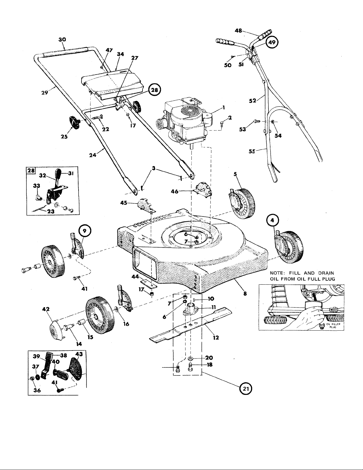
PARTS LIST FOR MOWER MODEL 111-040
Ref.
No.
1
2
Part
No.
—
710-158
DESCRIPTION
Engine
Hex Head Machine Screw
5/16-24X 1-1/2 Lg.*
714-104 Hair Pin Cotter
3
901-9691
4
502-9392
5
736-119
6
712-123 Hex Nut 5/16-24 Thread * ++
7
438-10760 Deck Assembly
8
901-9692
9
714-365 Key Hi Pro #505 * ++
10
748-189 Blade Adapter ++ 39
11
312-7713 Blade 18”
12
710-117 Hex Head Cap Screw
13
Adj. Wheel Ass’y. — L.H. Complete
Wheel Assembly
Spring Lockwasher 5/16” Screw * ++ ,
Adj. Wheel Ass’y. - R.H. Complete
Ref.
No.
29
30 718-143 Grip — Plastic
31
32
33
34
35 710-473 Truss Head Machine Screw
36 712-116 Elastic Stop Nut ** t
37 736-105
38
40 310-7492 Pivot Bar ** t
41 710-209 Sems Hex Head Cap Screw
Part
No.
310-10011
305-7470 Knob-Control tt
310-8367
901-7627
437-9998
305-7520 Knob Height Adjuster ** f
310-8313
5/16-24 X1 Lg. (Heat Treated) +-l- 3/8-16 X 5/8 Lg. *
738-102 Axle Bolt 42 305-9871 Huh Cap
14
305-7006 Fortiflex Bearing
15
736-105 Belleville Washer *
16
710-107
17
710-489 Hex Head Cap Screw
18
Hex Centerlock Nut 1/4-20 Thread *
3/8-24 X 1-1/2 Lg. (Heat Treated) ++
736-169 Spring Lockwasher 3/8” Screw * -n- 47 710-224
20
901-10769 Blade Adapter Kit -H-
21
22 710-405 Curved Head Bolt
23 732-139 Conduit and Wire ft
24 310-10009 Handle — Lower
25 305-9966 Hand Knob
746-128 Cable Clip (Not Shown)
26
710-606
27
310-10033 Throttle Control (Complete)
28
Hex'Head Cap Screw 1/4-20 x 1/2 Lg.*
¿7
3 i 0-9682 Index Plate - R.H. **
310-9683 Index Plate — L.H. t
44 310-8405
45 310-8388 Handle Bracket Assembly — R.H.
46 310-8389
48 305-7072 Grips +
310-J0029
49
50 710-148 Self Tap Screw #8-32 x 5/16” Lg. * -i-
51 394-9973
52
310-9364
53 710-106
54 712-107
55
310-8837
56
746-145
DESCRIPTION
Handle — Upper
Control Bracket Assembly ft
Feriule Assembly ft
Han dle Panel
#10-24 X 1/2 Lg.
Belleville Washer ** t
Spring Lever ** t
Reinforcement Hate
Handle Bracket Assembly — L.H.
Hex Hd. Sheet Metal Sew. #1 Ox 1/2” Lg.*
Throttle Control — Complete -i-
Cover Control +
Handle — Upper +
Hex Head Cap Screw 1/4-20 x 1-1/4” Lg.* f
Herr Center Lock Nut 1/4-20 Thread * t
Handle — Lower +
Cable Clip (Not Shown) +
* For faster service obtain standard nuts, bolts and washers
locally. If these items cannot be obtained locally, order
by part number and size as shown on the parts hst.
+ Part of Throttle Control Complete (Optional Handle 310-
10029).
ft Part of Throttle Control Complete (310-10033).
** Part of Wheel Adjustment Assembly R.H. Complete (310-
9692).
t Part of Wheel Adjustment Assembly L.H. Complete (901-
9691).
ft Part of Blade Adapter Kit Complete (‘^01-10769)
Less blade.
NOTE: This instruction manual covers various models
and all accessories shown do not necessarily apply to
your model mower.
If repairs or seivice is needed on the engine, please
contact your nearest authorized engine service outlet.
Check the “Yellow Pages”
of your telephone book under tW**
“Engines — Gasijline.” 'Yellow Pages'
FORM NO. 2868C
Page 4

ASSEMBLY INSTRUCTIONS
ASSEMBLY — Optional handle
Your new mower is shipped completely assembled with the
exception of the handle and throttle control assembly.
1. Remove lawn mower and all parts from carton. Make cer
tain that all loose parts and literature are removed from
carton before carton is discarded.,
2. Extend throttle control assembly, which is attached to
engine, to rear of mower and place on floor. CAUTION:
Do not bend or kink control wire.
3. Assemble upper handle to lower handle using four each
screws and lock nuts provided in parts bag.
4. Assemble complete handle assembly to mower so that
throttle control mounting hole in upper handle will be on
right side. Holes at bottom of lower handle are to be
fitted over studs located in front of each rear wheel
mounting position.
5. Position throttle control assembly on right hand side of
upper handle so that holes in control assembly and
handle are in line. Secure in place with screw and lock
nut found in parts bag. Secure throttle wire to lower
8. right handle tube with clips in parts bag.
6. Place the plastic control cover over the throttle control
and secure with two self-tapping screws.
OPERATION
NOTE: For shipping purposes your mower is set with the
wheels in a low cutting height position. For best results,
raise the cutting position until it is determined which height
is best for your lawn. See adjustments.
1. Service enginewith gas and oil. See Engine Manual pack
ed with lawn mower for complete instructions for the care
and maintenance of engine. READ DIRECTIONS
CAREFULLY.
2. When ready to start engine, place throttle control lever in
“START” position and start engine in accordance with
instructions in Engine Manual. After engine starts, move
throttle control lever to desired engine speed. The engine
is stopped by placing control lever in the “STOP”
position.
3. Be sure that lawn is clear of stones, sticks, wire or
other objects which could damage lawn mower or engine.
For best results and to-insure more even grass distribu
tion, do not mow when lawn is excessively wet.
4. Check blade bolts for proper tightness.
ADJUSTMENTS
CAUTION: Do not at any time make any adjustment to lawn
mower without first stopping engine and disconnecting spark
plug wire.
CUTTING HEIGHT - An adjusting plate and thumb lever at
each wheel position provides cutting height adjustment.
Each adjusting plate has five holes. Hei^t of cut will be
changed when the thumb lever is moved from one hole to
another. Simply depress thumb lever towards wheel and move
wheel and lever assembly to desired position. Cutting
height will be raised as lever is moved toward front and
lowered as lever is moved toward rear. All wheels must be
positioned in relative height of cut positions.
THROTTLE - If adjustment becomes necessary, the throttle
control wire assembly can be reset as follows:
1. Loosen, but do not remove, screw securing throttle con
trol wire assembly at engine.
2. Move throttle control lever on handle to “FAST” position.
3. Move lever, to which control wire is fastened at engine,
to full open position and re tighten screw to secure
throttle control wire assembly.
LUBRICATION
IMPORTANT: Always stop engine and disconnect spark
plug wire before cleaning, lubricating or doing any kind of
work on lawn mower.
FORM NO. 770-2383D
WHEELS: Wheel bearings are of lifetime Fortiflex. They
requite no lubrication.
THROTTLE: Periodically lubricate throttle control lever
and throttle wire assembly with a few drops of light oil
(S.A.E. No. 10 or 20) for ease of operation.
ENGINE: Follow Engine Manual for lubrication instructions.
MAINTENANCE
CUTTING BLADE - The blade may easily be removed for
grinding or replacement as follows:
1. Remove bolt and lock washer holding blade and hub
assembly to engine crankshaft.
2. Remove blade and hub assembly from engine crankshaft.
3. Remove two bolts, lock washers and nuts holding blade
to blade hub.
When sharpening blade, follow the original angle of grind as
a guide. It is extremely important that each cutting edge
receives an equal amount of grinding to prevent an unbal
anced blade. An unbalanced blade will cause excessive
vibration when rotating at high speeds and may cause
damage to the mower.
Upon reassembly, make certain all 'parts are assembled
properly and tightened securely.
DECK - The underside of mower deck should be cleaned
after each period of use as grass clippings, leaves, dirt and
other matter will accumulate. This accumulation of grass
clippings, etc. is undesirable as it will invite corrosion and
may cause an uneven discharge of grass clippings at the
next cutting.
The deck may be cleaned by tilting the mower forward or on
its left side and scraping clean with a suitable tool or by
washing with a stream of water from a garden hose.
CAUTION: Do not direct the stream of water at a hot engine
as damage to the engine may result.
STORAGE - The following steps should be taken to prepare
lawn mower for storage.
1. Clean and lubricate mower thoroughly as described in the
preceding instructions.
2. Refer to Engine Manual for correct engine storage
instructions.
3. Coat mower’s cutting blade with chassis grease to
prevent rusting.
4. Place blocks under deck to raise tires clear of floor.
5. Store mower in a dry, clean area.
USING YOUR MOWER
For best results, do not cut wet grass because it tends to
stick to underside of the mower thus preventing proper dis
charge of grass clippings. If wet grass must be cut, reduce
engine speed and walking speed to help distribute the
clippings more effectively.
New grass should be treated as wet grass, otherwise a nor
mal walking speed is about the right pace for efficient mow
ing. .. The best mowing pattern is one that allows the clip
pings to discharge towards the uncut part of the lawn. This
permits recutting of the clippings to further pulverize them.
When cutting high weeds, discharge towards cut portion,
then recut at right angles to first direction.
Lawn should be cut in the fall as long as there is growth.
PRINTED IN U.S.A.
 Loading...