

Page 1
OWNEirSGUK
ASSEMBLY • OPERATION • MAINTENANCE • PARTS
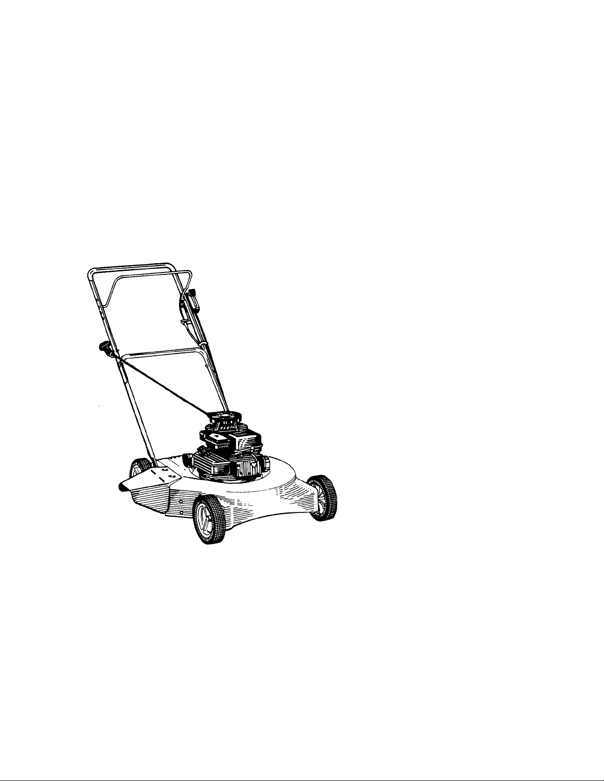
18"
$1.00
ROTARY
MOWER
Model Number
111-020R000
liû-O^L-ÛOÔ
Important: Read Safety Rules and Instructions Carefully
WARNING: This unit is equipped with an internai combustion engine and should not be used
on or near any unimproved forest-covered, brush-covered or grass-covered land unless the
engine’s exhaust system is equipped with a spark arrester meeting applicable local or state
laws (if any). If a spark arrester is used, it should be maintained in effective working order
by the operator.
In the State of California the above is required by law (Section 4442 of the California Public
Resources Code). Other states may have similar laws. Federal laws apply on federal lands.
in
AMERICA
A spark arrester for the muffler is available through your nearest engine authorized service
dealer or contact the service department, P.O. Box 360900, Cleveland, Ohio 44136.
PRINTED IN U.S.A.
FORM NO. 770-5214F
Page 2

IMPORTANT
THIS SYMBOL POINTS OUT IMPORTANT SAFETY INSTRl €TIONS WHICH, IF NOT FOLLOWED, COULD ENDANGER THE PERSONAL SAFETY
AND/OR PROPERTY OF YOURSELF AND OTHERS. RE/D AND FOLLOW ALL INSTRUCTIONS IN THIS MANUAL BEFORE ATTEMPTING
A
TO OPERATE YOUR LAWN MOWER. FAILURE TO COM ^LY WITH THESE INSTRUCTIONS MAY RESULT IN PERSONAL INJURY. WHEN
YOU SEE THIS SYMBOL- A HEED ITS WARNING.
RULES FOR SAFE OPERATION
A
DANGER; with any type of power equi »ment, carelessness or error on the part of the operator can result in serious
Your lawn mower was built to be operated according to the rules for safe operation in this manual. As
A
TRAINING
Read this owner’s guide carefully in its entirety before attempting
A"
A
to assemble or operate this machine. Be completely familiar with
the controls and the proper use of this machine before operating
it. Keep this manual in a safe piace for future and reguia reference
and for ordering replacement parts.
2. Your rotary mower is a precision piece of power equipment, not
a plaything. Therefore, exercise extreme caution at all ti mes. Your
unit has been designed to perform one job: to mow grass. Do
not use it for any other purpose.
3. Never allow children under 14 years old to operate a pow er mower.
Children 14 years old and over should only operate mo wer under
close parental supervision. Only persons well acquainted with these
rules of safe operation should be allowed to use you' mower.
4. Keep the area of operation ciear of all persons, particu arly small
children and pets. Stop engine when they are in the vicinity of
your mower to help prevent blade contact or thrown object in
jury. Although the area of operation shouid be compieh ly cieared
of foreign objects, an object may have been overlooked and could
be accidently thrown by the mower in any direction and cause
serious personal injury to the operator or any others lilowed in
the area.
PREPARATION
Thoroughiy inspect the area where the equipment is tc be used.
Remove aii stones, sticks, wire, bones and other foreiim objects
which could be picked up and thrown by the mower in any direc
tion and cause serious personal injury to the operator or any others
allowed in the area. Plan your mowing pattern to avoid discharge
of material toward roads, sidewalks, bystanders and the like.
2. Aiways wear safety glasses or eye shields during operatic n or whiie
performing an adjustment or repair, to protect eyes from foreign
objects that may be thrown from the machine in any direction.
3. Wear sturdy, rough-soied work shoes and close-fitting • lacks and
shirts. Shirts and pants that cover the arms and legs ind steel
toed shoes are recommended. Do not wear loose fittit g clothes
or jewelry. They can be caught in moving parts. Nev( r operate
a unit in bare feet, sandais, or sneakers.
4. Before working with gasoline, extinguish all cigarettes, ci{ ars, pipes
and other sources of ignition. Check the fuei level befoi e starting
the engine. Gasoiine is an extremely flammable fuel. i)o not fill
the gasoline tank indoors, while the engine is runnimj, or until
engine has been allowed to cool for at least two min jtes after
running. Replace gasoline cap securely and wipe off aiy spilled
gasoline before starting the engine as it may cause a fire or
explosion.
5. Disengage the self-propelled mechanism or drive clutcl i on units
so equipped before starting the engine.
6. The blade control handle is a safety device. Never attempt to bypass
its operation. Doing so makes the safety device inopeiative and
may result in personal injury through contact with th i rotating
blade. The blade control handle must operate easily in b oth direc
tions and automatically return to the disengaged posti ion when
released.
7. Never attempt to make a wheel or cutting height adjustn lent while
the engine is running.
8. Never operate the mower in wet grass. Always be sui e of your
footing. A slip and fall can cause serious personal injury. Keep
a firm hold on the handle and walk, never run. Mow only i i daylight
or in good artificial light.
injury. If you violate any of these rules, you may cause serious injury to yourself or others.
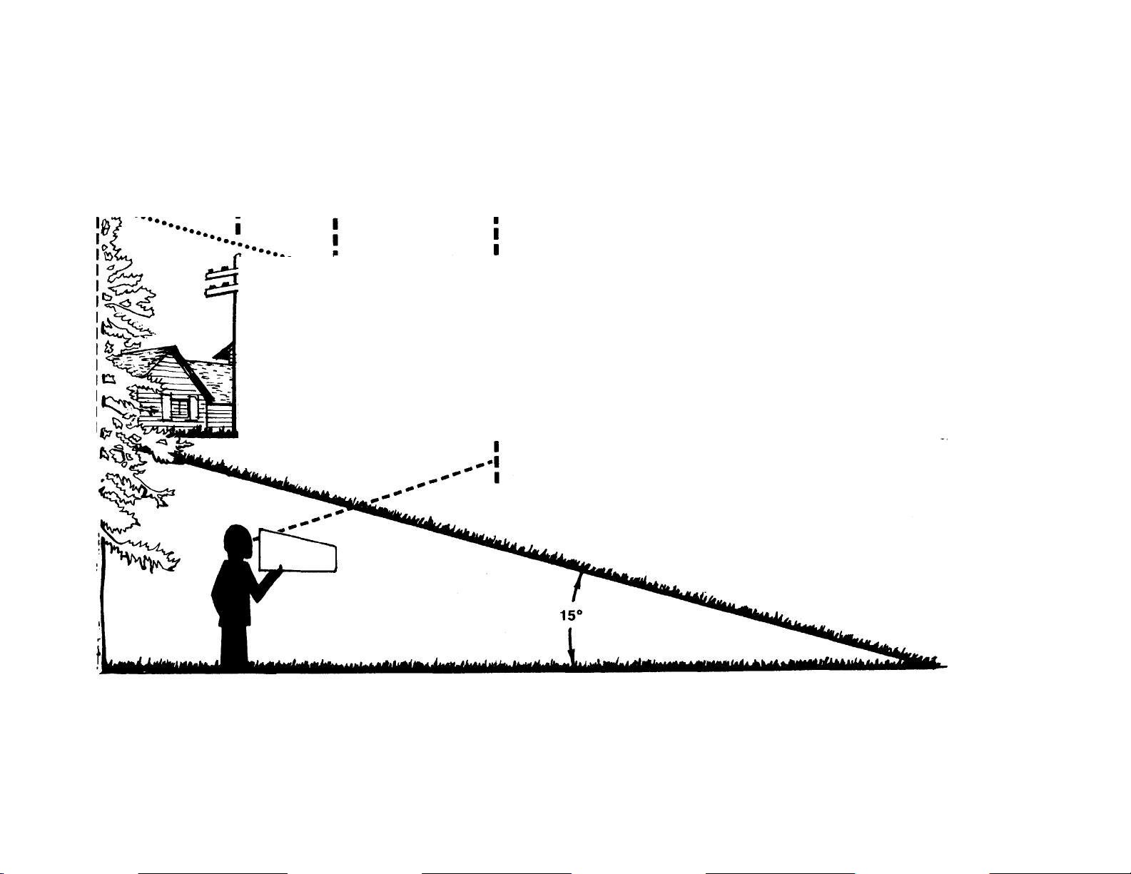
9. For your safety, use the slope gauge included as part of this manual
to measure slopes before operating this unit on a sloped or hilly
area. If the slope is greater than 15° as shown on the slope gauge,
do not operate this unit on that area or serious injury could result.
OPERATION
Do not change the engine governor settings or overspeed the
A
A
engine. Excessive engine speeds are dangerous.
2.
Do not put hands or feet near or under rotating parts. Keep clear
of the discharge opening at all times as the rotating blade can
cause injury.
Stop the blade when crossing gravel drives, walks or roads.
After striking a foreign object, stop the engine, remove the wire
from the spark plug, and thoroughly inspect the mower for any
damage. Repair the damage before restarting and operating the
mower.
5.
If the equipment should start to vibrate abnormally, stop the engine
and check immediately for the cause. Vibration is generally a warn
ing of trouble.
Shut the engine off and wait until the blade comes to a complete
stop before removing the grass catcher or unclogging the chute,_
The cutting blade continues to rotate for a few seconds after t'
engine is shut off. Never place any part of the body in the bla*.
area until you are sure the blade has stopped rotating.
7.
Before cleaning, repairing or inspecting, make certain the blade
and all moving parts have stopped. Disconnect the spark plug wire,
and keep the wire away from the spark plug to prevent accidental
starting.
Do not run the engine indoors.
Never cut grass by pulling mower toward you. Mow across the
face of slopes, never up-and-down. Exercise extreme caution when
changing direction on slopes. Do not mow excessively steep slopes.
Always be sure of your footing. A slip and fall can cause serious
personal injury.
10.
Never operate mower without proper guards, plates or other safety
protective devices in place.
11.
Muffler and engine become hot and can cause a burn. Do not
touch.
MAINTENANCE AND STORAGE
1. Check the blade and engine mounting bolts at frequent intervals
for proper tightness. Also visually inspect blade for damage (e.g.
bent, cracked). Replace with blade which meets original equip
ment specifications.
2. Keep all nuts, bolts, and screws tight to be sure the equipment
is in safe working condition.
3. Never store the mower with gasoline in the tank or gas containers
inside of a building where fumes may reach an open flame or spark
(e.g. gas hot water heater). Allow the engine to cool before stor
ing in any enclosure.
4. To reduce fire hazard, keep the engine free of grass, leaves and,
excessive oil.
5. Check the grass catcher bag frequently for wear or deterioratio
Replace a worn or damaged bag immediately. For safety protec
tion, replace only with new bag meeting original equipment
specifications.
Page 3
-OUT MIC
V /
nis Line-
USE THIS SHEET AS A GUIDE TO DETERMINE SLOPES WHERE YOU MAY NOT OPERATE SAFELY.
SIGHT AND HOLD THIS LEVEL WITH A VERTICAL TREE
----------------^
----------------------------------
^ .......................................
^ I ...................................................................................
.....
I
A POWER POLE
........
_ ■
A CORNER OF A BUILDING
OR A FENCE POST
:k
(D
(D
T3
0)
(0
(D
(D
» "O
CO
s m
■o
(D
0)
O
(D
C
c
<D
o
n
CO
AC
WARNING
Do not mow on inclines with a slope in excess of 15 degrees (a rise of approximately 2V2 feet every 10 feet). A
riding mower could overturn and cause serious injury. If operating a walk-behind mower on such a slope, it is
extremely difficult to maintain your footing and you could slip, resulting in serious injury.
Operate RIDING mowers up and down slopes, never across the face of slopes.
Operate WALK-BEHIND mowers across the face of slopes, never up and down slopes.
<D
(D
“t
(D
3
o
(D
Page 4
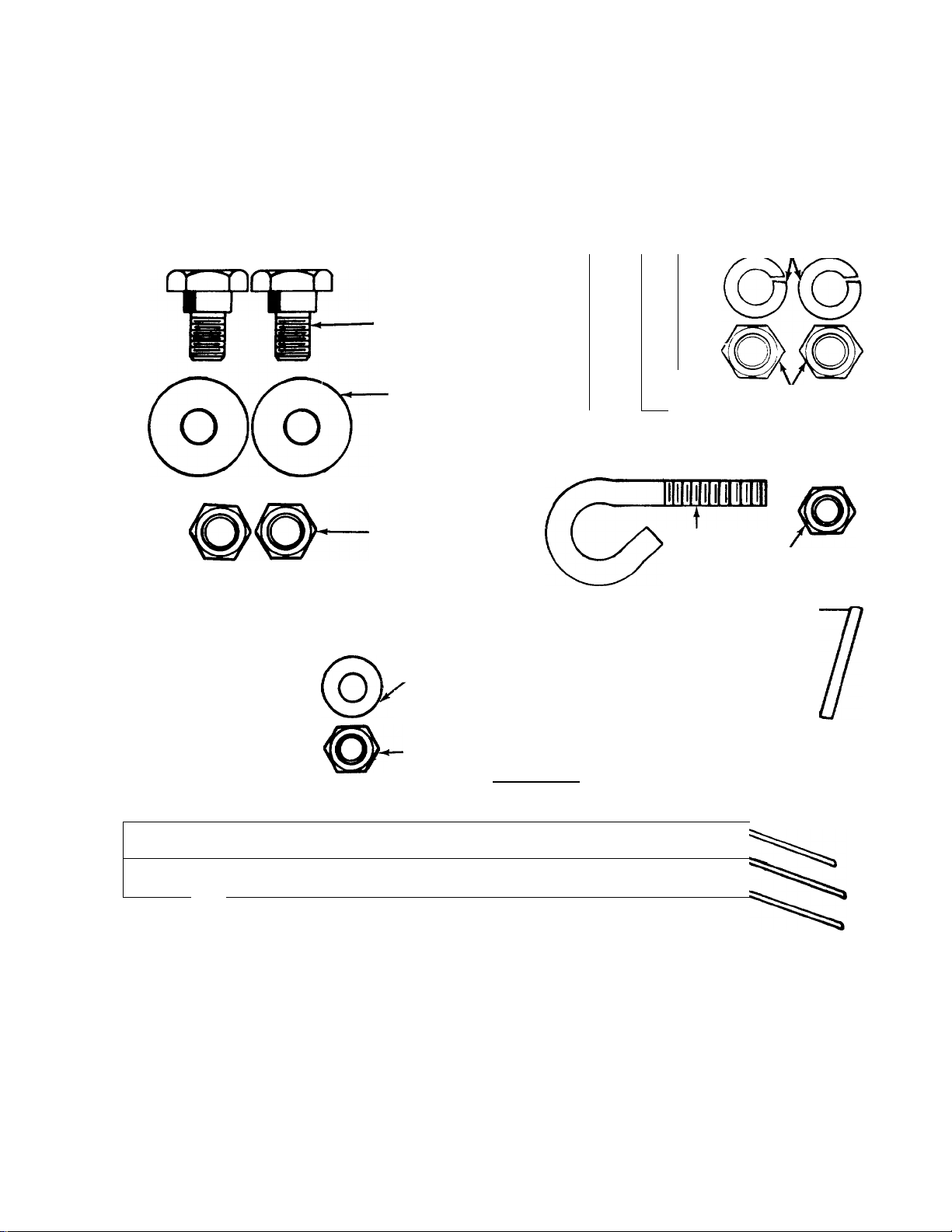
CONTENTS OF HARDWARE PACK
Remove this sheet from your owner’s manual and lay the hardware on the illustration for identification purposes. After assembly,
keep the Slope Gauge which is on the reverse sid5 of this sheet for future use.
(Hardware pack may contain extra items which iire not used on your unit. Part numbers are shown in parentheses.)
ATTACHING THE
LOWER HANDLE
ATTACHING THE CABLE BRACKET AND
OPTIONAL THROTTLE CONTROL
______________
(736-0175)
Ì
7
Hex Bolt
V4-20 X 1-7/8" Long
(710-1216)
SECURING THE CABLES
Shot Ider
Bo ts
(738-11140)
Cu pped
Wa shers
5/1 <i" I.D.
(736-0242)
Hex Lock
Nuts
(712-0129)
Sprirg Washer
V " I.D.
Cable
Bracket
(17174)
h ex Nut
Vi-5:0 Thread
(712-0287)
B
[pililililililM
ATTACHING THE
UPPER HANDLE
I 1
ATTACHING THE
STARTER ROPE
n
(710-0671)
(710-1205)
Curved
Head
Bolts
Rope
Guide
Split Washers
5/16" I.D.
(736-0119)
Hex Nuts
5/16-18 Thread
(712-0267)
Hex Lock Nut
Vi-20 Thread
(712-0324)
o
uniis
Units With No Remote Throttle Control:
Hex Bolt
■~Vi-20 X 1" Long
(710-0597)
O
c
n
Axle Bolts(738-0533)
I t
0
INCHES
LI
n
INSTALLATION OF WHEELS
(This hardware is shown one-half size)
I
_LI
li
Dcrzpcrzxi
I I I I I I I I i I I I I I I I I I I I
Cable Ties
(726-0240)''
Cupped Washers
3/8" I.D. X 7/8" O.D.
(736-0105)-
Cupped Washers
3/8" I.D. X
1-1/8" O.D.
(736-0331)
------------
Hex Nuts
3/8-16 Thread-
(712-0798)
,^(oXoXo)
■ 0000
Page 5

ASSEMBLY INSTRUCTIONS
IMPORTANT: This unit is shipped WiTHOUT GASOLINE
or OIL. After assembly, service engine with gasoiine and
oii as instructed in the separate engine manual packed
with your unit.
NOTE: Reference to right or left hand side of the mower is
observed from the operating position.
Tools Required for Assembiy
(1) 1/2" Wrench
(2) 7/16" Wrenches
(2) 9/16" Wrenches
(1) Adjustable Wrench
(Two 6" Adjustable Wrenches may be used instead of the
above.)
UNPACKING
1. Remove the lawn mower from the carton by opening the
top flaps and lifting the unit out. Be careful of the staples.
Make certain all parts and literature have been removed
from the carton before the carton is discarded.
2. Disconnect and ground the spark plug wire against the
engine.
3. Stretch out all control cables and place on the floor. Be
careful not to bend or kink the cables at any time during
assembly.
4. Remove page four from this manual and lay the contents
of the hardware pack on the illustration for identification.
ATTACHING THE LOWER HANDLE (Hardware A)
Attach the lower handle by lining up the upper slotted hole
in lower handle with the mounting hole on deck. Place
-shoulder bolt through lower handle and deck. See figure 1.
Place cupped washer on the shoulder bolt, with the cupped
side of the washer against the baffle. Secure with hex lock
nut.
FIGURE 1.
FIGURE 2.
Washer
Hole in
Biade Controi
Handie
ATTACHING THE UPPER HANDLE (Hardware B)
1. Place the upper handle in position over the lower han
dle. The hole in the side of the blade control handle (at
tached to the upper handle) must be on the left side.
2. Secure the upper handle to lower handle using the
curved head bolts, split washers and hex nuts as shown
in figure 2.
AHACHING THE CABLE BRACKET AND DPTIDNAL THRDTTLE CDNTRDL (Hardware D)
If your mower is equipped with an optional remote throttle
control, it is already attached to the engine. Attach the throt
tle control to the left side of upper handle as follows. See
-figure 2.
NOTE: If your mower does not have a remote throttle con
trol, attach the cable bracket using the 1" long hex bolt pro
vided and following steps 2 and 4 only.
1. Route the throttle control cable inside the legs and
beneath the upper bar of the lower handle.
2. Place cable bracket against left side of upper handle,
lining up the hole in the bracket with the bottom hole in
upper handle. Place 1/4" hex bolt through cable bracket
and handle, from the inside to the outside.
3. Place throttle control on the hex bolt (outside of upper
handle), with the throttle lever facing upward.
4. Secure with spring washer (cupped side against the throt
tle control) and hex nut.
Page 6

“Z” Fitting
ATTACHING THE BRAKE CABLE
1. The brake cable is attached to the engine, and has a “Z”
fitting on the loose end. Route the brake cable below the
lower handle. Place end of cable through the hole in the
-bracket as shown in figure 3. Be careful not to bend or
kink the cable at any time. Push the plastic fitting until
it locks into the hole in the bracket.
WARNING: Brake cable must be assembled as
A
2. Hook the “Z” end of the brake cable into the hole in the
shown for proper blade brake operation.
blade control handle from the inside to the outside as
shown in figure 3.
FIGURE 3.
V
SECURING THE CABLE(S) (Hardware E)
Secure the cable(s) to the left side of the handle as follows.
WARNING: When attaching the control cables,
the cables must be routed to avoid contact with
A
1. Insert posts on cable ties into holes provided on the in
-------
2. Secure the cable(s) with the cable ties. See figure 4B.
3. Trim excess ends of cable ties.
ali sharp edges and hot surfaces to prevent
damage to the cables, which wili render the con
trols inoperative.
side of the handle, one on the upper handle and two on
the lower handle. The holes may be either on the inside
or outside of the handles. See figure 4A.
ATTACHING THE STARTER ROPE (Hardware C)
1. The starter rope is inside the top of the engine. Additional
rope may be wound around the starter handle. If so, un-
------
wind the rope from the handle.
2. With the spark plug wire disconnected and grounded,
depress the blade control handle and pull the rope out
of the engine.
3. Place the rope guide around the starter handle, so the
rope guide is positioned as shown (bends downward
slightly). Insert the rope guide into the handle, and secure
with hex lock nut.
FIGURE 5.
Four
INSTALLATION OF WHEELS (Hardware F)
The four holes provide four cutting heights for your mower.
Use the same hole location for all four wheels when assem
bling. If wheels are to be assembled in the lowest cutting posi
tion (highest hole in the deck), refer to the note below.
-To assemble the wheels: (See figure 6)
1. Place axle bolt through wheel.
2. Place one smaller cupped washer on axle bolt, with the
cupped side of washer toward the deck (away from
wheel).
3. Secure wheel to deck with one larger cupped washer on
the inside of the deck (cupped side against the deck) and
hex nut. Tighten securely.
4. Assemble the other wheels in the same manner.
NOTE: If the lowest cutting position (highest hole in the deck)
is used, it is necessary to place the larger washer on the out
side of the deck and the smaller washer on the inside.
Page 7

FINAL ASSEMBLY OF MOWER
1. The chute deflector on your mower is held in an upright
position by a block for shipping purposes only. This ship
ping block must be removed and discarded before the
------
mower is put into operation. See figure 7.
To remove the shipping block, move the spring-loaded
chute toward the engine by pushing above the shipping
block. Remove the block and carefully lower the chute
into operating position, keeping fingers out of the way.
2. Make certain all nuts and bolts are tightened securely.
CONTROLS
FIGURE 8.
BLADE CONTROL HANDLE
WARNING: This control mechanism is a safety
A
The blade control handle is located on the upper handle of
the mower. See figure 8. The blade control handle must be
depressed in order to operate the unit. Release the blade con
trol handle to stop the engine and blade.
A
THROTTLE CONTROL (Optional)
The throttle control is located on the left side of the upper
handle or on the engine. It is used to regulate the engine
speed. The engine should be started with the engine in the
FAST or START position.
A
RECOIL STARTER
The recoil starter handle is attached to the handle. See figure
8. Stand behind the unit in the operating position to start the
unit.
device. Never attempt to bypass its operations.
WARNING: The blade will be rotating whenever
the engine is running.
WARNING: The throttle control cannot be used
to stop the engine.
OPERATION
TO REDUCE THE RISK OF INJURY, DO NOT
OPERATE MOWER UNLESS REAR TRAILING
SHIELD AND THIS GUARD OR ENTIRE
GRASS CATCHER IS IN ITS PROPER PLACE.
FIGURE 9.
Keep hands and feet away from the chute area on cutting
deck. See figure 9.
The operation of any lawn mower can result in foreign
objects being thrown into the eyes, which can result in
severe eye damage. Always wear safe
ty glasses or eye shields. We recom
mend wide vision safety mask for over
spectacles or standard safety glasses.
GAS AND OIL FILL-UP
Service the engine with gasoline and oil as instructed in
the separate engine manual packed with your mower. Read
instructions carefully.
WARNING: Never fill fuel tank indoors, with
engine running or until the engine has been
A
TO START ENGINE AND ENGAGE BLADE
1. Attach spark plug wire securely to spark plug.
2. Move the throttle control lever (if so equipped) to FAST
3. Tecumseh engines only: Prime engine as instructed in
allowed to cool for at least two minutes after
running.
or START position.
the separate engine manual.
Page 8

4. Standing behind the unit, depress the blade conti ol han
dle and hold it against the upper handie as shown in
figure 10.
5. Grasp the recoil starter handle as shown and pi II back
rapidly, extending rope fully. Return it slowly to tl le rope
guide bolt.
6. After engine starts, move throttle control lever to > fesired
engine speed.
FIGURE 10.
NOTE: If any problems are encountered, refer to the Trouble
Shooting Guide on page 12.
WARNING: If you strike a foreign object, stop the
engine. Remove wire from spark plug,
A
thoroughly inspect the mower for any damage,
and repair the damage before restarting and
operating the mower. Extensive vibration of the
mower during operation is an indication of
damage. The unit should be promptly inspected
and repaired.
ADJUSTMENTS
WARNING: Do not at any time make any adjust
ment to lawn mower without first stopping
A
CUTTING HEIGHT ADJUSTMENT
Adjustment may be made by removing and moving axle bolts
to desired position. Cutting heights will be raised as axle bolts
are moved to a lower hole and lowered as axle bolts are
moved to a higher hole in the deck. All axle bolts must be
mounted in the same relative position. Cupped washers must
be assembled so that the cupped side of the washers are
against the deck. Refer to figure 6.
engine and disconnecting spark plug wire.
TO STOP ENGINE AND BLADE
1. Release the blade control handle to stop the enc ine and
blade.
WARNING: The blade continues to rota:e for a
A
2. Disconnect the spark plug wire and ground it ag: linst the
few seconds after the engine is shut o< f.
engine to prevent accidental starting while eq jipment
is unattended.
USING YOUR ROTARY MOWER
Be sure that lawn is clear of stones, sticks, wire, or other ob
jects which could damage lawn mower or engine. Such ob
jects could be accidently thrown by the mower in any ( lirection
and cause serious personal injury to the operator anc others.
For best results, do not cut wet grass because it tends to stick
to the underside of the mower, preventing proper di: »charge
of grass clippings, and could cause you to slip and f ill. New
grass or thick grass may require a narrower cut.
The best mowing pattern is one that allows the clip 3ings to
discharge towards the uncut part of the lawn. This permits
recutting of the clippings to further pulverize them. W nen cut
ting high weeds, discharge towards cut portion, then recut
at right angles to first direction.
For best results, cut off one-third or less of the tot£ I length
of the grass. Lawn should be cut in the fall as long is there
is growth.
This mower is designed to be operated at full throttle to give
you the best cut and do the most effective job of bag ging the
cut grass.
THROTTLE CONTROL ADJUSTMENT
(Optional Equipment)
If the throttle control requires adjustment or has been re
placed, adjust the throttle control as follows.
1. Loosen (do not remove) the screw on the cable clamp
so that the cable will move freely under the clamp. See
figure 11.
2. Place the throttle control lever on the handle all the way
forward to START position.
3. Place the control lever on the engine in the full open posi
tion by pushing it as far toward the outside (Briggs and
Stratton engine) or rear (Tecumseh engine) of the engine
as it will go. Tighten the screw on the cable clamp to
secure the cable in this position.
Cable
.Clamp
Control
Lever
On Engine
FIGURE 11 A.—Briggs and Stratton Engine
Page 9

FIGURE 11B.—Tecumseh Engine
CARBURETOR ADJUSTMENTS
WARNING: If any adjustments are made to the
:
A
Minor carburetor adjustment may be required to compen
sate for differences in fuel, temperature, altitude and load.
Refer to the separate engine manual packed with your mower
for carburetor adjustment information.
NOTE: A dirty air cleaner will cause an engine to run rough.
Be certain air cleaner is clean and attached to the carburetor
before adjusting carburetor. Refer to the separate engine
manual.
engine while the engine is running (e.g. car-
I buretor), keep clear of all moving parts. Be
'
careful of heated surfaces and muffler.
LUBRICATION
WARNING: Always stop engine and disconnect
spark plug wire before cleaning, lubricating or
A
Blade Control—Lubricate the pivot points on the blade con
trol handle and the brake cable at least once a season with
light oil. See figure 12. The blade control must operate free
ly in both directions.
FIGURE 12.
Chute Deflector—The torsion spring and pivot point should
be lubricated periodically with light oil to prevent any rust or
binding. Deflector must work freely.
Wheels—The wheels require no lubrication. However, if the
wheels are removed for any reason, lubricate the surface of
the axle bolt and the inner surface of the wheel with light oil.
A 4 oz. plastic bottle of light oil lubricant is available. Order
part number 737-0170. Engine oil may also be used.
doing any kind of work on lawn mower.
Pivot
Point
Engine—Follow engine manual for lubrication instructions.
Throttle (Optional)—Periodically lubricate throttle control
lever and throttle wire assembly with a few drops of light oil
for ease of operation.
MAINTENANCE
WARNING: Be sure to disconnect and ground
the spark plug wire before performing any
A
NOTE: When tipping the unit, empty the fuel tank and keep
engine spark plug side up.
TROUBLE SHOOTING
Refer to page 12 of this manual for trouble shooting infor
mation.
CUTTING BLADE
When removing the cutting blade for sharpening or replace
ment, protect hands by using heavy gloves or a rag to grasp
the cutting blade. Remove the bolt and bell washer which
hold the blade and adapter to the engine crankshaft. Remove
the blade and adapter from the crankshaft.
If the blade or blade adapter needs replacing, remove the
two small bolts, lock washers and nuts which hold the blade
to the adapter.
A
When sharpening the blade, follow the original angle of grind
as a guide. It is extremely important that each cutting edge
receives an equal amount of grinding to prevent an unbal
anced blade. An unbalanced blade will cause excessive vibra
tion when rotating at high speeds, may cause damage to the
mower and could break, causing personal injury.
It is recommended that the blade always be removed from
the adapter for the best test of balance.
The blade can be tested by balancing it on a round shaft
screwdriver. Remove metal from the heavy side until It
balances evenly.
Before reassembling the blade and the blade adapter to the
unit, lubricate the engine crankshaft and the inner surface
of the blade adapter with light oil. Lubricating the bolt holes,
bolts and inner surface of the nuts with light oil is also recom
mended. A 4 oz. plastic bottle of light oil lubricant is available.
Order part number 737-0170. Engine oil may also be used.
When replacing the blade, be sure to install the blade with
the side of the blade marked “Bottom” (or with part number)
facing the ground when the mower is in the operating position.
Blade Mounting Torque
Center Bolt and Blade Adapter Bolts:
375 in. lb. min., 450 in. lb. max.
To insure safe operation of your unit, all nuts and bolts must
be checked periodically for correct tightness.
DECK
The underside of the mower deck should be cleaned after
each use to prevent a buildup of grass clippings, leaves, dirt
repairs or maintenance.
WARNING: Periodically inspect the blade
adapter for cracks, especially if you strike a
foreign object. Replace when necessary.
Page 10

or other matter. If this debris is allowed to accumulate!, it will
invite rust and corrosion, and may cause an uneven dis charge
of grass clippings at the next cutting.
The deck may be cleaned by tilting the mower and sc raping
clean with a suitable tool (make certain the spark plug wire
is disconnected).
ENGINE
Refer to the separate engine manual for engine main
tenance instructions.
Maintain engine oil as instructed in the separate sngine
manual packed with your unit. Read and follow instructions
carefully.
Service air cieaner every 25 hours under normal conditions.
Clean every few hours under extremely dusty condition s. Poor
engine performance and flooding usually indicates tiat the
air cleaner should be serviced. To service the air c eaner,
refer to the separate engine manual packed with yo jr unit.
The spark plug should be cleaned and the gap resut once
a season. Spark plug replacement is recommendec at the
start of each mowing season; check engine manual dr cor
rect plug type and gap specifications.
Model 020R
Clean the engine regularly with a cloth or brush. Keep the
cooling system (blower housing area) clean to permit proper
air circulation which is essential to engine performance and
life. Be certain to remove all grass, dirt and combustible debris
from muffler area.
OFF-SEASON STORAGE"
The following steps should be taken to prepare lawn mower
for storage.
1. Clean and lubricate mower thoroughly as described in
the lubrication instructions.
2. Refer to engine manual for correct engine storage in
structions.
3. Coat mower’s cutting blade with chassis grease to pre
vent rusting.
4. Store mower in a dry, clean area.
NOTE: When storing any type of power equipment in an un~
ventiiated or metai storage shed, care should be taken to rust
proof the equipment. Using a light oil or silicone, coat the
equipment, especially cables and all moving parts.
10
Page 11

Model 020R
PARTS LIST FOR MODEL 020R ROTARY MOWER
£F.
NO.
10 726-0106 Push Nut V4" Rod
11
12
13
14
15
16 710-0654A Hex Wash. Hd. TT-Tap Scr. 41
17
18 710-0671
19 710-1205 Rope Guide
20 712-0267
21 736-0119 L-Wash. 5/16" I.D.*
22
J-^3 736-0242 Bell-Wash. .345" I.D. x .88"
26
27
PART
NO.
1
747-0748 Control Handle—L.H. 28
2
3
* *
742-0518
CODE DESCRIPTION
Plastic Wheel Ass’y- 6 x 1.50
18" Blade 31
REF.
NO.
29
PART
NO.
753-0484
736-0452
14835
CODE
4 710-0227 Hex Wash. Hd. AB-Tap Scr. 32 710-0776A
#8 X .50" Lg. (B&S)t
5 749-0372B Lower Handle
6
7 11681
—
638
Engine 34 712-0798
Chute Deflector Ass’y- Comp.
731-1077 N
33
35 736-0105 Bell-Wash. .400" I.D. x .88"
8 11130 Adapter Plate O.D.
9 711-0555
Pivot Pin
36
738-0213
732-0253 Torsion Spring 37 712-0241
710-0289
712-0287
736-0329 L-Wash. 1/4" I.D.*
14922A
638 18" Deck Ass’y.
Hex Bolt 1/4-20 X .50" Lg.* 38 736-0169
Hex Nut 1/4-20 Thd.*
39 746-0553 Control Cable—36" (B&S)
746-0557
40 710-1216 N
710-1055 Hex Bolt 3/8-24 x 1" Lg.
3/8-16 X 1.00" Lg.
42 746-0800
726-0240 Cable Tie
Curved Carriage Bolt 5/16-18 746-0830
X 1.38" Lg.
43 17174
Hex Nut 5/16-18 Thd.* 44
736-0175
45 712-0287
712-0429 Hex Ins. L-Nut 5/16-18 Thd.
749-0756A
46
47 710-0429
4
738-0140 Shoulder Bolt .437" Dia. x .180
710-1044 Hex Bolt 3/8-24 x 1.5" Lg.
(Grade 5)
712-0324 Hex L-Nut 1/4-20 Thd.
48 751-0369
49 12894A
50 736-0331
DESCRIPTION
Blade Adapter Kit
Bell-Wash. .39" I.D.
Retaining Strip
Hex Wash. Hd. AB-Tap Scr.
1/4" X .62" Lg.
Rear Flap Ass’y.
Hex Nut 3/8-16 Thd.*
Shid. Bolt .498" Dia. x 1.450"
Lg-
Hex L-Nut 3/8-24 Thd.
L-Wash. 3/8" I.D.*
Control Cable—47" (Tec.)
Hex Bolt 1/4-20 X 1.875" Lg.
Throttle Control Ass’y. Comp.
(B&S)t
Throttle Control Ass’y. Comp.
(Tec.)t
Cable Mounting Brkt.
Spr. Wash. .27" I.D. x .57" O.D.
Hex Nut 1/4-20 Thd.*
Upper Handle
Hex B-Tap Scr. #10 x .38" Lg.
(B&S)t
Casing Clamp (B&S)t
Casing Clamp (B&S)t
FI-Wash. .398" I.D. X 1.13"
tOptional Parts
*For faster service obtain standard nuts, bolts and washers locally.
If these Items cannot be obtained locally, order by part number and
size as shown on parts list.
NOTE
This instruction manual covers various models, and
all specifications shown do not necessarily apply to
your model. Specifications subject to change
without notice or obligation.
NOTE: The engine is not und
the mower manufacturer. . .
service is needed on the
contact your nearest author
ized engine service outlet.
Check the “Yellow Pages” of
your telephone book under
“Engines—Gasoline.”
er warranty by
If repairs or
ngine, please
Find It Fast
In The
Yellow Pages
—-—
CODE: N notates a new part (not previously existing). A three digit
number is the color code. Specify color code as shown below if
color or finish is important when ordering parts, [i.e., 638 for Red
Finish].
Color Codes
456—Radiant Tangerine
460—Green Flake
483—Charcoal Gray
498—Yellow
499—Beige
621—Brilliant Fire Mist
629—Silver Flake
630—Metallic Blue
637—Black
638—Red
640—Green
646—CM Blue
'Wheel Assembly
734-0839
734-1175
11
Page 12

TROUBLE SHOOTING GUIDE
Trouble Possibli! Cause(s)
Engine fails to start 1. Blade control handle disengaged.
Engine runs erratic
Engine overheats 1. Engine oil level low.
Occasional skip
(hesitates) at high speed
2. Spark plug wire disconnected.
3. Throttle control ever not in FAST
or START positian.
4. Fuel tank empty, or stale fuel.
5. Blocked fuel lino.
6. Faulty spark plug.
7. Engine flooded.
1. Unit running in START position.
2. Spark plug wire loose.
3. Blocked fuel lino or stale fuel.
4. Vent in gas cap plugged.
5. Water or dirt in fuel system.
6. Dirty air cleaner,
7. Carburetor out of adjustment.
2. Air flow restricted.
3. Carburetor not adjusted properly.
1. Carburetor idle speed too slow.
2. Spark plug gap too close.
3. Carburetor idle nlxture adjustment
improperly set.
Corrective Action
1. Engage blade control handle.
2. Connect wire to spark plug.
3. Move throttle lever to FAST or
START position.
4. Fill tank with clean, fresh gasoline.
5. Clean fuel line.
6. Clean, adjust gap or replace.
7. Remove spark plug, dry the plug, and
crank engine with plug removed and
throttle in off position. Replace spark
plug, connect wire and resume starting
procedures.
1. Move throttle lever to FAST position.
2. Connect and tighten spark plug wire.
3. Clean fuel line; fill tank with clean,
fresh gasoline.
4. Clear vent.
5. Drain fuel tank. Refill with fresh fuel.
6. Clean air cleaner.t
7. Adjust carburetor.-)-
1. Fill crankcase with proper oil.
2. Remove blower housing and clean.f
3. Adjust carburetor.f
1. Adjust carburetor.f
2. Adjust gap to .030".
3. Adjust carburetor.f
Idles poorly
Excessive vibration
Mower will not
discharge grass
Uneven cut
tRefer to separate engine manual packed with your unit.
Note: For repairs beyond the minor adjustments listed above, please contact your local authorized service dealer.
NOTE: The use of any accessory on this Rotary Mower other than those manufactured by the mower
manufacturer is not recommended. GRA!5S CATCHER model 086 is available as optional equipment for
the mowers shown in this manual.
WARNING: To reduce the risk of injury, do not operate mower unless rear trailing shield
and guard or entire grass cat :her is in its proper place.
1. Spark plug foulod, faulty or gap
too wide.
2. Carburetor impraperly adjusted.
3. Dirty air cleaner.
1. Cutting blade loose or unbalanced.
2. Bent cutting blade.
1. Engine speed too low.
2. Wet grass.
3. Excessively high grass.
1. Wheels not pos tioned correctly.
2. Dull blade.
1. Reset gap to .030" or replace
spark plug.
2. Adjust carburetor.f
3. Clean air cleaner.-j-
1. Tighten blade and adapter.
Balance blade.
2. Replace blade.
1. Set throttle between 3/4 and full throttle.
2. Do not mow when grass is wet; wait
until later to cut.
3. Mow once at a high cutting height, then
mow again at desired height or make a
narrower cutting swath (1/2 width).
1. Place all four wheels in same height
position.
2. Sharpen or replace blade.
A
NOTE: Under normal usage bag material is subject to wear and should be checked periodically. Be sure
any replacement bag complies with the mower manufacturer’s recommendations. For replacement bags,
use only factory authorized replacement bag part number 764-0271.
REPLACEMENT PARTS • P.O. BOX 360900 • CLEVELAND, OHIO 44136
 Loading...