

Page 1
OWNER'S GUIDE
ASSEMBLY • OPERATION • MAINTENANCE • PARTS
$1.00
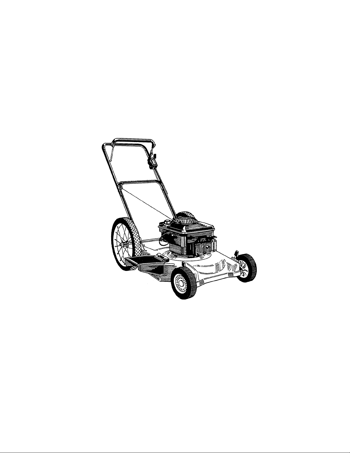
22"
ROTARY
Model Number
110A508R000
MOWER
Important: Read Safety Rules and Instructions Carefully
PRINTED IN U.S.A.
FORM NO. 770-7195E
Page 2

INDEX
felbpe Gauge
Contents of Hardware Pack
Rules for Safe Operation
Assembly
Controls......................................................................9
Operation
Adjustments
Lubrication...............................................................11
Maintenance
Off-Season Storage
Trouble Shooting Guide
Repair Parts ............................................................14
Parts Information
NOTE: The engine is not under warranty by
the mower manufacturer. ..If repairs or
service is needed on the engine, please
contact your nearest author
ized engine service outlet.
Check the “Yellow Pages” of
your telephone book under
“Engines—Gasoline.”
.............................................................
........................................
...........................................
...................................................................
...................................................................
.............................................................
.....................................................
..........................................
.........................................
.......................................
Find It Fast
In The
Yellow Pages
... 12
. . .12
Bach Cover
10
13
Dear Customer,
So often throughout the year we are all in a
3
4
5
6
9
rush to meet our daily obligations.
However, we at MTD Products Inc are tak
ing a quick moment out to say.. .
“Thank you for your business.”
Sincerely,
MTD PRODUCTS INC
INSTRUCTIONS GIVEN WITH THIS SYM
BOL ARE FOR PERSONAL SAFETY. BE
A
SURE TO FOLLOW THEM.
NOTE
This instruction manual covers various
models and all specifications shown
do not necessarily apply to your
model. Specifications subject to
change without notice or obligation.
NOTE: The use of any accessory on th s Rotary Mower other than those manufactured by the mower
manufacturer is not recommended. GRASS CATCHER Model is available as optional equipment for the
mower shown in this manual. "7 ^
WARNING: To reduce the risk o1 injury, do not operate mower unless rear trailing shield and
A
NOTE: Under normal usage bag material ii i subject to wear and should be checked periodically. Be sure any
replacement bag complies with the mower manufacturer’s recommendations.
WARNING: This unit is equipped with an internai combustion engine and should not be used on or near any unim
proved forest-covered, brush-covered or grass-covered land unless the engine’s exhaust system is equipped with ’
a spark arrester meeting applicable local or state laws (if any). If a spark arrester is used, it should be maintained
in effective working order by the operator.
In the State of California the above is requirtid by law (Section 4442 of the California Public Resources Code)..
Other states may have simiiar laws. Federal la' vs apply on federal lands. A spark arrester for the muffler is available
through your nearest engine authorized service dealer.
guard or entire grass catcher is i n its proper place.
Page 3

USE THIS SHEET AS A GUIDE TO DETERMINE SLOPES WHERE YOU MAY NOT OPERATE SAFELY
i
k
SIGHT AND HOLD THIS LEVEL WITH A VERTICAL TREE
f
---------------^
--------------------------------
!
................. oj
A POWER POLE
.........
A CORNER OF A BUILDING
?s
OR A FENCE POST
(D
O
■a
■
0)
C/i
,
.
.......
0)
or
(D
(D
H
0)
0)
0)
“4*
n>
■a
0)
o
(D
C
c
"I
o
—%
(0
—41
(i>
“1
(D
3
o
Q
o
o
AC WARNING ^
Do not mow on inclines with a slope in excess of 15 degrees (a rise of approximately 2V2 feet every 10 feet). A
riding mower could overturn and cause serious injury. If operating a walk-behind mower on such a slope, it is
extremely difficult to maintain your footing and you could slip, resulting in serious injury.
Operate RIDING mowers up and down slopes, never across the face of slopes.
Operate WALK-BEHIND mowers across the face of slopes, never up and down slopes.
Page 4
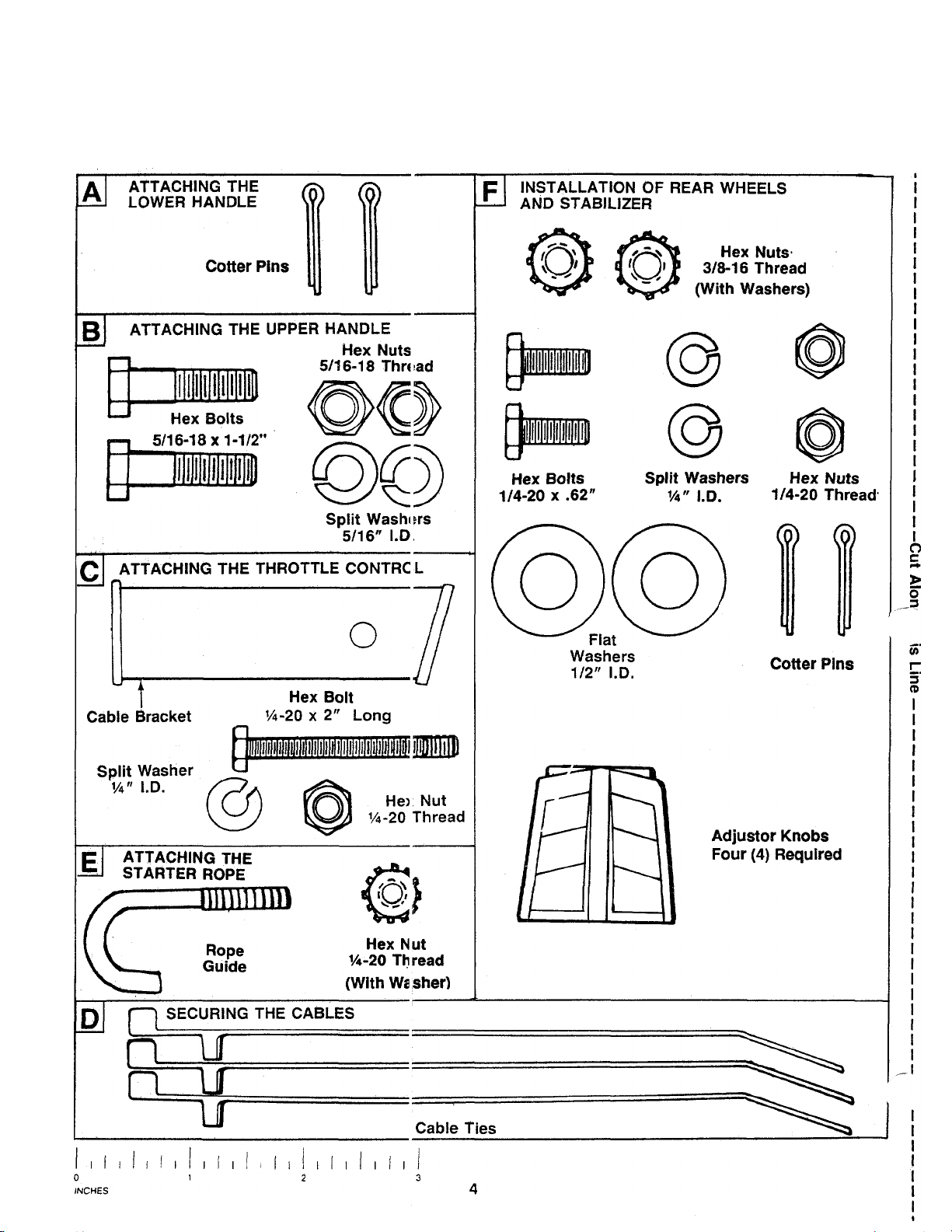
CONTENTS OF HARDWARE PACK
Remove this sheet from your owner’s manual and lay the hardware on the illustration for identification purposes.
After assembly, keep the Slope Gauge which is on the reverse side of this sheet for future use.
(Hardware pack may conta n extra items which are not used on your unit.)
Page 5

IMPORTANT
RULES FOR SAFE OPERATION
THIS SYMBOL POINTS OUT IMPORTANT SAFETY INSTRUCTIONS WHICH, IF NOT FOLLOWED, COULD ENDANGER THE PERSONAL SAFETY
AND/OR PROPERTY OF YOURSELF AND OTHERS, READ AND FOLLOW ALL INSTRUCTIONS IN THIS MANUAL BEFORE AHEMPTING
TO OPERATE YOUR LAWN MOWER. FAILURE TO COMPLY WITH THESE INSTRUCTIONS MAY RESULT IN PERSONAL INJURY. WHEN
YOU SEE THIS SYMBOL-
A
HEED ITS WARNING.
DANGER
AC
Your lawn mower was built to be operated according to the rules for safe operation in this manual. As
with any type of power equipment, carelessness or error on the part of the operator can result In serious
injury. If you violate any of these rules, you may cause serious injury to yourself or others.
A
TRAINING
Read this owner’s guide carefully in its entirety before attempting
to assemble or operate this machine. Be completely familiar with
the controls and the proper use of this machine before operating
it. Keep this manual in a safe place for future and regular reference
and for ordering replacement parts.
2. Your rotary mower is a precision piece of power equipment, not
a plaything. Therefore, exercise extreme caution at ail times.
3. Never allow children to operate a power mower. Only persons well
acquainted with these rules of safe operation should be allowed
to use your mower.
4. Keep the area of operation clear of all persons, particularly small
children and pets. Stop engine when they are in the vicinity of
your mower to help prevent blade contact or thrown object in
jury. Although the area of operation should be completely cleared
of foreign objects, an object may have been overlooked and could
be accidently thrown by the mower in any direction and cause
serious personal injury to the operator or any others allowed in
the area.
PREPARATION
1. Thoroughly inspect the area where the equipment is to be used.
Remove all stones, sticks, wire, bones and other foreign objects
which could be picked up and thrown by the mower in any direc
tion and cause serious personal injury to the operator or any others
allowed in the area.
2. Always wear safety glasses or eye shields during operation or while
performing an adjustment or repair, to protect eyes from foreign
objects that may be thrown from the machine in any direction.
3. Wear sturdy, rough-soled work shoes and close-fitting slacks and
shirts to avoid entanglement in the moving parts. Never operate
a unit in bare feet, sandals, or sneakers.
4. Check the fuel before starting the engine. Gasoline is an extreme
ly flammable fuel. Do not fill the gasoline tank indoors, while the
engine is running, or until engine has been allowed to cool for
two minutes after running. Replace gasoline cap securely and wipe
off any spilled gasoline before starting the engine as it may cause
a fire or explosion,
5. Disengage the self-propelled mechanism or drive clutch on units
so equipped before starting the engine,
6. The blade control handle is a safety device. Never attempt to bypass
its operation. Doing so makes the safety device inoperative and
may result in personal injury through contact with the rotating
blade. The blade control handle must operate easily in both
directions.
7. Never attempt to make a wheel or cutting height adjustment while
the engine is running.
8. Never operate the equipment in wet grass. Always be sure of your
footing. A slip and fall can cause serious personal injury. Keep
a firm hold on the handle and walk, never run. Mow only in daylight
or in good artificial light.
A°
A
For your safety, use the slope gauge included as part of this manual
to measure slopes before operating this unit on a sloped or hilly
area. If the slope is greater than 15“ as shown on the slope gauge,
do not operate this unit on that area or serious injury could result.
OPERATION
1.
Do not change the engine governor settings or overspeed the
engine. Excessive engine speeds are dangerous.
2.
Do not put hands or feet near or under rotating parts. Keep clear
of the discharge opening at all times as the rotating blade can
cause injury.
Stop the blade when crossing gravel drives, walks or roads.
After striking a foreign object, stop the engine, remove the wire
from the spark plug, and thoroughly inspect the mower for any
damage. Repair the damage before restarting and operating the
mower.
5.
If the equipment should start to vibrate abnormally, stop the engine
and check immediately for the cause. Vibration is generally a warn
ing of trouble.
6.
Shut the engine off and wait until the blade comes to a complete
stop before removing the grass catcher or unclogging the chute.
The cutting blade continues to rotate for a few seconds after the
engine is shut off. Never place any part of the body in the blade
area until you are sure the blade has stopped rotating.
7.
Before cleaning, repairing or inspecting, make certain the blade
and all moving parts have slopped. Disconnect the spark plug wire,
and keep the wire away from the spark plug to prevent accidental
starting.
Do not run the engine indoors.
Mow across the face of slopes, never up-and-down. Exercise ex
treme caution when changing direction on slopes. Do not mow
excessively steep slopes. Always be sure of your footing, A slip
and fall can cause serious personal injury.
10,
Never operate mower without proper guards, plates or other safety
protective devices in place.
MAINTENANCE AND STORAGE
1. Check the blade and engine mounting bolts at frequent intervals
for proper tightness.
2. Keep all nuts, bolts, and screws tight to be sure the equipment
is in safe working condition.
3. Never store the equipment with gasoline in the tank inside of a
building where fumes may reach an open flame or spark. Allow
the engine to cool before storing in any enclosure.
4. To reduce fire hazard, keep the engine free of grass, leaves, or
excessive grease.
5. Check the grass catcher bag frequently for wear or deterioration.
For safety protection, replace only with new bag meeting original
equipment specifications.
Page 6

IMPORTANT: This unit is Shipped M^ITHOUT GASOLINE or OIL. After assembly, service engine with
gasoline and oil as im^ructed in the separate engine manual packed with your unit.
NOTE: Reference to right or I ;ft hand side of the mower is observed from the operating position.
ASSEMBLY INSTRUCTIONS
Tools Required for Assembly
(1) Pair of Pliers
(2) 7/16" Wrenches*
(2) 1/2" Wrenches*
(1)9/16" Wrench*
* Or 6" Adjustable Wrenches.
REMOVE CARDBOARD
FIGURE 1.
UNPACKING
1.
Remove the lawn mower from the carton by opening
the top flaps and lifting the unit out. Be careful of the
staples. Make certain all parts and literature have
been removed from the carton before the carton is
discarded.
2. Disconnect and ground the spark plug wire against
the engine. Check beneath the deck for any card
board packaging. Remove if present.
3. Stretch out ail control cables on the floor to rear of
mower. Be careful not to bend or kink the cables at
any time during assembly.
4. Remove page four from this manual and lay the
contents of the hardware pack on the illustration for
identification.
5. The chute deflector on your mower is held in an_
upright position by a pad for shipping purposes onl
This shipping pad must be removed and discarded
before the mower is put into operation. See figure 1.
FIGURE 2.
FIGURE 3.
ATTACHING THE LOWER HANDLE
1. Position lower handle so rope guide mounting hole
and dimple, on handle cross bar, are facing down
wards. See figures.
2. Slip one leg of lower handle onto the pin of one of the
attaching brackets on the mower base. Apply inward
pressure on the other leg of the handle and snap over
the pin of the other attaching bracket. Secure with
cotter pins supplied. See figure 2.
ATTACHING THE UPPER HANDLE
1. Position upper handle assembly so the engine con
trol lever is on top side of the handle and attach to
lower handle with (2) 5/16-18x1 -1 /2" hex head bolts,
5/16" split washers and 5/16-18 nuts. See Fig. 3.
Page 7

=IGURE 4.
THBOTTUE
AHACHING THE THROTTLE CONTROL
The throttle control cable is attached to the engine. Attach
the throttle control to the left side of upper handle as follows
(See Fig. 4).
1 Route the throttie control cable inside the iegs and
beneath the upper bar of the lower handle.
2. Place cable bracket against left side of upper handie,
lining up the hole in the bracket with the bottom hole
in upper handle. Place 1/4" hex bolt through cable
bracket and handle, from the inside to the outside.
3. Place throttle control on the hex bolt (outside of upper
handle), with the throttie iever facing upward. Se
cure with spiit washer hex nut.
r nmNG
FIGURE 5.
BLADE
CONTROL
HANDLE
ATTACHING THE BRAKE CABLE
1. The brake cable is attached to the engine, and has a
"Z" fitting on the loose end. Route the brake cable
below the lower handle. Place end of cable through
the hole in the bracket as shown (See Fig. 5). Be
careful notto bend orkinkthecable at anytime. Push
the plastic fitting until it locks into the hole in the
bracket.
WARNING: Brake cable must be assembled
A
2. Hook the "Z" end of the brake cable into the hole in
SECURING THE CABLES
Secure all cables to the handle as follows.
1. Insert posts on cable ties into holes provided on the
as shown for proper blade brake operation.
the blade control handle from the inside to the
outside as shown (See Fig. 5).
left side of the handle, one on the upper handle and
two on the lower handle. The holes may be either on
the inside or outside of the handles. See figure 6A.
2. Secure the cables with the cable ties. See figure 6B.
3. Trim excess ends of cable ties.
RECOIL STARTER ROPE ASSEMBLY
1. Attach starter rope to lower handle with supplied
rope guide (J-bolt) and 1/4-20 hex keps lock nut as
shown See Figure 7. NOTE: If additional rope is
required to complete assembly, pull back engine
control bail lever on upper handle and hold while
slowly pulling additional rope out of engine as
needed. Place rope guide around starter rope and
through lower handle. Tighten securely with lock nut.
Page 8

1/4-20 Hex Hut
AHACHING THE STABILIZER
1. Attach stabilizer to rear brackets with 1/4-20 x 5,,
hex bolts, 1/4" split washers and 1/4-20 hex nuts.
See figure 8A. Assemble both sides loosely then
tighten securely.
AHACHING THE REAR HEIGHT ADJUSTORS
1. Attach the rear height adjustors to the angled holes
in brackets as shown. See figure 8B. Secure with
3/8-16 hex keps nuts.
NOTE: The adjustors are different - assemble so axle pin
on adjustor is toward rear of mower on both sides as shown.
2. Assemble plastic knobs to wheel height adjustor
levers by pressing on or tapping lightly.
FIGURE 8B.
1/2" Flatwasher
AHACHING THE REAR WHEELS
1. Attach rearwheels to adjusters with 1/2" flatwashers
and cotter pins. See figure 9. Bend ends of cotter
pins to secure.
Page 9

CONTROLS
The blade control handle is located on the upper han
dle of the mower. See figure 10. The blade control han
dle must be depressed in order to operate the unit.
Release the blade control handle to stop the engine and
blade.
A
THROTTLE CONTROL
The throttle control is located on the side of the upper
handle. It Is used to regulate the engine speed.
WARNING: The blade will be rotating
whenever the engine is running.
FIGURE 10.
BLADE CONTROL HANDLE
WARNING
THIS CONTROL MECHANISM IS A
SAFETY DEVICE NEVER ATTEMPT
TO BYPASS IJS OPERATIONS
TO REDUCE THE RISK OF INJURY, DO NOT
OPERATE MOWER UNLESS REAR TRAILING
SHIELD AND THIS GUARD OR ENTIRE
GRASS CATCHER IS IN ITS PROPER PLACE.
A
RECOIL STARTER
The recoil starter handle is attached to the handle. See
figure 10. Stand behind the unit in the operating posi
tion to start the unit.
OPERATION
NOTE: Adjust the cutting height of your mower before
operating. See adjustment section of this manuai.
GAS AND OIL FILL-UP
Service the engine with gasoline and oil as instructed
in the separate engine manual packed with your
mower. Read instructions carefully.
A
WARNING: The throttle control cannot be
used to stop the engine.
WARNING: Never fill fuel tank indoors,
with engine running or until the engine has
been allowed to cool for at least two
minutes after running.
FIGURE 11.
Keep hands and feet away from the chute area on
cutting deck. See figure 11.
The operation of any lawn mower can result in
foreign objects being thrown into the eyes, which
can result in severe eye damage. Always wear
safety glasses or eye shields. We
recommend wide vision safety mask
for over spectacles or standard
safety glasses, available at your
nearest dealer.
TO START ENGINE AND ENGAGE BLADE
1. Attach spark plug wire to spark plug. If unit is
equipped with a rubber boot over the end of the
spark plug wire, make certain the metal loop on
the end of the spark plug wire (inside the rubber
boot) is fastened securely over the metal tip on the
spark plug. See figure 12.
Metal Loop
on Spark
Plug Wire
Rubber Boot
FIGURE 12.
Page 10

2. Open fuel shut-off valve. See figure 13.
FIGURE 13.
3. Move throttle control lever all the way forward.
4. Standing behind the unit, depress the blade con
trol handle and hold it against the upper ha idle
as shown. See figure 14.
5. Grasp the recoil starter handle and pull back r£ .pidly, extending rope fully. Return it slowly to the rope
guide bolt.
6. After engine starts, move throttle control to des ired
engine speed.
NOTE: If any problems are encountered, refer tc the
Trouble Shooting Guide on page 13.
in any direction and cause serious personal injury to
the operator and others.
For the best results, do not cut wet grass because it
tends to stick to the underside of the mower, prevent
ing proper discharge of grass clippings, and could
cause you to slip and fall. New grass, thick grass or
wet grass may require a narrower cut. Blade speed
should be adjusted to the condition of the lawn.
The best mowing pattern is one that allows the clippings
to discharge towards the uncut part of the lawn. This
permits recutting of the clippings to further pulverize
them. When cutting high weeds, discharge towards cut
portion, then recut at right angles to first direction.
For best results, cut off one-third or less of the total
length of the grass. Lawn should be cut in the fall as
long as there is growth.
This mower is designed to be operated at full throttle
to give you the best cut and do the most effective job
of bagging the cut grass.
WARNING: If you strike a foreign object,
stop the engine. Remove wire from spark
A
plug, thoroughly inspect the mower for any
damage, and repair the damage before
restarting and operating the mower. Exten
sive vibration of the mower during opera
tion is an indication of damage. The unit
should be promptly inspected and
repaired.
TO STOP ENGINE AND BLADE
1. Release the blade control handle to stop the
engine and blade.
WARNING: The blade continues to ro ate
for a few seconds after the engine is shut
A
2. Disconnect the spark plug wire and ground it
USING YOUR ROTARY MOWER
Be sure that lawn is clear of stones, sticks, wire, or c ther
objects which could damage lawn mower or engine.
Such objects could be accidently thrown by thé me wer
off.
against the engine to prevent accidental starting
while equipment is unattended.
ADJUSTMENTS
WARNING: Do not at any time make any
adjustment to lawn mower without first
A
CUTTING HEIGHT ADJUSTMENT
An adjusting plate and thumb lever at each wheel posi
tion provides cutting height adjustment. Each adjusting
plate has nine height positions. Height of cut will be
changed when the thumb lever is moved from one hole
to another. Simply depress the lever towards wheel and
move wheel and lever assembly to desired position. All
wheels must be placed in the same relative position.
See figure 15.
FIGURE 15.
stopping engine and disconnecting spark
plug wire.
10
Page 11

THROTTLE CONTROL ADJUSTMENT
If the throttle control needs adjustment or if it has been
replaced, adjust as follows.
1. Remove the screw shown in figure 17. Remove the
cable clamp from the cable.
Push the throttle control lever on the handle all the
2.
way forward to CHOKE position. Make certain the
throttle control lever remains in this position.
Push the control lever on the engine as far toward
3.
the rear of the engine as it will go. Secure the cable
in this position with the cable clamp and screw.
Cable
Clamp
FIGURE 17.
CARBURETOR ADJUSTMENTS
WARNING: If any adjustments are made to
the engine while the engine is running (e.g.
A
Minor carburetor adjustments may be required to
compensate for differences in fuel, temperature,
altitude and load. To adjust carburetor, refer to the
separate engine manual packed with your mower.
NOTE: A dirty air cleaner will cause an engine to run
rough. Be certain air cleaner is clean and attached to
the carburetor before adjusting carburetor. Refer to the
separate engine manual.
carburetor), keep clear of all moving parts.
Be careful of heated surfaces and muffler.
LUBRICATION
WARNING: Always stop engine and
disconnect spark plug wire before clean
A
Blade Control—Lubricate the pivot points on the blade
control handle and the brake cable at least once a
season with light oil. See figure 18. The blade control
must operate freely in both directions. .
ing, lubricating or doing any kind of work
on lawn mower.
Pivot
Point
FIGURE 18.
Chute Deflector—The torsion spring and pivot point
should be lubricated periodically with light oil to pre
vent any rust or binding. Deflector must work freely.
Wheels—Mower may be provided with ball bearing
wheels. Lubricate at least once a season with light oil.
Also, if the wheels are removed for any reason,
lubricate the surface of the axle bolt and the inner sur
face of the wheel with light oil. A 4 oz. plastic bottle
of light oil lubricant is availabie. Order part number
737-0170. Engine oil may also be used.
Engine—Follow engine manual for lubrication in
structions.
Throttle—Periodically lubricate throttle control lever
and throttle wire assembly with a few drops of light oil
for ease of operation.
11
Page 12

MAINTENANCE
WARNING: Be sure to disconnect and
ground the spark plug wire before perf arm
A
NOTE: When tipping the unit, empty the fuei tank and
keep engine spark piug side up.
TROUBLE SHOOTING
Refer to page 13 of this manual for trouble shooting
information.
CUTTING BLADE
When removing the cutting blade for sharpening or
replacement, protect hands by using heavy glovos or
a rag to grasp the cutting blade. Remove the bolt and
bell washer which hold the blade and adapter tci the
engine crankshaft. Remove the blade and adapter from
the crankshaft.
If the blade or blade adapter needs replacing, remove
the two small bolts, lock washers and nuts which hold
the blade to the adapter.
A
When sharpening the blade, follow the original angle
of grind as a guide, it is extremely important that i ?ach
cutting edge receives an equal amount of grindir g to
prevent an unbalanced blade. An unbalanced bladiî will
cause excessive vibration when rotating at high spe eds,
may cause damage to the mower and could break,
causing personal injury.
It is recommended that the blade always be removed
from the adapter for the best test of balance.
The blade can be tested by balancing it on a round : ¡haft
screwdriver. Remove metal from the heavy side until
it balances evenly.
Before reassembling the blade and the blade adc pter
to the unit, lubricate the engine crankshaft and the i iner
surface of the blade adapter with light oil. LubriCc.ting
the bolt holes, bolts and inner surface of the nuts with
light oil is also recommended. A 4 oz. plastic bott e of
light oil lubricant is available. Order part number
737-0170. Engine oil may also be used.
When replacing the blade, be sure to install the biade
with the side of the blade marked “Bottom” (or with
part number) facing the ground when the mower is in
the operating position.
ing any repairs or maintenance.
WARNING: Periodically inspect the blade
adapter for cracks, especially if you s :rike
a foreign object. Replace when necessary.
DECK
The underside of the mower deck should be cleaned
after each use to prevent a buildup of grass clippings,
leaves, dirt or other matter. If this debris is allowed to
accumulate, it will invite rust and corrosion, and may
cause an uneven discharge of grass clippings at the
next cutting.
The deck may be cleaned by tilting the mower and
scraping clean with a suitable tool (make certain the
spark piug wire is disconnected).
ENGINE
Refer to the separate engine manual for engine
maintenance instructions.
Maintain engine oil as instructed in the separate
engine manual packed with your unit. Read and follow
instructions carefully.
Service air cleaner every 25 hours under normal con
ditions. Clean every few hours under extremely dusty
conditions. Poor engine performance and flooding
usually indicates that the air cleaner should be ser
viced. To service the air cleaner, refer to the separate
engine manual packed with your unit.
The spark plug should be cleaned and the gap reset
once a season. Spark plug replacement is recom
mended at the start of each mowing season; check
engine manual for correct plug type and gap
specifications.
Clean the engine regularly with a cloth or brush. Keep
the cooling system (blower housing area) clean to per
mit proper air circulation which is essential to engine
performance and life. Be certain to remove all grass,
dirt and combustible debris from muffler area.
OFF-SEASON STORAGE
The following steps should be taken to prepare lawn
mower for storage.
1. Clean and lubricate mower thoroughly as de
scribed in the lubrication instructions.
2. Refer to engine manual for correct engine storage
instructions.
3. Coat mower’s cutting blade with chassis grease
to prevent rusting.
4. Store mower in a dry, clean area.
Blade Mounting Torque
Center Bolt and Blade Adapter Bolts;
375 in. lb. min., 450 in. lb. max.
To insure safe operation of your unit, all nuts and holts
must be checked periodically for correct tightness.
NOTE: When storing any type of power equipment in
an unventilated or metai storage shed, care should be
taken to rust-proof the equipment. Using a light oil or
silicone, coat the equipment, especially cables and all
moving parts.
12
Page 13

TROUBLE SHOOTING GUIDE
Trouble
Engine fails to start
Engine runs erratic
Engine overheats 1. Engine oil level low.
Occasional skip
(hesitates) at high speed
1. Blade control handle disengaged.
2. Spark plug wire disconnected.
3. Throttle control lever not in CHOKE
or START position.
4. Fuel shut-off valve closed (if so
equipped).
5. Fuel tank empty, or stale fuel.
6. Blocked fuel line.
7. Faulty spark plug,
8. Engine flooded.
1. Unit running in CHOKE or START
position.
2. Spark plug wire loose.
3. Blocked fuel line or stale fuel.
4. Vent in gas cap plugged.
5. Water or dirt in fuel system.
6. Dirty air cleaner.
7. Carburetor out of adjustment.
2. Air flow restricted.
3. Carburetor not adjusted properly.
1. Carburetor idle speed too slow.
2. Spark plug gap too close.
3. Carburetor idle mixture adjustment
improperly set.
Possible Cause(s)
Corrective Action
1. Engage blade control handle.
2. Connect wire to spark plug.
3. Move throttle lever to CHOKE or
START position.
4. Open fuel shut-off valve.
5. Fill tank with clean, fresh gasoline.
6. Clean fuel line.
7. Clean, adjust gap or replace.
8. Remove spark plug, dry the plug, and
crank engine with plug removed and
throttle in off position. Replace spark
plug, connect wire and resume starting
procedures.
1. Move throttle lever to FAST
position.
2. Connect and tighten spark plug wire.
3. Clean fuel line; fill tank with clean,
fresh gasoline.
4. Clear vent.
5. Drain fuel tank. Refill with fresh fuel.
6. Clean air cieaner.f
7. Adjust carburetor.f
1. Fill crankcase with proper oil.
2. Remove blower housing and clean.t
3. Adjust carburetor.!
1. Adjust carburetor.!
2. Adjust gap to .030".
3. Adjust carburetor.!
Idles poorly
Excessive vibration
Mower will not
discharge grass
Uneven cut 1. Wheels not positioned correctly.
tRefer to separate engine manual packed with your unit.
Note: For repairs beyond the minor adjustments listed above, contact your local authorized service dealer.
1. Spark plug fouled, faulty or gap too wide.
2. Carburetor improperly adjusted.
3. Dirty air cleaner.
1. Cutting blade loose or unbalanced.
2. Bent cutting blade.
1. Engine speed too low.
2. Wet grass.
3. Excessively high grass.
2. Dull blade.
1. Reset gap to .030" or replace spark plug.
2. Adjust carburetor.!
3. Clean air cleaner.!
1. Tighten blade and adapter.
Balance blade.
2. Replace blade.
1. Set throttle between 3/4 and full throttle.
2. Do not mow when grass is wet; wait until
later to cut.
3. Mow once at a high cutting height, then
mow again at desired height or make a
narrower cutting swath (1/2 width).
1. Place all four wheels in same
height position.
2. Sharpen or replace blade.
13
Page 14

Page 15

Model A508R
REF
NO. PART NO.
DESCRIPTION
PARTS LIST FOR MODEL A508R ROTARY MOWER
REF.
NO.
PART NO.
DESCRIPTION
1
749-980e*
Lower Handle
27
706-10002
2 749-0756 Upper Handle 28 734-1661
3 747-0748
4
746-0761 Throttle Control
710-0501 Hex Bolt 1/4-20 X 2.00" Lg.*
5
17174
6
712-0287
7
89736-0329
746-0553
10 747-0779
11 712-0324
12 710-0442 Hex Bolt 5/16-18 X 1.50 Lg." 36
712-0267
13
14
736-0119
15 726-0240 Cable Tie 39
714-0474 Cotter Pin 1/8 X 3/4" Lg.*
16
17
706-14267-01-10 22"DeckAss'y 41
18 706-106d5-16 Engine Mtg. Bolt (Special)
19 731-1179
20 706-10698-00-05 Hinge Bracket 44
21
710-0258
22
706-10961-00-09
'23
706-10960-00-09 Handle Bracket - LH 47
24
710-0258 Hex Bolt 1/4-20 X .62" Lg.*
25 706-13798
26 706-15499
706-15498
Engine Control Lever 29 712-0431
30 706-10127-02
-
706-10128-02
Cable Mounting Bracket 31 750-0796
Hex Nut 1/4-20 Thd*
L-Wash. 1/4" I.D.*
32
734-1655 8" Wheel Ass'y
33 748-0485
Control Cable - 36"
Rope Guide (J-Bolt) 34 742-0522
Hex L-Nut 1/4-20 Thd 35
710-0757
736-0439 Bell-Wash. .460 I.D.
Hex Nut 5/16-18 Thd*
L-Wash. 5/16 I.D.*
37
710-1055
38 736-0169 L-Wash. 3/8" I.D.*
712-0241
40 706-15492-01-90 Chute Deflector
706-10115-03-05 Hinge Pin
42
706-10116 Retainer
Rear Flap
43 706-10113-00-90 Adaptor Plate
706-15615-01
Hex Bolt 1/4-20 X .62" Lg.*
Handle Bracket - RH 46
45 710-0167
706-13797-01-10
710-0216
48 712-0430
Stabilizer Bar
Adjustor Ass'y - Left Rear
49 706-13913 Casing Clamp
50 706-14697-10 Scr. - Casing Clamp
Adjustor Ass'y - Right Rear
FI-Wash. 1/2" I.D.*
16" Steel Spoke Wheel
Hex L-Nut 3/8-16 Thd
Adjustor Ass'y - Right Front
Adjustor Ass'y - Left Front
Wheel Spacer
Blade Adaptor Kit (Incl. 35,36,37,
38 and 39)
22" Blade
Blade Bolt (Special)
Hex Bolt 3/8-24 X 1.00 Lg.
Hex Nut 3/8-24 Thd.
Spring
Carriage Bolt 1/4-20 x .50 Lg.*
Brackef(Right & Left)
Hex Bolt 3/8-16x3/4" Lg.*
Hex L-Nut 3/8-16 Thd.
*For faster service obtain standard nuts, bolts and washers locally.
If these items cannot be obtained locally, order by part number and
size as shown on parts list.
15
Page 16

PARTS INFORMATION
POWER EQUIPMENT PARTS AND SERVICE BRIGGS AND STRATTON, TECUMSEH AND PEERLESS PARTS AND
Parts and service are available through the authorized service firms lis ted SERVICE
below/. All orders should specify the model number of your unit, part Briggs & Stratton, Tecumseh and Peerless parts and service should be
numbers, description of parts and the quantity of each part requit sd. handled by your nearest authorized engine service firm. Check the yellow
NOTE: If any parts are found to be missing or defective upon assembly of this unit, write to advise the factory so that
immediate replacement can be made.
ARKANSAS NORTH LITTLE ROCK
Sutton’s Lawn Mower Shop
CALIFORNIA PORTERVILLE
Billious ........................................... 75 North D Street
COLORADO
Spitzer Industrial Products Co.
FLORIDA JACKSONVILLE
Radco Distributors
Small Eng. Dist............................... 7995 W. 26th Court . . . ,33( 16
ILLINOIS LYONS
Keen Edge Co
INDIANA ELKHART
Parts & Sales Inc
IOWA DUBUQUE
Power Lawn & Garden Equip.. . . 2551 J.F. Kennedy.........52C01
MARYLAND BELTSVILLE
Center Supply Co...................■. . . . 6802 Industrial Dr.
MASSACHUSETTS SPRINGFIELD
Morton B. Collins Co
MICHIGAN MOUNT CLEMENS
Power Equipment Dist
MINNESOTA PLYMOUTH
Hance Distributing Inc.................... 12795 16th Ave. North .55^41
MISSOURI EARTH CITY
Oscar Wilson Engine & Parts ... 4159 Shoreline Dr
Automotive Equip. Service
NEW YORK CARTHAGE
Gamble Dist., Inc............................... West End Ave.
.........................
..................................
...........................
...........
5301 Roundtop Drive
Box 368, Rt. 4
DENVER
. 6601 N.
Washington St
4909 Victor St.
Box 5459
HIALEAH
8615 Ogden Ave
2101 Industrial Pkwy.
Box 277
#208
...............................
......................
............... 340 Hubbard
...............
300 Birnie Ave
KANSAS CITY
3117 Holmes St
Box 389
.................
.................
........................
............
..........................
...................
..................
.................
.............
..........................
72-17
. 93: 57
80: 29
32: 07
60J34
46E16
207 05
01107
48C43
63C45
64109
13619
pages of your telephone directory under the listing Engines—Gasoline,
Briggs & Stratton or Tecumseh Lauson.
NORTH CAROLINA
Dixie Sales Company...................
OHIO
Stebe’s Mid-State Mower Supply
Bleckrie, Inc
National Central
Burton Supply Co
PENNSYLVANIA
EECO Inc.......................................
Bluemont Co
Frank Roberts & Sons
Scranton Auto Ignition Co
TENNESSEE
Ace Distributors..............................
Chilton Air Cooled Engine..............
TEXAS
Marr Brothers, Inc
UTAH
Powered Products
VIRGINIA
RBI Corp
WASHINGTON
Equip. Northwest
WISCONSIN
Wisconsin Magneto Inc
PUERTO RICO
Island Distribution Center
...................................
.............................
..........................
..................................
...................
..............
..........................
........................
........................................
...........................
..................
..............
BROWNS SUMMIT
5920 Summit Ave
CARROLL
Box 366, 71 High St
CLEVELAND
7900 Lorain Ave
WADSWORTH
687 Seville Rd
YOUNGSTOWN
1301 Logan Ave.
Box 929
HARRISBURG
4021 N. 6th St
PITTSBURGH
11101 Frankstown Rd. .15235
PUNXSUTAWNEY
R.D. 2
SCRANTON
1133-35 Wyoming Ave. .18509
KNOXVILLE
2103 Magnolia................37917
NASHVILLE
319 4th Ave. S................37210
DALLAS
423 E. Jefferson
SALT LAKE CITY
1661 N. Beck St
ASHLAND
101 Cedar Ridge Dr. . . .23005
SEATTLE
1410 14th Ave
MILWAUKEE
4727 N. Teutonia St
RAMEY
102 N. St
........................
............................
...........
___
.............
...............
................
.............
.............
................
___
.......................
27214
43112
44102
44281
44501
17110
15767
75203
84116
98122
53209
.00604
WARRANTY PARTS AND SERVICE POLICY (0689)
The purpose of warranty is to protect the customer from defecs in workmanship and materials, defects which are NOT detected at the time
of manufacture. It does not provide for the unlimited and unrest noted replacement of parts. Use and maintenance are the responsibility of the
customer. The manufacturer cannot assume responsibility for ccnditions over which it has no control. Simply put, if it's the manufacturer’s fault,
it’s the manufacturer’s responsibility; if it’s the customer’s faul , it’s the customer’s responsibility.
CLAIMS AGAINST THE MANUFACTURER’S WARRANTY
INCLUDES;
1. Replacement of Missing Parts on new equipment.
2. Replacement of Defective Parts within the warranty peric d.
3. Repair of Defects within the warranty period.
All claims MUST be substantiated with the following
information:
1. Model Number, Serial Number and/or Date Code of unit in
volved.
2. Date unit was purchased.
3. Date of Failure.
4. Nature of Failure.
MTD PRODUCTS INC P.O. EOX 360900 CLEVELAND, OHIO 44136
 Loading...