

Page 1

.50
ASSEMBLY
OPERATION
MAINTENANCE
PARTS LIST
IMPORTANT:
Read Safety Rules
and Instructions
PRINTED IN U.S.A.
MODEL NUMBER
110-530A
22"
HI-WHEEL
ROTARY
MOWER
FORM NO. 770-0207
Page 2

INDEX
Safe Operation Practices
Assembiy Instructions
Operation Instructions......................................................5
Adjustments......................................................................6
Lubrication........................................................................7
Maintenance................................................................... 8
r
.................................................
.....................................................
♦
♦
♦
♦
♦
♦
♦
♦
♦
♦
♦
♦
For one year from the date of original retail purchase, MTD PRODUCTS INC will either
repair or replace, at its option, free of charge, F.O.B. factory or authorized service firm,
any part or parts found to be defective in material or workmanship. Transportation charges
for any parts submitted for replacement under this warranty must be paid by the purchaser
unless such return is requested by MTD PRODUCTS INC.
This warranty will not apply to any part which has become inoperative due to misuse,
excessive use, accident, neglect, improper maintenance, alterations, or unless the unit
has been operated and maintained in accordance with the instructions furnished. This
warranty does not apply to the engine, motor, battery, battery charger or component parts
thereof. Please refer to the applicable manufacturer’s warranty on these items.
This warranty will not apply where the unit has been used commercially.
Warranty service is available through your local authorized service dealer or distributor. If
you do not know the dealer or distributor in your area, please write to the Customer Service
Department of MTD.
LIMITED WARRANTY
3
4
Using Your Rotary Mower
Off-Season Storage...........................................................9
Exploded Parts View
Repair Parts List
Parts Information
...................................................
...........................................
................................................
.........................................
9
14, 16, 18
15,17,19
Back Cover
♦
♦
♦
♦
♦
♦
♦
♦
♦
♦
♦
♦
♦
♦
♦
♦
♦
The equipment which you have just purchased does not have a spark arrester. If this equipment is used on
any forest covered land, brush covered land, or grass covered unimproved land in the State of California,
before using on such land, the California law requires that a spark arrester be provided, in addition, spark
arrester is required by law to be in effective working order. The spark arrester must be attached to the
exhaust system and comply with Section 4442 of the California Public Resources Code.
The return of a complete unit will not be accepted by the factory unless prior written
permission has been extended by MTD.
This warrany gives you specific legal rights. You may also have other rights which vary
from state to state.
WARNING TO PURCHASERS
OF INTERNAL COMBUSTION ENGINE EQUIPPED
MACHINERY OR DEVICES IN THE STATE OF CALIFORNIA
♦
♦
♦
♦
>
Page 3

IMPORTANT
It is suggested that this manual be read in its entirety before attempting to assemble or operate. Keep this
manual in a safe place for future reference and for ordering repiacement parts.
This unit is shipped WITHOUT GASOLINE or OIL. After assembly, see operating section of this manuai for
proper fuel and amount.
Your rotary mower is a precision piece of power equipment, not a plaything. Therefore exercise extreme
caution at all times.
SAFE OPERATION PRACTICES FOR WALK-BEHIND MOWERS
TRAINING
1. Read the Operating and Service Owner’s
Manual carefully. Be thoroughly familiar with
the controls and the proper use of the equip
ment.
2. Never allow children to operate a power
mower. Only persons well acquainted with
these rules of safe operation should be allow
ed to use your mower.
3. Keep the area of operation clear of all per
sons, particularly small children and pets.
Stop engine when they are in the vicinity of
your mower. Although the area of operation
should be completely cleared of foreign ob
jects, a small object may have been overlook
ed and could be accidently thrown by the
mower in any direction.
PREPARATION
1. Thoroughly inspect the area where the equip
ment is to be used and remove all stones,
sticks, wire, bones and other foreign objects
which could be picked up and thrown by the
mower in any direction.
2. Do not operate equipment when barefoot or
wearing open sandals. Always wear substan
tial footwear.
3. Do not wear loose fitting clothing that could
get caught on the mower.
4. Check the fuel before starting the engine. Do
not fill the gasoline tank indoors, when the
engine is running, or while the engine is still
hot. Wipe off any spilled gasoline before start
ing the engine.
5. Disengage the self-propelled mechanism or
drive clutch on units so equipped before start
ing the engine.
6. Never attempt to make a wheel or cutting
height adjustment while the engine is run
ning.
7. Mow only in daylight or in good artificial light.
8. Never operate the equipment in wet grass.
Always be sure of your footing; keep a firm
hold on the handle and walk, never run.
OPERATION
1. Do not change the engine governor settings
or overspeed the engine. Excessive engine
speeds are dangerous.
2. Do not put hands or feet near or under rotating
parts. Keep clear of the discharge opening at
all times.
3. Stop the blade(s) when crossing gravel drive,
walks or roads.
4. After striking a foreign object, stop the
engine, remove the wire from the spark plug.
thoroughly inspect the mower for any
damage, and repair the damage before restart
ing and operating the mower.
5. If the equipment should start to vibrate abnor
mally, stop the engine and check immediately
for the cause. Vibration is generally a warning
of trouble.
6. Stop the engine whenever you leave the
mower, before cleaning the mower housing,
and when making any repairs or inspections.
7. When cleaning, repairing or inspecting, make
certain the blade and all moving parts have
stopped. Disconnect the spark plug wire, and
keep the wire away from the plug to prevent
accidental starting.
8. Before attempting to unctog the mower or
discharge chute, stop the engine and be sure
the blade(s) have stopped completely. Discon
nect the spark plug wire and keep the wire
away from the plug to prevent accidental start
ing.
9. Do not run the engine indoors.
10. Shut the engine off and wait until the blade
comes to a complete stop before removing
the grass catcher or unclogging chute.
11. Mow across the face of slopes, never up-anddown. Exercise extreme caution when chang
ing direction on slopes. Do not mow ex
cessively steep slopes.
12. Always disconnect electric mowers (line
operated) before cleaning, repairing or ad
justing.
13. Never operate mower without proper guards,
plates or other safety protective devices in
place.
14. Keep washout ports and other mower-housing
service openings closed when mowing.
MAINTENANCE AND STORAGE
1. Check the blade and engine mounting bolts at
frequent intervals for proper tightness.
2. Keep all nuts, bolts, and screws tight to be
sure the equipment is in safe working condi
tion.
3. Never store the equipment with gasoline in
the tank inside of a building where fumes may
reach an open flame or spark. Allow the
engine to cool before storing in any
enclosure.
4. To reduce fire hazard, keep the engine free of
grass, leaves, or excessive grease.
5. Check the grass catcher bag frequently for
wear or deterioration. For safety protection
replace only with new bag meeting original
equipment specifications.
Page 4
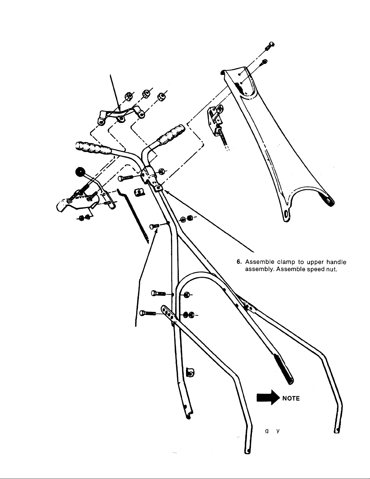
ASSEMBLY INSTRUCTIONS
NOTE: Follow instructions in numerical order.
7. Assemble lockout bracket
as shown.
8. Fasten lockout lever to
lockout bracket assembly
with hex screw, lock
washer and hex nut.
1. Assemble throttle
control to handle
panel.
11. Slip hand grips on
the upper end of
each handle. They
will slip on more
easily if you first
soak them in
warm soapy wa
ter.
9. Blade Engagement Assembly,
a. Remove blade spindle cover by
removing three screws.
Move brake lever to rear posi
b.
tion so belt is slack.
Insert ferrule into blade bracket
c.
assembly from the left.
d.
Screw rod into ferrule.
Assemble control handle to
e.
control rod as shown.
f.
Adjust control rod. A slight
pressure should be needed to
operate lockout lever. Too
much pressure can break lever
assembly or control rod. Read
just control rod if pressure is
too great.
Replace blade spindle cover.
g-
3. Assemble two upper handles. Use this bolt
only.
5. Position upper handle assembly on lower han
dle. Adjust handle supports as desired.
Fasten upper handle assembly and handle
supports to lower handle.
2. Assemble lower handle to mower. Secure
throttle control wire to lower handle with
cable tie. Cut off end of tie.
4. Assemble two handle supports to mower.
12. Check ALL nuts and bolts for correct
tightness.
10. Assemble handle
panel to handle.
It may be necessary to
bend the ends of the
lower handle inward
slightly to assure a
snug fit against the
deck mounting area.
Page 5
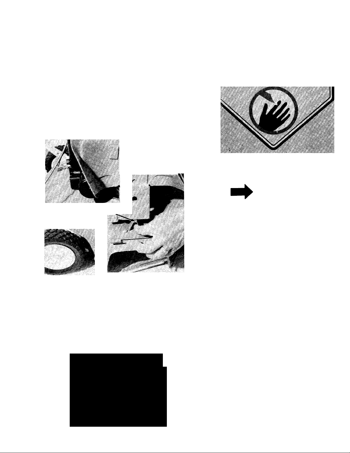
CAUTION
Please note that the chute deflector
on your mower is in an upright posi
tion. It is held in that position by a
shipping block. This block is used
for shipping purposes only. It must
be removed and discarded before
your mower is put into operation.
See figure 1.
mmmm
KEEP HANDS and FEET AWAY
Shipping Block
To Be Removed
FIGURE 1.
OPERATION
Chute Deflector
FIGURE 2.
Keep hands and feet away from the chute area on
cutting deck. See figure 2.
NOTE
For shipping purposes your mower
is set with the wheels in a low cut
ting height position. For best
results raise the cutting position un
til it is determined which height is
best for your lawn. See adjustment
section.
1. Before starting engine, check lubrication sec
tion.
2. Check lockout control handle for proper
operation. If too great a pressure is needed to
operate this control, damage can be done to
the mechanism and the rod. Readjust so only
slight pressure is needed to operate the blade
engaging control. See assembly instructions
Step 9.
3. FILL SUMP WITH OIL using a high quality
detergent oil classified “For Service SC, SD,
SE or MS”. Nothing should be added to the
recommended oil.
A\
CAUTION
DO NOT OPERATE
MOWER UNLESS
GUARD OR ENTIRE
GRASS CATCHER IS
IN ITS PROPER PLACE.
SUMMER
(Above 40° F.)
Use SAE 30
If not available,
Use SAE 10W-30
or
SAE 10W-40
DIRECTIONS; Place the engine level. Remove oil
filler plug. FILL THE OIL SUMP TO POINT OF
OVERFLOW. Pour slowly. Capacity pints.
Use SAE 5W-20 or SAE 5W-30
Use SAE 10W or SAE 10W-30
WINTER
(Under 40° F.)
If not available,
Page 6

4. FILL FUEL TANK using clean, fresh, lead-free
or leaded “regular” grade automotive
gasoline. Fill tank completely!
DO NOT MIX OIL WITH GASOLINE.
TO STOP ENGINE
The engine is stopped by moving the throttie con
trol lever to “STOP” position.
5. Move control handle to “OFF” position.
6. Move throttle control lever to “CHOKE” posi
tion.
7. Crank engine. Move throttle control to
“FAST” position as soon as engine fires. Use
choke as needed to keep engine running dur
ing warm up period.
8. Put blade into motion by moving blade control
handle to “ON” position.
To engage the blade with the engine run
ning. ..
a. Move the throttie control lever to “FAST”
position.
b. Engage the blade engagement handle
SLOWLY.
c. Adjust engine speed.
9. A brief break-in period is essential to insure
maximum engine and mower life. This con
sists of running the engine at haif speed for a
period of time required to use one tank of
gasoline. It is also recommended to change
crankcase oil after the first five hours of
operation or as operating conditions dictate.
Always check oil before operating the mower.
BE SURE CRANKCASE IS FULL.
10. Proper lubrication must be maintained at ail
times.
11. Appropriate clothing should be worn when
cutting brush or heavy weeds. Safety shoes
and safety glasses are highly recommended.
ADJUSTMENTS
CAUTION
A
Do not at any time make any adjust
ment to lawn mower without first
stopping engine and disconnecting
spark piug wire.
CONTROL ROD ADJUSTMENT
Control rod adjustments are made as shown
under assembly instructions Step 9.
HANDLE ADJUSTMENT
Handles may be adjusted by changing the posi
tion of the lower support mounting holes. When
this change is made, it may also be necessary to
check the adjustment of control rod. See Step 9
under assembly instructions.
CUTTING HEIGHT
Cutting height adjustment is made by removing
and moving axle bolts to the desired positions. All
axle bolts must be mounted in the same reiative
position to the deck. When wheels are mounted to
the deck, the belleville washers must be assembl
ed with the cupped side towards the deck. This is
necessary to prevent the axle bolts from loosen
ing.
12. Be sure that lawn is ciear of stones, sticks,
wire, or other objects which could damage
lawn mower or engine. For best results and to
insure more even grass distribution, do not
mow when lawn is excessively wet.
IMPORTANT
After striking a foreign object, stop
the engine. Remove wire from spark
plug, thoroughly inspect the mower
for any damage, and repair the
damage before restarting and
operating the mower.
THROTTLE
if adjustment becomes necessary, the throttle
control wire assembiy can be reset as follows:
1. Loosen, but do not remove, screw securing
throttie control wire assembiy at engine. See
figure 3.
2. Move throttle control lever on handle to
“CHOKE” position.
3. Move lever, to which control wire is fastened
at engine, to full open position. Retighten
screw to secure throttle control wire
assembly.
Page 7

FIGURE 3.
To check adjustment, move engine control from
SLOW to FAST speed. If engine tends to stall or
die out, it usually indicates that the mixture is
slightly lean. It may be necessary to open the nee
dle valve slightly to provide a richer mixture. This
richer mixture may cause a slight unevenness in
idling.
Throttle
Control Wire
Screw On ^
Engine
LUBRICATION
IMPORTANT
I WARNING {
If any adjustments are made to the
engine while the engine is running
(e.g. carburetor), disengage all
clutches and blades. Keep clear of
all moving parts and be careful of
heated surfaces and muffler.
CARBURETOR ADJUSTMENTS (See figure 4.)
Minor carburetor adjustment may be required to
compensate for differences in fuel, temperature,
altitude and load.
Initiai Adjustment:
Turn needle valve clockwise to close it. Then open
2 turns. This initial adjustment will permit the
engine to be started and warmed up before mak
ing final adjustment.
Final Adjustment:
With engine running at normal operating speed
(approximately 3000 RPM without load), turn nee
dle valve clockwise until engine starts to lose
speed (lean mixture). Then slowly turn needle
valve counterclockwise past the point of
smoothest operation, until engine just begins to
run unevenly. This mixture will give best perfor
mance under load.
Always stop engine and disconnect
spark plug wire before cleaning,
lubricating or doing any kind of work
on lawn mower.
Wheels—Unit is provided with ball bearing
wheels. Lubricate at least once a season with light
oil.
Protective Shield—The pivot points on the protec
tive shield should be lubricated periodically with
light oil to prevent any rust or binding.
Chute Deflector—The torsion spring and pivot
point should be lubricated periodically with light
oil to prevent any rust or binding. Deflector must
work freely.
Engine—Follow engine manaul for lubrication in
structions. Check oil level before each use.
Throttle—Periodically lubricate throttle control
lever and throttle wire assembly with a few drops
of light oil (SAE No. 10 or 20) for ease of operation.
Friction point between idler bracket assembly
(Ref. No. 18 on page 16) and deck should be greas
ed once each season with a multi-purpose grease.
Blade Spindle Assembly—The blade spindle
assembly is equipped with a grease fitting. Use
grass discharge chute for access to the fitting
located under the deck. Use multi-purpose grease.
Lubricate PRIOR to initial use and every 25 hours
thereafter.
Page 8

MAINTENANCE
CUTTING BLADE
The blade may easily be removed for grinding or
replacement as follows:
1. Remove bolt and lock washer holding blade
and blade adapter to blade spindle.
2. Remove blade and blade adapter from blade
spindle.
3. Remove two bolts, lock washers and nuts
holding blade to blade adapter (if necessary).
When sharpening blade, follow the original angle
of grind as a guide. It is extremely important that
each cutting edge receives an equal amount of
grinding to prevent an unbalanced blade. An un
balanced blade will cause excessive vibration
when rotating at high speeds and may cause
damage to the mower.
To insure safe operation of your unit, ALL nuts
and bolts must be checked periodically for correct
tightness.
DECK
The underside of mower deck should be cleaned
after each period of use as grass clippings, leaves,
dirt and other matter will accumulate. This ac
cumulation of grass clippings, etc., is undesirable
as it will invite rust and corrosion and may cause
an uneven discharge of grass clippings at the next
cutting.
The deck may be cleaned by tilting the mower for
ward or on its side and scraping clean with a
suitable tool or by washing with a stream of water
from a garden hose.
CAUTION
A
Do not direct the stream of water at
a hot engine as damage to the
engine may result.
ENGINE OIL
Check Oil Level before starting engine and
after every 5 hours of operation or each period of
use.
ADD oil as necessary to keep level FULL TO
POINT OF OVERFLOWING.
Before removing oil fill plug, clean area around
plug to prevent dirt from entering oil fill hole.
Engine should be in a level position when check
ing oil.
Change Oil after first 5 hours of operation.
Thereafter change every 25 hours. Change oil
while engine is warm. Oil may be drained from oil
fill hole by tipping unit on its side. Oil capacity
pints. See figure 5.
AIR CLEANER
Clean Air Cleaner and re-oil element every 25
hours under normal conditions. Clean every few
hours under extremely dusty conditions. Poor
engine performance and flooding usually in
dicates that the air cleaner should be serviced.
See figure 6.
1. Remove screw.
2. Remove air cleaner carefully to prevent dirt
from entering carburetor.
3. Take air cleaner apart and clean.
a. WASH foam element in kerosene or a liq
uid detergent and water to remove dirt.
b. DRY foam completely by wrapping and
squeezing in a cloth.
c. SOAK foam with engine oil. Squeeze to
distribute and remove excess oil.
4. Reassemble parts and fasten to carburetor.
Assemble
Stud O"® o* These ^
Screen
Low Points^^:’^^
Towards,
Narrow
Edge of
Element
Assemble Element So
Lip Extends Over Edge
of Air Cleaner Body
Lip Will Form
Protective Seal
When Cover Is
Assembled
FIGURES.
SPARK PLUG
The spark plug gap should be cleaned (see figure
7) and reset to a 0.030-inch clearance once a
season (see figure 8). Spark plug replacement is
recommended at the start of each mowing
season; check engine parts list for correct plug
type.
Page 9

FIGURE 7.
Clean
Electrode
8. Work belt to front and mount on blade spindle
pulley. Replace front belt guard.
9. Replace brake leverassembly.
10. Slip belt on idler pulley between pulley and
belt bracket.
11. Replace blade tension spring.
12. Move blade lock out handle to “ON” position.
13. Position belt bracket on idler pulley to clear
the tightened beit. Secure belt bracket in posi
tion. See drawing on page 10.
14. Replace blade spindle cover.
NOTE
To insure safe operation of your
unit, ALL nuts and bolts must be
checked periodically for correct
tightness.
USING YOUR ROTARY
.030"
eeler Gauge
Spark
Plug
FIGURE 8.
NOTE
Whenever the spark plug is removed
for cleaning, it is advisable to
replace the spark plug gasket with a
new gasket.
BELT REPLACEMENT
Belt replacement may be made as follows:
1. Remove blade spindle cover.
2. Remove front belt guard.
3. Remove blade tension spring.
4. Loosen belt on bracket of idler bearing
assembly.
5. Remove bracket leverassembly.
6. Remove damaged or worn belt.
7. Place new belt on engine pulley. Do not bend
belt guard pins. Beit should be inside of pins.
MOWER
For the best results do not cut wet grass because
it tends to stick to the underside of the mower,
thus preventing proper discharge of grass clip
pings. If wet grass must be cut, reduce walking
speed to hélp distribute the clippings more effec
tively.
New grass should be treated as wet grass, other
wise a normal walking speed is about the right
pace for efficient mowing.
The best mowing pattern is one that allows the
clippings to discharge towards the uncut part of
the lawn. This permits recutting of the clippings
to further pulverize them. When cutting high
weeds, discharge towards cut portion, then recut
at right angles to first direction.
Lawn should be cut in the fall as long as there is
growth.
OFF SEASON STORAGE
The following steps should be taken to prepare
lawn mower for storage.
1. Clean and lubricate mower thoroughly as
described in the lubrication instructions.
2. Refer to Engine Manual for correct engine
storage instructions.
3. Coat mower’s cutting blade with chassis
grease to prevent rusting.
4. Place blocks under deck to raise tires clear of
floor.
' 5. Store mower in a dry, clean area.
Page 10

Brake Shoe 754-0647
BLADE IDLER BRACKET ASSEMBLY DETAIL
Rivet 728-0649
Idler Bracket Assembly 12278
BELT WEAR
Belt clips improperly positioned will cause
premature belt wear. The belt clip must complete
ly clear the belt when the belt is tightened. It
should also assist in freeing the belt from the
blade spindle pulley when the belt is loose. This
may be checked by removing the blade spindle
cover.
Idler Bearing 756-0199
Hex Lock Nut
712-0262
Belt Clip
04563
10
Page 11

11
Page 12

NOTE
The manufacturer DOES NOT recommend the use
of any accessory on this Rotary Mower other than
those manufactured by the mower manufacturer.
GRASS CATCHER Model No. 190-003A is available as optional equip
ment for the mowers shown in this manual.
I WARNING {
1. The mower should not be operated without the entire grass catcher
or chute deflector in place.
2. The mower should not be operated without the protective shield on
the rear of the deck in place.
NOTE:
Under normal usage bag material is subject to wear and should be
checked periodically. Be sure any replacement bag complies with the
mower manufacturer’s recommendations.
For replacement bags, use only factory authorized replacement bag No.
764-0176.
12
Page 13

110-530A
If YOU WRITE TO US ABOUT THIS ARTICU
OR IF YOU ORDER REPLACEMENT PARTS AL
WAYS MENTION THIS MODEL S SERIAL NO
MODEL
14
Page 14

PARTS LIST FOR MODEL 110-530A
REF.
NO.
1
2 726-0188 Cable Tie
3 07861
4 710-0136
5 08376
712-0526
6
7 712-0107 Hex Center L-Nut i/4-20 Thd.
08378
8
09354
9
720-0157
10
08373 Lockout Lever Ass’y. with
12
13 711-0180
14 736-0108 FI-Wash. .510 I.D. X .750
712-0117
15
712-0107
16
17
710-0606 Hex Bolt 1/4-20 X 1.50" Lg.*
18 710-0606 Hex Bolt 1/4-20 X 1.50" Lg.*
712-0107
19
08327
20
21 712-0181
22 738-0234
09372
23
24
710-0412
25 711-0179
26 710-0209
27 09362
28 712-0107
29 710-0102
30 08328
31
710-0158
32
714-0365
33 746-0171
34 11815
35 710-0227
36 710-0192
37
08325 —462
PART
NO.
—
COLOR
CODE
DESCRIPTION
Engine
Clamp Bracket
Hex Bolt 1/4-20 X 1.75" Lg.*
Lockout Brkt. Ass’ySpeed Nut #10-24
Clamp Bracket
Upper Handle (2-Req’d)
Grip
Plastic Ball
Control Rod
O.D.
Hex Cent. L-Nut V4-28 Thd.
Hex Center L-Nut V4-20 Thd.
Hex Center L-Nut V4-20 Thd.
Lower Handle Support—L.H.
Hex Top L-Nut 3/8-16 Thd.
Shid. Bolt .500" Dia. x .295
Pivot Bracket
Hex Bolt 1/4-28 X .75" Lg. Gr.
O
Adjustable Ferrule
Hex Sems Bolt 3/8-16 x .62"
Lg.
Lower Handle
Hex Center L-Nut V4-20 Thd.
Hex Bolt 1/4-20 x 2.50" Lg.*
Lower Handle Support—R.H
Hex Bolt 5/16-24 x 1.25"
#6 Hi-Pro Key 5/32 x 5/8 Dia.
Throttle
—462 Control Panel
Hex Wash. Hd. AB-Tapp Scr.
#8 X .38" Lg.
Truss Mach. Scr. #10-24 x .38
Belt Trap Ass’y. i
NEW
PART
*For faster service obtain standard nuts, bolts and washers
locally. If these items cannot be obtained locally, order by
part number and size as shown on parts list.
When ordering parts, if color or finish is important use the ap
propriate color code shown above (e.g. Red Flake
Finish —11815 (462).)
NOTE: The engine is not under warranty by
the mower manufacturer ... If repairs or
service is needed on the engine, please
contact your nearest author-
ized engine service outlet. Find It Fast
Check the “Yellow Pages” of In The
your telephone book under Y^ow Pages
“Engines—Gasoline.”
-------
(462—Red Flake)
-
This instruction manual covers various models
and all specifications shown do not neces
sarily apply to your model. Specifications sub
ject to change without notice or obligation.
‘NOTE
15
Page 15

110-530A
IF YOU WRITE TO US ABOUT THIS ARTICLE
OR IF YOU ORDER REPLACEMENT PARTS AL
WAYS MENTION THIS MODEL & SERIAL NO
MODEL
16
Page 16

PARTS LIST FOR MODEL 110-530A
REF.
NO.
11
21
PART
1
09373 Control Rod
2 712-0262
3
04563
4
736-0300
NO.
COLOR 1
CODE
DESCRIPTION
Hex Ins. Jam Nut 3/8-24 Thd.
Belt Clip
FI-Wash.
5 756-0199 Flat Idler with Flange
6 12581
8 736-0170
—462
Frame Ass’y.
Special L’Wash. 5/16" Scr.
9 07386 FI-Wash. .406" I.D. x 1.25"
O.D. X .164
10 736-0169 L-Wash. 3/8" Scr.*
710-0152
Hex Scr. 3/8-24 x 1.00" Lg.
H.T.
14
712-0181 Hex Top L-Nut 3/8-16 Thd.
15 08324 —462
16
736-0329 L-Wash. 1/4" Scr.*
17
712-0287
18
12278
Belt Guard
Hex Nut 1/4-20 Thd.*
Idler Brkt. Ass’y- w/Brake
Shoe
19
09925 Sheave Ass’y.—4" Dia.
(Blade Spindle)
20 736-0921
L-Wash. 1/2" Scr.*
712-0200 Hex Ins. Nut 1/2-20 Thd.
22 09371
23
736-0463 FI-Wash. .296 I.D. x .62"
Brake Lever
O.D. X .059
24
738-0234
25
754-0109 “V”-Belt 1/2" X 43" Lg.
26
732-0158 Blade Tension Spring
27
756-0206
28
712-0123
29
726-0111 Push Cap
Shoulder Bolt .500" Dia.
X .295
Engine Pulley 4.00" O.D.
Hex Nut 5/16-24 Thd.*
NEW
PART
'For faster service obtain standard nuts, bolts and washers
locally. If these items cannot be obtained locally, order by
part number and size as shown on parts list.
(462—Red Flake)
When ordering parts, if color or finish is important use the ap
propriate color code shown above (e.g. Red Flake
Finish—11815(462).)
The engine is not under warranty by the mower manufacturer. If repairs or service is needed on the
engine, please contact your nearest authorized engine service outlet. Check the “Yellow Pages” of
your telephone book under “Engines — Gasoline.”
Find It Fast
In The
Yellow Pages
17
Page 17

110-530A
IF YOU WRITE TO US ABOUT THIS ARTICLE
OR IF YOU ORDER REPLACEMENT PARTS AL
WAYS MENTION THIS MODEL B SERIAL NO
MODEL
18
Page 18

PARTS LIST FOR MODEL 110-530A
REF.
NO.
10
11
12 11679
13
14
15
16
17 10769
18
19
20
21
22
23
24 738-0251
PART
NO.
1 710-0116
2 710-0158
12581 —462
3
4 710-0209
710-0567
5
COLOR
CODE
DESCRIPTION
Hex Bolt 5/16-18 X 2.00" Lg.*
Hex Bolt 5/16-24 x 1.25" Lg.*
Frame Ass’yHex Sems Bolt 3/8-16 x .62"
Lg.*
Hex Sems Bolt V4-28 x 5/8"
NEW
PART
REF.
NO.
25
26
PART
COLOR
CODE
NO-
714-0365 #6 Hi-Pro Key 5/32 x 5/8" Dia.
712-0123 Hex Nut 5/16-18 Thd.*
27 736-0119
742-0125 22" Blade
28
710-0117 Hex Bolt 5/16-24 x 1.00" H.T.
29
710-0459
30
Lg.
712-0271
6
12422 —462
7
11197 Protective Shield Ass’y.—
8
Hex Sems Nut V4-20 Thd. 31
Deck Ass’y—22 in.
Comp.
718-0132
9
741-0113
Oil Cap 35
Ball Brg. .504 I.D. x 1.38 Dia.
738-0114 Shoulder Bolt .498" Dia. x
4.755"
—462 Chute Deflector Ass’y.
732-0253
726-0106
11130 —462
711-0555
Torsion Spring
Push Cap
Adapter Plate
Pivot Pin
Blade Adapter Kit
734-0439
16" Rear Wheel Ass’y.—
736-0217 L-Wash. 3/8" Scr. H.D.
07919
32
10769 Blade Adapter Kit
33
712-0123 Hex Nut 5/16-24 Thd.*
34
736-0119
712-0267
36
37 736-0119 L-Wash. 5/16" Scr.*
712-0123 Hex Nut 5/16-18 Thd.*
38
12281
39
712-0267
40
41 736-0119 L-Wash. 5/16" Scr.*
42 08253 Bearing Housing
741-0919 Ball Bearing
43
44 08253 Bearing Housing
710-0192 Truss Hd. Mach. Scr. 10-24 x
45
Comp.
734-0180
734-0392 Semi Pneumatic Tire 16 x 47
16" RearWheel—Less Tire
08295 —452
46
712-0526 Speed Nut #10-24
1.75 48 11679 —462
741-0267 Ball Brg. 3/8" I.D. Comp.
710-0427
734-0643 Front Wheel Ass’y. Comp.
736-0105 Belleville Washer
Hex Bolt 3/8-16 X 2.00" Lg.* 49 710-0289
750-0434
50
741-0484
51
Blade Spindle
DESCRIPTION
L-Wash. 5/16" Scr.*
Hex Bolt 3/8-24 x 1.50" Lg.
H.T.
Scalp Plate
L-Wash. 5/16" Scr.*
Hex Nut 5/16-18 Thd.*
Blade Reinforcement Plate
Hex Nut 5/16-18 Thd.*
.38 Lg.
Blade Spindle Cover
Chute Deflector Ass’y.—
Hex Bolt 1/4-20 X .50" Lg.*
Spacer
Ball Bearing Vz" I.D.
NEW
PART
*For faster service obtain standard nuts, bolts and washers
iocaily. If these items cannot be obtained iocally, order by
part number and size as shown on parts list.
(462—Red Flake)
When ordering parts, if coior or finish is important, use the ap
propriate color code shown at left. (e.g. Red Flake
Finish—11815(462).)
The engine is not under warranty by the mower manufacturer. If repairs or service is needed on the
engine, piease contact your nearest authorized engine service outlet. Check the “Yellow Pages” of
your telephone book under “Engines — Gasoline.”
Find It Fast
In The
Yellow Pages
19
Page 19

PARTS INFORMATION
POWER EQUIPMENT PARTS AND SERVICE
Parts and service for all MTD manufactured power equipment are
available through the authorized service firms listed below. All orders
should specify the model number of your unit, parts number,
description of parts and the quantity of eoch part required.
ALABAMA BIRMINGHAM
Auto Electric & Carburetor Co................2625 4th Ave. S
ARKANSAS FORT SMITH
Mity Mite Motors, Inc
..............................
4515 South 16th Street 72901
NORTH LITTLE ROCK
Sutton’s Lawn Mower Shop
....................
Rt. 4 Box 368
CALIFORNIA PORTERVILLE
Billious......................................................75 North D Street.... 93257
SAN BERNARDINO
Lawn Mower Supply Co
..........................
25608 E. Baseline
SAN FRANCISCO
J.W. Jewett Co...................................981 Folsom St
COLORADO DENVER
South Denver Lawn Equip
......................
527 West Evans
FLORIDA JACKSONVILLE
Radco Distributors
.......................................
2403 Market St
OPA LOCKA
Smail Eng. Dist
........................................
2351 N.W. 147th St.... 33054
GEORGIA EAST POINT
East Point Cycie & Key.............................. 2834 Church St
ILLINOIS LYONS
Keen Edge Co
..........................................
8615 Ogden Ave
INDIANA ELKHART
Parts & Sales Inc
.....................................
2101 Industrial Pkwy.. 46514
IOWA DUBUQUE
Power Lawn & Garden Equip
.....................
2551 J.F. Kennedy
LOUISIANA NEW ORLEANS
Suhren Engine Co....................................8330 Earhart Blvd
MARYLAND ТАКОМА PARK
Center Supply Co
..........................
.6867 New Hampshire Ave.. 20012
MASSACHUSETTS SPRINGFIELD
Morton B. Collins Co
...............................
300 Birnie Ave
MICHIGAN LANSING
Lorenz Service Co
.............
2500 S. Pennsylvania . 48910
MOUNTCLEMENS
Power Equipment Dist
............................
36463 South Gratiot.. 48043
MINNESOTA HOPKINS
Hance Distributing Inc
............
420 Excelsior Ave. W.. 55343
ST. PAUL
PowerTools Inc............................ 3771 Sibley Memorial Hwy. . 55122
MISSISSIPPI BILOXI
Biloxi Sales & Service, Inc......................506 Caillavet St
MISSOURI KANSAS CITY
Automotive Equip. Service
......................
3117 Holmes St.............64109
ST. JOSEPH
Ross-Frazier Supply Co..........................8th and Monteray
ST. LOUIS
Henzier, Inc................................................2015 Lemay Ferry Rd.. 63125
NEW JERSEY BELLMAWR
Lawnmower Parts Inc
.............................
717 Creek Rd
RUTHERFORD
Feld Distributor........................................28 Glen Rd
NEW YORK CARTHAGE
Gamble Dist., Inc.......................................West End Ave
..............
..................
_____
.......................
.............
...........
...........
.............
----
..........
................
..............
_____
..................
......................
...............
35233
72117
92410
94107
80223
32206
30344
60534
52001
70118
01107
39533
64503
08030
07070
13619
BRIGGS AND STRATTON, TECUMSEH AND PEERLESS PARTS AND
SERVICE
Briggs 8 Stratton, Tecumseh and Peerless parts and service should be
handled by your nearest authorized engine service firm. Check the
yellow pages of your telephone directory under the listing
Engines—Gasoline, Briggs 8 Stratton or Tecumseh Lauson.
SYRACUSE
GTP Leisure Products Inc
......................
420 Marcellus St
..............
13204
NORTH CAROLINA GOLDSBORO
Smith Hardware Co
.................................
515 N. George St
.............
27530
GREENSBORO
Dixie Sales Company..............................327 Battleground Ave. 27402
OHIO CARROLL
Stebe’s Mid-State Mower Supply ...Box 366-71 High St. ..43112
CLEVELAND
Bleckrie, Inc
.............................................
7900 Lorain Ave
..............
44102
WADSWORTH
National Central
.......................................
687 Seville Rd.
.....
...........
44281
YOUNGSTOWN
Burton Supply Co
..........................
1301 Logan Ave. Box 929 . .44501
OKLAHOMA ADA
Ada Auto Supply
.....................................
301 E. 12th St
..................
74820
MUSKOGEE
Victory Motors, Inc
..................................
605 S. Cherokee
.............
74401
OKLAHOMA CITY
Forest Sales Inc....................................... 1039 NW 63rd St
............
73116
OREGON PORTLAND
Kenton Supply Co
.................................
8216 N. Denver Ave. .. 97217
PENNSYLVANIA CHESTER
Stull Equipment Corp
.............................
742 W. Front St
...............
19013
HARRISBURG
EECO Inc
..................................................
4021 N. 6th St
................
17110
PHILADELPHIA
Thompson Rubber Co.............................5222-24 N. Fifth St.... 19120
PITTSBURGH
Bluemont Co............................................11125 Frankstown Rd. 15235
TENNESSEE KNOXVILLE
Master Repair Service
..............................
2000 Western Ave. ... 37921
MEMPHIS
Memphis Cycle & Supply Co
American Sales & Service, Inc
.................
..............
421 Monroe Ave
1922 Lynnbrook
..............
.............
38103
38116
TEXAS DALLAS
Marr Brothers, Inc...................................423 E. Jefferson
..............
75203
FORT WORTH
Woodson Sales Corp.............................. 1702 N. Sylvania
............
76111
HOUSTON
Bullard Supply Co
..................................
2409 Commerce St
____
77003
SAN ANTONIO
Catto & Putty, Inc
....................................
414 Live Oak
...................
78298
UTAH SALT LAKE CITY
A-1 Engine & Mower Co
.........................
437 E. 9th St....................84111
VERMONT BURLINGTON
Vermont Hdwe. Co. Inc...........................180 Flynn Ave
.................
05401
VIRGINIA RICHMOND
RBI Corp
..................................................
963 Myers St....................23260
WASHINGTON SEATTLE
Bailey’s Inc.......................................... 1414 14th Ave
....................
98102
WEST VIRGINIA CHARLESTON
Young’s, Inc.............................................233 Virginia St., E...........25301
WISCONSIN APPLETON
Automotive Supply Co
.............................
123 S. Linwood Ave... 54911
WARRANTY PARTS AND SERVICE POLICY
The purpose of warranty is to protect the customer from defects in workmanship and materials, defects which are NOT detected at the time of
manufacture. It does not provide for the unlimited and unrestricted replacement of parts. Use and maintenance are the responsibility of the
customer. The manufacturer cannot assume responsibility for conditions which it has no control. Simply put, if it's the manufacturer's fault, it's
the manufacturer's responsibility: if it's the customer’s fault, it's the customer's responsiblity.
CLAIMS AGAINST THE MANUFACTURER'S
WARRANTY INCLUDES
1. Replacement of Missing Parts on new equipment.
2. Replacement of Defective Ports within the warranty period.
3. Repair of Defects within the warranty period.
All claims MUST be substantiated with the following information:
1. Model Number of unit involved.
2. Date unit was purchased or first put into service.
3. Date of Failure.
4. Nature of failure.
MTD PRODUCTS INC • 5965 GRAFTON ROAD • P.O. BOX 36900 • CLEVELAND OHIO 44136
 Loading...