

Page 1

10 CENTS
Model No. 110-530
ROTARY MOWER
For one year from date of purchase, MTD Products, Inc.,
will replace for the original purchaser, free of charge, F.O.B.
factory or authorized service firm, any part or parts found to
be defective in material or workmanship. All transportation
charges on parts submitted for replacement under this war
ranty must be paid by the purchaser. This warranty does not
include replacement of parts which become inoperative
through misuse, excessive use, accident, neglect, improper
maintenance or alterations by unauthorized persons. This
warranty does not include the engine, motor, battery, bat
tery charger or any component parts thereof. For service on
these units refer to the applicable manufacturer's warranty.
The above warranty will apply only to the original owner
and will be effective only if the warranty card has been pro
perly processed. It will not apply where the unit has been
used commercially.
Warranty service is available through your local author
ized service dealer or distributor. UNDER NO CIRCUM
STANCES WILL THE RETURN OF A COMPLETE UNIT
BE ACCEPTED BY THE FACTORY UNLESS PRIOR
WRITTEN PERMISSION HAS BEEN EXTENDED.
Your rotary mower is a precision piece of power equip
ment, not a plaything. Therefore exercise extreme caution
at all times.
1. Remove all sticks, stones, wire and other hazardous items
from lawn before mowing. Such items are dangerous to
both the mower and individuals in the vicinity of the
mower.
2. Always disconnect spark plug cable during repairs or re
fueling operations.
3. Always start engine from side opposite discharge chute.
4. NEVER place hands or feet under mower or near dis
charge chute while engine is running.
5. Do not tilt mower at extreme angle while engine is run
ning. Cut grass on hills and banks sideways, not up and
down.
6. Always stop engine when not cutting grass.
7. Do not fill gas tank while engine is running. Do not spill
gasoline on hot engine.
8. Keep children and pets away from area at all times during
mowing operation. Never allow mower to discharge grass
toward any person.
9. Do not attempt to start engine while mower is resting in
high grass.
10. Check all nuts and bolts, particularly the blade bolts, for
tightness. This is especially important during the initial
operation period. Make this same check periodically
thereafter.
NOTE: Should excessive vibration develop, check your blade
and crankshaft immediately. Do not operate mower with an
unbalanced blade, a damaged blade or a damaged crankshaft.
M:TD FROIDXJCTS II^TC • saa? west noth st. • p.o. box 274i .
CLEVELAND, OHIO 44111
FORM NO. 770-2393A
Page 2
NOTE: Set screws in pulleys are treated with a nut
and bolt sealant. Remove with Allen wrench while
applying heat with a small torch. Sealant disintegrates
at 400°
Blade Spindle Detail on page “G
Blade Idler Detail on page “F"
110-530
NOTE; To engage the blade with the engine running..
1. Move the throttle control lever to “FAST* position.
2. Engage the blade engagement lever SLOWLY.
3. Adjust engine speed.
FORM NO. 770-2393B
NOTE: This instruction manual covers various
models and all accessories shown do not neces
sarily apply to your model mower.
MTD PRODUCTS INC extends its warranty only
on the mower. If repairs or service is needed on
the engine, please contact
your nearest authorized en
gine service outlet. Check
the “Yellow Pages” of
Find it Fast
tn The
'Yellow Pages'
your telephone book under
“Engines — Gasoline”
Page 3

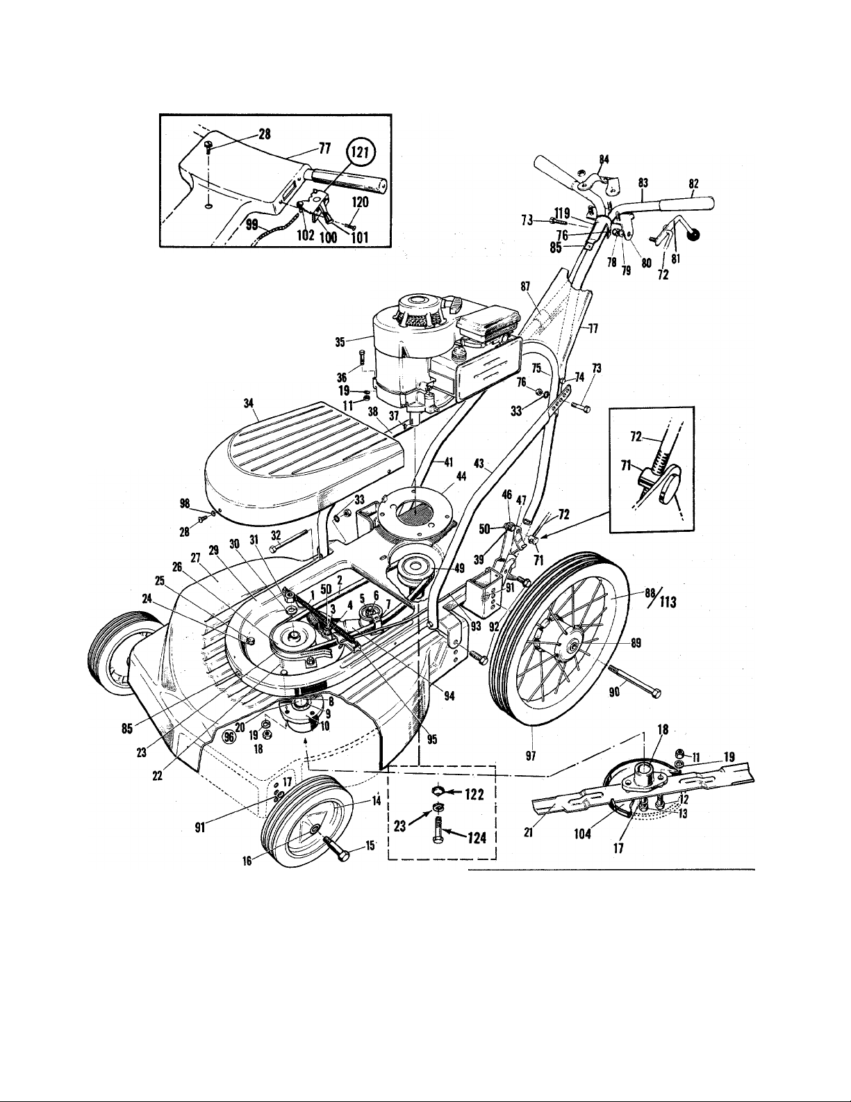
PARTS LIST FOR ROTARY MOWER MODEL NO. 110-530
Ref.
No.
Part
No.
1
732-158
2 754-109
736-300 Flat Washer - 3/8 I.D.
3
Blade Tension Spring
VBelt - 1/2x43 *
NAME OF PART
4 710-373 Shoulder - Special
5 756-370
Idler Bearing Assembly
6 712-372 Centerlock - Hex Nut — 5/16—18 thread *
310-7353 Bracket — Belt 77
7
711-212
8
9 741-120
719-120
10
712-123 Hex Nut - 5/16-24 thread *
11
12
710-117
Sleeve
Bearing - Upper
Spindle Housing
Hex Head Cap Screw (heat treated) —
5/16-24 X 1 long
710-113 Hex Hd.Cap Sew. 3/8-24 x 1-5/8 long *
13
501-9383
14
738-213 Axle Bolt - 5/8 length thread
15
741-114
16
17
736-169
18 748-100
19
736-119
711-240 Spindle
20
312-7581 Blade - 22’« 93
21
710-122
22
312 8324
23
712-123
24
710-122
25
26
27
28
29
3-9925
395-8756
710-473
395-8280 Frame Assembly
Wheel Ass’y - 8” Waffle - B.B. 85 712-526 Speed Nut - 10-24 thread *
Ball Bearing
Spring Lockwasher - 3/8 screw *
Blade Adapter
Spring Lockwasher — 5/16 screw *
Hex Hd. Cap Sew. 5/16—24 x 1 long *
Belt Guard
Hex Nut — 5/16—24 thread* 96
HexHd. Cap Sew. 5/16—24 x 1 long *
Pulley - 4”
Deck Assembly — 22” 99
Truss Hd. Mach. Sew. 10-24 x 1/2 long * 100
30 736-921 Spring Lockwasher - 1/2 screw * 102
712-922 Hex Jam Nut - 1/2-20 thread *
31
710-102 Hex Hd.Cap Sew. 1/4-20 x 2-1/2 long *
32
33 736-222 Ext. Lockwasher — 1/4 screw *
34 395-8295 Blade Spindle Cover
35
—
36 710-158
714-365
37
38 310-8328
39 736-108
310-8334
41
310-8327 Handle Support — Lower L.H.
43
310-8325
44
738-234
46
Engine
Hex Hd. Cap Sew. 5/16-24 x 1-1/4 long *
Key - Hi Pro #505 *
Handle Support - Lower R. H.
Flat Washer — 33/64 I.D. *
Handle - Lower H. W.
Belt Trap Assembly
Pivot Screw
47 310-9372 Pivot Bracket
756-110 Pulley - Engine
49
50
51
712-430
300-8809
Elastic Stop Nut — 3/8—16 thread *
Reinforcement Plate
Ref.
No.
Part
No.
NAME OF PART
71 711-179 Ferrule
72 711-180
Control Rod
73 710-606 Hex Hd.Cap Sew. 1/4—20 x 1-1/2 long *
74 710-106 Hex Hd.Cap Sew. 1/4-20 x 1-1/4 long *
75 712-287 Hex Nut — 1/2—20 thread *
76
712-107 Centerlock - Hex Nut — 1/4—20 thread *
395-9366
712-324
78
736-325
79
80 310-8376
310-8373
81
Control Panel
Elastic Stop Nut — 1/4—20 thread *
Flat Washer - .265 I.D. *
Lockout Bracket Assembly
Lockout Lever Assembly
82 305-7072 Grip — White
83 310-9364
84
310-8378 Clamp Bracket
746-145
87
734-180
88
741-113
89
90 738-114
736-105
91
710-209
92
310-9373
94
310-8298
310-9371
95
901-7805
97
734-179
98
736-147
732-139
310-8508
101
305-7470
901-7627
104
312-7919
no 710-938
Handle - Upper
Cable Clip
Wheel Assembly — 16” less tire
Ball Beating
Axle Bolt
Belleville Washer
SEMS Hex Hd. Cap Sew. 3/8-16 x 5/8 Ig.*
Control Rod
Idler Bracket Assembly
Brake Lever
Blade Spindle Ass’y —Complete H.W.
Tire - Rib Tread 16 x 1.75
Ext. Lockwasher - # 10 screw *
Conduit 8s Wire 37-1/2 x 39-13/16
Control Bracket Assembly — Throttle
Knob
Ferrule Assembly — Complete
Anti Scalp Plate — 8-1/2”
Allen Set Screw — 1/4-28 x 1/4 long*
(not shown)
741-107
111
Bearing—Lower-Blade Spindle
113 502-8761 Wheel Ass’y Complete
736-154 Washer
114
115 721-105
737-479
116
Seal
Zerk Fitting
117 728-649 Rivet
754-647 Brake Shoe
118
119 310-8378
120 710-148
121 310-8357
122 736-112
123 736-169
710-152
124
718-132
Clamp Bracket
Thread Cut Screw #8—32 x 3/8 Ig.*
Throttle Control - Complete
Belleville Washer
Lockwasher 3/8 Screw. *
Hex Head Cap Screw 3/8 — 24 x 1 Ig. *
Plastic Cap — Rear Wheel (not shown)
*For faster service obtain standard nuts, bolts, and washers locally. If these items cannot be obtained locally, order by part
number and size as shown on parts list.
FORM NO. 770-2393C
Page 4

ASSEMBLY INSTRUCTIONS
8. Fasten control panel to upper handle with cap screws and
locknuts at lower holes and truss head screw through upper
hole. Tighten all nuts and bolts.
5. Assemble speed nut to clamp bracket. Assembly clamp,
bracket to upper handles with long yellow bolt and nut as
shown.
2. Assemble upper handle parts with cap
screws and locknuts as shown —^
BLADE SPINDLE COVER
7. Assemble throttle control to
handle panel with two sheet
metal screws.
j 6. Assemble lockout bracket
assembly to upper handle.
/ A / Tighten nuts
securely.
4. Assemble upper handles and lower handle
supports to lower handle assembly with
cap screws and locknuts. Position sup
ports for most convenient height.
Use lower holes only.
3. Attach lower handle supports to frame assembly
with cap screws, lockwashers and hex nuts
9. Blade Engagement Assemblya. Remove Blade Spindle Cover by removing three screws.
b. Move brake lever to rear position so belt is slack.
c. Insert ferrule into blade bracket assembly from the left.
d. Screw rod into ferrule.
e. Assemble control handle to control rod as shown.
f. Adjust control rod. A slight pressure should be needed to operate lockout lever.
Too much pressure can break lever assembly or control rods. Readjust control
rods if pressure is too great.
g. Replace Blade Spindle Cover.
FORM N0.770 1847D
Page 5

OPERATION
1. Before starting engine, check LUBRICATION
INSTRUCTIONS.
2. Check lockout control handle for proper operation.
If too great a pressure is needed to operate these
controls, damage can be done to both the mechanism
and the rods. Readjust so only slight pressure is
needed to operate the blade engaging control. See
ASSEMBLY INSTRUCTIONS Step 9.
3. Service engine with gasoline and oil. See engine
instructions for complete care and maintenance of
engine. READ DIRECTIONS CAREFULLY.
4. Be sure engine crankcase is filled to capacity with
proper grade of oil.
5. Move control handle to “OFF” position.
6. Move throttle control lever to “Choke” position.
7. Crank engine. Move throttle control lever to “Fast”
position as soon as engine fires. Use choke as
needed to keep engine running during warm up period.
8. Put blade into motion by moving blade control handle
to “On” position.
3. Cutting height adjustment is made by removing and
moving axle bolts to the desired positions. Cutting
height will be raised as axle bolts are moved to
lower mounting holes and lowered as axle bolts are
moved to higher mounting holes. All axle bolts must
be mounted in the same relative position to the deck.
When wheels are mounted to the deck, the crown
shape washers must be assembled with the crown
away from the deck. This is necessary to prevent
the axle bolts from loosening.
4. If throttle adjustment becomes necessary, the throttle
control wire may be rèset as follows:
a. Loosen, but do not remove, screw securing throttle
control wire assembly at engine.
b. Move throttle control lever on handle to “Choke”
position.
c. Move lever to which control wire is fastened to
engine to full choke position. Retighten screw to
secure throttle control wire assembly.
LUBRICATION
Important: Always stop engine and disconnect spark
plug wire before cleaning, lubricating or doing any kind
of work on the lawn mower.
To engage the blade with the engine running . . .
a. Move the throttle control lever to “Fast” position.
b. Engage the blade engagement handle SLOWLY.
c. Adjust engine speed.
9. A brief break-in period is essential to insure maxi
mum engine and mower life. This consists of running
the engine a half speed for a period of time required
to use one tank of gasoline. It is also recommended
to change crankcase oil after the first five hours of
operation or as operating conditions dictate. Always
check oil before operating the mower. BE SURE
CRANKCASE IS FULL.
10. Proper lubrication must be maintained at all times.
11. Appropriate clothing should be worn when cutting
brush or heavy weeds. Safety shoes and safety
glasses are highly recommended.
12. The engine is stopped by moving the throttle control
lever to “STOP” position.
ADJUSTMENT
1. Wheel bearings are ball bearings. Use SAE 30
engine oil.
2. Throttle — Periodically lubricate throttle control
lever and entire length of throttle wire assembly
with a few drops of SAE 30 engine oil for ease of
operation.
3. Engine — Follow engine manual for lubrication
instructions. Check oil level before each mowing.
4. Friction point between idler bracket assembly (Ref.
No.94) and deck should be greased once each season
with a multi-purpose grease.
5. ' Blade Spindle Assembly — The Blade Spindle
Assembly is equipped with a grease fitting. Use
grass discharge chute for access to the fitting
located under the deck. Use multi-purpose grease.
Lubricate PRIOR to initial use and every 25 hours
thereafter. CAUTION: Be sure spark plug wire is
disconnected and grounded.
1. Handles may be adjusted by changing the position
of the lower support mounting holes. When this
change is made, it may also be necessary to check
the adjustment of the control rod. See Step 9 in
ASSEMBLY INSTRUCTIONS.
2. Control rod adjustment is made as shown in ASSEM
BLY INSTRUCTIONS Step 9.
MAINTENANCE
Important: Always stop engine and disconnect spark
plug wire before cleaning, lubricating or doing any kind
of work on the lawn mower.
1. Cutting Blade — Remove all nuts and bolts holding
the blade to the blade hub.
FORM N0.770-1847E
Page 6

When sharpening blade, follow the original angle of
of grind as a guide. It is extremely important that
each cutting edge receives an equal amount of grind
ing to prevent an unbalanced blade. An unbalanced
blade will cause excessive vibration when rotating
at high speeds and may cause damage to the mower.
Upon reassembling, make certain all parts
are
assembled properly and tightened securely.
2. Deck — The underside of mower deck should be
cleaned after each period of use as grass clippings,
leaves, dirt and other matter accumulates. This
accumulation of grass clippings, etc. is undesirable
as it will invite rust and corrosion and may cause
an uneven discharge of grass clippings at next
cutting.
The deck may be cleaned by tilting the mower back
ward or on its right side and scraping clean with a
suitable tool or by washing with a stream of water
from a garden hose. CAUTION; Do not direct the
stream of water at a hot engine as damage to the
engine may result.
3. Belt replacement may be made as follows:
a. Remove blade spindle cover.
b. Remove front belt guard.
c. Remove blade tension spring.
d. Loosen belt on bracket of idler bearing assembly.
e. Remove brake lever assembly.
f. Remove damaged or worn belt.
g. Place new belt on engine pulley. Do not bend
belt guard pins. Belt should be inside of pins.
h. Work belt to front and mount on blade spindle
pulley. Replace front belt guard.
i. Replace brake lever assembly.
j. Slip belt on idler pulley between pulley and belt
bracket.
k. Replace blade tension spring.
l. Move blade lockout handle to “ON” position.
m. Position belt bracket on idler pulley to clear the
tightened belt. Secure belt bracket in position.
See Drawing page “C”.
n. Replace blade spindle cover.
4. Storage — The following steps should be taken to
prepare lawn mower for storage:
a. Clean and lubricate mower thoroughly as describ
ed in the preceding instructions.
b. Refer to engine manual for correct engine storage
instructions.
c. Coat mower's cutting blade with multi-purpose
grease to prevent rusting.
d. Place blocks under deck to raise tires clear of
floor.
e. Store mower in a dry, clean area.
USING YOUR ROTARY MOWER
For best results do not cut wet grass because it tends
to stick to the underside of the mower, thus preventing
proper discharge of grass clippings. If wet grass must
be cut, reduce engine speed to help distribute the
clippings more effectively.
New grass should be treated as wet grass, otherwise a
normal walking speed is about the right pace for
efficient mowing.
The best mowing pattern is one that allows the clippings
to discharge towards the uncut part of thé lawn. This
permits recutting of the clippings to further pulverize
them. When cutting high weeds, discharge towards cut
portion then recut at right angle to first direction.
Lawns should be cut in fall as long as there is growth.
BLADE IDLER BRACKET ASSEMBLY DETAIL
BRAKE SHOE 754-647 (118)
BELT WEAR
Belt clips improperly positioned
will cause premature belt wear.
The belt clip must completely
clear the belt when the belt is
tightened. It should also assist in freeing the
belt from the blade spindle pulley when the belt
is loose. This may be checked by removing the
blade spindle cover.
FORM NO. 770-1847F
RIVET 728-649 (117)
IDLER BRACKET ASSEMBLY (94)
IDLER BEARING (5)
756-370
HEX LOCK NUT (6)
712-372
BELT CLIP (7)
310-7353
Page 7

'ì
NOTE: PARTS SHOWN
IN DOTTED LINES
NOT INCLUDED
IN ASSEMBLY.
736-154 114
BEARING 11/16
741-120
BEARING 3/4
741-107 111
SEAL
721-105 115
41
^ ' 714-365 37
REINFORCEMENT PLATE
300-8809 51
ZERK FITTING
737-479 116
SPINDLE HOUSING
719-120 10
CAUTION: 1. Bearing races must be firmly seated in Spindle Housing.
'2. Zerk Fitting should face Discharge Chute of Deck.
3. Lubricate every 8 to 10 hours with Shell General Purpose
Grease or Equivalent.
KEY
SPINDLE
711-240 20
KEY
'714-365 37
BLADE SPINDLE
ASSEMBLY
901-7805
736-119 19
HEX NUT
712-123 11
SPINDLE ASSEMBLY
DECjK 27
736-119 19
HEX NUT
712-123 11
ZERK FITTING
737-479 116
Z
o
Page 8

FORM NO. 770-1847H
PRINTED IN U.S.A.
 Loading...