

Page 1

OWNEirS GUIDE
ASSEMBLY • OPERATION • MAINTENANCE • PARTS
$1.00
Oi "
^ * Model Numbers
ROTARY 110-516R000
MOWERS 110-518R000
QTi C/mtE«.- [MMDj
on 0/mfER.-(2orr)
Important: Read Safety Rules and Instructions Carefully
PRINTED IN U.S.A.
FORM NO. 770-7046E
Page 2

INDEX
Slope Gauge.....................................................................3
Contents of Hardware Pack
Rules for Safe Operation.................................................5
Assembly
Controls
Operation........................................................................11
Adjustments....................................................................12
Lubrication
Maintenance
Off-Season Storage........................................................14
Trouble Shooting Guide
Illustrated Parts..............................................................16
Repair Parts List......................................................17, 18
Parts Information
A
..........................................................................
..........................................................................
.....................................................................
...................................................................
...........................................
The use of any accessory on this Rotary Mower other than those manufactured by the mower manufacturer
is not recommended.
WARNING: DO NOT operate the nower without the entire grass catcher or chute defiector in piace. DO NOT operate the mower without the protective shield on the rear of the deck in place.
NOTE: Under normal usage bag material is subject to wear and should be checked periodically. Be sure
any replacement bag complies with the m 3wer manufacturer’s recommendations. For replacement bags,
use only factory authorized replacement t ag.
............................................
................................................
Bad: Cover
4
6
10
13
13
15
Dear Customer,
So often throughout the year we are all in a
rush to meet our daily obligations.
However, we at MTD Products Inc are tak
ing a quick moment out to say.. .
“Thank you for your business.’’
Sincerely,
MTD PRODUCTS INC
INSTRUCTIONS GIVEN WITH THIS SYM
BOL ARE FOR PERSONAL SAFETY. BE
A
SURE TO FOLLOW THEM.
WARNING: This unit is equipped with an internal combustion engine and should not be used on or near any unim
proved forest-covered, brush-covered or grass-covered land unless the engine’s exhaust system is equipped with
a spark arrester meeting applicable local or . itate laws (if any). If a spark arrester is used, it should be maintained
in effective working order by the operator.
In the State of California the above is required by law (Section 4442 of the California Public Resources Code).
Other states may have similar laws. Federal I iws apply on federal lands. A spark arrester for the muffler is available
through your nearest engine authorized se vice dealer.
Page 3
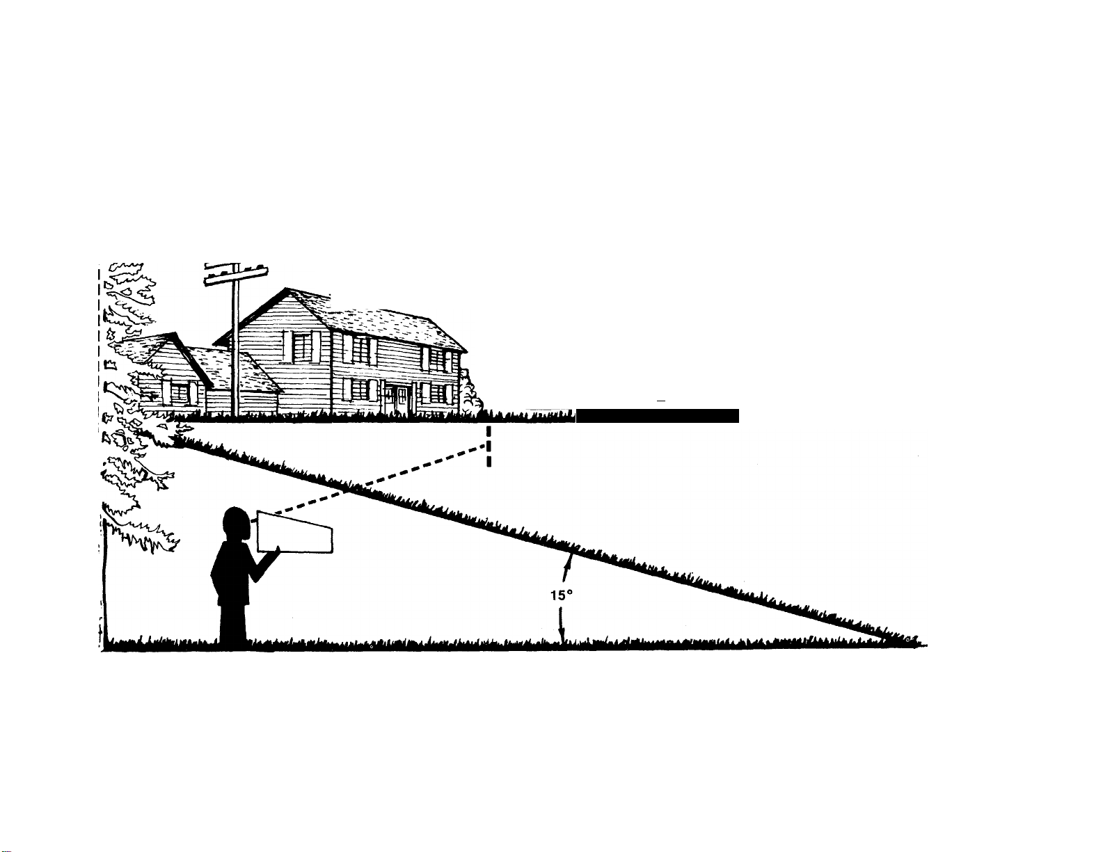
--UUIMK ^nisLine-
USE THIS SHEET AS A GUIDE TO DETERMINE SLOPES WHERE YOU MAY NOT OPERATE SAFELY.
SIGHT AND HOLD THIS LEVEL WITH A VERTICAL TREE
A-
-----------------
^------------------
....
....................
CO
.
.
................
......
A POWER POLE
----------------
A CORNER OF A BUILDING
I
I —
!
................................................
........
OR A FENCE POST
n--------------f
..
.........
ii
..............................
......
o
0
n
(0
(/>
3-
o
o
0)
(A
0)
(D
■D
0>
O
O
C
•NN
c
(D
C/>
m
O
O
AC WARNING I
Do not mow on inclines with a slope in excess of IS degrees (a rise of approximately 2V2 feet every 10 feet). A
riding mower couid overturn and cause serious injury. If operating a waik-behind mower on such a slope, it is
extremely difficult to maintain your footing and you could slip, resulting in serious injury.
Operate RIDING mowers up and down slopes, never across the face of slopes.
Operate WALK-BEHIND mowers across the face of slopes, never up and down slopes.
(D
(D
—t
O
3
o
o
Page 4
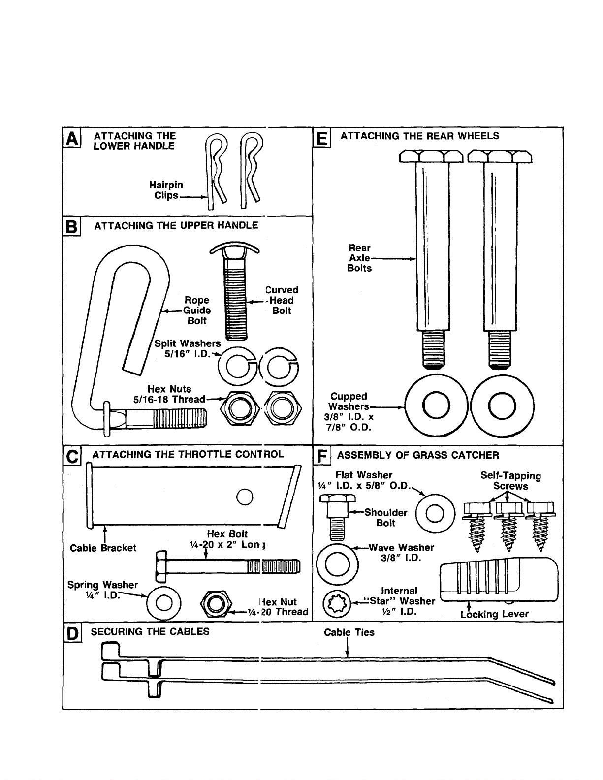
CONTENTS OF HARDWARE PACK
Remove this sheet from your owner’s manual and lay the hardware on the illustration for identification purposes.
After assembly, keep the Slope Gauge whicf is on the reverse side of this sheet for future use.
(Hardware pack may contain extra items which are not used on your unit.)
o
c
>
3-
M
<D
I I I I I I
0
INCHES
Itili
1
I
I I I
I
I I I
I
I
I
Page 5

A
IMPORTANT
RULES FOR SAFE OPERATION
THIS SYMBOL POINTS OUT IMPORTANT SAFETY INSTRUCTIONS WHICH, IF NOT FOLLOWED, COULD ENDANGER THE PERSONAL SAFETY
AND/OR PROPERTY OF YOURSELF AND OTHERS. READ AND FOLLOW ALL INSTRUCTIONS IN THIS MANUAL BEFORE AHEMPTING
TO OPERATE YOUR LAWN MOWER. FAILURE TO COMPLY WITH THESE INSTRUCTIONS MAY RESULT IN PERSONAL INJURY. WHEN
YOU SEE THIS SYMBOL- ^ HEED ITS WARNING.
DANGER
Ai
Your lawn mower was built to be operated according to the rules for safe operation in this manual. As
with any type of power equipment, carelessness or error on the part of the operator can result in serious
injury. If you violate any of these rules, you may cause serious injury to yourself or others.
A
A
TRAINING
Read this owner’s guide carefully in its entirety before attempting
to assemble or operate this machine. Be completely familiar with
the controls and the proper use of this machine before operating
it. Keep this manual in a safe place for future and regular reference
and for ordering replacement parts.
2. Your rotary mower Is a precision piece of power equipment, not
a plaything. Therefore, exercise extreme caution at all times.
3. Never allow children to operate a power mower. Only persons well
acquainted with these rules of safe operation should be allowed
to use your mower.
4. Keep the area of operation clear of all persons, particularly small
children and pets. Stop engine when they are in the vicinity of
your mower to help prevent blade contact or thrown object in
jury. Although the area of operation should be completely cleared
of foreign objects, an object may have been overlooked and could
be accidently thrown by the mower in any direction and cause
serious personal injury to the operator or any others allowed in
the area.
PREPARATION
1. Thoroughly inspect the area where the equipment is to be used.
Remove all stones, sticks, wire, bones and other foreign objects
which could be picked up and thrown by the mower in any direc
tion and cause serious personal injury to the operator or any others
allowed in the area.
2. Always wear safety glasses or eye shields during operation or while
performing an adjustment or repair, to protect eyes from foreign
objects that may be thrown from the machine in any direction.
3. Wear sturdy, rough-soled work shoes and close-fitting slacks and
shirts to avoid entanglement in the moving parts. Never operate
a unit in bare feet, sandais, or sneakers.
4. Check the fuel before starting the engine. Gasoline is an extreme
ly flammable fuel. Do not fill the gasoline tank indoors, while the
engine is running, or until engine has been allowed to cool for
two minutes after running. Replace gasoline cap securely and wipe
off any spilled gasoline before starting the engine as it may cause
a fire or explosion.
5. Disengage the self-propelled mechanism or drive clutch on units
so equipped before starting the engine.
6. The blade control handle is a safety device. Never attempt to bypass
its operation. Doing so makes the safety device inoperative and
may result in personal injury through contact with the rotating
blade. The blade control handle must operate easily in both
directions.
7. Never attempt to make a wheel or cutting height adjustment while
the engine is running.
8. Never operate the equipment in wet grass. Always be sure of your
footing. A slip and fall can cause serious personal injury. Keep
a firm hold on the handle and walk, never run. Mow only in daylight
or in good artificial light.
9. For your safety, use the slope gauge included as part of this manual
to measure slopes before operating this unit on a sloped or hilly
area. If the slope is greater than 15“ as shown on the slope gauge,
do not operate this unit on that area or serious injury could result.
OPERATION
1.
Do not change the engine governor settings or overspeed the
engine. Excessive engine speeds are dangerous.
2.
Do not put hands or feet near or under rotating parts. Keep clear
of the discharge opening at all times as the rotating blade can
cause injury.
Stop the blade when crossing gravel drives, walks or roads.
After striking a foreign object, stop the engine, remove the wire
from the spark plug, and thoroughly inspect the mower for any
damage. Repair the damage before restarting and operating the
mower.
If the equipment should start to vibrate abnormally, stop the engine
and check immediately for the cause. Vibration is generally a warn
ing of trouble.
Shut the engine off and wait until the blade comes to a complete
stop before removing the grass catcher or unclogging the chute.
The cutting blade continues to rotate for a few seconds after the
engine is shut off. Never place any part of the body in the blade
area until you are sure the blade has stopped rotating.
7.
Before cleaning, repairing or inspecting, make certain the blade
and all moving parts have stopped. Disconnect the spark plug wire,
and keep the wire away from the spark plug to prevent accidental
starting.
Do not run the engine indoors.
Mow across the face of slopes, never up-and-down. Exercise ex
treme caution when changing direction on slopes. Do not mow
excessively steep slopes. Always be sure of your footing. A slip
and fall can cause serious personal injury.
10.
Never operate mower without proper guards, plates or other safety
protective devices in place.
11.
Do not operate this mower with the chute door open, unless the
complete grass catcher or chute deflector is properly mounted
on the mower.
MAINTENANCE AND STORAGE
1. Check the blade and engine mounting bolts at frequent intervals
for proper tightness.
2. Keep all nuts, bolts, and screws tight to be sure the equipment
is in safe working condition.
3. Never store the equipment with gasoline in the tank inside of a
building where fumes may reach an open flame or spark. Allow
the engine to cool before storing in any enclosure.
4. To reduce fire hazard, keep the engine free of grass, leaves, or
excessive grease.
5. Check the grass catcher bag frequently for wear or deterioration.
For safety protection, replace only with new bag meeting original
equipment specifications.
Page 6
ASSEMBLY INSTRUCTIONS
IMPORTANT: This unit is shipped WITHOUT
GASOLINE or OIL. After assembly, service engine
with gasoline and oil as instructed in the separate
engine manual packed with your unit.
NOTE: Reference to right or left hand side jf the
mower is observed from the operating posi ion.
Tools Required for Assembly
(1) Pair of Pliers
(1) 1/2" Wrench*
(2) 7/16" Wrenches*
(1) Adjustable Wrench
*Or two 6" Adjustable Wrenches
UNPACKING
1. Remove the lawn mower from the carton by open
ing the top flaps and lifting the unit out. Be careful
of the staples. Make certain all parts and literature
have been removed from the carton before the car
ton is discarded.
2. Disconnect and ground the spark plug wire against
the engine. Check beneath the deck for any card
board packaging. Remove if present.
3. Stretch out all control cables and place on the floor.
Be careful not to bend or kink the cables at any
time during assembly.
4. Remove page four from this manual and lay the
contents of the hardware pack on the illustration
for identification.
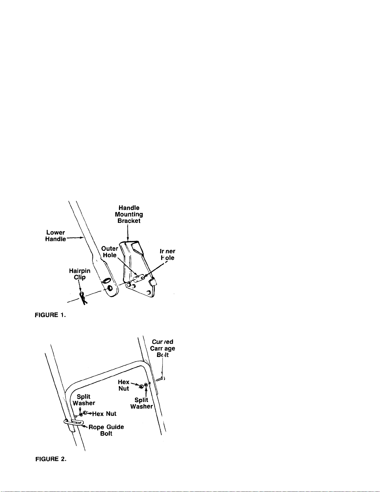
ATTACHING THE LOWER HANDLE (Hardware A)
1. Attach the lower handle by placing the bottom
holes in the lower handle over the weld pins on the
handle mounting brackets on the rear of the deck.
2. Using a pair of pliers, squeeze one leg of the lower
handle against the handle mounting bracket. In
sert the hairpin clip into the inner hole on the weld
-------
pin. See figure 1. Repeat on other side.
NOTE: There are two (2) holes in the handle mounting
brackets. Place the hairpin clip in the inner hole for
operation. Outer hole is for storage.
ATTACHING THE UPPER HANDLE (Hardware B)
1. Place the upper handle in position over the lower
handle. The blade control handle (attached to the
upper handle) must be facing up.
NOTE: The right hand side of the handle will be secured
with the rope guide boit. However, left handed operators
may assemble the rope guide bolt to the left side of the
handle for easier starting by foliowing steps 2 and 3 and
reversing the ieft and right hand instructions.
2. Secure the left hand side of upper handle using
the curved head bolt, split washer and hex nut as
-------
shown in figure 2.
Insert the rope guide bolt through the right hand
3.
side of upper and lower handle from the outside
in. Secure with split washer and hex nut, finger
tight only at this time.
Page 7

AHACHING THE THROHLE CONTROL (Hardware C)
The throttle control is attached to the engine. Attach
the throttle control to the left side of upper handle as
-follows. See figure 3.
1. Route the throttle control cable inside the handle
mounting bracket and beneath the lower handle.
2. Place cable bracket against left side of upper han
dle, lining up the hole in the bracket with the bot
tom hole in upper handle. Place 1/4" hex bolt
through cable bracket and handle, from the inside
to the outside.
3. Place throttle control on the hex bolt (outside of
the upper handle), with the throttle lever facing up
ward. Secure with spring washer (cupped side
against the throttle control) and hex nut.
ATTACHING THE BRAKE CABLE
1. The brake cable is attached to the engine, and has
a “Z” fitting on the loose end. Route the brake
cable below the lower handle. Place end of cable
through the hole in the bracket as shown in figure
-------
4. Be careful not to bend or kink the cable at any
time. Push the plastic fitting until it locks into the
hole in the bracket.
WARNING: Brake cable must be assem
bled as shown for proper blade brake
A
2. Hook the “Z” end of the brake cable into the hole
operation.
in the blade control handle from the inside to the
outside as shown in figure 4.
SECURING THE CABLES (Hardware D)
Secure both cables to the left side of the handle as
follows.
1. Insert posts on cable ties into holes provided on
the lower handle. The holes may be either on the
-------
inside or outside of the handles. See figure 5A.
2. Secure the cables with the cable ties. See figure
5B.
3. Trim excess ends of cable ties.
ATTACHING THE STARTER ROPE
1. The starter rope is inside the top of the engine. Ad
ditional rope may be wound around the starter han
dle. If so, unwind the rope from the handle.
2.
With the spark plug wire disconnected and
grounded, depress the blade control handle and
pull the rope out of the engine.
3.
Slip the starter rope into the rope guide bolt as
—shown in figure 6.
4. Tighten the hex nut on the rope guide bolt
securely.
Page 8

ATTACHING THE REAR WHEELS (Hardware E)
-Assemble the rear wheels as follows. See figure 7.
1. Move the wheel height adjusters so the deck is in
the lowest cutting position.
2. Lift the rear of the unit up and block securely.
3. Insert axle bolt through one rear wheel. Place
cupped washer on axle bolt (crowned side of
washer goes against the wheel).
4. Thread axle bolt into rear hole of pivot bar. Tighten
securely.
5. Assemble other rear wheel in the same manner.
INSTALLATION OF HUB CAPS (Optional)
1. If your mower is equipped with front hub caps
which have four tabs, line up the tabs on the hub
caps with the holes in the wheels. Push to lock in
position.
2. If your mower is equipped with 2" wide tires, place
front hub caps in position against the inner hub of
the wheel. Press firmly around the center portion
of hub cap in a circular motion, similar to install
ing a lid on a round, plastic container. See figure
-------
8. The hub caps are flexible and will snap over the
3V2" diameter wheel hubs.
FIGURE 8.—Optional Hub Caps
FINAL ASSEMBLY OF MOWER
Make certain all nuts and bolts are tightened securely.
ASSEMBLY OF GRASS CATCHER (Hardware F)
NOTE; Make certain the grass bag is turned right side
out before assembling (warning label will be on the
outside).
There are three holes in the rear frame. With the
1.
holes on the upper side as shown in figure 9A, in
sert one end of the rear frame into the cloth chan
nel on the edge of the grass catcher bag. Feed all
the material on one side of the frame, then work
■it around the frame. See figure 9B.
FIGURE 9.
Page 9

2. Slide the ends of the front frame assembly into the
—ends of the rear frame as shown in figure 10A.
3. Secure front of bag to front frame by slipping
plastic channels on sides and bottom of bag over
frame. See figure 10B.
4. Attach the hardtop cover to the grass catcher as
—follows. See figure 11.
a. Place the cover in position on top of the grass
catcher. Press the rear frame into the channel
on the rear of the cover (beneath the rear
handle).
b. Slide the notches on the sides of the cover over
the front catcher frame.
c. Attach rear of cover to frame using the flat
washer and one self-tapping screw as shown
in figure 11. Attach the sides of the cover to
frame with the other two self-tapping screws.
Assemble the locking lever as follows:
a. Place wave washer on shoulder bolt (crowned
side of washer goes against the head of bolt).
b. Insert shoulder bolt up through hole in hardtop
-----
cover as shown in figure 12. Place “star”
washer over shoulder bolt.
c. Thread shoulder bolt into the grass catcher
locking lever, using a 9/16" socket wrench. Do
not overtighten. Locking lever must be able to
pivot.
Page 10

FIGURE 13.
Rear
Deflector
AHACHING BAG TO MOWER
Lift the rear deflector on the mower. Place the hooks
on the grass catcher over the pins on the back of the
mower. See figure 13. Release the rear deflector. Turn
the locking lever to the locked position to secure the
-rear deflector. See figure 13, inset.
To remove the grass catcher, turn the locking lever to
the unlocked position and lift the rear deflector on the
mower. Lift the grass catcher up, over the pins on the
back of the mower. Release the deflector.
BLADE CONTROL HANDLE
WARNING
THIS CONTROL MECHANISM IS /
SAFETY DEVICE NEVER ATTEMP
TO BYPASS ITS operation;
Throttle
Control
C:ONTROLS
The blade control handle is located on the upper han
dle of the mower. See figure 14. The blade control han
dle must be depressed in order to operate the unit.
Release the blade control handle to stop the engine and
blade.
A
THROTTLE CONTROL
The throttle control is located on the side of the upper
handle. It is used to regulate the engine speed.
A
RECOIL STARTER
The recoil starter handle is attached to the handle. See
figure 14. Stand behind the unit in the operating posi
tion to start the unit.
WARNING: The blade will be rotating whenever the engine is running.
WARNING: The throttle control cannot be used to stop the engine.
10
Page 11

OPERATION
TO REDUCE THE RISK OF INJURY. DO NOT
OPERATE MOWER UNLESS REAR TRAILING
SHIELD AND THIS GUARD OR ENTIRE
GRASS CATCHER IS IN ITS PROPER PLACE.
FIGURE 15.
Keep hands and feet away from the chute area on cut
ting deck. See figure 15.
The operation of any lawn mower can result in
foreign objects being thrown into the eyes, which
can resuit in severe eye damage.
Aiways wear safety glasses or eye
shields. We recommend wide vision
safety mask for over spectacles or
standard safety glasses.
NOTE: For shipping purposes your mower is set with
the wheels in a low cutting height position. For best
resuits raise the cutting position untii it is determined
which height is best for your lawn. See cutting height
adjustment section.
Metal Loop
on Spark
Piug Wire
Rubber Boot
FIGURE 16.
2. Open fuel shut-off valve. See figure 17.
3. Move throttle control lever all the way forward.
4. Standing behind the unit, depress the blade con
trol handle and hold it against the upper handle
as shown. See figure 18.
5. Grasp the recoil starter handle and pull back rapid
ly, extending rope fully. Return it slowly to the rope
guide bolt.
6. After engine starts, move throttle control to desired
engine speed.
NOTE: If any problems are encountered, refer to the
Trouble Shooting Guide on page 15.
GAS AND OIL FILL-UP
Service the engine with gasoline and oil as instructed
in the separate engine manual packed with your
mower. Read instructions carefully.
WARNING: Never fill fuel tank indoors,
with engine running or until the engine has
▲
been allowed to cool for at least two
minutes after running.
TO START ENGINE AND ENGAGE BLADE
1. Attach spark plug wire to spark plug. If unit is
equipped with a rubber boot over the end of the
spark plug wire, make certain the metal loop on
the end of the spark plug wire (inside the rubber
boot) is fastened securely over the metal tip on the
spark plug. See figure 16.
FIGURE 18.
TO STOP ENGINE AND BLADE
1. Release the blade control handle to stop the
engine and blade.
11
Page 12

WARNING: The blade continues to rotate
for a few seconds after the engine is shut
A
2. Disconnect the spark plug wire and ground it
USING YOUR ROTARY MOWER
A
Be sure that lawn is clear of stones, sticks, wire, o other
objects which could damage lawn mower or e igine.
Such objects could be accidently thrown by the r lower
in any direction and cause serious personal injury to
the operator and others.
For the best results, do not cut wet grass becc use it
tends to stick to the underside of the mower, pr aventing proper discharge of grass clippings, and could
cause you to slip and fall. New grass, thick grass or
wet grass may require a narrower cut. Blade speed
should be adjusted to the condition of the lawi.
For best results, cut off one-third or less of th a total
length of the grass. Lawn should be cut in the fall as
long as there is growth.
This mower is designed to be operated at full t irottle
to give you the best cut and do the most effect! t/e job
of bagging the cut grass.
off.
against the engine to prevent accidental starting
while equipment is unattended.
WARNING: Never operate your unit
without either the rear deflector or (>ntire
grass catcher assembly in place.
FIGURE 19.
THROTTLE CONTROL ADJUSTMENT
If the carburetor choke does not close fully or if the
throttle control has been replaced, adjust the throttle
control as follows.
1.
Remove the screw shown in figure 20. Remove the
cable clamp from the cable.
2.
Push the throttle control lever on the handle all the
way forward to CHOKE position. Make certain the
throttle control lever remains in this position.
Push the control lever on the engine as far toward
the rear of the engine as it will go. Secure the cable
in this position with the cable clamp and screw.
Cable
Clamp
WARNING: If you strike a foreign object,
A
stop the engine. Remove wire from spark
plug, thoroughly inspect the mower f }r any
damage, and repair the damage before
restarting and operating the mower. I Exten
sive vibration of the mower during < iperation is an indication of damage. The unit
should be promptly inspected and
repaired.
ADJUSTMENTS
WARNING: Do not at any time make any
adjustment to lawn mower withoit first
A
CUTTING HEIGHT ADJUSTMENT
An adjusting plate and thumb lever at each whe ?l posi
tion provides cutting height adjustment. Each ac justing
plate has nine height positions. Height of cut will be
changed when the thumb lever is moved from one hole
to another. Simply depress the lever towards whnel and
move wheel and lever assembly to desired posil ion. All
wheels must be placed in the same relative position.
See figure 19.
stopping engine and disconnecting spark
plug wire.
FIGURE 20.
CARBURETOR ADJUSTMENTS
WARNING: If any adjustments are made to
the engine while the engine is running (e.g.
A
Minor carburetor adjustments may be required to
compensate for differences in fuei, temperature,
altitude and ioad. To adjust carburetor, refer to the
separate engine manual packed with your mower.
NOTE: A dirty air cleaner will cause an engine to run
rough. Be certain air cleaner is clean and attached to
the carburetor before adjusting carburetor. Refer to the
separate engine manual.
carburetor), keep ciear of aii moving parts.
Be carefui of heated surfaces and muffler.
12
Page 13

LUBRICATION
WARNING: Always stop engine and
disconnect spark plug wire before clean
A
Blade Control—Lubricate the pivot points on the blade
control handle and the brake cable at least once a
season with light oil. See figure 21. The blade control
must operate freely in both directions.
FIGURE 21.
Discharge Chute Deflector—The torsion spring and
pivot point should be lubricated periodically with light
oil to prevent any rust or binding. Deflector must work
freely.
Wheels—Mower may be provided with ball bearing
wheels. Lubricate at least once a season with light oil.
Also, if the wheels are removed for any reason,
lubricate the surface of the axle bolt and the inner sur
face of the wheel with light oil. A 4 oz. plastic bottle
of light oil lubricant is available. Order part number
737-0170. Engine oil may also be used.
Engine—Follow engine manual for lubrication in
structions.
Throttle—Periodically lubricate throttle control lever
and throttle wire assembly with a few drops of light oil
for ease of operation.
ing, lubricating or doing any kind of work
on lawn mower.
MAINTENANCE
CUTTING BLADE
When removing the cutting blade for sharpening or
replacement, protect hands by using heavy gloves or
a rag to grasp the cutting blade. Remove the bolt and
bell washer which hold the blade and adapter to the
engine crankshaft. Remove the blade and adapter from
the crankshaft.
If the blade or blade adapter needs replacing, remove
the two small bolts, lock washers and nuts which hold
the blade to the adapter.
WARNING: Periodically inspect the blade
adapter for cracks, especially if you strike
A
When sharpening the blade, follow the original angle
of grind as a guide. It is extremely important that each
cutting edge receives an equal amount of grinding to
prevent an unbalanced blade. An unbalanced blade will
cause excessive vibration when rotating at high speeds,
may cause damage to the mower and could break,
causing personal injury.
It is recommended that the blade always be removed
from the adapter for the best test of balance.
The blade can be tested by balancing it on a round shaft
screwdriver. Remove metal from the heavy side until
it balances evenly.
Before reassembling the blade and the blade adapter
to the unit, lubricate the engine crankshaft and the inner
surface of the blade adapter with light oil. Lubricating
the bolt holes, bolts and inner surface of the nuts with
light oil is also recommended. A 4 oz. plastic bottle of
light oil lubricant is available. Order part number
737-0170. Engine oil may also be used.
When replacing the blade, be sure to install the blade
with the side of the blade marked “Bottom” (or with
part number) facing the ground when the mower is in
the operating position.
Blade Mounting Torque
Center Bolt and Blade Adapter Bolts:
375 in. lb. min., 450 in. lb. max.
To insure safe operation of your unit, all nuts and bolts
must be checked periodically for correct tightness.
a foreign object. Replace when necessary.
WARNING: Be sure to disconnect and
ground the spark plug wire before perform
A
NOTE: When tipping the unit, empty the fuel tank and
keep engine spark plug side up.
TROUBLE SHOOTING
Refer to page 15 of this manual for trouble shooting
information.
ing any repairs or maintenance.
DECK
The underside of the mower deck should be cleaned
after each use to prevent a buildup of grass clippings,
leaves, dirt or other matter. If this debris is allowed to
accumulate, it will invite rust and corrosion, and may
cause an uneven discharge of grass clippings at the
next cutting.
The deck may be cleaned by tilting the mower and
scraping clean with a suitable tool (make certain the
spark plug wire is disconnected).
13
Page 14

ENGINE
Refer to the separate engine manual for engine
maintenance instructions.
Maintain engine oil as instructed in the seaarate
engine manual packed with your unit. Read and follow
instructions carefully.
Service air cleaner every 25 hours under norm il con
ditions. Clean every few hours under extremely dusty
conditions. Poor engine performance and flooding
usually indicates that the air cleaner should k e ser
viced. To service the air cleaner, refer to the separate
engine manual packed with your unit.
The spark plug should be cleaned and the ga|) reset
once a season. Spark plug replacement is lecom-
mended at the start of each mowing season; check
engine manual for correct plug type and gap
specifications.
Clean the engine regularly with a cloth or brush. Keep
the cooling system (blower housing area) clean to per
mit proper air circulation which is essential to engine
performance and life. Be certain to remove aii grass,
dirt and combustible debris from muffler area
OFF-SEASON STORACiE
The following steps should be taken to prepaie lawn
mower for storage.
1. Clean and lubricate mower thoroughly as de
scribed in the lubrication instructions.
2. Refer to engine manual for correct engine storage
instructions.
3. Coat mower’s cutting blade with chassis grease
to prevent rusting.
4. Store mower in a dry, clean area.
NOTE: When storing any type of power equipment in
an unventiiated or metai storage shed, care shouid be
taken to rust-proof the equipment. Using a light oil or
silicone, coat the equipment, especially cables and all
moving parts.
HANDLE STORAGE
The handle may be placed in an upright position for
storage. Move hairpin clips to outer hole on weld pins.
See figure 1. Press outward on the bottom of the lower
handle and push forward. The handle will lock in this
position.
To place the handle in the operating position, remove
the starter rope from the rope guide bolt. Grasp the
lower handle at the bottom, press outward slightly and
tip the handle backward. Place the hairpin clips in the
inner holes. With the spark plug wire disconnected and
grounded, depress the blade control handle and pull
the starter rope out from the engine. Slip the starter
rope into the rope guide bolt.
14
Page 15

TROUBLE SHOOTING GUIDE
Trouble
Engine fails to start 1. Blade control handle disengaged.
Engine runs erratic
Engine overheats
2. Spark plug wire disconnected.
3. Throttle control lever not in CHOKE
or START position.
4. Fuei shut-off valve closed.
5. Fuel tank empty, or stale fuel.
6. Blocked fuel line.
7. Faulty spark plug.
8. Engine flooded.
1. Unit running in CHOKE or START
position.
2. Spark plug wire loose.
3. Blocked fuel line or stale fuel.
4. Vent in gas cap plugged.
5. Water or dirt in fuel system.
6. Dirty air cleaner.
7. Carburetor out of adjustment.
1. Engine oil level low.
2. Air flow restricted.
3. Carburetor not adjusted properly.
Possible Cause(s) Corrective Action
1. Engage blade control handle.
2. Connect wire to spark plug.
3. Move throttle lever to CHOKE or
START position.
4. Open fuel shut-off valve.
5. Fill tank with clean, fresh gasoline.
6. Clean fuel line.
7. Clean, adjust gap or replace.
8. Remove spark plug, dry the plug, and
crank engine with plug removed and
throttle in off position. Replace spark
plug, connect wire and resume starting
procedures.
1. Move throttle lever to FAST
position.
2. Connect and tighten spark plug wire.
3. Clean fuel line; fill tank with clean,
fresh gasoline.
4. Clear vent.
5. Drain fuel tank. Refill with fresh fuel.
6. Clean air cleaner.t
7. Adjust carburetor.f
1. Fill crankcase with proper oil.
2. Remove blower housing and clean.t
3. Adjust carburetor.f
Occasional skip
(hesitates) at high speed
Idles poorly
Excessive vibration 1. Cutting blade loose or unbalanced.
Mower will not
discharge grass
Uneven cut
tRefer to separate engine manual packed with your unit.
1. Spark plug gap too close.
2. Carburetor idle mixture adjustment
improperly set.
1. Spark plug fouled, faulty or gap too wide.
2. Carburetor improperly adjusted.
3. Dirty air cleaner.
2. Bent cutting blade.
1. Engine speed too low.
2. Wet grass.
3. Excessively high grass.
1. Wheels not positioned correctly.
2. Dull blade.
1. Adjust gap to .030".
2. Adjust carburetor.f
1. Reset gap to .030" or replace spark plug.
2. Adjust carburetor.f
3. Clean air cleaner.f
1. Tighten blade and adapter.
Balance blade.
2. Replace blade.
1. Set throttle between 3/4 and full throttle.
2. Do not mow when grass is wet; wait until
later to cut.
3. Mow once at a high cutting height, then
mow again at desired height or make a
narrower cutting swath (1/2 width).
1. Place all four wheels in same
height position.
2. Sharpen or replace blade.
Note: For repairs beyond the minor adjustments listed above, contact your local authorized service dealer.
15
Page 16

Models 516R and 518R
r\Y{-}(aG( CAfJ
3"
This instruction manuai covers various
models and all specifications shown
do not necessarily apply to your
model. Specifications subject to
change without notice or obligation.
!5 (p F'/loMT VOHC..
7^/- 0 5 ^ St, Fi4sTi c 8/?CS
78 2-o/oq is,ocr
73/_
^ 3p Uu4V £
"ih- 0/0£^ 8£7c
Page 17

PARTS LIST FOR MODELS 516R AND 518R ROTARY MOWERS
REF.
iNO.
PART
NO.
1
747-0748
731-1135 N
CODE DESCRIPTION
N Control Handle Ass’y. (Std.)
Control Handle Ass’y- (Deluxe)
2 720-0226 Foam Grip (Optional)
17174 N Cable Brkt.
3
REF.
NO.
PART
NO.
52 710-0654A
CODE DESCRIPTION
Hex L-Wash. Hd. Scr.
3/8-16 X 1" Lg.
53
16998 638 21" Deck Ass’y.
54 17014
Chute Baffle
4 710-0501 Hex Bolt 1/4-20 X 2.0" Lg. 55 17003 Retaining Strip 14.25" Lg.
736-0175
5
712-0287
6
749-0438B N
8
746-0821 N
12
710-0842B Rope Guide Bolt
13
14 736-0119
712-0267 Hex Nut 5/16-18 Thd.* 63 741-0484
15
746-0554 N
16
17 726-0240
710-0671 Curved Carriage Bolt 5/16-18
18
19 749-0504C
22 735-0639
27
—
29 734-1661
30 734-1653
710-1055 N Hex Bolt 3/8-24 x 1" 80
31
32 736-0169
712-0241 Hex Nut 3/8-24 Thd.
33
34 731-0858
35 714-0104 Int. Cotter Pin 5/16" Dia. Comp.—L.H. (Not Shown)
36 726-0106
37 747-0698B N Hinge Pin 17.75" Lg.
750-0566 Spacer .255" I.D. 85 17488 N Pivot Bar—R.H.
38
732-0577A Torsion Spring—L.H.
39
40 711-0805
41 736-0169 L-Wash. 3/8" I.D.*
42 712-0711 Hex Jam Nut 3/8-24 Thd. 88
732-0578A Torsion Spring—R.H.
43
44 12297A N
710-1017 Torx Mach. AB-Tap Scr. У4 x
45
46 731-0970B N
47
731-0931
12296A N Handle Brkt. Ass’y.—R.H. 92 720-0224
48
710-0892 Hex L-Wash. AB-Tap Scr. 93
49
50 736-0356 Bell-Wash. .39" I.D. 95 738-0137
712-0798 Hex Nut 3/8-16 Thd.* 96 731-0564
51
Spr. Wash. 1/4" I.D.
Hex Nut 1/4-20 Thd. 57
Upper Handle
Throttle Control Ass’y. Comp.—
56.6"
L-Wash. 5/16" I.D.* 62
Control Cable—40.5"
Cable Tie
X 1.38" Lg.
N Lower Handle
Spark Plug Boot (Optional)
Engine
N Wheel Ass’y. Comp.—Steel Rim
N Wheel Ass’y. Comp.—Plastic
Rim
L-Wash. 3/8" I.D.
Seal—Extrusion
Cap Speed Nut 83
Shid. Pin 3/8-24 x 1.43" Lg. 86
Handle Brkt. Ass’y.—L.H.
.62" Lg. 89
Deflector Plug
Corner Plug
1/4 X .62" Lg. 94
56
731-0669
731-0859
58
731-0856 Hardtop Handle
Rear Flap 17.30" Lg.
Rear Chute Deflector
59 731-0857A Hardtop Bag Cover
60 749-0736A Rear Catcher Frame
61
747-0693B
Front Catcher Frame
764-0252 Grass Bag
Bearing Vz" I.D. (2 Per Wheel)
64
738-0+t7d M81 ShId. Bolt .498" Dia. x 2.475"
65
736-0463 FI-Wash. .281" I.D.
72
736-0453 Bell-Wash. .46" I.D.
73 742-0306A N
74
753-0485 Blade Adapter Kit
21" Blade
75 710-0757 Hex Bolt 7/16-20 x 1.5" Lg.
76
15261A Height Adj. Plate
77
15262B Pivot Bar
78
14832 Spring Lever Ass’y. w/Knob
79
738-0507B
Shid. Bolt .50" Dia. x .357"
736-0105 Bell-Wash. .38" I.D. x .88" O.D.
81 731-0981A Hub Cap (Optional)
82
14578 Height Adj. Ass’y. Comp.—R.H.
14579 Height Adj. Ass’y.
84
★ *
14764C
17489
Front Wheel Ass’y. Comp.
Index Plate
N
Pivot Bar—L.H. (Not Shown)
720-0190 Spring Lever Knob
87
732-0417A Spring Lever
17490
N
Rear Height Adj. Ass’y.
Comp.—R.H.
17491
* *
N
Rear Height Adj. Ass’y.
Comp.—L.H. (Not Shown)
Front Axle Bolt
90 736-0232 Wave Wash. .53" I.D. x .78"
O.D.
Grass Catcher Locking Knob
736-0498 Internal L-Wash. V4" I.D.
736-0286
Wave Washer 3/8" I.D.
Shid. Bolt .342" Dia. x .268"
Plug
Wheels w/o Bearings
Tread“* Ass’y. Comp. Axle Bolt Tread*“
Waffle
Rib
Bar
734-1162A (8")
734-1161A (7")
734-1169 (8")
734-1170 (7")
734-1608 (8")
738-0102
738-0102
738-0144
738-0144
738-0102
‘"Tread Type: Waffle : Rib ; Bar
Waffle
“T” Tread
“S” Wave
*‘FRONT WHEEL CHART
Ass’y. Comp.
734-0645
734-0924
734-0812
734-1259
734-1260
734-1513ДВ
Ball Brgs.: 3/8" I.D.-741-0267, V2" I.D.-741-0484, Spacer-750-0434
Ball Brg. V2" 1.D.-741-0180 (2 per Wheel)
Plastic Brg. V2" I.D.-741-0262 (2 per Wheel)
Ball Brgs.: 3/8" I.D.-741-0267, V2" I.D.-741-0484, Spacer-750-0434
Ball Brg. 1/2" I.D.-741-0180 (2 per Wheel)
Ball Brg. V2" I.D.-741-0180 (2 per Wheel)
17
Wheels With Bearings
Bearings
: “T” Tread
Axle Bolt
710-1020
738-0102
738-0102
710-1020
738-0102
710-1020
‘S” Wave
Page 18

*For faster service obtain standard nuts, boits and washers ocaily.
If these items cannot be obtained locally, order by part numi )er and
size as shown on parts iist.
NOTE: The engine is not under warranty by
the mower manufacturer. ..If repairs or
service is needed on the engine, piease
contact your nearest author
ized engine service outiet.
Check the “Yeilow Pages” of
your telephone book under
“Engines—Gasoline.”
Find It Fast
In The
Yellow Pages
CODE: N notates a new part (not previously existing). A three digit
number is the color code. Specify color code as shown below if
color or finish is important when ordering parts, [i.e., -638 for Red
Finish].
Color Codes
456—Radiant Tangerine
460—Green Flake
483—Charcoal Gray 637—Black
498—Yellow
499—Beige
621—Brilliant Fire Mist
629—Silver Flake
630—Metallic Blue
638—Red
640—Green
646—CM Blue
18
Page 19

"N
Page 20

PARTS INFORMATION
POWER EQUIPMENT PARTS AND SERVICE
Parts and service are available through the authorized service firms listed
below. All orders should specify the model number of your unit, part
numbers, description of parts and the quantity of each part req jired.
BRIGGS AND STRATTON, TECUMSEH AND PEERLESS PARTS AND
SERVICE
Briggs & Stratton, Tecumseh and Peerless parts and service should be
handled by your nearest authorized engine service firm. Check the yellow
pages of your telephone directory under the listing Engines—Gasoline,
Briggs & Stratton or Tecumseh Lauson.
NOTE: If any parts are found to be missing or defitctive upon assembly of this unit, write to advise the factory so that
immediate replacement can be made.
ARKANSAS NORTH LITTLE ROCK
Sutton’s Lawn Mower Shop
CALIFORNIA
Billious
...............................................
COLORADO
Spitzer Industrial Products Co. . . 6601 N.
FLORIDA
Radco Distributors
............................
...........
5301 Roundtop Drive
Box 368, Rt. 4
PORTERVILLE
. . 75 North D Street ....
DENVER
Washington St
JACKSONVILLE
. . 4909 Victor St.
Box 5459
...................
...................
..........................
HIALEAH
Small Eng. Dist
..................................
ILLINOIS
Keen Edge Co
.................................
INDIANA
Parts & Sales Inc...............................
IOWA
Power Lawn & Garden Equip..
MARYLAND
Center Supply Co
............................
MASSACHUSETTS
Morton B. Collins Co.......................
MICHIGAN
Power Equipment Dist
....................
MINNESOTA
Hance Distributing Inc
....................
MISSOURI
Oscar Wilson Engine & Parts
. . 7995 W. 26th Court . .. .13016
LYONS
. . 8615 Ogden Ave
.................
ELKHART
.. 2101 Industrial Pkwy.
Box 277
.............................
DUBUQUE
.. 2551 J.F. Kennedy. . . .
BELTSVILLE
. . 6802 Industrial Dr.
#208 ...................................
SPRINGFIELD
.. 300 Birnie Ave.......................
MOUNT CLEMENS
.. 340 Hubbard
........................
PLYMOUTH
. . 12795 16th Ave. North
EARTH CITY
4159 Shoreline Dr
...........
KANSAS CITY
Automotive Equip
3117 Holmes St
.................
Service
..........
NEW YORK CARTHAGE
Gamble Dist., Inc
...........................
West End Ave.
Box 389
..........................
.’2117
.1)3257
. : 10229
.:!2207
. >0534
. 16516
. 52001
. 20705
. 51107
.18043
.55441
83045
84109
13619
NORTH CAROLINA
Dixie Sales Company
......................
OHIO
Stebe’s Mid-State Mower Supply
Bleckrie, Inc
National Central...............................
Burton Supply Co............................
.....................................
PENNSYLVANIA
EECO Inc
Bluemont Co
Frank Roberts & Sons
Scranton Auto Ignition Co..............
..........................................
....................................
....................
TENNESSEE
Ace Distributors...............................
Chilton Air Cooled Engine..............
TEXAS
Marr Brothers, Inc
...........................
UTAH
Powered Products
............
...............
VIRGINIA
RBI Corp...........................................
WASHINGTON
Equip. Northwest.............................
WISCONSIN
Wisconsin Magneto Inc
PUERTO RICO
Island Distribution Center
..................
..............
BROWNS SUMMIT
5920 Summit Ave............27214
CARROLL
Box 366, 71 High St... .43112
CLEVELAND
7900 Lorain Ave.............44102
WADSWORTH
687 Seville Rd
...............
YOUNGSTOWN
1301 Logan Ave.
Box 929
........................
HARRISBURG
4021 N. 6th St
................
PITTSBURGH
11101 Frankstown Rd. .15235
PUNXSUTAWNEY
R.D. 2.............................15767
SCRANTON
1133-35 Wyoming Ave. .18509
KNOXVILLE
2103 Magnolia
...............
NASHVILLE
319 4th Ave. S
...............
DALLAS
423 E. Jefferson
.............
SALT LAKE CITY
1661 N. Beck St
.............
ASHLAND
101 Cedar Ridge Dr. . . .23005
SEATTLE
1410 14th Ave
...............
MILWAUKEE
4727 N. Teutonia St. . . .53209
RAMEY
102 N. St
.......................
44281
44501
17110
37917
37210
75203
84116
98122
00604
WARRANTS PARTS AND SERVICE POLICY
(0689)
The purpose of warranty is to protect the customer from defects in workmanship and materials, defects which are NOT detected at the time
of manufacture. It does not provide for the unlimited and un estricted replacement of parts. Use and maintenance are the responsibility of the
customer. The manufacturer cannot assume responsibility fo ' conditions over which it has no control. Simply put, if it’s the manufacturer’s fault,
it’s the manufacturer’s responsibility; if it’s the customer’s ault, it’s the customer’s responsibility.
CLAIMS AGAINST THE MANUFACTURER’S WARRANTY
INCLUDES:
1. Replacement of Missing Parts on new equipment.
2. Replacement of Defective Parts within the warranty f eriod.
3. Repair of Defects within the warranty period.
All claims MUST be substantiated with the following
information:
1. Model Number, Serial Number and/or Date Code of unit in
volved.
2. Date unit was purchased.
3. Date of Failure.
4. Nature of Failure.
MTD PRODUCTS INC • P.O BOX 360900 • CLEVELAND, OHIO 44136
 Loading...