

Page 1

10 CENTS
ROTARY MOWER
For one year from date of purchase, MTD Products, Inc.,
will replace for the original purchaser, free of charge, F.O.B.
factory or authorized service firm, any part or parts found to
be defective in material or workmanship. All transportation
charges on parts submitted for replacement under this war
ranty must be paid by the purchaser. This warranty does not
include replacement of parts which become inoperative
through misuse, excessive use, accident, neglect, improper
maintenance or alterations by unauthorized persons. This
warranty does not include the engine, motor, battery, bat
tery charger or any component parts thereof. For service on
these units refer to the applicable manufacturer's warranty.
The above warranty will apply only to the original owner
and will be effective only if the warranty card has been pro
perly processed. It will not apply where the unit has been
used commercially.
Warranty service is available through your local author
ized service dealer or distributor. UNDER NO CIRCUM
STANCES WILL THE RETURN OF A COMPLETE UNIT
BE ACCEPTED BY TH| FACTORY UNLESS PRIOR
WRITTEN PERMISSION HAS BEEN EXTENDED.
Your rotary mower is a precision piece of power equip
ment, not a plaything. Therefore exercise extreme caution
at ail times.
1. Remove all sticks, stones, wire and other hazardous items
from lawn before mowing. Such items are dangerous to
both the mower and individuals in the vicinity of the
mower.
2. Always disconnect spark plug cable during repairs or re
fueling operations.
3. Always start engine from side opposite discharge chute.
4. NEVER place hands or feet under mower or near dis
charge chute while engine is running.
5. Do not tilt mower at extreme angle while engine is run
ning. Cut grass on hills and banks sideways, not up and
down.
6. Always stop engine when not cutting grass.
7. Do not fill gas tank while engine is running. Do not spill
gasoline on hot engine.
8. Keep children and pets away from area at all times during
mowing operation. Never allow mower to discharge grass
toward any person.
9. Do not attempt to start engine while mower is resting in
high grass.
10. Check all nuts and bolts, particularly the blade oolts, for
tightness. This is especially important during the initial
operation period. Make this same check periodically
11. While operating the mower, if any foreign object is struck,
stop the mower and inspect for damage. Do not restart
or operate the mower until all damage has been repaired.
WARMING: Should excessive vibrotioo develop, check your blode ond
crankshaft immediately. Do not operate mower with on unbalanced
blade, a damaged blade or a damaged crankshaft.
MTID FROIDXJCTS INC
• 5389 west noth ST. • P.O. B0 X 274I • CLEVELAND, OHIO 441II
FORM NO. 2799A
Page 2
no - 500
NOTE: Set screw in engine
pulley is treated with a nut
and bolt sealant. Apply heat
with a torch or solder gun
(400°) to remove.
FORM NO. 770-2799B
Page 3

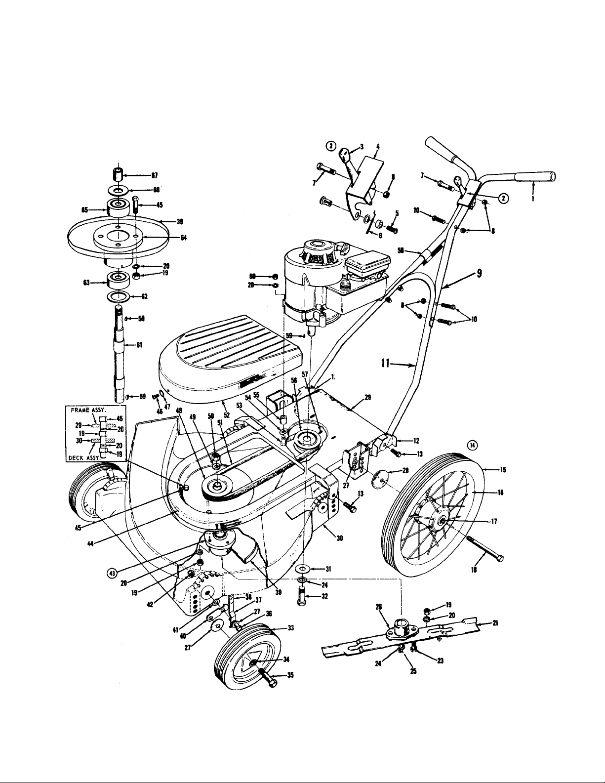
PARTS LIST FOR MODEL NO. 110-500
Raf.
No.
1
2 310-8846 Throttle Control - Complete
3
4 310-8841
5
6
7
8
9
10
11
12
13
14
15 734-237
16
17
18
19 712-123
20
21
23 710-117
24
25 710-113 HexHd. Cap Sew. 3/8—24 x 1-5/8 Ig.
26
27
28
79
30
31
32 710-152
33
34
35
Port
No.
305-7072
305-7470 Knob +
901-7627 Ferrule Assembly +
732-139
710-606
712-107 Hex Centerlock Nut 1/4—20 thread *
310-9364
710-106
310-8334
310-9060 Handle Bracket 46
710-209
501-9184 Wheel Assembly — Rear
734-238
748-147
738-114
736-119
312-8125
736-169
748-100 Blade Adapter
736-105
736-112
347-9169
347-9069
310-7386
SlO-9392
305-7006
738-213 Axle Bolt
Grips — White
Throttle Control Bracket + 38
Conduit and Wire +
HexHd. Cap Sew. 1/4-20 x 1-1/2 Ig. *
Handle — Upper (2 Req’d)
HexHd. Cap Sew. 1/4—20 x 1-1/4 Ig. * 44 712-526
Handle - Lower
Sems HexHd. Cap Sew. 3/8—16x5/8 Ig. *
Tire-Rib Tread 14” dia. x 1-3/4”
Wheel Assembly — Rear . Tire
Flange Bearing (2 Req’d Per Wheel)
Axle Bolt — Rear
Hex Nut 5/16 — 24 thread *
Spring Lockwasher 5/16 Screw *
Blade - 21”
HexHd. Cap Sew. 5/16—24 x 1 Ig.
(Heat Treated)
Spring Lockwasher — 3/8” Screw *
(Heat Treated)
Belleville Washer 63
Belleville Washer
Frame Assembly
Deck Assembly
Washer
HexHd. Cap Sew. 3/8—24 x 1 Ig.
Wheel Assembly — Front
Fortiflex Bearing
DESCRIPTION
Ref.
No.
36
37
39 347 -8809
40
41 736-133
42
43
45 710-116
47
48
49
50 712-922
51
52 347 -8295 Blade Soindle Cover
53 710-158
54 736-170
55
56 756-121
57 710-938
58 746-145
59
60
61
62 721-105
64
65 741-120
66 736-154
67
Port
No.
710-191
310-8835
305-7520
310-7492
712-116
901-7805
710-473
736-147
310-9925
736-921
754-116
711-250
714-365
712-267
711-240
741-107
719-120
711-212
Hex Hd. Cap Sew. 3/8-24 x 1-1/4 Ig.
(Heat Treated)
Sluing Lever Assembly
Knob - Red
Blade Reinforcement Plate
Wheel Pivot Bai
Flat Washer 3/8 ID *
Elastic Stop Nut 3/8—24 thread *
Blade Spindle Ass’y — Complete
Speed Nut
HexHd. Cap Sew. 5/16-18 x 2 Ig. *
Truss Hd. Mach. Sew. #10-24 x 1/2 Ig. *
External Lockwasher #10 Screw ♦
Pulley — 4” dia. — 1/2” bore
Spring Lockwasher — 1/2” screw *
Hex Jam Nut 1/2 — 20 thread ♦
V-Belt42” X 1/2” ♦
HexHd. Cap Sew. 5/16-24 x 1-1/4 Ig.
Lockwasher — Special
Spacer
Pulley — Engine — 4” dia.
Allen Set Sew. Cup Pt. 1/4—28 x 1/4 Ig.*
Cable Clip
Key-Hi Pro # HP 505 * A
Hex Nut 5/16-18 thread *
Spindle A
Seal A
Timken Bearing —3/4 Bore — lower A
Spindle Housing A
Timken Bearing — 11/16 Bore —upper A
Flat Washer A
Sleeve A
DESCRIPTION
* For faster service obtain standard nuts, bolts and washers locally. If these items cannot be obtained locally, order by
part number and size as shown on parts list.
+ Included in Part No. 310-8846 Control-Throttle (complete).
A Included in Part No. 901-7805 Blade Spindle Ass’y (complete).
ASSEMBLY
Your new mower is shipped completely assembled with the
exception of the handle.
1. Remove lawn mower and all parts from carton. Make
certain that all loose parts and literature are removed
from carton before carton is discarded.
2. Extend throttle control assembly, which is attached to
rear of mower and place on floor. CAUTION: Do not bend
or kink control wire.
3. (a) Snap lower handle into position on two lugs which
extend from the handle brackets mounted on the rear
of the frame assembly®
(b) Assemble the two upper handle parts with cap screws
and locknuts provided in parts bag. The yellow cap
screw should be used to attach throttle control assem
bly to upper handle as shown in diagram. Do not
tighten nuts.
(c) Attach upper handle assembly to lower handle with
cap screws and locknuts. Tighten all nuts.
(d) Secure control wire to lower handle with cable clips.
4. Check blade bolts for proper tightness.
5. See initial belt adjustment under Adjustment Section on
page U .
OPERATION
NOTE: For shipping purposes your mower is set with the
v/heels in a low cutting height position. For best results
raise the cutting position until it is determined which
height is best for your lawn. See adjustments.
1. Service engine with gas and oil. See Engine Manual pack
ed with lawn mower for complete instructions for the care
and maintenance of engine. Read Directions Carefully.
2. When ready to start engine, place throttle control lever,
on handle, in “Choke” position and start engine in
accordance with instructions in Engine Manual. After
engine starts, move throttle control lever, on handle, to
desired engine speed. The engine is stopped by placing
control lever on handle in the “Stop” position.
3. Be sure that lawn is clear of stones, sticks, wire or other
objects which could damage lawn mower or engine. For
best results and to insure more even grass distribution,
do not mow when lawn is excessively wet.
FORM NO. 770-2799C
Page 4

ADJUSTMENTS
CAUTION: Do not at any time make any adjustment to lawn
mower without first stopping engine and disconnecting spark
plug wire.
CUTTING HEIGHT - An adjusting plate and thumb lever at
each front wheel position provides cutting height adjustment.
Each adjusting plate has five holes. Height of cut will be
changed when the thumb lever is moved from one hole to
another. Simply depress thumb lever towards wheel and move
wheel and lever assembly to desired position. Cutting height
will be raised as lever is moved toward front and lowered as
lever is moved toward rear.
Adjustment may be made to the rear wheels by removing and
moving wheel studs to desired position. Cutting heists will
be raised as wheel studs are moved to a lower hole and
lowered as wheel studs are moved to a higher hole in the
deck. All wheels must be positioned in relative height of
cut positions.
THROTTLE - If adjustment becomes necessary, the throttle
control wire assembly can be reset as follows:
1. Loosen, but do not remove, screw securing throttle control
wire assembly at engine.
2. Move throttle control lever on handle to ‘“CHOKE”
position.
3. Move lever, to which control wire is fastened at engine,
to full choke position and retighten screw to secure
throttle control wire assembly.
BELT ADJUSTMENT - After the first one-half hour of
operation the slack in the belt must be taken up. After this
initial adjustment the belt will require only checking after
every 25 hours of operation. To tighten the belt, remove the
three truss head machine screws (46) and lockwashers (47)
and remove the blade spindle cover (52) Loosen the three
hex nuts (60) holding the engine to the frame assembly (29)
and pull the engine back until the belt (51) has a 1/4”
deflection when depressed by hand. Tighten the hex nuts
(60) and reassemble shroud.
MAINTENANCE
CUTTING BLADE - The blade may easily be removed for
grinding or replacement as follows:
1. Remove bolt and lock washer holding blade and hub
assembly to blade spindle.
2. Remove blade and hub assembly from blade spindle.
3. Remove two bolts, lock washers and nuts holding blade
to blade hub.
When sharpening blade, follow the original angle of grind as
a guide. It is extremely important that each cutting edge
receives an equal amount of grinding to prevent an unbalanced
blade. An unbalanced blade will cause excessive vibration
when rotating at high speeds and may cause damage to the
mower.
Upon reassembly, make certain all parts are assembled
properly and listened securely.
DECK - The underside of mower deck should be cleaned
after each period use as grass clippings, leaves, dirt and
other matter will accumulate. This accumulation of grass
clippings, etc., is undesirable as it will invite conosion and
may cause an uneven discharge of grass clippings at the
next cutting.
The deck may be cleaned by tilting the mower forward or on
its left side and scraping clean with a suitable tool or by
washing with a stream of water from a garden hose.
CAUTION: Do not direct the stream of water at a hot engine
as damage to the engine may result.
STORAGE - The following steps should be taken to prepare
lawn mower for storage.
1. Clean and lubricate mower thoroughly as described in the
preceding instructions.
2. Refer to Engine Manual for correct engine storage
instructions.
3. Coat mower’s cutting blade with chassis grease to prevent
rusting.
4. Place blocks under d’ck to raise tires clear of floor.
5. Store mower in a dry clean area.
LUBRICATION
IMPORTANT: Always stop engine and disconnect spark plug
wire before cleaning, lubricating or doing any kind of work on
lawn mower.
WHEELS - Front wheel bearings of Fortiflex require no
lubrication. Rear wheels of Lifetime graphoil bearings
require little lubrication. A light film of oil applied to these
bearings will reduce normal friction.
THROTTLE - Periodically lubricate throttle control lever
and throttle wire assembly with a few drops of light oil
(S.A.E. No. 10 or 20) for ease of operation.
ENGINE - Follow Engine Manual for lubrication instruction.
USING YOUR ROTARY MOWER
For best results do not cut wet grass because it tends to
stick to underside of the mower thus preventing proper
discharge of grass clippings. If wet grass must be cut reduce
engine speed and walking speed to help distribute the
clippings more effectively.
New grass should be treated as wet grass, otherwise a
normal walking speed is about the right pace for efficient
mowing.
The best mowing pattern is one that allows the clippings to
discharge towards the uncut part of the lawn. This permits
recutting of the clippings to further pulverize them. When
cutting high weeds, discharge towards cut portion then recut
at right angles to first direction.
Lawn should be cut in the fall as long as there is growth.
FORM NO. 770-27990
PRINTED IN U.S.A.
 Loading...