

Page 1

OWNEirS GUIDE
• ASSEMBLY • OPERATION • MAINTENANCE •
20" and 22"
ROTARY
MOWERS
Model Series
030 thru 062
Model 031A Shown
Important:
Read Safety Rules
and Instructions Carefully
WARNING: This unit is equipped with an internal combustion engine and should not be used
on or near any unimproved forest-covered, brush-covered or grass-covered land unless the
engine’s exhaust system is equipped with a spark arrester meeting applicable local or state
laws (if any). If a spark arrester is used, it should be maintained in effective working order by
the operator.
In the State of California the above is required by law (Section 4442 of the California Public
Resources Code). Other states may have similar laws. Federal laws apply on federal lands. A
in
AMERICA
spark arrester for the muffler is available through your nearest engine authorized service
dealer or contact the service department, RO. Box 368022, Cleveland, Ohio 44136-9722.
IMPORTANT!
Record the exact Model No. and Serial No.
which appear on the rear of your unit (on the
deck) in the space below. You must have these
numbers, along with the date of purchase, in
order to receive warranty or service.
FORM NO. 770-8550M
Page 2

IMPORTANT
THIS SYMBOL POINTS OUT IMPORTANT SAFETY INSTRUCTIONS WHICH, IF NOT FOLLOWED, COULD ENDANGER THE PERSONAL
SAFETY AND/OR PROPERTY OF YOURSELF AND OTHERS. READ AND FOLLOW ALL INSTRUCTIONS IN THIS MANUAL BEFORE
A
ATTEMPTING TO OPERATE YOUR LAWN MOWER. FAILURE TO COMPLY WITH THESE INSTRUCTIONS MAY RESULT IN PERSONAL
INJURY. WHEN YOU SEE THIS SYMBOL— ^
HEED ITS WARNING.
SAFE OPERATION PRACTICES
A
DANPFR' power equipmert, carelessness or error on the part of the operator can result in serious injury.
Your lawn mower was built o be operated according to the rules for safe operation in this manual As with
A
uHnucn. mower is capable of amputating hands and feet and throwing objects. Failure to observe the fol
lowing safety instructions cojid result in serious injury or death.
I. GENERAL OPERATION
1. Read this owner’s guide carefully in its entirety befo e attempt
ing to assemble this machine. Read, understand, an h follow all
instructions on the machine and in the manual(s) be ore opera
tion. Be completely familiar with the controls and the proper use
of this machine before operating it. Keep this manu i\ in a safe
place tor future and regular reference and for order! ig replace
ment parts.
2. Your rotary mower is a precision piece of power equ pment, not
a plaything. Therefore, exercise extreme caution a all times.
Your unit has been designed to perform one job: to now grass.
Do not use it for any other purpose.
3. Never allow children under 14 years old to opera e a power
mower. Children 14 years old and over should only operate
mower under close parental supervision. Only responsible indi
viduals who are familiar with these rules of safe operation
should be allowed to use your mower.
4. Keep the area of operation clear of all persons, narticularly
small children and pets. Stop engine when they are i i the vicin
ity of your mower to help prevent blade contact or thrown
object injury. Although the area of operation shou J be com
pletely cleared of foreign objects, an object may have been
overlooked and could be accidentally thrown by thi mower in
any direction and cause serious personal injury to the operator
or any others allowed in the area.
5. Thoroughly inspect the area where the equipment is ;o be used.
Remove all stones, sticks, wire, bones, toys and otier foreign
objects which could be picked up and thrown by th i mower in
any direction and cause serious personal injury to the operator
or any others allowed in the area. Plan your mowin( pattern to
avoid discharge of material toward roads, sidewalk;, bystand
ers and the like. To help avoid a thrown objects iijury, keep
children, animals, bystanders and helpers at least 7 j feet from
the mower while it is in operation.
6. Always wear safety glasses with side shields or safi ty goggles
during operation or while performing an adjustment n repair, to
protect eyes from foreign objects that may be throv n from the
machine in any direction.
7. Wear sturdy, rough-soled work shoes and close-fiUing slacks
and shirts. Shirts and pants that cover the arms ard legs and
steel-toed shoes are recommended. Do not wear I )ose fitting
clothes or jewelry. They can be caught in moving parts. Never
operate a unit in bare feet, sandals, or sneakers.
8. Do not put hands or feet near or under rotating parts Keep clear
of discharge opening at all times as the rotating blad' i can cause
injury.
9. Many injuries occur as a result of the mower being aulled over
the foot during a fall. Do not hang on to the mowe' if you are
falling; release the handle immediately.
10. Never pull the mower toward you while you are wal dng. If you
must back the mower away from a wall or obstructic n first look
down and behind, and then follow these steps:
a. Step back from the mower to fully extend your arms.
b. Be sure you are well balanced with sure footing.
c. Pull the mower back slowly, no more than half way toward
you.
d. Repeat these steps as needed.
II. Do not operate the mower while under the influenci of alcohol
or drugs.
12.
Disengage the self-propelled mechanism or drive clutch on
units so equipped before starting the engine.
13.
The blade control handle is a safety device. Never attempt to
bypass its operation. Doing so makes the safety device inopera
tive and may result in personal injury through contact with the
rotating blade. The blade control handle must operate easily in
both directions and automatically return to the disengaged posi
tion when released.
14.
Never operate the mower in wet grass. Always be sure of your
footing. A slip and fall can cause serious personal injury. Keep a
firm hold on the handle and walk, never run. Mow only in day
light or in good artificial light.
15.
Stop the blade when crossing gravel drives, walks or roads.
16.
If the equipment should start to vibrate abnormally, stop the
engine and check immediately for the cause. Vibration is gener
ally a warning of trouble.
17.
Shut the engine off and wait until the blade comes to a complete
stop before removing the grass catcher or unclogging the
chute. The cutting blade continues to rotate for a few seconds
after the engine is shut off. Never place any part of the body in
the blade area until you are sure the blade has stopped rotating.
18.
Never operate mower without proper guards, grass catcher,
plates or other safety protective devices in place.
19.
Muffler and engine become hot and can cause a burn. Do not
touch.
20
.
Only use accessories approved for this machine by the manu
facturer. Read, understand, and follow all instructions provided
with the approved accessory.
21.
If situations occur which are not covered in this manual, use
care and good judgment. Contact your dealer for assistance.
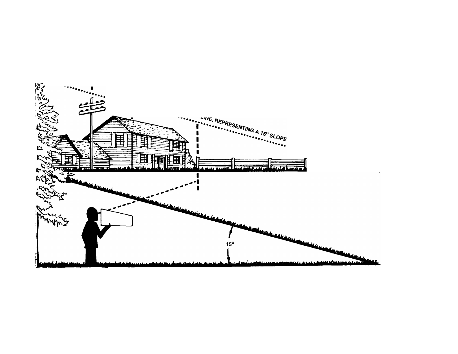
II. SLOPE OPERATION
, For your safety, use the slope gauge included as part of this manual
to measure slopes before operating this unit on a sloped or hilly
area. If the slope is greater than 15°. as shown on the slope gauge,
do not operate this unit on that area or serious injury could result.
DO:
• Mow across the face of slopes; never up and down. Exercise
extreme caution when changing direction on slopes.
• Watch for holes, ruts, hidden objects, or bumps. Tall grass can
hide obstacles.
• Always be sure of your footing. A slip and fall can cause serious
personal injury.
DO NOT:
• Do not mow near drop-offs, ditches or embankments. The opera
tor could loose footing or balance.
• Do not mow slopes greater than 15° as shown on the slope
gauge.
• Do not mow on wet grass. Reduced footing could cause slipping.
III. CHILDREN
' Tragic accidents can occur if the operator is not alert to the presence
of children. Children are often attracted to the mower and the mow
ing activity. Never assume that children will remain where you last
saw them.
1. Keep children out of the mowing area and under the watchful
care of a responsible adult other than the operator.
2. Be alert and turn mower off it a child enters the area.
Page 3

SAFE OPERATIONS PRACTICES (continued)
3. Before and while moving backwards, look behind and down for
small children.
4. Never allow children under age 14 to operate the mower.
5. Use extreme care when approaching blind corners, shrubs,
trees, or other objects that may obscure your vision of a child or
hazard.
IV. SERVICE
1. Use extreme care in handling gasoline and other fuels. They are
extremely flammable and the vapors are explosive.
a. Use only an approved container.
b. Never remove gas cap or add fuel while the engine is run
ning, Allow engine to cool at least two minutes before refuel
ing.
c. Replace gasoline cap securely and wipe off any spilled
gasoline before starting the engine as it may cause a fire or
explosion.
d. Extinguish ail cigarettes, cigars, pipes and other sources of
ignition.
e. Never refuel machine indoors because flammable vapors will
accumulate in the area.
f. Never store the machine or fuel container inside where there
is an open flame or spark such as a gas water heater, space
heater, or furnace.
2. Never run an engine inside a closed area.
3. To reduce fire hazard, keep mower free of grass, leaves, or other
debris build-up. Clean up oil or fuel spillage. Allow mower to
cool at least 5 minutes before storing.
4. Before cleaning, repairing, or inspecting, make certain the blade
and all moving parts have stopped. Disconnect the spark plug
wire, and keep the wire away from the spark plug to prevent
accidental starting.
5. Check the blade and engine mounting bolts at frequent intervals
for proper tightness. Also, visually inspect blade for damage
{e.g., bent, cracked). Replace with blade which meets original
equipment specifications.
6. Keep all nuts, bolts, and screws tight to be sure the equipment
is in safe working condition.
7. Never tamper with safety devices. Check their proper operation
regularly.
8. After striking a foreign object, stop the engine, remove the wire
from the spark plug, and thoroughly inspect the mower for any
damage. Repair the damage before starting and operating the
mower.
9. Never attempt to make a wheel or cutting height adjustment
while the engine is running.
10. Grass catcher components are subject to wear, damage and
deterioration, which could expose moving parts or allow objects
to be thrown. For safe^ protection, frequently check
components and replace with manufacturer’s recommended
parts, when necessary.
11. Mower blades are sharp and can cut. Wrap the blade(s) or wear
gloves, and use extra caution when servicing them.
12. Do not change the engine governor setting or overspeed the
engine. Excessive engine speeds are dangerous.
TO REDUCE THE RISK OF INJURY, DO NOT
OPERATE MOWER UNLESS REARTRAILING
SHIELD AND THIS GUARD OR ENTIRE
GRASS CATCHER IS IN ITS PROPER PLACE.
FIGURE 1.—Warning Label
A DANGER
AVOID SERIOUS INJURY OR DEATH
■ KEEP HANDS AND FEET AWAY FROM
ROTATING PARTS
> REMOVE OBJECTS THAT CAN BE THROWN
BY THE BLADE IN ANY DIRECTION.
WEAR SAFETY GLASSES
■ DO NOT MOW WHEN CHILDREN DR
OTHERS ARE AROUND.
■ USE EXTRA CAUTION ON SLOPES. DO NOT
MOW SLOPES GREATER THAN 15‘ MOW
ACROSS. NEVER UP AND DOWN NEVER
PULL MOWER CLOSE TO YOUR FEET LOOK
DOWN AND BEHIND BEFORE AND WHILE
READ OPERATOR'S MANUAL. KEEP SAFETY DEVICES (BLADE CONTROL,
TRAILING SHIELD. DISCHARGE COVER, ETC.) IN PLACE AND WORKING. |
MOVING BACKWARDS.
^ MAX 15
FIGURE 2.—Safe Operation Label
WARNING — YOUR RESPONSIBILITY
A
Restrict the use of this power machine to persons who read,
understand and follow the warnings and instructions in this
manual and on the machine.
Page 4
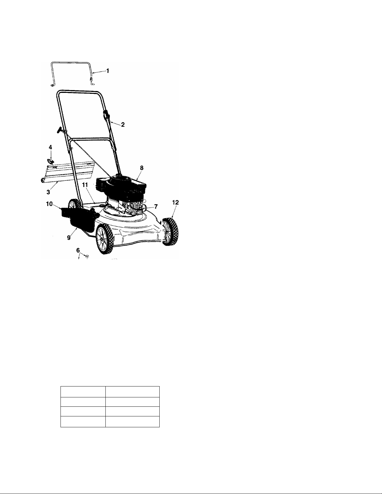
ASSORTED PARTS LIST
>'-5
Ref. No.
10
11
12
NOTE: Check engine oil level after filling.
Part No.
747-0824 Blade Control Handle
1
746-0552
2
746-0553 Brake Cable
746-0550 Brake Cable (060, 062)
731-0872A
3
731-1029
4
17098
5
742-0640t
742-0620tt
742-0642t
742-0622tt
6
753-0588t
753-0484tt
7
8
9
*
ic
731-1034 Chute Deflector
731-1035
777-1584
777-3540
**
Description
Brake Cable
(031,041,061)
(030, 040, 050)
Rear Guard Flap 20"
Rear Guard Flap 22"
Hinge Clip
Blade 20Blade 20Blade 22Blade 22Blade Adapter Kit 1
Blade Adapter Kit 1
J19LM-Spark Plug 1
Air Cleaner Element
(030-040)
Chute Deflector 1
(050-060)
Models 031-041-051* 21 oz
Danger—Cut Finger
Label
Danger Label/
1-800 Label
Wheel Assembly
Qty.
1
1
1
1
1
1
2
1
1
1
1
1
1
1
1
4
6-i
FIGURE 3,—Assorted Parts List
"^WHEEL CHART
Tread***
Rib 734-1168 (6")
Diamond
Diamond
Tread Type: Rib Diamond
Ass’y. Comp.
734-1779 (7")
734-1780 (8")
1-6
190-110-000 Grass Catcher
190-114-OOOf Mulch Kit
050/052
190-102-000tt Mulch Kit
050/052
190-115-000f Mulch Kit
060/061/062
190-100-000ft Mulch Kit
060/061/062
Blade secured with 1 bolt.
t
Blade secured with 3 bolts.
tt
See your engine service dealer.
WARNING
A
The only way to ensure the safe performance of your
product is to use original equipment parts, which are
designed and engineered to exacting specifications.
When you substitute, you take a chance on quality, reli
ability, safety and performance. Use original equipment
parts when repairing your mower.
Page 5
) ) )
----------------------------------------------------------------------------
Cut Along i ms Line--------------------------------------------------------------------------------------------
USE THIS SHEET AS A GUIDE TO DETERMINE SLOPES WHERE YOU MAY NOT OPERATE SAFELY.
SIGHT AND HOLD THIS LEVEL WITH A VERTICAL TREE
A POWER POLE
^----------------------------------- A CORNER OF A BUILDING
OR A FENCE POST
(D
"O
(0
0)
(D
(D
CO
...........................................
ui
WARNING
Ai
Do not mow on inclines with a slope in excess of 15 degrees (a rise of approximately 2-1/2 feet every 10 feet). A
riding mower could overturn and cause serious injury. If operating a walk-behind mower on such a slope, it is
extremely difficult to maintain your footing and you could slip, resulting in serious injury.
Operate RIDING mowers up and down slopes, never across the face of slopes.
Operate WALK-BEHIND mowers across the face of slopes, never up and down slopes.
0)
CO
<D
"O
0)
o
(D
c
c
CD
CD
CD
CD
3
o
CD
a
a
m
Page 6

CONTENTS OF HARDWARE PACK
Remove this sheet from your owner’s manual and lay the hardware on the illustration for identification purposes. After assembly,
keep the Slope Gauge which is on the reverse sice of this sheet for future use.
(Hardware pack may contain extra items whi :h are not used on your unit. Part numbers are shown in parentheses.)
ATTACHING THE
LOWER HANDLE
Cupped Wa shers
3/8" l.D.x7/r" O.D.
(736-01C 5)
*NOTE: Only 2 spacers required on
Model 030 and 040.
Spacers 3/8" I.D. x
78" O.D.
( '50-0910)
Hex Lock Nuts
3/8-24 Thread
(712-0355)
ATTACHING THE
B
UPPER HANDLE
ATTACHING THE
STARTER ROPE
Curved
Head
Bolts
(710-1250)
Rope
Guide
(710-1205)
Split Washers
5/16" I.D.
(736-0119)
Hex Nuts
5/16-18 Thread
(712-0267)
Hex Lock Nut
1/4-20 Thread
(712-0324)
O
c
>
o
SECURING THE CABLE
Q
U
INSTALLATION OF WHEELS
Axle Bolts
Qty. 4
(738-0533)
Cable Ties—Qty. 3
(726-0240)
______
3/8-16 Thread
f
Cupped Washers
3/8" I.D. X
1-1/8" O.D.
(736-0331)
Cupped
Washers
3/8" I.D. X
7/8" O.D.
(736-0105)
Hex Nuts —
(712-0798)
®©
0
INCHES
I I I I I I M I I I I I I I
Page 7

UNPACKING
TO REMOVE UNIT FROM CARTON
1. Remove staples, break glue on top flaps, or cut tape at
carton end and peel along top flap to open carton.
2. Remove loose parts if included with unit (i.e., owner’s
manual, etc.).
3. Cut along dotted lines and lay carton down flat.
4. Remove packing material.
5. Slide unit out of carton. Check carton thoroughly for
loose parts.
TOOLS REQUIRED FOR ASSEMBLY
(1) 1/2" Wrench
(2) 9/16" Wrenches
(1) Phillips Screwdriver
(1) 3/4" or Adjustable Wrench
(Two 6" Adjustable Wrenches may be used instead of the
above.)
DISCONNECT SPARK PLUG WIRE
Before setting up your lawn mower, disconnect the spark
plug wire from the spark plug, and ground it against the
engine. See figure 4.
ASSEMBLY INSTRUCTIONS
Spark
Plug
^ “V”Slot ^
on Engine \
Spark
Plug
Wire
Briggs & Stratton Engines
Retaining
Post
Spark Piug Wire
Tecumseh Engines
FIGURE 4.—Grounding the Spark Piug Wire
Spark
Piug
IMPORTANT; This unit is shipped WITHOUT GASOLINE
or OIL. After assembly, service engine with gasoline and
oil as instructed in the separate engine manual packed
with your unit.
NOTE: Reference to right or left hand side of the mower is
observed from the operating position.
This owner’s guide covers various models of mowers.
Follow only the instructions which pertain to your unit.
Cupped Washer
ATTACHING THE LOWER HANDLE (Hardware A)
Models 030 thru 041 only:
1. Raise the rear of the deck and block securely.
2. Model Series 040 only: Place the rear baffle in position
inside the rear of the deck. Use one axle bolt and hex nut
on each side of the rear of the deck to secure baffle
temporarily so you can attach the lower handle. See
figure 5A.
NOTE; Remove axle bolt and nut when assembling the
wheels, page 9.
3. Place one cupped washer on each hex bolt 1-1/2" long
(crowned side of washer goes against the head of the
hex bolt).
4. Insert the ends of the lower handle through the slots in
the rear of the deck.
NOTE: It is helpful to have another person hold the handle in
position as you continue.
5. Place one spacer between the bottom hole in lower
handle and forward hole in deck (model 030 series) or
— baffle (model 040 series). See figure 5A. Use a screw
driver to pry the handle away from the deck or baffle if
necessary.
6. Using a screwdriver, line up the forward hole in the deck
or baffle, the spacer and the bottom hole in the handle,
then insert hex bolt as shown from the outside of the
deck.
7. Secure with cupped washer (cupped side against the
handle) and hex lock nut. Do not tighten at this time.
8. Repeat steps 5 through 7 to attach the other side of the
handle.
9. Tighten both hex bolts and nuts securely.
Page 8

FIGURE 5B.—
Models 050 thru 062
ATTACHING THE LOWER HANDLE (Hardware A)
Models 050 thru 062 only:
1. Raise the rear of the deck and block securely.
2. Place one cupped washer on each hex bolt 1-1/2" long
(crowned side of washer goes against the head of the
hex bolt).
3. Insert the ends of the lower handle through the slots in
the rear of the deck.
NOTE: It is helpful to have another person hold the handle in
position as you continue.
4. Place two spacers between the bottom hole in lower
handle and bottom inside hole of the deck. See figure
— 5B. Use a screwdriver to pry the handle away from the
deck if necessary.
5. Using a screwdriver, line up the bottom inside hole in the
deck, the spacers and the bottom hole in the handle,
then insert hex bolt as shown from the outside of the
deck.
6. Secure with cupped washer (cupped side against the
handle) and hex lock nut. Do not tighten at this time.
7. Repeat steps 4 through 6 to attach the other side of the
handle.
8. Tighten both hex bolts and nuts securely.
T End
ATTACHING THE UPPER HANDLE (Hardware B1
1. Place the upper handle in position over the lower handle.
The hole in the side of the blade control handle (attached
to the upper handle) must be on the left side.
■ 2. Secure the upper handle to lower handle using the
curved head bolts, split washers and hex nuts as shown
in figure 6. The head of the carriage bolts go on the out
side of the handle.
ATTACHING THE CONTROL BOX
One end of the brake cable is attached to the engine. The
other end is attached to the control box. Attach the control
box to the upper handle as follows.
NOTE: If the control handle is disassembled from the upper
handle for any reason, assemble the control handle by
inserting the ends into the holes on each side of the upper
handle. The hole in the control handle must be on the left
side of the upper handle, and control handle must touch the
upper handle when engaged (squeezed against the upper
handle).
- 1. Remove the truss machine screw and hex lock nut from
the middle of the control box using a phillips screwdriver.
Place your finger over the hex lock nut to hold it inside
the control box so you can unscrew the truss machine
screw.
2. Make certain the blade control handle is on top of the
upper handle.
3. Route the control box (with cable attached) under the
lower handle.
Page 9

FIGURE 8.
End of
Control
Handle
Hex Lock
Nut
Truss
Machine
Screw
4. Holding the control box near the left side of the upper
handle (control box must be inside the handle), hook the
“Z” end of the brake cable into the control handle from
the outside to the inside. See figures 7 and 8.
5. Place the control box on the upper handle just below
(touching) the end of the control handle as shown in
— figure 8. Secure with hardware removed in step one by
placing hex lock nut into the indent on the inside of the
control box. Screw the truss machine screw into the hex
lock nut.
SECURING THE CABLE (Hardware D)
Secure the cable to the left side of the handle as follows.
WARNING: When attaching the control cable,
the cable must be routed to avoid contact with
A
1. Insert posts on cable ties into holes provided on the
— or outside of the handles. See figure 9A.
2. Secure the cable with the cable ties. See figure 9B. Trim
all sharp edges and hot surfaces to prevent
damage to the cable, which will render the con
trols inoperative.
inside of the handle, one on the upper handle and two on
the lower handle. The holes may be either on the inside
excess ends of cable ties.
Front Wheel Washer
Smaller Cupped
Use These Holes
For Front Wheel
INSTALLATION OF WHEELS (Hardware E)
The three holes provide three cutting heights for your mower.
Use the same hole location for all four wheels when
assembling. If wheels are to be assembled in the lowest cut
ting position (highest hole in the deck), refer to the note
below.
If your mower has two sets of holes (see figure 10), the front
wheels must be assembled in one of the three holes nearest
the front of the deck. The rear wheels must be assembled in
one of the three holes nearest the rear of the deck.
To assemble the wheels: (See figure 10)
1. Block up the mower securely.
2. Place axle bolt through wheel. (Hub side of wheel must
face deck.)
- 3. Place one smaller cupped washer on axle bolt, with the
cupped side of washer toward the deck (away from
wheel).
NOTE: If the lowest cutting position (highest hole in the deck)
is used, it is necessary to place the larger washer on the out
side of the deck and the smaller washer on the inside.
4. Secure wheel to deck with one larger cupped washer on
the inside of the deck (cupped side against the deck) and
hex nut. Tighten securely.
5. Assemble the other wheels in the same manner.
Remove the blocks.
Page 10
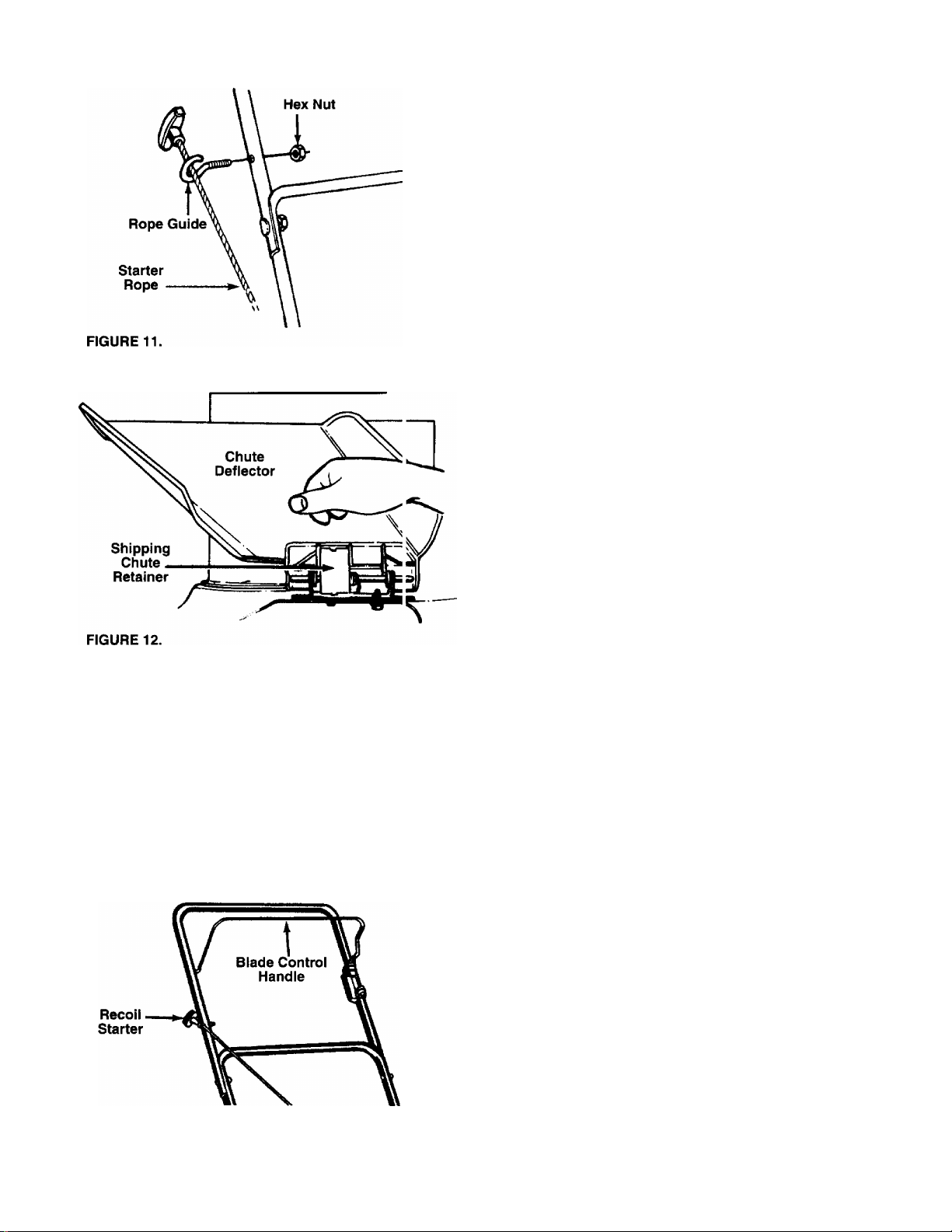
ATTACHING THE STARTER ROPE (Hardware C)
1. The Starter rope is inside the top of the engine. With the
spark plug wire disconnected and grounded, depress the
blade control handle and pull the rope out of the engine.
2. Place the rope guide around the starter rope, so the
opening in the rope guide is toward the front of the
mower as shown. Insert the rope guide into the right side
of the handle, and secure with hex lock nut. See figure
— 11.
FINAL ASSEMBLY OF MOWER
1. The chute deflector on your mower is held in an upright
position by a retainer for shipping purposes only. This
shipping retainer must be removed and discarded before
— the mower is put into operation. See figure 12.
To remove the shipping chute retainer, move the springloaded chute toward the engine by pushing above the
retainer. Remove the retainer and carefully lower the
chute into operating position, keeping fingers out of the
way.
2. Make certain all nuts and bolts are tightened securely.
FIGURE 13.
CONTROLS
BLADE CONTROL HANDLE
A
The blade control handle is located on the upper handle of
the mower. See figure 13. The blade control handle must be
depressed in order to operate the unit. Release the blade
control handle to stop the engine and blade.
A
RECOIL STARTER
The recoil starter handle is attached to the handle and is
used to start the engine. See figure 13.
10
WARNING: This control mechanism is a safety
device. Never attempt to bypass its operations.
WARNING: The blade will be rotating whenever
the engine is running.
Page 11

OPERATION
Keep hands and feet away from the chute area on cut
ting deck. See figure 1, warning label.
The operation of any lawn mower can result in foreign
objects being thrown into the eyes, which can result in
severe eye damage. Always wear safety
glasses or eye shields. We recommend
wide vision safety mask for over specta
cles or standard safety glasses.
GAS AND OIL FILL-UP
Service the engine with gasoiine and oil as instructed in
the separate engine manual packed with your mower. Read
instructions carefuiiy.
WARNING: Never fill fuel tank indoors, with
engine running or until the engine has been
A
TO START ENGINE AND ENGAGE BLADE
NOTE: Your engine is a constant speed engine, which is set
at full throttle for best performance.
1. Attach spark plug wire securely to spark plug.
2. Prime engine as instructed in the separate engine
3. Standing behind the unit, depress the blade control
4. Grasp starter handle and pull rope out slowly until engine
5. Pull rope with a rapid, continuous, full arm stroke. Keep a
allowed to cool for at least two minutes after
running.
manual.
handle and hold it against the upper handle as shown in
figure 14.
reaches start of compression cycle (rope will pull slightly
harder at this point). Let the rope rewind slowly.
firm grip on starter handle. Return it slowly to the rope
guide.
TO STOP ENGINE AND BLADE
1. Release the blade control handle to stop the engine and
blade.
WARNING: The blade continues to rotate for a
A
2. Disconnect the spark plug wire and ground it against the
USING YOUR ROTARY MOWER
Be sure that lawn is clear of stones, sticks, wire, or other
objects which could damage lawn mower or engine. Such
objects could be accidently thrown by the mower in any
direction and cause serious personal injury to the operator
and others.
For best results, do not cut wet grass because it tends to
stick to the underside of the mower, preventing proper dis
charge of grass clippings, and could cause you to slip and
fall. New grass or thick grass may require a narrower cut.
The best mowing pattern is one that allows the clippings to
discharge towards the uncut part of the lawn. This permits
recutting of the clippings to further pulverize them. When cut
ting high weeds, discharge towards cut portion, then recut at
right angles to first direction.
For a healthy lawn, never cut off more than one-third of
the total length of the grass. Lawn should be cut in the fall
as long as there is growth.
A
few seconds after the engine is shut off.
engine to prevent accidental starting while equipment is
unattended.
WARNING: If you strike a foreign object, stop
the engine. Remove wire from spark plug, thor
oughly inspect the mower for any damage, and
repair the damage before restarting and oper
ating the mower. Extensive vibration of the
mower during operation is an indication of
damage. The unit should be promptly
inspected and repaired.
ADJUSTMENTS
WARNING: Do not at any time make any
adjustment to lawn mower without first stop
A
ping engine and disconnecting spark plug
wire.
NOTE: If any problems are encountered, refer to the Trouble
Shooting Guide on page 13.
CUTTING HEIGHT ADJUSTMENT
Adjustment may be made by removing and moving axle bolts
to desired position. Cutting heights will be raised as axle
bolts are moved to a lower hole and lowered as axle bolts are
moved to a higher hole in the deck. All axle bolts must be
mounted in the same relative position. Cupped washers
must be assembled so that the cupped side of the washers
are against the deck. Refer to figure 10.
CARBURETOR ADJUSTMENTS
WARNING: If any adjustments are made to the
engine while the engine is running (e.g. carbu
A
11
retor), keep clear of all moving parts. Be care
ful of heated surfaces and muffler.
Page 12

Minor carburetor adjustment may be required to com
pensate for differences in fuel, temperature, altii ude and
load. Refer to the separate engine manual packed /vith your
mower for carburetor adjustment information.
NOTE: A dirty air cleaner will cause an engine to n 'n rough.
Be certain air cleaner is clean and attached to the c 3rburetor
before adjusting carburetor.
If the blade is secured to the blade adapter with two bolts,
remove the two small bolts, lock washers and nuts which
hold the blade to the adapter.
WARNING: Periodically Inspect the blade
adapter for cracks, especially if you strike a
A
foreign object. Replace when necessary.
LUBRICATION
WARNING: Always stop engine and dii connect
spark plug wire before cleaning, lubricating or
A
Blade Control—Lubricate the pivot points on the b ade con
trol handle and the brake cable at least once a se. ison with
light oil. See figure 15.The blade control must operate freely
in both directions.
FIGURE 15.
Chute Deflector—The torsion spring and pivot po nt should
be lubricated periodically with light oil to prevent a ly rust or
binding. Deflector must work freely.
Wheels—The wheels require no lubrication. Howe/er, if the
wheels are removed for any reason, lubricate the surface of
the axle bolt and the inner surface of the wheel wit i light oil.
Engine oil may also be used.
Engine—Follow engine manual for lubrication instr jctions.
doing any kind of work on lawn mowei.
Blade Control
Handle
Pivot Brake
Point Cable
MAINTENANCE
When sharpening the blade, follow the original angle of grind
as a guide. It is extremely important that each cutting edge
receives an equal amount of grinding to prevent an
unbalanced blade. An unbalanced blade will cause exces
sive vibration when rotating at high speeds, may cause dam
age to the mower and could break, causing personal injury.
The blade can be tested by balancing it on a round shaft
screwdriver. Remove metal from the heavy side until it bal
ances evenly. It is recommended that the blade always be
removed from the adapter for the best test of balance.
Before reassembling the blade and the blade adapter to the
unit, lubricate the engine crankshaft and the inner surface of
the blade adapter with light oil (or engine oil). Lubricating the
bolt holes, bolts and inner surface of the nuts is also recom
mended.
THREE BOLT BLADE MOUNTING
Install the blade to the blade adapter with the side of the
blade marked “bottom” (or with part number) facing away
from the adapter. Refer to figure 16. insert two hex bolts up
through the blade and adapter and secure with lock washers
and hex nuts. Tighten according to “Blade Mounting Torque”
section below.
Place the blade and blade adapter assembly on the engine
crankshaft.
NOTE: If the adapter is keyed, make sure the key in the
adapter is aligned with the key slot on the crankshaft.
WARNING: Be sure to disconnect anc ground
the spark plug wire before perfornring any
A
NOTE: When tipping the unit, empty the fuel tank and keep
engine spark plug side up.
TROUBLE SHOOTING
Refer to page 13 of this manual for trouble shootinji informa
tion.
CUniNG BLAOE
When removing the cutting blade for sharpening o ■ replace
ment, protect hands by using heavy gloves or a rail to grasp
the cutting blade. Remove the bolt and blade supp )rt or bell
washer which hold the blade and adapter to the engine
crankshaft. Remove the blade and adapter from t le crank
shaft.
repairs or maintenance.
FIGURE 16.—Three Bolt Blade Mounting
12
Page 13
Place the bell washer on the hex nut with the crowned side of
the bell washer against the head of the bolt (see inset of bell
washer). Insert the hex bolt and bell washer assembly
through the blade and blade adapter and tighten the hex bolt
to the torque listed in the “Blade Mounting Torque” section
below.
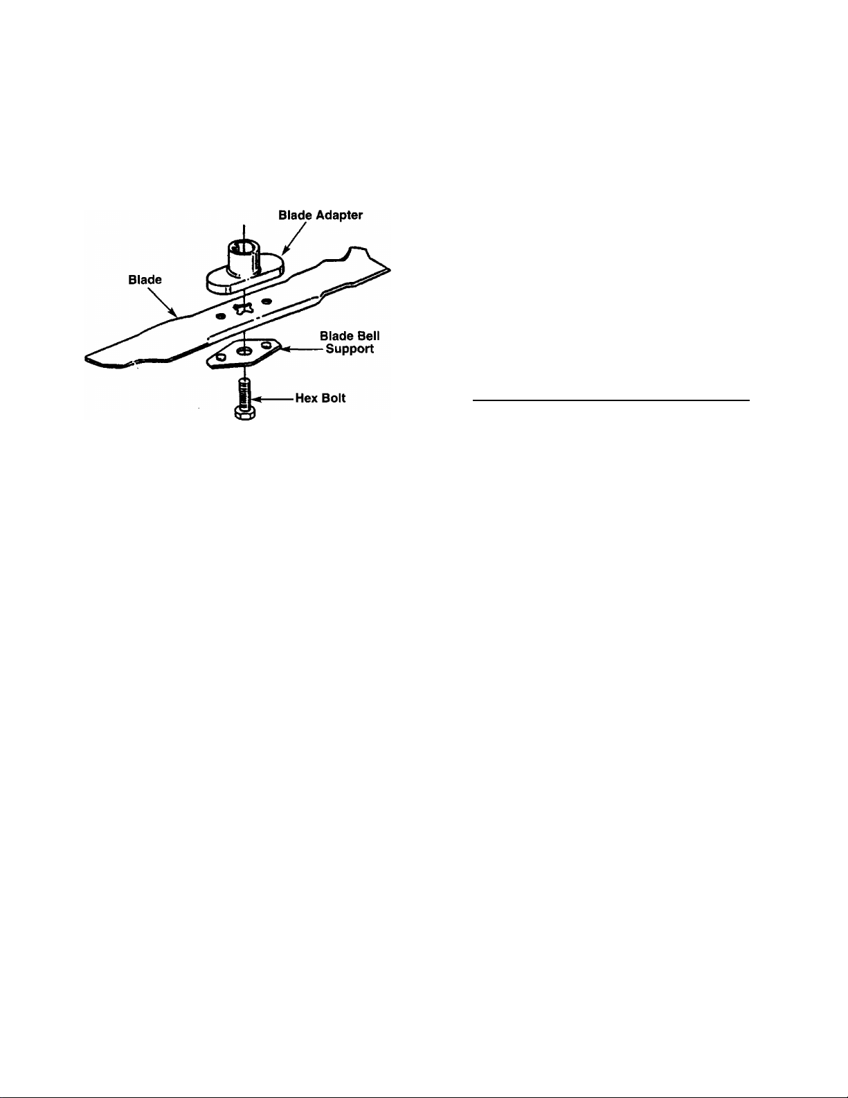
FIGURE 17,—One Bolt Blade Mounting
SINGLE BOLT BLADE MOUNTING
Install the blade adapter on the crankshaft with the “star”
away from the engine. Refer to figure 17. Place the blade
with the side marked bottom (or with part number) facing
away from the adapter. Align the blade bell support over the
blade with the tabs in the hoies of the blade and insert the
hex bolt. Tighten the hex bolt to the torque listed in the “Blade
Mounting Torque” section below.
Blade Mounting Torque
Center Bolt: 450 in. lbs. min., 600 in. lbs. max.
Blade Adapter Bolts (if applicable): 200 in. lbs. min., 350 in.
lbs. max.
To ensure safe operation of your unit, all nuts and bolts must
be checked periodically for correct tightness.
Service air cleaner every 25 hours under norma! conditions.
Clean every few hours under extremely dusty conditions.
Poor engine performance and flooding usually indicates that
the air cleaner should be serviced. To service the air cleaner,
refer to the separate engine manual packed with your unit.
The spark plug should be cleaned and the gap reset once a
season. Spark plug replacement is recommended at the
start of each mowing season; check engine manual for
correct plug type and gap specifications.
Clean the engine regularly with a cloth or brush. Keep the
cooling system (blower housing area) clean to permit proper
air circulation which is essential to engine performance and
life. Be certain to remove all grass, dirt and combustible
debris from muffler area.
OFF-SEASON STORAGE
The following steps should be taken to prepare lawn mower
for storage.
1. Clean and lubricate mower thoroughly as described in
the lubrication instructions.
2. Refer to engine manual for correct engine storage
instructions.
3. Coat mower’s cutting blade with chassis grease to
prevent rusting.
4. Store mower in a dry, clean area. Do not store next to
corrosive materials, such as fertilizer.
NOTE: When storing any type of power equipment in an
unventilated or metal storage shed, care should be taken to
rust-proof the equipment. Using a light oil or silicone, coat
the equipment, especially cables and all moving parts.
DECK
The underside of the mower deck should be cleaned after
each use to prevent a buildup of grass clippings, leaves, dirt
or other matter. If this debris is allowed to accumulate, it wilt
invite rust and corrosion, and may cause an uneven dis
charge of grass clippings at the next cutting.
The deck may be cleaned by tilting the mower and scraping
clean with a suitable tool (make certain the spark plug wire is
disconnected).
ENGINE
Refer to the separate engine manual for engine mainte
nance instructions.
Maintain engine oil as instructed in the separate engine
manual packed with your unit. Read and follow instructions
carefully.
13
Page 14

TROUBLE SHOOTING GUIDE
Trouble
Engine fails to start
Engine runs erratic
Engine overheats
Occasional skip
(hesitates) at high speed
Idles poorly
Excessive vibration
Mower will not
discharge grass
Uneven cut 1. Wheels not positiot ed correctly.
Possible Cause(s)
1. Blade control hand e disengaged.
2. Spark plug wire dis connected.
3. Fuel tank empty, oi stale fuel.
4. Blocked fuel line (if so equipped).
5. Faulty spark plug.
6. Engine flooded.
1. Spark plug wire loc se.
2. Blocked fuel line (if so equipped)
or stale fuel.
3. Vent in gas cap plu 3ged.
4. Water or dirt in fuel system.
5. Dirty air cleaner.
6. Carburetor out of a ijustment.
1. Engine oil level low
2. Air flow restricted.
3. Carburetor not adjt sted properly.
1. Spark plug gap too close.
2. Carburetor idle mix ure adjustment
improperly set.
1. Spark plug fouled, aulty or gap too wide.
2. Carburetor impropt riy adjusted.
3. Dirty air cleaner.
1. Cutting blade loose or unbalanced.
2. Bent cutting blade.
1. Engine speed too !■ w.
2. Wet grass.
3. Excessively high gt ass.
2. Dull blade.
Corrective Action
1. Engage blade control handle.
2. Connect wire to spark plug.
3. Fill tank with clean, fresh gasoline.
4. Clean fuel line.
5. Clean, adjust gap or replace.
6. Crank engine with throttle (if so equipped)
in OFF position.
1. Connect and tighten spark plug wire.
2. Clean fuel line; fill tank with clean,
fresh gasoline.
3. Clear vent.
4. Drain fuel tank. Refill with fresh fuel.
5. Clean air cleaner.t
6. Adjust carburetor.t
1. Fill crankcase with proper oil.
2. Remove blower housing and clean.t
3. Adjust carburetor.t
1. Adjust gap to .030”.
2. Adjust carburetor.t
1. Reset gap to .030" or replace spark plug.
2. Adjust carburetor.t
3. Clean air cleaner.f
1. Tighten blade and adapter. Balance blade.
2. Replace blade.
1. Set throttle between 3/4 and full throttle.
2. Do not mow when grass is wet; wait
until later to cut.
3. Mow once at a high cutting height, then
mow again at desired height or make a
narrower cutting swath (1/2 width).
1. Place all four wheels in same height position.
2. Sharpen or replace blade.
tRefer to separate engine manual packed with your unit.
Note: For repairs beyond the minor adjustments listed abo ^e,
please contact your local authorized service dealer.
14
Page 15

For Parts, Acce
ssohes or Service Information,
Call 1 -
800-800-7310
Model Number
Serial Number
□□□□□□□□□□a
Product Number
□□□□□□□□□□a
A
you take a chance on
quality, reliability, safety
and performance.
\A/ARMIMO" Engine Exhaust from this product contains chemicals known to the
VV/Aril\l IIMVJ ■ of California to cause cancer, birth defects or other reproductive harm.
 Loading...