

Page 1

MTC-1
MANUAL AIR CONDITIONER
J AIR CONDITIONER
CONTENTS
C
D
E
F
G
H
I
K
L
M
SECTION
A
B
MTC
Revision: January 2005 2004 Quest
PRECAUTIONS .......................................................... 5
Precautions for Supplemental Rest raint System
(SRS) “AIR BAG” and “SEAT BELT PRE-TEN-
SIONER” .................................................................. 5
Precautions for Working with HFC-134a (R-134a) ..... 5
Contaminated Refrigerant ........................................ 5
General Refrigerant Precautions .............................. 6
Precautions for Leak Detection Dye ......................... 6
A/C Identification Label ............................................ 7
Precautions for Refrigerant Connection ................... 7
FEATURES OF NEW TYPE REFRIGERANT
CONNECTION ................................ ...................... 7
O-RING AND REFRIGERANT CONNECTION ..... 8
Precautions for Servicing Compressor ....................11
Precautions for Service Equipment .........................11
RECOVERY/RECYCLING EQUIPMENT .............11
ELECTRONIC LEAK DETECTOR .......................11
VACUUM PUMP ................................................. 12
MANIFOLD GAUGE SET .................................... 12
SERVICE HOSES ............................................... 12
SERVICE COUPLERS ........................................ 13
REFRIGERANT WEIGHT SCALE ...................... 13
CHARGING CYLINDER ...................................... 13
Wiring Diagrams and Trouble Diagnosis ................ 13
PREPARATION ......................................................... 14
Special Service Tools ............................................. 14
HFC-134a (R-134a) Service Tools and Equipment ... 14
Commercial Service Tools ...................................... 16
REFRIGERATION SYSTEM ....................... ....... ....... 18
Refrigerant Cycle ................................................... 18
REFRIGERANT FLOW ....................................... 18
Refrigerant System Protection ............................... 18
REFRIGERANT PRESSURE SENSOR ............. 18
PRESSURE RELIEF VALVE .............................. 19
Component Layout ................................................. 20
FRONT REFRIGERATION SYSTEM .................. 20
REAR REFRIGERATION SYSTEM .................... 21
LUBRICANT ................................ ................... ........... 22
Maintenance of Lubricant Quantity in Compressor ...22
LUBRICANT ........................................................ 22
CHECKING AND ADJUSTING ............................ 22
AIR CONDITIONER CONTROL ...............................24
Description ................... ...... ....... ...... ........................ 24
Operation .............. ................................. ................. 24
AIR MIX DOOR CONTROL ................................. 24
BLOWER SPEED CONTROL ............................. 24
INT AKE DOORS CONTROL ............................... 24
MODE DOOR CONTROL ................................... 24
DEFROSTER DOOR CONTROL ........................ 24
MAGNET CLUTCH CONTROL ........................... 25
SELF-DIAGNOSTIC SYSTEM ........... ...... ....... ....25
Description of Control System ................................26
Control Operation ................................................... 26
DISPLAY SCREEN ..............................................27
TEMPERATURE DIAL (TEMPERATURE CON-
TROL) (FRONT) ..................................................27
TEMPERATURE DIAL (TEMPERATURE CON-
TROL) (REAR) .................................................... 27
RECIRCULATION () SWITCH .............................27
REAR WINDOW DEFOGGER SWITCH ............. 27
OFF DIAL (BLOWER SPEED SET TO 0) ........... 27
A/C SWITCH ....................................................... 27
MODE DIAL ......................................................... 27
FRONT BLOWER CONTROL DIAL .................... 27
REAR BLOWER CONTROL DIAL ...................... 27
Discharge Air Flow .................................................28
FRONT ................................................................ 28
REAR ..................................................................28
System Description .................................................29
SWITCHES AND THEIR CONTROL FUNCTION ...29
CAN Communication System Description .............. 30
TROUBLE DIAGNOSIS ............................................ 31
CONSULT-II Function (BCM) ............................. ....31
CONSULT-II BASIC OPERATION .......................31
DATA MONITOR .................................................32
How to Perform Trouble Diagnosis for Quick and
Accurate Repair ......................................................33
Page 2

MTC-2
Revision: January 2005 2004 Quest
WORK FLOW ......................................................33
SYMPTOM TABLE ..............................................33
Component Parts and Harness Connector Location ...35
ENGINE COMPARTMENT ........................... ....... 35
FRONT PASSENGER COMPARTMENT ............36
REAR PASSENGER COMPARTMENT ............... 37
Schematic ................. ..............................................38
Wiring Diagram —A/C,M— ..................................... 39
Front Air Control Terminals and Reference Value ... 48
PIN CONNECTOR TERMINAL LAYOUT ............48
TERMINALS AND REFERENCE VALUE FOR
FRONT AIR CONTROL ....................................... 48
A/C System Self-diagnosis Function ......................50
DESCRIPTION ....................................................50
Operational Check ..................................................52
CHECKING BLOWER .........................................52
CHECKING DISCHARGE AIR ............................52
CHECKING RECIRCULATION ............................52
CHECKING TEMPERATURE DECREASE .........53
CHECKING TEMPERATURE INCREASE ..........53
CHECK A/C SWITCH ..........................................53
Power Supply and Ground Circuit for Front Air Con-
trol ............................. .......................... .................... 54
INSPECTION FLOW ...........................................54
COMPONENT DESCRIPTION ............................55
DIAGNOSTIC PROCEDURE FOR A/C SYSTEM ...55
Mode Door Motor Circuit ........................................57
INSPECTION FLOW ...........................................57
SYSTEM DESCRIPTION .................................... 58
COMPONENT DESCRIPTION ............................58
DIAGNOSTIC PROCEDURE FOR MODE
DOOR MOTOR ...................................................58
Air Mix Door Motor Circuit ......................................61
INSPECTION FLOW ...........................................61
SYSTEM DESCRIPTION .................................... 62
COMPONENT DESCRIPTION ............................62
DIAGNOSTIC PROCEDURE FOR AIR MIX
DOOR MOTOR (FRONT) ....................................62
DIAGNOSTIC PROCEDURE FOR AIR MIX
DOOR MOTOR (REAR) ......................................64
Intake Door Motor Circuit ........................................ 67
INSPECTION FLOW ...........................................67
SYSTEM DESCRIPTION .................................... 68
COMPONENT DESCRIPTION ............................68
DIAGNOSTIC PROCEDURE FOR INTAKE
DOOR MOTOR (DRIVER) ...................................68
DIAGNOSTIC PROCEDURE FOR INTAKE
DOOR MOTOR (PASSENGER) ..........................69
Defroster Door Motor Circuit ............................ .......70
SYMPTOM: ...................................... ...... ....... .......70
INSPECTION FLOW ...........................................70
SYSTEM DESCRIPTION .................................... 71
COMPONENT DESCRIPTION ............................71
DIAGNOSTIC PROCEDURE FOR
DEFROSTER DOOR MOTOR ............................71
Front Blower Motor Circuit ...................................... 72
INSPECTION FLOW ...........................................72
SYSTEM DESCRIPTION .................................... 73
DIAGNOSTIC PROCEDURE FOR BLOWER
MOTOR .................................. ............. ............. ....74
COMPONENT INSPECTION ...............................78
Rear Blower Motor Circuit .......................................80
INSPECTION FLOW ....... ....... ...... ....... ...... ...........80
SYSTEM DESCRIPTION .....................................81
DIAGNOSTIC PROCEDURE FOR REAR
BLOWER MOTOR ...............................................81
COMPONENT INSPECTION ...............................89
Rear Air Control Circuit ...........................................91
INSPECTION FLOW ....... ....... ...... ....... ...... ...........91
SYSTEM DESCRIPTION .....................................92
DIAGNOSTIC PROCEDURE FOR REAR AIR
CONTROL ...........................................................92
Magnet Clutch Circuit ..............................................94
INSPECTION FLOW ....... ....... ...... ....... ...... ...........94
SYSTEM DESCRIPTION .....................................95
DIAGNOSTIC PROCEDURE FOR MAGNET
CLUTCH ..............................................................95
COMPONENT INSPECTION ...............................99
Insufficient Cooling ................................................100
INSPECTION FLOW ....... ....... ...... ....... ...... .........100
PERFORMANCE TEST DIAGNOSES ..............101
PERFORMANCE CHART ..................................104
TROUBLE DIAGNOSES FOR UNUSUAL PRES-
SURE .............................. ...................................105
Insufficient Heating ...............................................108
INSPECTION FLOW ....... ....... ...... ....... ...... .........108
Noise ............................ .........................................109
INSPECTION FLOW ....... ....... ...... ....... ...... .........109
Self-diagnosis .......................................................110
INSPECTION FLOW ....... ....... ...... ....... ...... .........110
Ambient Sensor Circuit ......................................... 111
COMPONENT DESCRIPTION .......................... 111
AMBIENT TEMPERATURE INPUT PROCESS .111
DIAGNOSTIC PROCEDURE FOR AMBIENT
SENSOR ......................... ................................... 111
COMPONENT INSPECTION .............................113
Intake Sensor Circuit .............................................113
COMPONENT DESCRIPTION ..........................113
DIAGNOSTIC PROCEDURE FOR INTAKE SEN-
SOR ...................................................................113
COMPONENT INSPECTION .............................115
CONTROL UNIT .......................... ...... ....... ...... ....... ..116
Removal and Installation .......................................116
FRONT AIR CONTROL .....................................116
REAR AIR CONTROL .......................................116
AMBIENT SENSOR ................................................117
Removal and Installation .......................................117
INTAKE SENSOR .............................. ....... ...... ....... ..118
Removal and Installation .......................................118
REMOVAL ........................................................ ..118
INSTALLATION ......... .........................................118
BLOWER MOTOR ...................................................119
Removal and Installation .......................................119
FRONT BLOWER MOTOR ................................119
REAR BLOWER MOTOR ..................................120
Page 3

MTC-3
C
D
E
F
G
H
I
K
L
M
A
B
MTC
Revision: January 2005 2004 Quest
IN-CABIN MICROFILTER ....................................... 121
Removal and Installation ...................................... 121
FUNCTION ...................................... ............. ..... 121
REPLACEMENT TIMING .................................. 121
REPLACEMENT PROCEDURES ..................... 121
HEATER & COOLING UNIT ASSEMBLY .............. 122
Components ................................ ......................... 122
Removal and Installation ...................................... 123
FRONT HEA TER AND COOLING UNIT ASSEM-
BLY .................................................................... 123
REAR HEATER AND COOLING UNIT ASSEM-
BLY .................................................................... 124
HEATER CORE ....................... ...... ....... ...... ....... ..... 125
Components ................................ ......................... 125
Removal and Installation ...................................... 126
FRONT HEATER CORE ................................... 126
REAR HEATER CORE ..................................... 127
HEATER PUMP ....................... ...... ....... ...... ....... ..... 128
Removal and Installation ...................................... 128
REMOVAL ......................................................... 128
INSTALLATION ................................................. 128
DEFROSTER DOOR MOTOR ................................ 129
Removal and Installation ...................................... 129
REMOVAL ......................................................... 129
INSTALLATION ................................................. 129
INTAKE DOOR MOTOR ......................................... 130
Components ................................ ......................... 130
Removal and Installation ...................................... 131
DRIVER SIDE ................................................... 131
PASSENGER SIDE ........................................... 132
MODE DOOR MOTOR ........................................... 133
Removal and Installation ...................................... 133
REMOVAL ......................................................... 133
INSTALLATION ................................................. 134
AIR MIX DOOR MOTOR ......................................... 135
Components ................................ ......................... 135
Removal and Installation ...................................... 135
AIR MIX DOOR MOTOR (FRONT) ................... 135
AIR MIX DOOR MOTOR (REAR) ..................... 136
FRONT BLOWER MOTOR RESISTOR ................. 137
Removal and Installation ...................................... 137
REMOVAL ......................................................... 137
INSTALLATION ................................................. 137
REAR BLOWER MOTOR RESISTOR ................... 138
Removal and Installation ...................................... 138
REMOVAL ......................................................... 138
INSTALLATION ................................................. 138
DUCTS AND GRILLES .......................................... 139
Components .........................................................139
Removal and Installation ......................................142
DEFROSTER NOZZLE .....................................142
FRESH AIR DUCT ............................................142
DEFROSTER DUCT .........................................142
RH AND LH SIDE DEMISTER DUCT ...............142
RH, LH, AND CENTER VENTILATOR DUCT ...142
FLOOR CONNECTOR DUCT ...........................142
FLOOR DISTRIBUTION DUCT .........................142
FLOOR DUCT ...................................................142
REAR OVERHEAD DUCT ................................142
REAR FLOOR DUCT ............................... ....... ..142
GRILLES ...........................................................143
REFRIGERANT LINES ...........................................144
HFC-134a (R-134a) Service Procedure ...............144
SETTING OF SERVICE TOOLS AND EQUIP-
MENT ................................................................144
Components .........................................................146
Removal and Installation for Compressor ............148
REMOVAL .........................................................148
INSTALLATION .................................................148
Removal and Installation for Compressor Clutch .149
REMOVAL .........................................................149
INSPECTION ....................................................150
INSTALLATION .................................................150
BREAK-IN OPERATION ....................................152
Removal and Installation for Low-pressure Flexible
Hose .....................................................................152
REMOVAL .........................................................152
INSTALLATION .................................................152
Removal and Installation for High-pressure Flexible
Hose .....................................................................152
REMOVAL .........................................................152
INSTALLATION .................................................152
Removal and Installation for High-pressure Pipe .153
REMOVAL .........................................................153
INSTALLATION .................................................153
Removal and Installation for High/Low-pressure
Pipe ......................................................................153
REMOVAL .........................................................153
INSTALLATION .................................................153
Removal and Installation for Refrigerant Pressure
Sensor ..................................................................153
REMOVAL .........................................................153
INSTALLATION .................................................153
Removal and Installation for Condenser ..............154
REMOVAL .........................................................154
INSTALLATION .................................................154
Removal and Installation for Front Evaporator .....155
REMOVAL .........................................................155
INSTALLATION .................................................156
Removal and Installation for Rear Evaporator ......157
REMOVAL .........................................................157
INSTALLATION .................................................158
Removal and Installation for Front Expansion Valve .158
REMOVAL .........................................................158
INSTALLATION .................................................158
Removal and Installation for Rear Expansion Valve .158
REMOVAL .........................................................158
Page 4

MTC-4
Revision: January 2005 2004 Quest
INSTALLATION ......................... ............. ............158
Checking for Refrigerant Leaks ............................159
Checking System for Leaks Using the Fluorescent
Dye Leak Detector .......... ....... ...... ....... ...... ............159
Dye Injection ....... ...... ...... ......................................159
Electronic Refrigerant Leak Detector ....................160
PRECAUTIONS FOR HANDLING LEAK
DETECTOR .............................. .........................160
CHECKING PROCEDURE ................................161
SERVICE DATA AND SPECIFICATIONS (SDS) ....163
Service Data and Specifications (SDS) ................163
COMPRESSOR .............. ...................................163
LUBRICANT .................... ............. ............. .........163
REFRIGERANT .................................................163
ENGINE IDLING SPEED ...................................163
BELT TENSION .................................. ...... ....... ..163
Page 5

PRECAUTIONS
MTC-5
C
D
E
F
G
H
I
K
L
M
A
B
MTC
Revision: January 2005 2004 Quest
PRECAUTIONS PFP:00001
Precautions for Supplemental Restraint System (SRS) “AIR BAG” and “SEAT
BELT PRE-TENSIONER”
EJS001RK
The Supplemental Rest raint System such as “AIR BAG” and “SEAT BELT PR E-TENSIONER”, used along
with a front seat belt, helps to reduce the risk or severity of injury to the driver and front passenger for certain
types of collision. This system includes seat belt switch inputs and dual stage front air bag modules. The SRS
system uses the seat belt switches to determine the front air bag deployment, and may only deploy one front
air bag, depending on the severity of a collision and whether the front occupants are belted or unbelted.
Information necessary to service the system safely is included in the SRS and SB section of this Service Manual.
WARNING:
● To avoid rendering the SRS inopera tive, whi ch could incr ease the risk of pe rsonal injury or death
in the event of a collision which would result in air bag inflation, all maintenance must be performed by an authorized NISSAN/INFINITI dealer.
● Improper maintenance, inc luding incorrect removal and installation of the SRS, can lead to per-
sonal injury ca use d by unintentional ac tiv atio n o f the system. For remo va l of Spiral Cable and Air
Bag Module, see the SRS section.
● Do not use electrical test equ ipment o n any circu it related to the SRS unless in structed to in this
Service Manual. SRS wiring harnesses can be identified by yellow and/or orange harnesses or
harness connectors.
Precautions for Working with HFC-134a (R-134a) EJS001RL
WARNING:
● CFC-12 (R-12) refrigerant and HFC-13 4a (R-1 34a) refrige rant are not com patible. If the refrigera nts
are mixed compressor failure is likely to occur. Refer MTC-5, "
Contaminated Refrigerant" . To
determine the purity of HFC-134a (R-134a) in the vehicle and recovery tank, use Refrigerant
Recovery/R ecycling Recharging equipment and Refrigerant Identifier.
● Use only specified lubricant for the HFC-134a (R-134a) A/C system and HFC-134a (R-134a) compo-
nents. If lubricant other than that specified is used, compressor failure is likely to occur.
● The specified HFC-134a (R-134a) lubricant rapidly absorbs moisture from the atmosphere. The fol-
lowing handling precautions must be observed:
– When removing refrig erant components from a vehicl e, immediately cap (s eal) the component to
minimize the entry of moisture from the atmosphere.
– When installing refrigera nt components to a vehicle, do not r emove the caps (unseal) until just
before connecting the com ponen ts. Connect all refrigeran t loop compo nents as quickly as poss ible to minimize the entry of moisture into system.
– Only use the specified lubricant from a sealed container. Immediately reseal containers of lubri-
cant. Without proper sealing, lubricant will become moisture saturated and should not be used.
– Avoid breathing A/C refrigerant and lubrica nt vapo r or mist. Ex posure may irritate eyes, nose a nd
throat. Remo ve HF C -13 4a ( R- 13 4a ) f ro m t he A /C sy ste m u si n g ce r ti fie d se r vice e qu i pm ent m ee tin g
requirements of SAE J2210 [HFC-134a (R-134a) recycling equipment] or J2209 [HFC-134a (R-134a)
recycling equipment]. If accidental system discharge occurs, ventilate work area before resuming
service. Additional health an d safety information may be obtained from refrigerant a nd lubricant
manufacturers.
– Do not allow refrigerant lubricant to come in contact with styrofoam parts. Damage may result.
Contaminated Refrigerant EJS001RM
If a refrigerant other than pure HFC-134a (R-134a) is identified in a vehicle, your options are:
● Explain to the customer that environmental regulations prohibit the release of contaminated refrigerant
into the atm osphere.
● Explain that recov ery of the con taminated refrig erant cou ld dama ge your serv ice equi pment and re friger-
ant supply.
● Suggest the cust omer return the v ehic le t o t he lo cation of prev ious servic e w here the c ontami natio n may
have occurred.
● If you choose t o per form the re p air, recover the re frige ran t usin g onl y dedicated equipment and contain-
ers. Do not recover contaminated refrigerant into your existing service equipment. If your facility
Page 6

MTC-6
PRECAUTIONS
Revision: January 2005 2004 Quest
does not have de dicat ed re cover y equi pmen t, you ma y cont ac t a loc al ref rig erant produ ct ret ai ler f or avai lable service. This refrigerant must be disposed of in accordance with all federal and local regulations. In
addition, replacement of all refriger ant system components on the vehicle is recommended.
● If the vehicle is within the warranty period, the air conditioner warranty is void. Please contact Nissan Cus-
tomer Affairs for further assistance.
General Refrigerant Precautions EJS001RN
WARNING:
● Do not release refrigerant into the air. Use approved recover y/recycling equipment to capture the
refrigerant every time an air conditioning system is discharged.
● Always wear eye and hand protectio n (goggles and glov es) when workin g with any refrigerant o r
air conditioning system.
● Do not store or heat refrigerant containers above 52°C (125°F).
● Do not heat a refrigerant container with an ope n fl am e; if container warming is require d, p lac e the
bottom of the container in a warm pail of water.
● Do not intentionally drop, puncture, or incinerate refrigerant containers.
● Keep refrigerant away from open flames: poisonous gas will be produced if refrigerant burns.
● Refrigerant will displace o xygen, therefore be certain to work in well ventilated areas to prevent
suffocation.
● Do not pressure test or lea k test HFC-134a (R-134a) se rvice equipment and/or veh icle air condi-
tioning systems with co mpressed air during repair. Some mixtures of air and HFC-13 4a (R-134a)
have been shown to be c ombustible a t eleva ted press ures. The se mixtures , if igni ted, may cause
injury or p rop ert y da mage . Add iti onal hea lt h and s afe ty i nfor mat ion m ay be obtained from refri gerant manufacturers.
Precautions for Leak Detection Dye EJS001RO
● The A/C syste m cont a ins a f luor escen t leak d ete ctio n dye u sed for loc ating r efri ger ant le aks. An ul travi ole t
(UV) lamp is required to illuminate the dye when inspecting for leaks.
● Always wear fluoresce nc e en hancing UV safety gl as s es to p rotect your eyes a nd en ha nc e the visibility of
the fluorescent dye.
● The fluore sc en t dye lea k d et e ctor i s no t a r e pl ac ement f o r an el e ctr on ic ref r ige r an t le ak de te cto r. The fluo-
rescent dye leak detector should be used in conjunction with an electronic refrigerant leak detector (J-
41995).
● For your safety and th e custom er's satis faction, read and follo w all manuf acturer's operating i nstruction s
and precautions prior to perform in g work.
● A compressor shaft seal should not be repaired because of dye seepage. The compressor shaft seal
should only be repaired after confirming the leak with an electronic refrigerant leak detector (J-41995).
● Always remove any dye from the leak area after repairs are complete to avoid a misdiagnosis during a
future service.
● Do not allow dye to come into contact with painted body panels or interior components. If dye is spilled,
clean immedi ate ly wit h th e app roved dye c lean er. Fluorescent dye left on a s urfac e for an exte nded pe rio d
of time cannot be removed .
● Do not spray the fluorescent dye cleaning agent on hot surfaces (engine exhaust manifold, etc.).
● Do not use more than one refrigerant dye bottle (1/4 ounce / 7.4 cc) per A/C system.
● Leak detection dyes for H FC-134a (R134a) and CFC-12 (R-1 2) A/C systems are different. Do not use
HFC-134a (R134a) leak detection dye in CFC-12 (R-12) A/C systems or CFC-12 (R-12) leak detection
dye in HFC-134a (R134a) A/C systems or A/C system damage may result.
● The fluorescent properties of the dye will remain for over three (3) years unless a compressor failure
occurs.
Page 7
PRECAUTIONS
MTC-7
C
D
E
F
G
H
I
K
L
M
A
B
MTC
Revision: January 2005 2004 Quest
A/C Identification Label EJS001RP
Vehicles with factory installed fluorescent dye have thi s id entification
label on the underside of ho od .
Precautions for Refrigerant Connection EJS001RQ
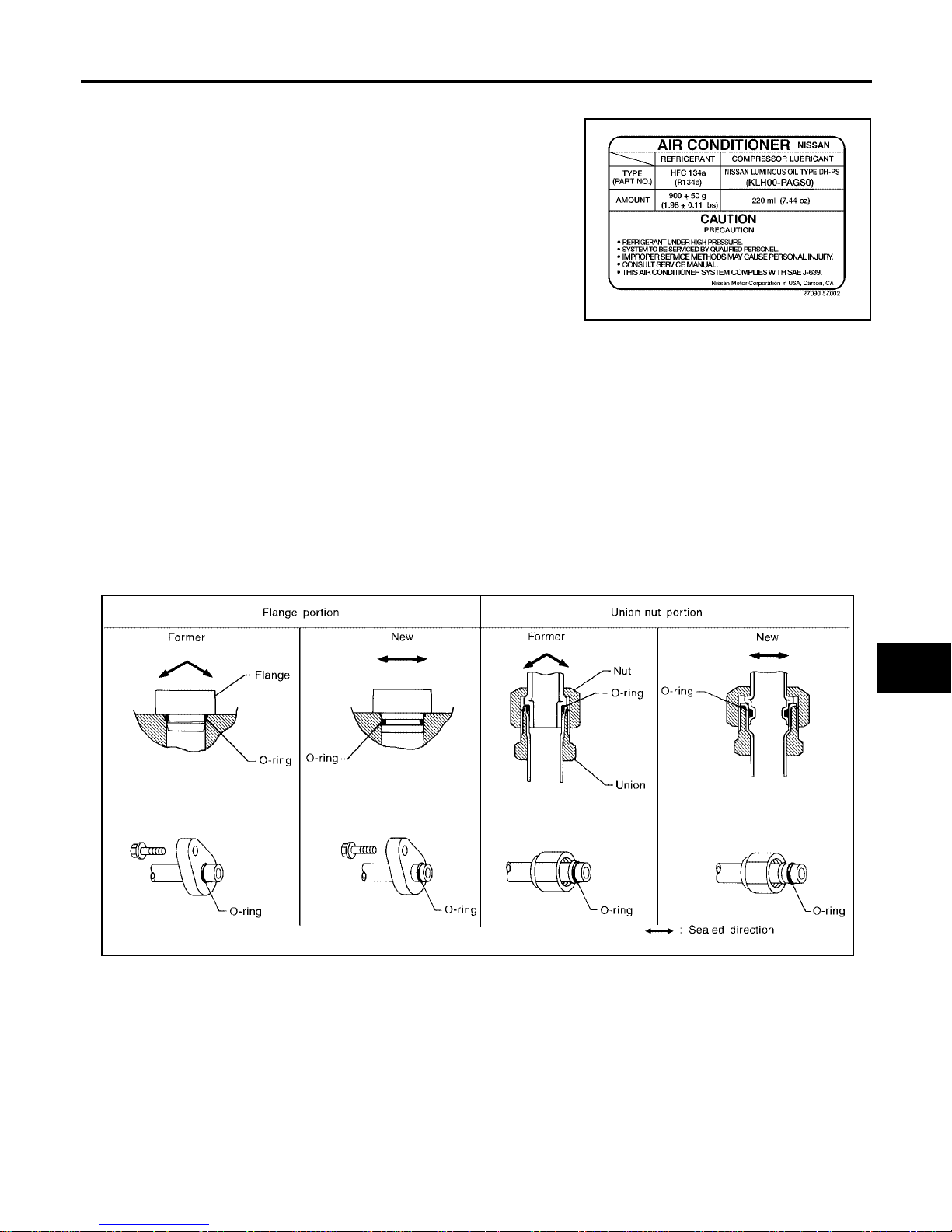
A new type refrigerant connection has been introduced to all refrigerant lines except the following locations.
● Expansion valve to co oling unit
● Evaporator pipes to evapora tor (inside cooling unit)
● Refrigerant pressure sensor
FEATURES OF NEW TYPE REFRIGERANT CONNECTION
● The O-ring has been relocated. It has also been provided with a groove for proper installation. This
reduces the po ssibil ity o f th e O-ring b eing caug ht in , or da maged by, the mating par t. Th e seal ing direct ion
of the O-ring is now se t vert ic al ly in re la tio n to th e co nt a ct in g su rf ace of th e mat ing p a rt t o im pro ve seal i ng
characteristics.
● The reaction force of the O-ring will not occur in the direction that causes the joint to pull out, thereby facil-
itating piping connections.
WJIA1232E
SHA815E
Page 8
MTC-8
PRECAUTIONS
Revision: January 2005 2004 Quest
O-RING AND REFRIGERANT CONNECTION
WJIA0370E
Page 9
PRECAUTIONS
MTC-9
C
D
E
F
G
H
I
K
L
M
A
B
MTC
Revision: January 2005 2004 Quest
CAUTION:
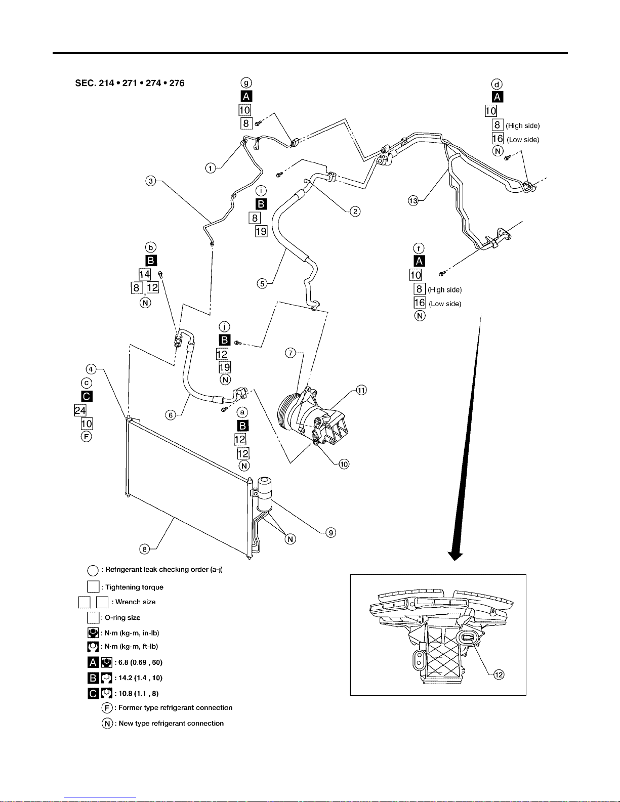
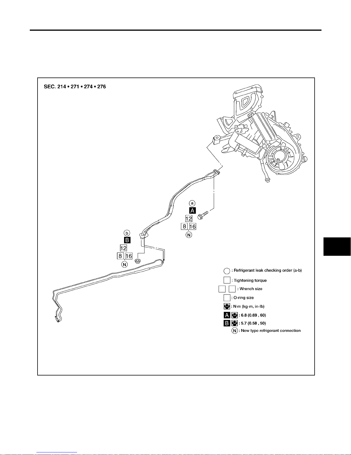
The new and former refrigeran t connections use different O-ring configuratio ns. Do not confuse Orings since they are not interchangeable. If a wrong O-ring is installed, refrigerant will leak at or
around the connection.
1. High-pressure service valve 2. Low-pressure service valve 3. High-pressure pipe
4. Refrigerant pressure sensor 5. Low-pressure flexible hose 6. High-pressure flexible hose
7. Shaft seal 8. Condenser 9. Liquid tank
10. Pressure relief valve 11. Compressor 12. Evaporator
13. High/low pressure pipe
LJIA0016E
Page 10
MTC-10
PRECAUTIONS
Revision: January 2005 2004 Quest
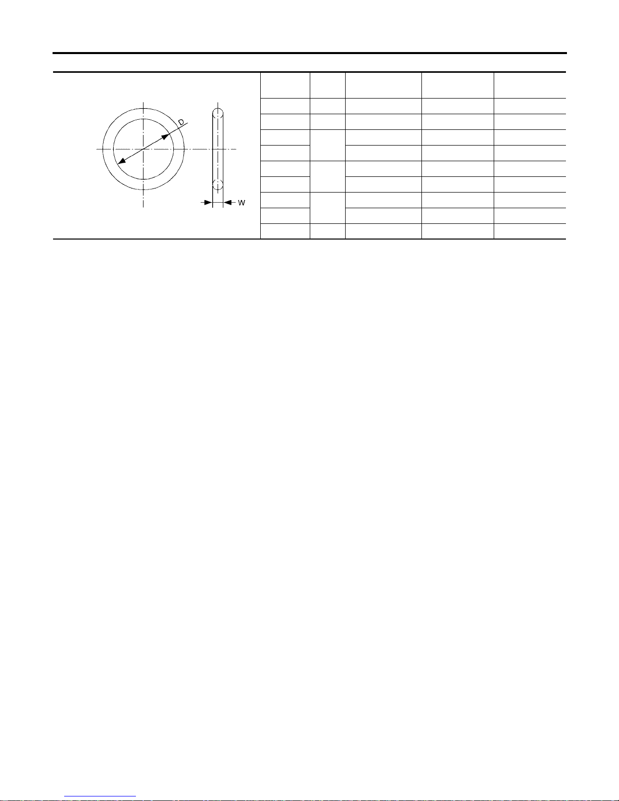
O-Ring Part Numbers and Specifications
*: Always check with the Parts Department for the latest parts information.
WARNING:
Make sure all refrigera nt is disc ha rg ed into the rec yc ling equi pm ent a nd the pr es su re in the sy ste m is
less than atmospheric pressure. Then gradually loosen the discharge side hose fitting and remove it.
CAUTION:
When replacing or cleanin g refrigerant cycle components, observe the following.
● When the compressor is remo ved, store it in the sa me positio n as it is whe n mounted on the car.
Failure to do so will cause lubricant to enter the low pressure chamber.
● When connecting tubes, always use a torque wrench and a back-up wrench.
● After disconnecting tubes, immediately plug all openings to prevent entr y of dirt and mo isture.
● When installing an air conditioner in the vehicle, c onne ct the pipes as the final stage of the opera-
tion. Do not remove the seal ca ps of pipes and other components until just before required for
connection.
● Allow components stored in cool areas to warm to working area temperature before removing seal
caps. This prevents condensation from forming inside A/C components.
● Thoroughly remove moisture from the refrigeration system before charging the refrigerant.
● Always replace used O-rings.
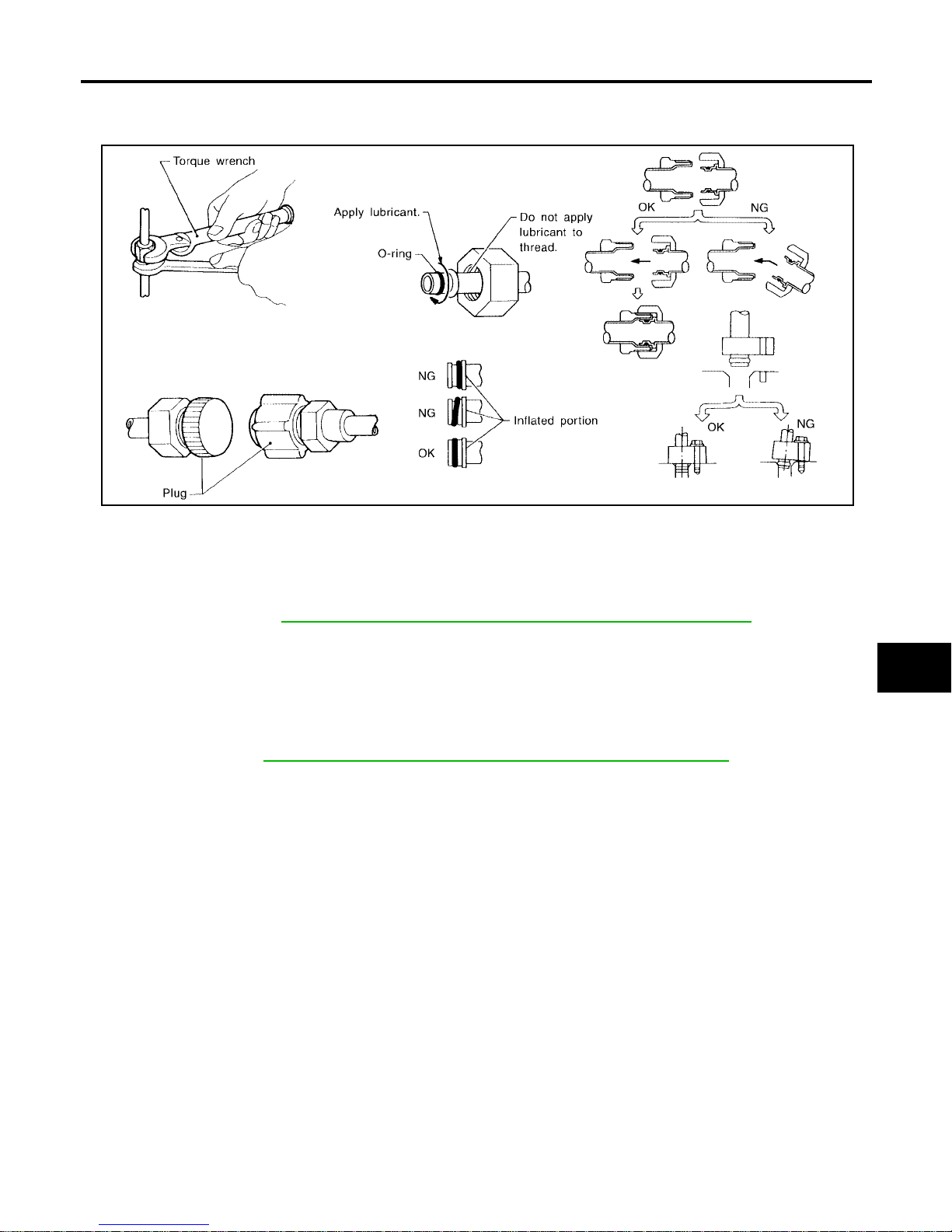
● When connecting tube, apply lubricant to circle of the O-rings shown in illustration. Be careful not
to apply lubricant to threaded portion.
● O-ring must be closely attached to dented portion of tube.
● When replacing the O-ring, be careful not to damage O-ring and tube.
● Connect tube until you hear it click, then tighten the nut or bolt by hand until snug. Make sure that
the O-ring is installed to tube correctly.
Connection type
O-ring
size
Part number* D mm (in) W mm (in)
New 8 92471 N8210 6.8 (0.268) 1.85 (0.0728)
Former 10 J2476 89956 9.25 (0.3642) 1.78 (0.0701)
New
12
92472 N8210 10.9 (0.429) 2.43 (0.0957)
Former 92475 71L00 11.0 (0.433) 2.4 (0.094)
New
16
92473 N8210 13.6 (0.535) 2.43 (0.0957)
Former 92475 72L00 14.3 (0.563) 2.3 (0.091)
New
19
92474 N8210 16.5 (0.650) 2.43 (0.0957)
Former 92477 N8200 17.12 (0.6740) 1.78 (0.0701)
New 24 92195 AH300 21.8 (0.858) 2.4 (0.094)
SHA814E
Page 11
PRECAUTIONS
MTC-11
C
D
E
F
G
H
I
K
L
M
A
B
MTC
Revision: January 2005 2004 Quest
● After connecting li ne, co nduct leak test and ma ke s ure that there is no lea kage from c onnections.
When the gas leaking point is found, disconnect that line and replace the O-ring. Then tighten connections of seal seat to the specified torque.
Precautions for Servicing Compressor EJS001RR
● Plug all openings to prevent moisture and foreign matter from entering.
● When the compressor is removed, store it in the same position as it is when mounted on the car.
● When replacing or repairing com pressor, follow “Maintenance of Lubrica nt Quantity in Com pres-
sor” exactly. Refer to MTC-22, "
Maintenance of Lubricant Quantity in Compressor" .
● Keep friction surfac es between clutch an d pulley clean. If the s urface is contaminated with lu bri-
cant, wipe it off by using a clean waste cloth moistened with thinner.
● After compressor service operation, turn the compressor shaft by hand more than 5 turns in both
directions. This will e qually distribute lubricant inside the compresso r. After the compresso r is
installed, let the engine idle and operate the compressor for 1 hour.
● After replac ing the compre ssor magnet clutch, apply voltage to the new one and check for normal
operation. Refer to MTC-149, "
Removal and Installation for Compressor Clutch"
Precautions for Service Equipment EJS001RS
RECOVERY/ RECYCLING EQUIPMENT
Follow the man uf ac turer's instructio ns for machine op era tion and machi ne m ai nte na nc e . N e ve r i ntroduce any
refrigerant other than that specified into the machine.
ELECTRONIC LEAK DETECTOR
Follow the manufacturer's instructions for tester operation and tester maintenance.
RHA861F
Page 12
MTC-12
PRECAUTIONS
Revision: January 2005 2004 Quest
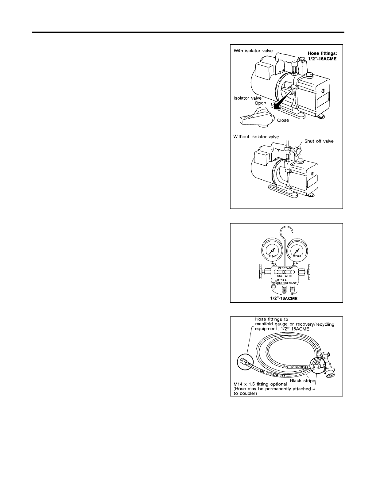
VACUUM PUMP
The lubricant contained inside the vac uum pump is not co mpatible
with the specified lubricant for HFC-134a (R-134a) A/C systems.
The vent side of the vacuum pump is exposed to atmospheric pressure so the vacuu m pump l ubric ant ma y migra te ou t of th e pump in to
the service hose. This is possible when the pump is switched off
after evacuation (vacuuming) and hose is connected to it.
To prevent this migration, use a manual valve situated near the
hose-to-pump connection, as follows.
● Usually vacuum pumps have a manual isolator valve as part of
the pump. Close this valve to isolate the service hose from the
pump.
● For pumps without an isolator, use a hose equipped with a man-
ual shut-off valve near th e pump end. Clo se the valv e to isolate
the hose from the pump.
● If the hose has an automatic shut off valve, disconnect the hose
from the pump: as long as the hose is connected, the valve is
open and lubricating oil may migrate.
Some one-way valves open when vacuum is applied and close
under a no vacuum co ndition. Such valves ma y restrict the pump's
ability to pull a deep vacuum and are not recom mended.
MANIFOLD GAUGE SET
Be certain that the gauge face indicates HFC-134a (R-134a) Make
sure the gauge set h as 1/2″-16 ACME threaded connections for service hoses. Confirm the set has been used only with refrigerant
HFC-134a (R-134a) along with specified lubricant.
SERVICE HOSES
Be certain that the service hoses display the markings described
(colored hose with black stripe). All hoses must include positive shutoff devices (either manual or automatic) near the end of the hoses
opposite the manifold gauge .
RHA270D
SHA533D
RHA272D
Page 13
PRECAUTIONS
MTC-13
C
D
E
F
G
H
I
K
L
M
A
B
MTC
Revision: January 2005 2004 Quest
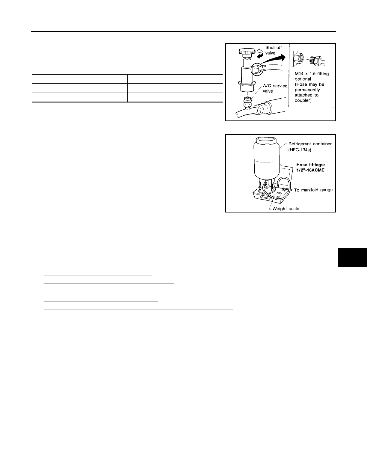
SERVICE COUPLERS
Never attempt to conn ect HFC-134a (R-1 34a) service coupl ers to a
CFC-12 (R-12) A/C system. The HFC-134a (R-134a) couplers will
not properly connect to the CFC-12 (R-12) system. If an improper
connection is attempted, discharging and contamination may occur.
REFRIGERANT WEIGHT SCALE
Verify that no refrigerant other than HFC134a (R-134a) and specified
lubricants have been used with the scale. If the scale controls refrigerant flow electronically, the hose fitting must be 1/2”-16 ACME.
CHARGING CYLINDER
Using a charging cylinder is not recommended. Refrigerant may be vented into air from cylinder's top valve
when filling the cylinder with refrigerant. Also, the accuracy of the cylinder is generally less than that of an
electronic sc ale or of quality recycle/recharge equipment.
Wiring Diagrams and Trouble Diagnosis EJS001RT
When you read wiring diagrams, refer to the following:
● GI-12, "How to Read Wiring Diagrams".
● PG-4, "POWER SUPPLY ROUTING CIRCUIT".
When you perform trouble diagnosis, refer to the following:
● GI-9, "How to Follow Trouble Diagnoses".
● GI-25, "How to Perform Efficient Diagnosis for an Electrical Incident".
Shut-off valve rotation A/C service valve
Clockwise Open
Counterclockwise Close
RHA273D
RHA274D
Page 14

MTC-14
PREPARATION
Revision: January 2005 2004 Quest
PREPARATION PFP:00002
Special Service Tools EJS001RU
The actual shapes of Kent-Moore tools may differ from those of special service tools illustrated here.
HFC-134a (R-134a) Service Tools and Equipment EJS001RV
Never mix HFC-134a refrigerant and/or its specified lubricant with CFC-12 (R-12) refrigerant and/or its lubricant.
Separate and non-interchangeable service equipment must be used for handling each type of refrigerant/lubricant.
Refrigerant containe r fittings, service hose fitti ngs and service equipment fit tings (equipment which handle s
refrigerant and/or lubricant) are differ ent between CFC-12 (R-12) and HFC-134a (R-134a). This is to avoid
mixed use of the refrigerants/lubricant.
Adapters that convert one size fitting to another must never be used refrigerant/lubricant contamination will
occur and compress or fai lure will result.
Tool number
(Kent-Moore No.)
Tool name
Description
KV99234330
(J-38873A)
Pulley installer
Installing pulley
KV99233130
(J-29884)
Pulley puller
Removing pulley
LHA171
LHA172
Tool number
(Kent-Moore No.)
Tool name
Description
HFC-134a (R-134a)
(—)
Refrigerant
Container color: Light blue
Container marking: HFC-134a (R134a)
Fitting size: Thread size
● large container 1/2"-16 ACME
KLH00-PAGS0
(—)
NISSAN A/C System Oil Type DHPS
Type: Poly alkylene glycol oil (PAG),
type DH-PS
Application: HFC-134a (R-134a) vane
rotary compresso rs (NISSAN only)
Lubricity: 40 m (1.4 US fl oz, 1.4 Imp
fl oz)
—
(ACR2005-NI)
ACR5 A/C Service Center
Refrigerant recovery and recycling and
recharging
S-NT196
S-NT197
WJIA0293E
Page 15
PREPARATION
MTC-15
C
D
E
F
G
H
I
K
L
M
A
B
MTC
Revision: January 2005 2004 Quest
—
(J-41995)
Electronic refrigerant leak detector
Checking for refrigerant leaks
(Power supply: DC 12V (Cigarette
lighter)
—
(J-43926)
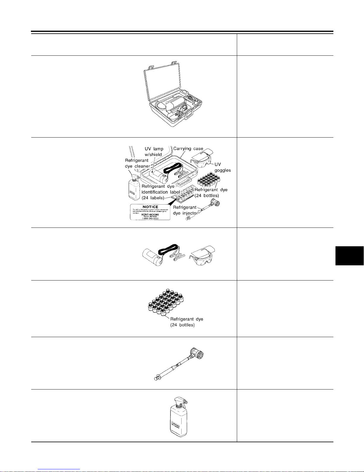
Refrigerant dye leak detection kit
Kit includes:
(J-42220)
UV lamp and UV safety goggles
(J-41459)
Refrigerant dye injector
(J-41447)
Quantity 24, 1/4 ounce bottles of
HFC-134a (R-134a) fluorescent
leak detection dye
(J-43872)
Refrigerant dye cleaner
Leak detection dye
(Power supply: DC 12V battery terminal)
—
(J-42220)
Fluorescent dye leak detector
Checking for refrigerant leaks when fluorescent dye is installed in A/C system.
Includes: UV lamp and UV safety goggles
(Power supply: DC 12V battery terminal)
—
(J-41447)
HFC-134a (R-134a) fluorescent
leak detection dye
(Box of 24, 1/4 ounce bottles)
Application: For HFC-134a (R-134a)
PAG oil
Container: 1/4 ounce (7.4cc) bottle
(Includes self-adhesive dye identification labels for affixing to vehicle after
charging system with dye.)
—
(J-41459)
HFC-134a (R-134a) Dye injector
Use with (J-41447) 1/4 ounce bottles
For injecting 1/4 ounce of fluorescent
leak detection dye into A/C system.
—
(J-43872)
Refrigerant dye cleaner
For cleaning dye spills.
Tool number
(Kent-Moore No.)
Tool name
Description
AHA281A
ZHA200H
SHA438F
SHA439F
SHA440F
SHA441F
Page 16
MTC-16
PREPARATION
Revision: January 2005 2004 Quest
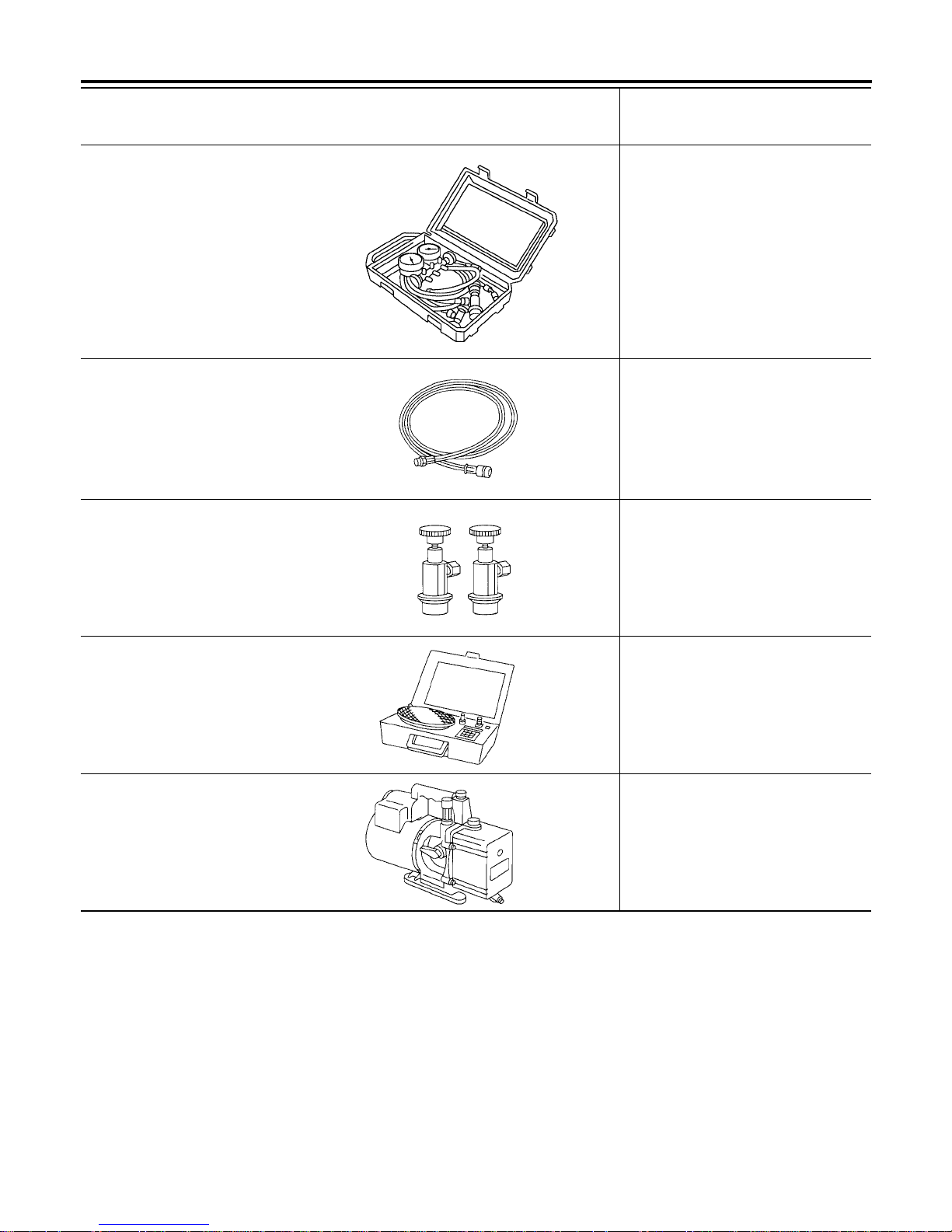
Commercial Service Tools EJS001RW
—
(J-39183-C)
Manifold gauge set (with hoses
and couplers)
Identification:
● The gauge face indicates R-134a.
Fitting size: Thread size
● 1/2"-16 ACME
Service hoses:
● (J-39500-72B)
High side hose
● (J-39500-72R)
Low side hose
● (J-39500-72Y)
Utility hose
Hose colors:
● Low side hose: Blue with black stripe
● High side hose: Red with black stripe
● Utility hose: Yellow with black stripe
or green with black stripe
Hose fitting to gauge:
● 1/2"-16 ACME
Service couplers:
● (J-39500-20A)
High side coupler
● (J-39500-24A)
Low side coupler
Hose fitting to service hose:
● M14 x 1.5 fitting is optional or perma-
nently attached.
—
(J-39699)
Refrigerant weight scale
For measuring of refrigerant
Fitting size - thread size:
● 1/2" - 16 ACME
—
(J-39649)
Vacuum pump
(Including the isolator valve)
Capacity:
● Air displacement: 4 CFM
● Micron rating: 20 microns
● Oil capacity: 482 g (17 oz)
Fitting size: Thread size
● 1/2"-16 ACME
Tool number
(Kent-Moore No.)
Tool name
Description
RJIA0196E
S-NT201
S-NT202
S-NT200
S-NT203
Page 17
PREPARATION
MTC-17
C
D
E
F
G
H
I
K
L
M
A
B
MTC
Revision: January 2005 2004 Quest
Tool number
Tool name
Description
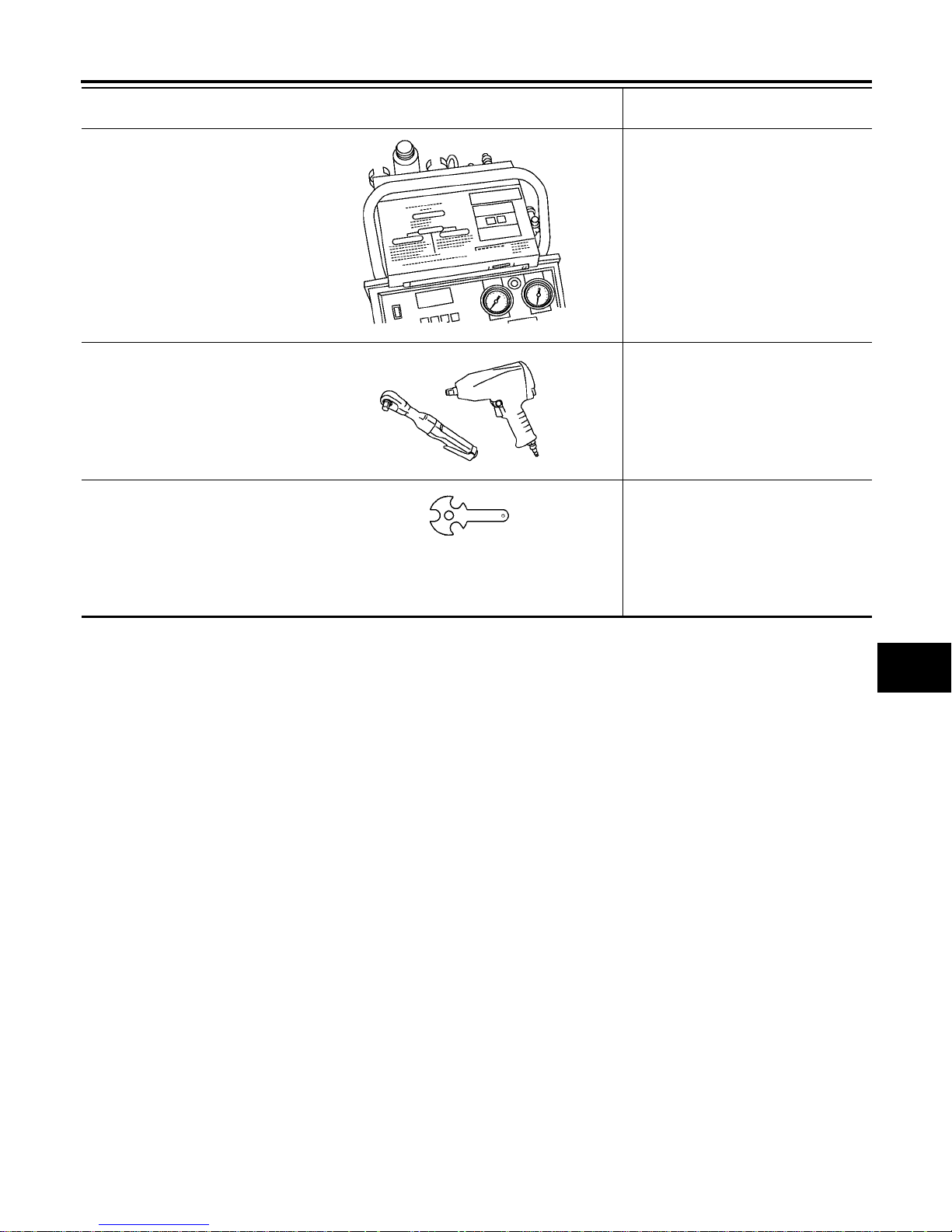
(J-41810-NI)
Refrigerant identifier equipment (R134a)
For checking refrigerant purity and
system contamination
Power tool Loosening bolts and nuts
(J-44614)
Clutch disc holding tool
Clutch disc holding tool
RJIA0197E
PBIC0190E
WHA230
Page 18

MTC-18
REFRIGERATION SYSTEM
Revision: January 2005 2004 Quest
REFRIGERATION SYSTEM PFP:KA990
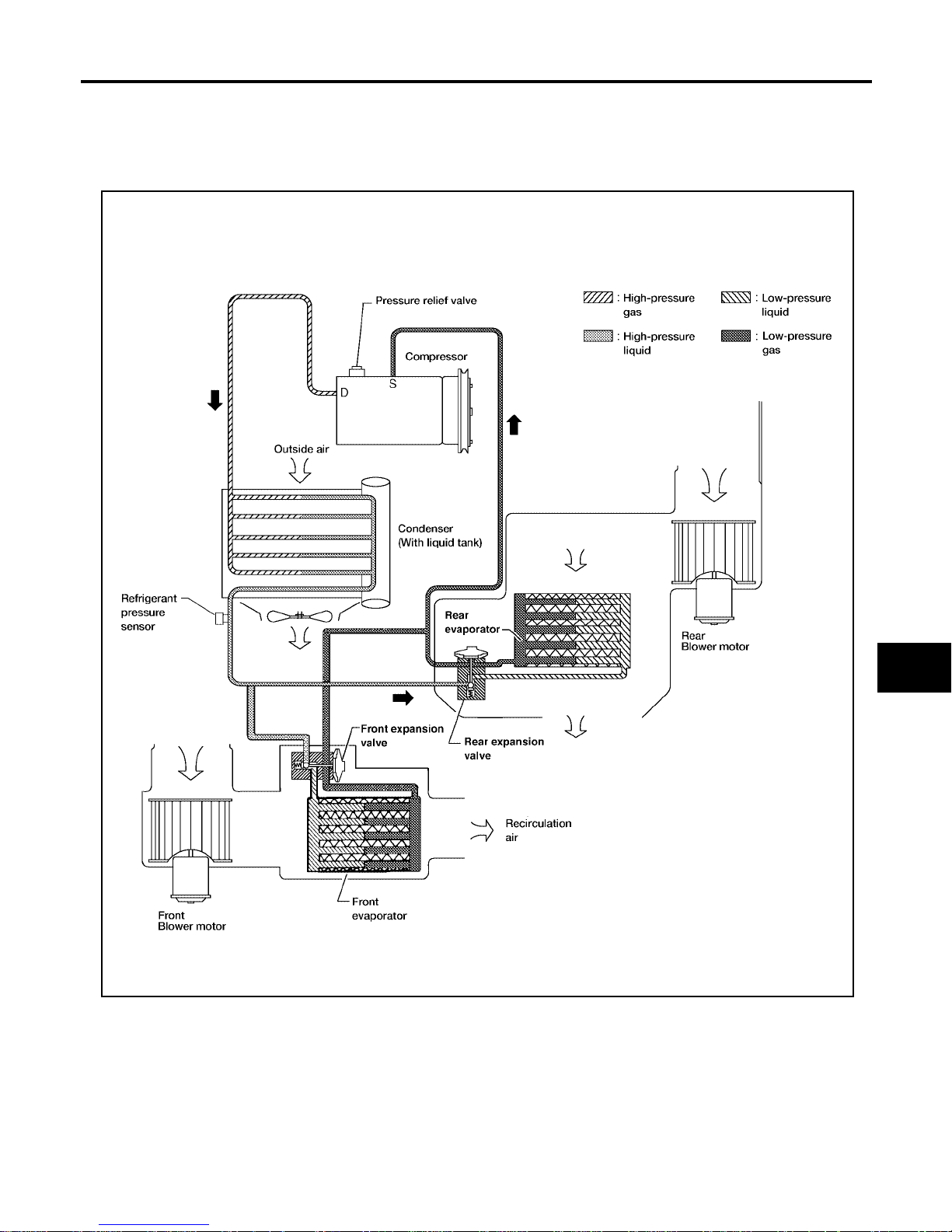
Refrigerant Cycle EJS001RX
REFRIGERANT FLOW
The refrigerant flows in the standard pattern, that is, through the compressor, the condenser with liquid tank,
through the front and resar evaporators, and back to the compressor. The refrigerant evaporation through the
evaporator coils are controlled by a fr ont and rear externally e qualized expansion v alves, located inside t he
front and rear evaporator cases.
Refrigerant System Protect ion EJS001RY
REFRIGERANT PRESSURE SENSOR
The refrigerant system is protected against excessively high or low pressures by the refrigerant pressure sensor , l oc at ed on t he co nd enser. If the syste m p ress ur e r is es ab ov e or fa lls be lo w t he sp eci fic at i on s, t he ref r ige rant pressure sensor detects the pressure inside the refrigerant line and sends a voltage signal to the ECM.
The ECM deenergizes the A/C relay to disengage the magnetic compressor clutch when pressure on the high
pressure side detected by refri gerant pressure sensor is over about 2,746 kPa (28 kg /cm
2
, 398 psi), or below
about 120 kPa ( 1 .22 kg/cm
2
, 17.4 psi).
Page 19
REFRIGERATION SYSTEM
MTC-19
C
D
E
F
G
H
I
K
L
M
A
B
MTC
Revision: January 2005 2004 Quest
PRESSURE RELIEF VALVE
The refrige rant system i s also protected by a pr essure relief valve, loc ated in the rear head of the compressor.
When the pressure of refrigerant in the system increases to an abnormal level [more than 2,990 kPa (30.5 kg/
cm
2
, 433.6 psi)], the release p ort on the pressure relief valv e automatically open s and releases refrigerant
into the atmosphere.
WJIA1342E
Page 20
MTC-20
REFRIGERATION SYSTEM
Revision: January 2005 2004 Quest
Component Layout EJS001RZ
FRONT REFRIGERATION SYSTEM
LJIA0085E
Page 21

REFRIGERATION SYSTEM
MTC-21
C
D
E
F
G
H
I
K
L
M
A
B
MTC
Revision: January 2005 2004 Quest
REAR REFRIGERATION SYSTEM
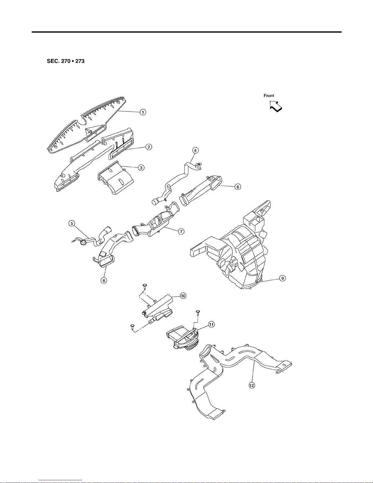
1. Defroster nozzle 2. Fresh air duct 3. Defroster duct
4. RH side demister duct 5. LH side demister duct 6. RH ventilator duct
7. Center ventilator duct 8. LH ventilator duct 9. Front heater and cooling unit assembly
10. Floor connector duct 11. Floor distribution duct 12. Floor duct
1. Rear overhead duct 2. Rear heat duct 3. Rear heater and cooling unit assembly
4. Clips
LJIA0086E
Page 22
MTC-22
LUBRICANT
Revision: January 2005 2004 Quest
LUBRICANT PFP:KLG00
Maintenance of Lubricant Quantity in Compressor EJS001S0
The lubricant in the c ompressor circulates thro ugh the syst em with the refrig erant. Add lubr icant to compre ssor when repl ac in g an y c omp on en t or a f te r a la rge r e fri ge ran t le ak ag e h as occu r red . It is im po rtant to maintain
the specified amount.
If lubricant quantity is not maintained properly, the following malfunctions may result:
● Lack of lubricant: May le ad to a seized compressor
● Excessive lubricant: Inadequate cooling (thermal exchange interference)
LUBRICANT
Name: Nissan A/C System Lubricant Type (DH-PS)
Part number: KLH00-PAGS0
CHECKING AND ADJUSTING
CAUTION:
If excessive lubricant leakage is noted, do not perform the lubricant return operation.
Start the engine and set the following conditions:
test condition
● Engine speed: Idling to 1,200 rpm
● A/C switch: On
● Blower speed: Max. position
● Temp. con trol: Op tiona l [Set so that intake air temperat ure is 25° to 30° C (77° to 86°F).]
● Intake position: Recirculation ( )
● Perform lubricant return operation for about ten minutes
Adjust the lubricant quantity according to the following table.
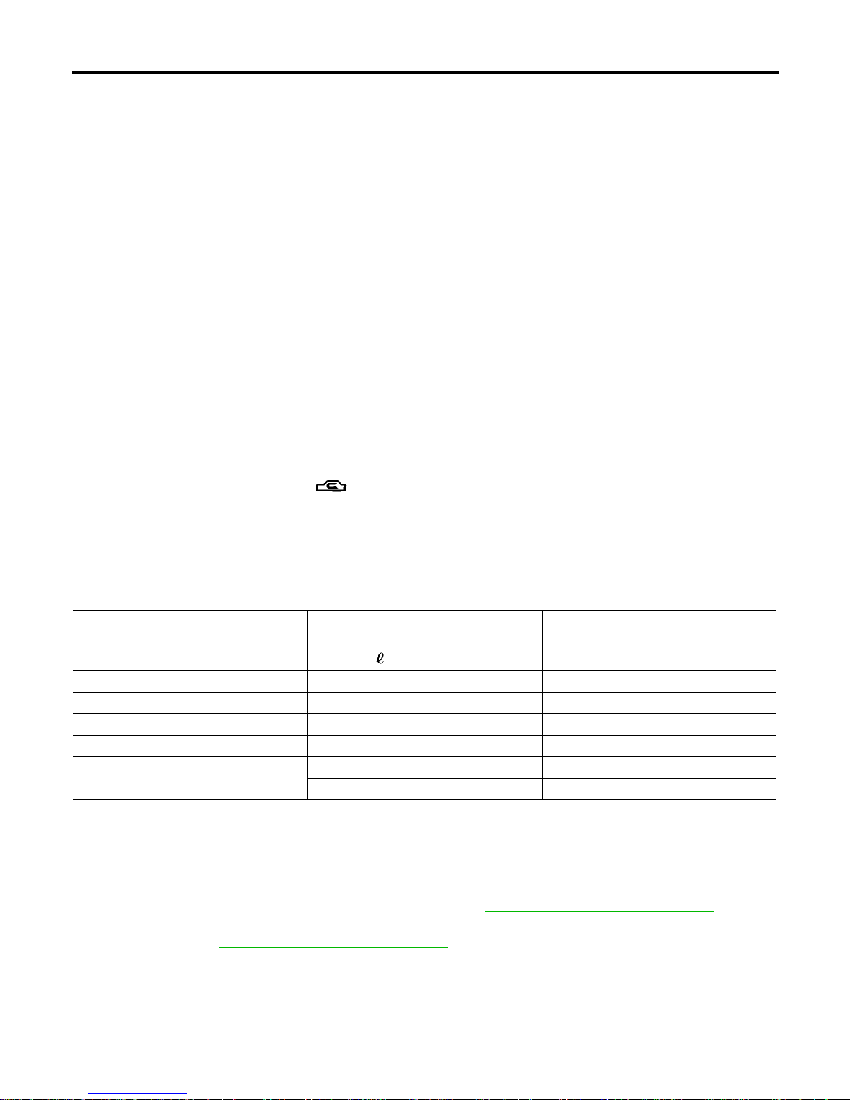
Lubricant Adjusting Procedure for Components Replacement Except Compressor
After replacing any of the following major components, add the correct amount of lubricant to the system.
Amount of Lubricant to be Added
*1: If refrigerant leak is small, no addition of lubricant is needed.
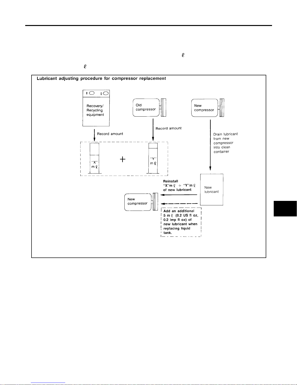
Lubricant Adjustment Procedure for Compressor Replacement
1. Before connecting recovery/recycling equipment to vehicle, check recovery/recycling equipment gauges.
No refrigerant pressure should be displayed. If NG, recover refrigerant from equipment lines.
2. Connect recovery/recycling equipment to vehicle. C onfirm refrigerant purity in supply tank using recovery/
recycling equipment and refrigerant identifier. If NG, refer to MTC - 5, "
Contaminated Refrigerant" .
3. Confirm refrigerant purity in vehicle A/C system using recovery/recycling equipment and refrigerant identifier. If NG, refer to MTC-5, "
Contaminated Refrigerant" .
4. Discharge refr ig era nt in to th e rec ov ery /re cy c lin g eq ui pm en t. Me as ure lub ric an t dis c ha rged into the recovery/recycling equip m en t.
5. Drain the lubricant from the “old” (removed) compressor into a graduated container and recover the
amount of lubricant drained.
6. Drain the lubricant from the “new” compressor into a separate, clean container.
Part replaced
Lubricant to be added to system
Remarks
Amount of lubricant
m (US fl oz, Imp fl oz)
Front evaporator 75 (2.5, 2.6) —
Rear evaporator 75 (2.5, 2.6) —
Condenser 75 (2.5, 2.6) —
Liquid tank 5 (0.2, 0.2) Add if compressor is not replaced.
In case of refrigerant leak
30 (1.0, 1.1) Large leak
— Small leak *1
Page 23
LUBRICANT
MTC-23
C
D
E
F
G
H
I
K
L
M
A
B
MTC
Revision: January 2005 2004 Quest
7. Measure an amount of new lubricant installed equal to amount drained from “old” compressor. Add this
lubricant to “new” comp re ss or thro ug h the suct io n po rt ope ni ng .
8. Measure an amount o f n ew l ub ric an t eq ua l to t h e a mou nt r e cover e d d uri ng di sc har gi ng. A d d thi s l u bri can t
to “new” compressor through the suction port opening.
9. If the liquid tank also needs to be replaced, add an additional 5 m (0.2 US fl oz, 0.2 Imp fl oz) of lubricant
at this time.
Do not add this 5 m (0.2 US fl oz, 0.2 Imp fl oz) of lubricant if only replacing the compressor.
RHA065DD
Page 24

MTC-24
AIR CONDITIONER CONTROL
Revision: January 2005 2004 Quest
AIR CONDITIONER CONTROL PFP:27500
Description EJS001UD
The front air control provides regulation of the vehicle's interior temperature. The system is based on the position of the front air controls temperature switch selected by the driver. This is done by utilizing a microcomputer, also referred to as the front air control, which receives input signals from the following three sensors:
● Ambient sensor
● Intake sensor
● PBR (Position Balanced Resistor).
The front air control uses th ese signals (including the set position of the temperature switch) to control:
● Outlet air volume
● Air temperature
● Air distribution
The front air control also provides separate regulation of the vehicle's interior temperature for the rear passenger area. The system is based on the temperature and rear blower settings selected from rear control
switches located on the front air control, or from the temperature and rear blower settings selected from rear
control switches on the rear air control, when the front air co ntrol switches are set to the rear position.
The front air control is used to select:
● Outlet air volume
● Air temperature/distribution
Operation EJS001S2
AIR MIX DOOR CONTROL
The air mix door is controlled so that in-vehicle temperature changed based on the position of the temperature
switch.
BLOWER SPEED CONTROL
Blower speed is controlled based on front and rear blower switch settings.
When blower swit ch is turned, the blower m otor starts and increases air flow v olume each time the blowe r
switch is turned clockwise, and de creases air flow volume each time th e blower switch is turned counterclockwise.
When engine coola nt tempe rature is low, the blower motor oper ation is de layed to prevent coo l air from f lowing.
INTAKE DOORS CONTROL
The intake doors are controlled by the recirculation switch setting, and the mode (defroster) switch setting.
MODE DOOR CONTROL
The mode door is controlled by the position of the mode switch.
DEFROSTER DOOR CONTROL
The defroster door is controlled by: Turning the defroster dial to front defroster.
Page 25
AIR CONDITIONER CONTROL
MTC-25
C
D
E
F
G
H
I
K
L
M
A
B
MTC
Revision: January 2005 2004 Quest
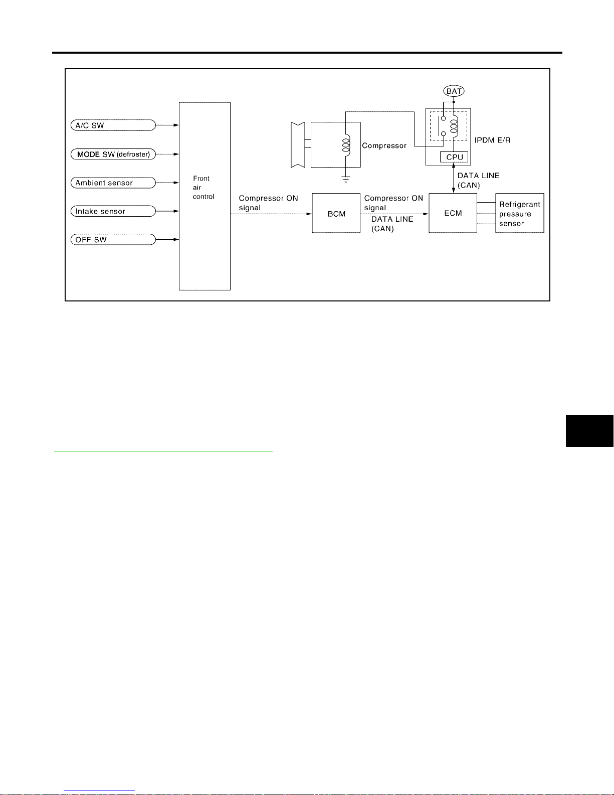
MAGNET CLUTCH CONTROL
When the A/C switch is pressed, or the mode switch is turned to the defroster position, the front air control outputs a compressor ON signal to BCM.
The BCM then sends a compressor ON signal to ECM, via CAN communication line.
ECM judges whether compressor can be turned ON, based on each sensor status (refrigerant pressure sensor signal, throttle an gle sensor, etc.). If it judges compres s or ca n b e turn ed ON , it sends compresso r ON si gnal to IPDM E/R, via CAN communication line.
Upon receipt of comp ressor ON signal from ECM, IPDM E/R turns air conditioner relay ON to operate compressor.
SELF-DIAGNOSTIC SYSTEM
The self-diagnosti c system is buil t into the front air control to qu ickly locate the cause of symptom s. Refer to
MTC-50, "
A/C System Self-diagnosis Function" .
WJIA1203E
Page 26
MTC-26
AIR CONDITIONER CONTROL
Revision: January 2005 2004 Quest
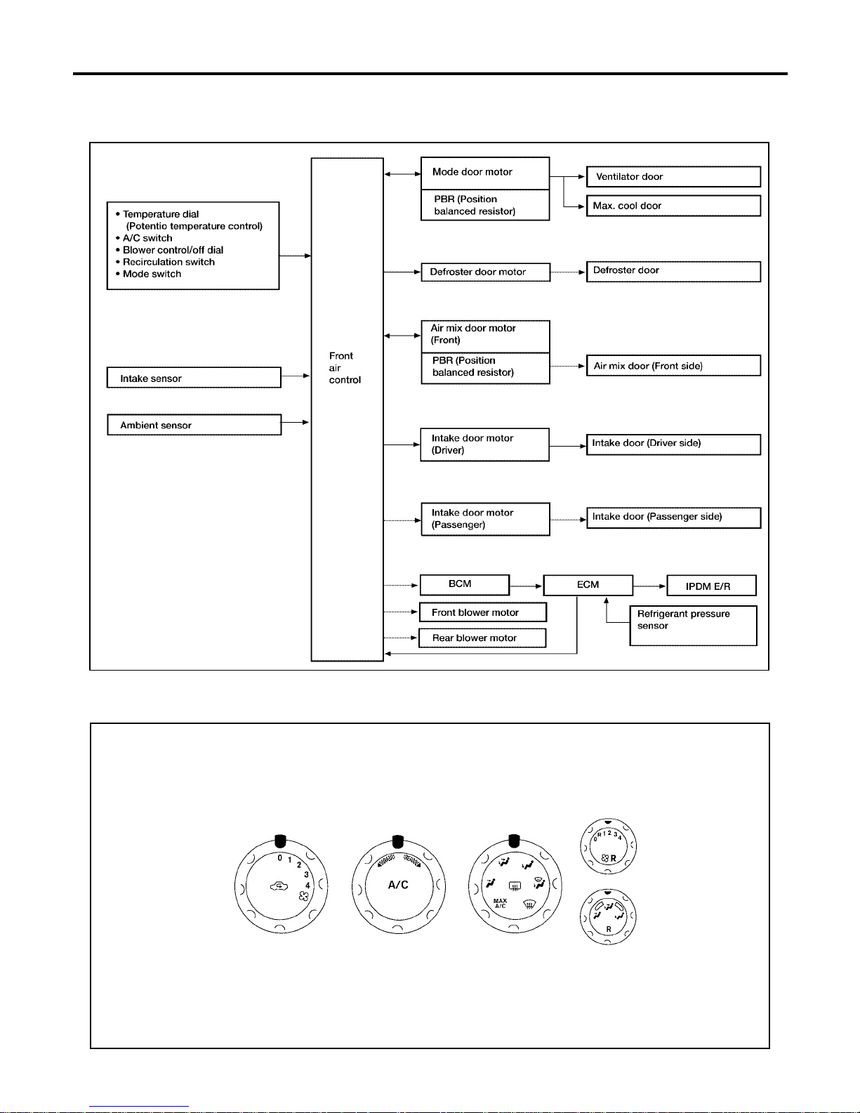
Description of Control Syste m EJS001S3
The control sy stem consists of input sensors, switches, the front air co ntrol (microcomputer) and outputs.
The relation ship of these components i s shown in the figure below:
Control Operation EJS001S4
Front air control
WJIA1610E
WJIA0485E
Page 27
AIR CONDITIONER CONTROL
MTC-27
C
D
E
F
G
H
I
K
L
M
A
B
MTC
Revision: January 2005 2004 Quest
Rear air control
DISPLAY SCREEN
Displays the operational status of the system.
TEMPERATURE DIAL (TEMPERATURE CONTROL) (FRONT)
Increases or decreases the set temperature.
TEMPERATURE DIAL (TEMPERATURE CONTROL) (REAR)
Increases or decreases the set temperature.
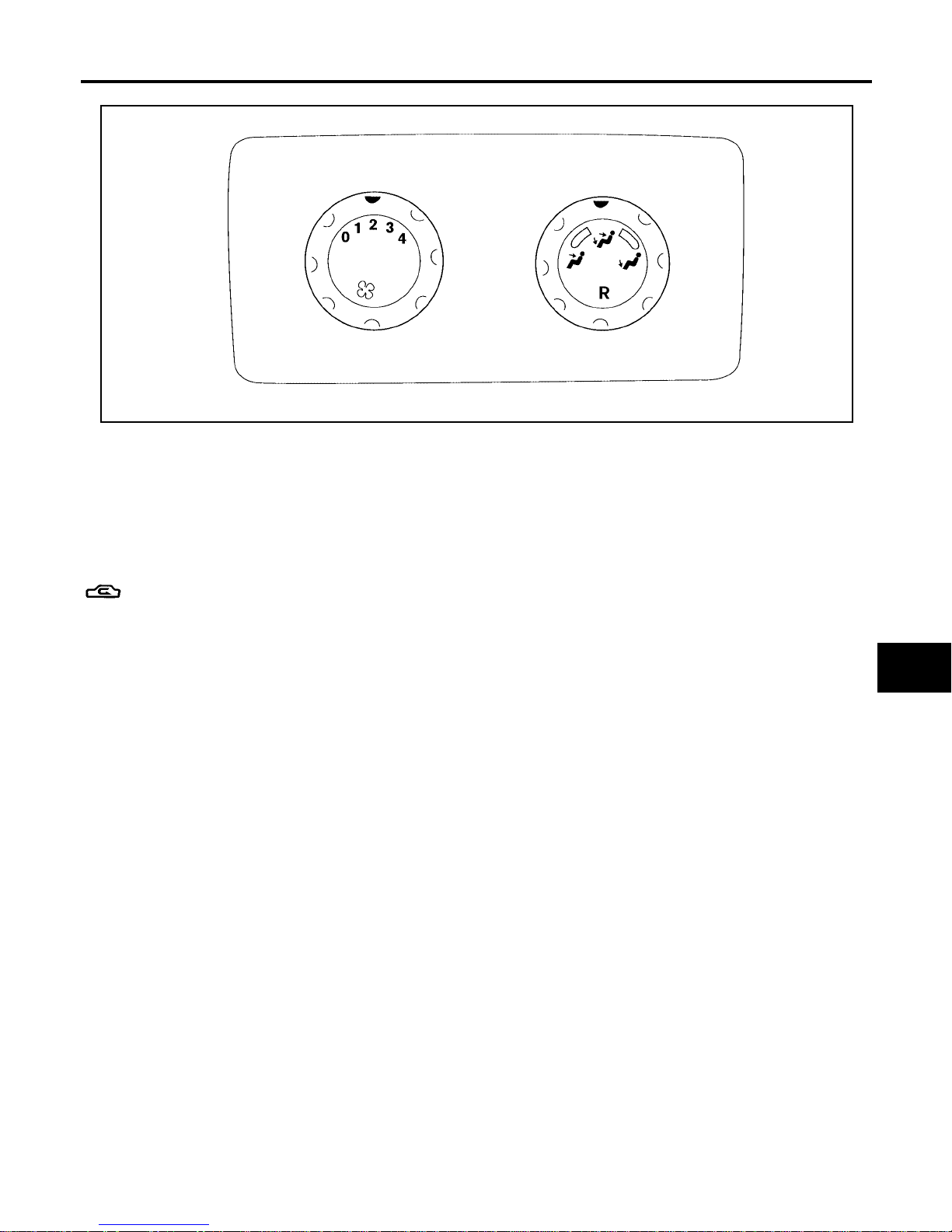
RECIRCULATION () SWITCH
● When REC switch is ON, REC switch indicator turns ON, and air inlet is set to REC.
● When REC switch is turned OFF, or when compressor is turned from ON to OFF, REC switch is automati-
cally turned OFF. REC mode can be re-entered by pressing REC switch again.
● REC switch is not operated when DEF switch is turned ON, or at the D/F position.
REAR WINDOW DEFOGGER SWITCH
When switch is ON, rear window is defogged.
OFF DIAL (BLOWER SPEED SET TO 0)
The compressor a nd blower are OFF, the intake doors are set to the outside air position, and t he air outlet
doors are set to the foot (75% foot and 25% defrost) position.
A/C SWITCH
The compressor is ON or OFF.
MODE DIAL
Controls the air discharge outlets thr ough control of the mode and defroster doors.
FRONT BLOWER CONTROL DIAL
Manually control the blower speed. Four speeds are available for manual control (as shown on the display
screen).
REAR BLOWER CONTROL DIAL
When the rear blower switch (front) is in the OFF position, the rear blower motor cannot operate.
When the rear blow er switch (front) is in the RE AR position, it al lows the rear b lower switch (re ar) to control
the rear blower motor speed. In any other position (1-4) , the rear blower switch (front) controls the rear blower
motor speed regardless of the rear blower swi tch (rear) posi tio n.
LJIA0024E
Page 28
MTC-28
AIR CONDITIONER CONTROL
Revision: January 2005 2004 Quest
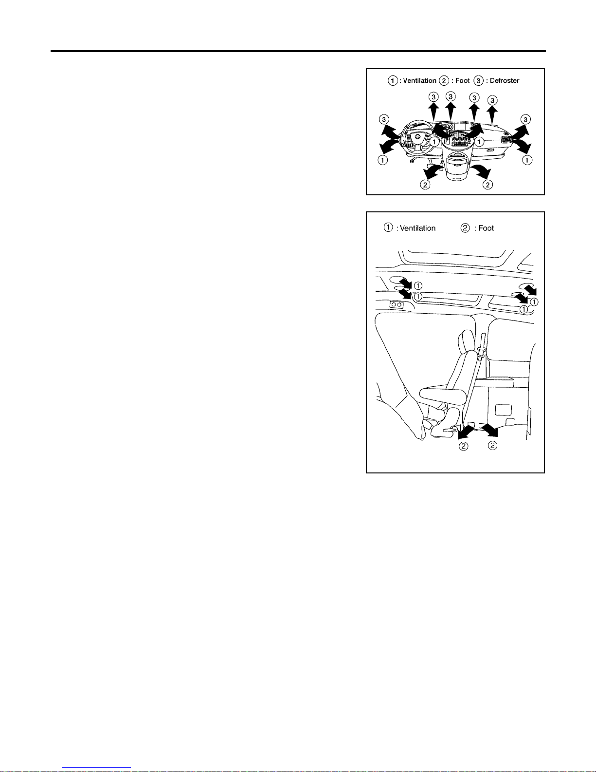
Discharge Air Flow EJS001S6
FRONT
REAR
WJIA1037E
LJIA0127E
Page 29
AIR CONDITIONER CONTROL
MTC-29
C
D
E
F
G
H
I
K
L
M
A
B
MTC
Revision: January 2005 2004 Quest
System Description EJS001S7
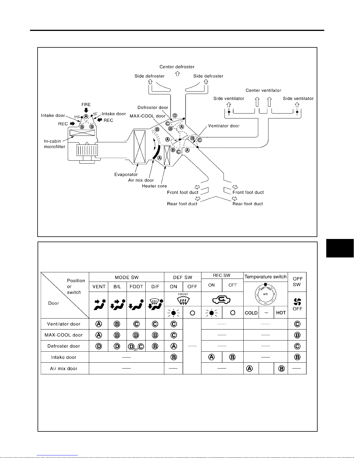
SWITCHES AND THEIR CONTROL FUNCTION
WJIA0531E
WJIA0532E
Page 30

MTC-30
AIR CONDITIONER CONTROL
Revision: January 2005 2004 Quest
CAN Communication System Description EJS001S8
Refer to LAN-6, "CAN COMMUNICATION" .
Page 31
TROUBLE DIAGNOSIS
MTC-31
C
D
E
F
G
H
I
K
L
M
A
B
MTC
Revision: January 2005 2004 Quest
TROUBLE DIAGNOSIS PFP:00004
CONSULT-II Function (BCM) EJS001S9
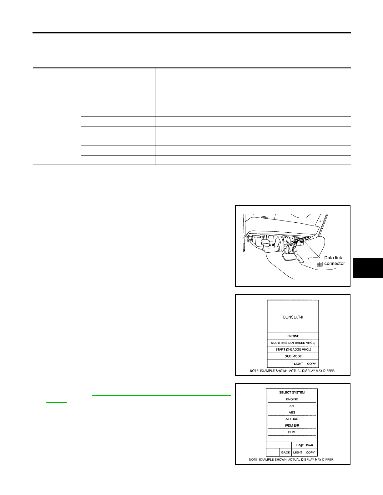
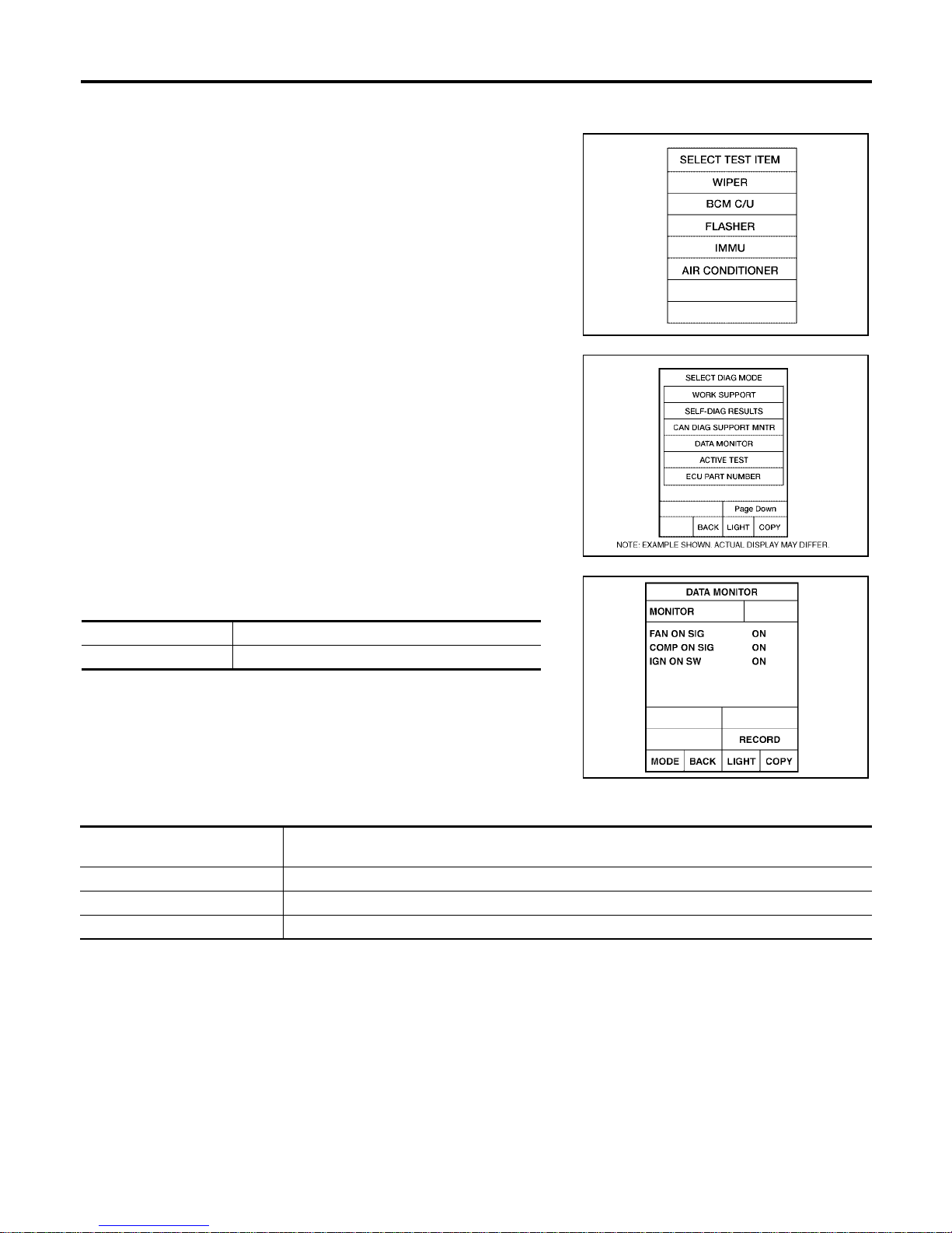
CONSULT-II can display each diag nostic item using the diagnost ic test modes show n following.
CONSULT-II BASIC OPERATION
CAUTION:
If CONSULT-II is used with no connection of CONSULT-II CONVERTER, malfunctions might be
detected in self-diagnosis depending on control unit which carries out CAN communication.
1. With the ignition switch OFF, connect CONSULT-II and CONSUL T-II converter to t he dat a li nk conn ecto r, and turn the ignition
switch ON.
2. To uc h “START (NISSAN BASED VHCL)”.
3. Touch “BCM” on “SELECT SYSTEM” screen. If “BCM” is not
indicated, go to GI-37, "
CONSULT-II Data Link Connector (DLC)
Circuit" .
BCM diagnostic
test item
Diagnostic mode Description
Inspection by part
WORK SUPPORT
Supports inspections and adjustments. Commands ar e transm i tted t o the BCM
for setting the status suitable for required operation, input/outp ut signals are
received from the BCM and received data is displayed.
DATA MONITOR Displays BCM input/output data in real time.
ACTIVE TEST Operation of electrical loads can be checked by sendi ng dr ive sig nal to them .
SELF-DIAG RESULTS Displays BCM self-diagnosis results.
CAN DIAG SUPPORT MNTR The result of transmit/receive diagnosis of CAN communication can be read.
ECU PART NUMBER BCM part number can be read.
CONFIGURATION Perfor m s BCM con figur at i on rea d/wri te functi ons.
BBIA0336E
BCIA0029E
BCIA0030E
Page 32
MTC-32
TROUBLE DIAGNOSIS
Revision: January 2005 2004 Quest
DATA MONITOR
Operation Procedure
1. Touch “AIR CONDITIONER” on “SELECT TEST ITEM” screen.
2. Touch “DATA MONITOR” on “SELECT DIAG MODE” screen.
3. Touch either “ALL SIGN ALS ” or “ SEL E CT ION FR OM MEN U” on
“DATA MONITOR” screen.
4. Touch “START”.
5. When “SELECTION FROM MENU” is selected, touch items to
be monitored. When “ALL SIGNALS” is selected, all the items
will be monitored.
6. Touch “RECORD” while monitoring, then the status of the monitored item can be recorded. To stop recording, to uch “STOP”.
Display Item List
WJIA0468E
BCIA0031E
All signals Monitors all the items.
Selection from menu Selects and monitors the individual item selected.
WJIA0469E
Monitor item name “operation or
unit”
Contents
IGN ON SW “ON/OFF” Displays “IGN Position (ON)/OFF, ACC Position (OFF)” status as judged from ignition switch signal.
COMP ON SIG “ON/OFF” Displays “COMP (ON)/CO MP ( OFF)” status as judged from ai r cond itioner sw itch signal.
FAN ON SIG “ON/OFF” Displays “FAN (ON)/FAN (OFF)” status as judged from blower fan motor switch signal.
Page 33
TROUBLE DIAGNOSIS
MTC-33
C
D
E
F
G
H
I
K
L
M
A
B
MTC
Revision: January 2005 2004 Quest
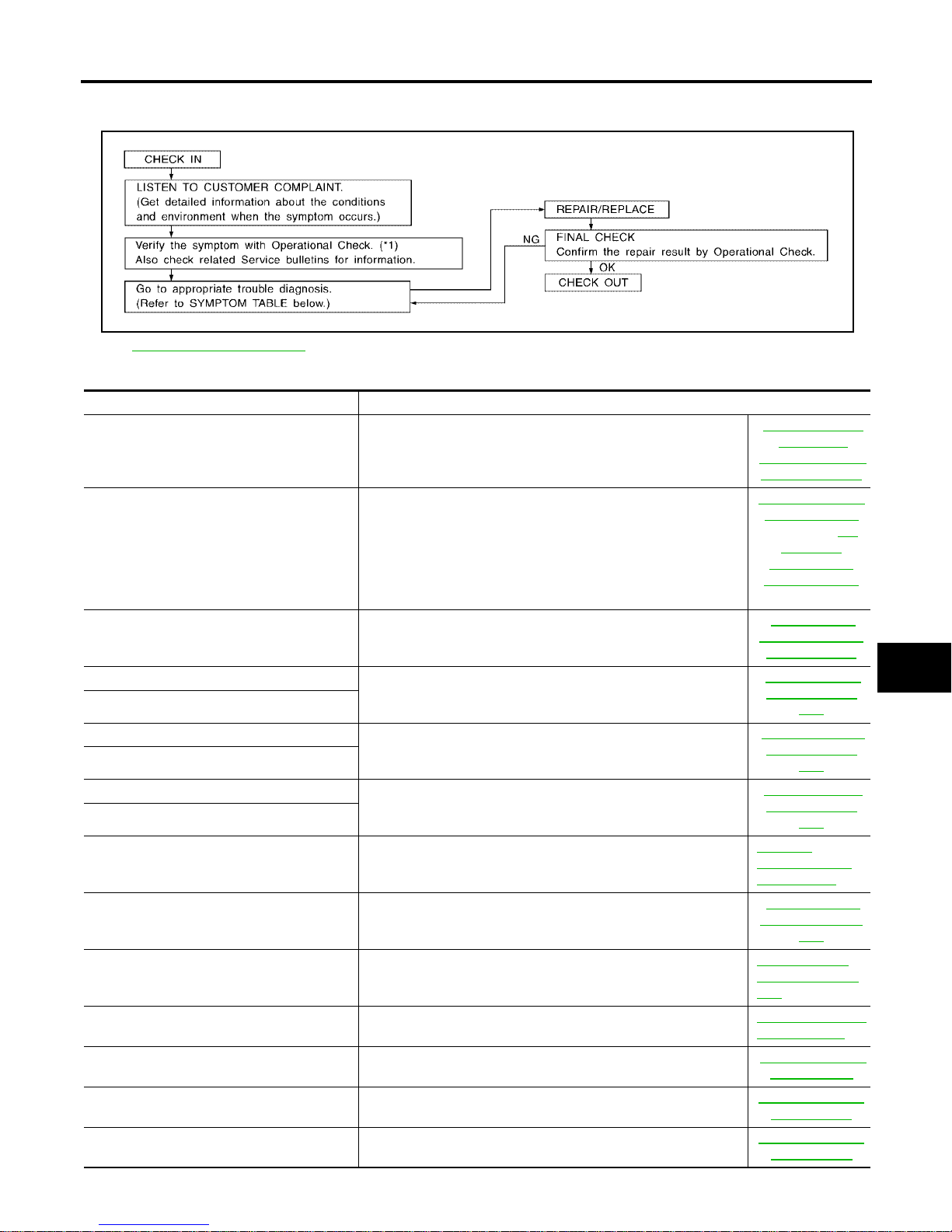
How to Perform Trouble Diagnosis for Quick and Accurate Repair EJS001SA
WORK FLOW
SYMPTOM TABLE
*1 MTC-52, "Operational Check"
SHA900E
Symptom Reference Page
A/C system does not come on. Go to Trouble Diagnosis Procedure for A/C System.
MTC-54, "
Power
Supply and
Ground Circuit for
Front Air Control"
A/C system display is malfunctioning. Go to "Navigation Syste m", or "Int egr ate d D isp lay Syst em ".
AV-118, "
NAVIGATION SYSTEM"
(With Navi.) AV-
89, "INTE-
GRATED DIS-
PLAY SYSTEM"
(Without Navi.)
A/C system cannot be controlled. Go to Self-diagnosis Function.
MTC-50, "
A/C
System Self-diag-
nosis Function"
Air outlet does not change.
Go to Trouble Diagnosis Procedure for Mode Door Motor.
MTC-57, "Mode
Door Motor Cir-
cuit"
Mode door motor is malfunctioning.
Discharge air temperature does not chang e.
Go to Trouble Diagnosis Procedure for Air Mix Door Motor.
MTC-61, "
Air Mix
Door Motor Cir-
cuit"
Air mix door motor is malfunctioning.
Intake door does not change.
Go to Trouble Diagnosis Procedure for Intake Door Motor.
MTC-67, "
Intake
Door Motor Cir-
cuit"
Intake door motor is malfunctioning.
Defroster door motor is malfunctioning. Go to Trou ble Diagn osi s Pro cedure for Defroster Door Motor.
MTC-70,
"Defroster Door
Motor Circuit"
Front blower motor operation is malfunctioning.
Go to Trouble Diagnosis Procedure for Front Blower Motor.
MTC-72, "
Front
Blower Motor Cir-
cuit"
Rear blower motor operation is malfunctioning.
Go to Trouble Diagnosis Procedure for Rear Blower Motor.
MTC-80, "
Rear
Blower Motor Circuit"
Rear discharge air temperature and/or air
outlet does not change.
Go to Trouble Diagnosis Procedure for Rear Air Control circuit.
MTC-91, "Rear Air
Control Circuit"
Magnet clutch does not engage. Go to Trouble Diagnosis Procedure for Magnet Clutch.
MTC-94, "
Magnet
Clutch Circuit"
Insufficient cooling Go to Trouble Diagnosis Procedure for Insufficient Cooling.
MTC-100, "
Insuffi-
cient Cooling"
Insufficient heating Go to Trouble Diagnosis Procedure for Insufficient Heating.
MTC-108, "
Insuffi-
cient Heating"
Page 34

MTC-34
TROUBLE DIAGNOSIS
Revision: January 2005 2004 Quest
Noise Go to Trouble Diagnosis Procedure for Noise. MTC-109, "Noise"
Self-diagnosis cannot be performed. Go to Trouble Diagnosis Procedure for Self-diagnosis.
MTC-110, "
Self-
diagnosis"
Symptom Reference Page
Page 35
TROUBLE DIAGNOSIS
MTC-35
C
D
E
F
G
H
I
K
L
M
A
B
MTC
Revision: January 2005 2004 Quest
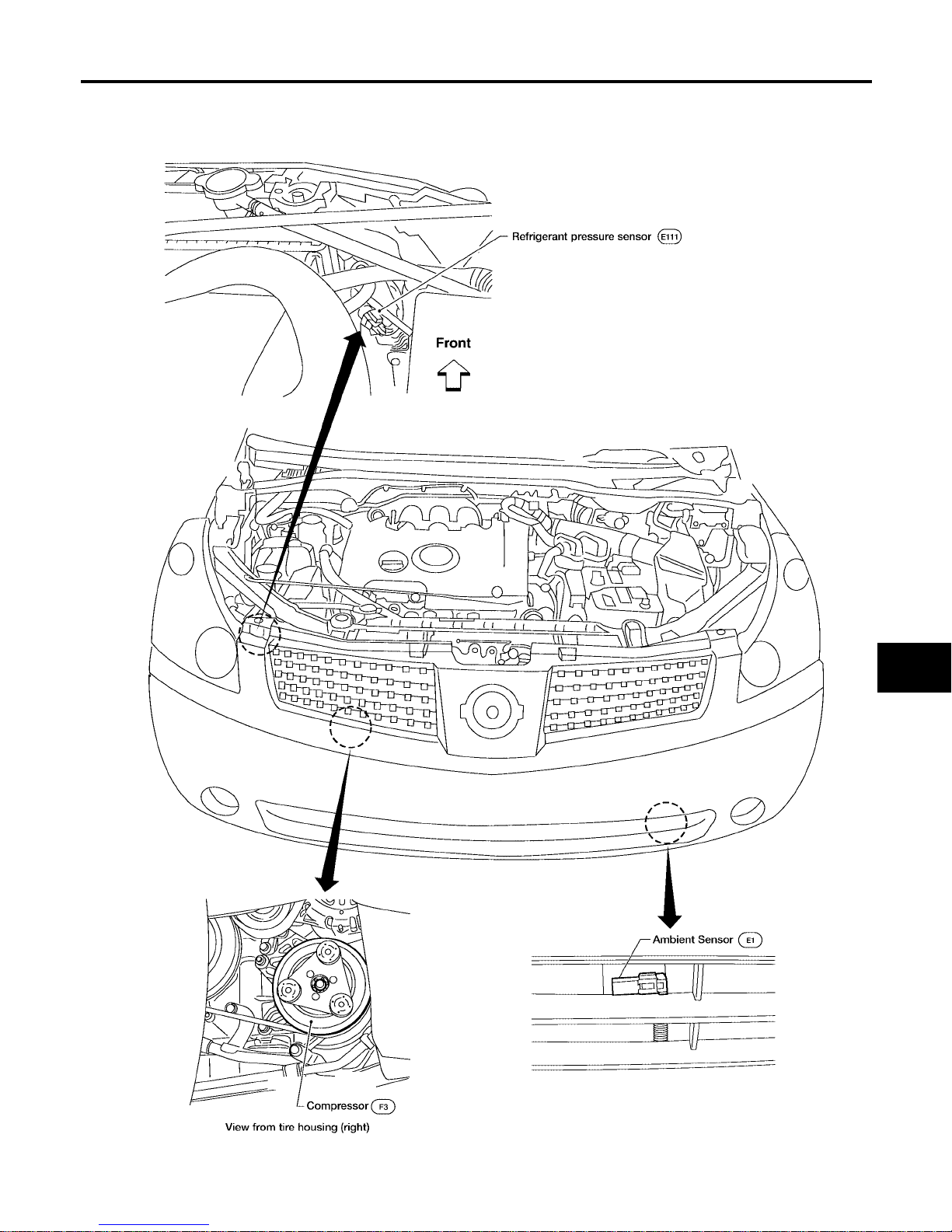
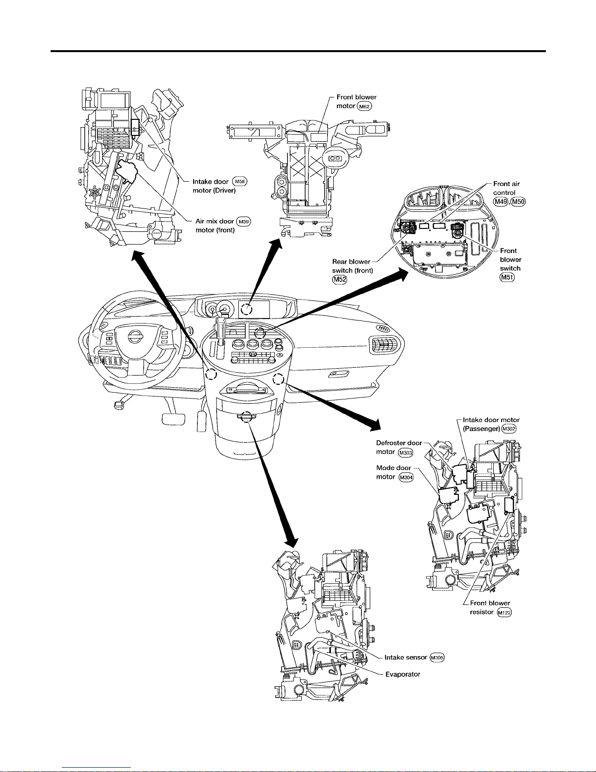
Component Parts and Harness Connector Location EJS001S B
ENGINE COMPARTMENT
WJIA1604E
Page 36
MTC-36
TROUBLE DIAGNOSIS
Revision: January 2005 2004 Quest
FRONT P ASSENGER COMPARTMENT
WJIA0481E
Page 37
TROUBLE DIAGNOSIS
MTC-37
C
D
E
F
G
H
I
K
L
M
A
B
MTC
Revision: January 2005 2004 Quest
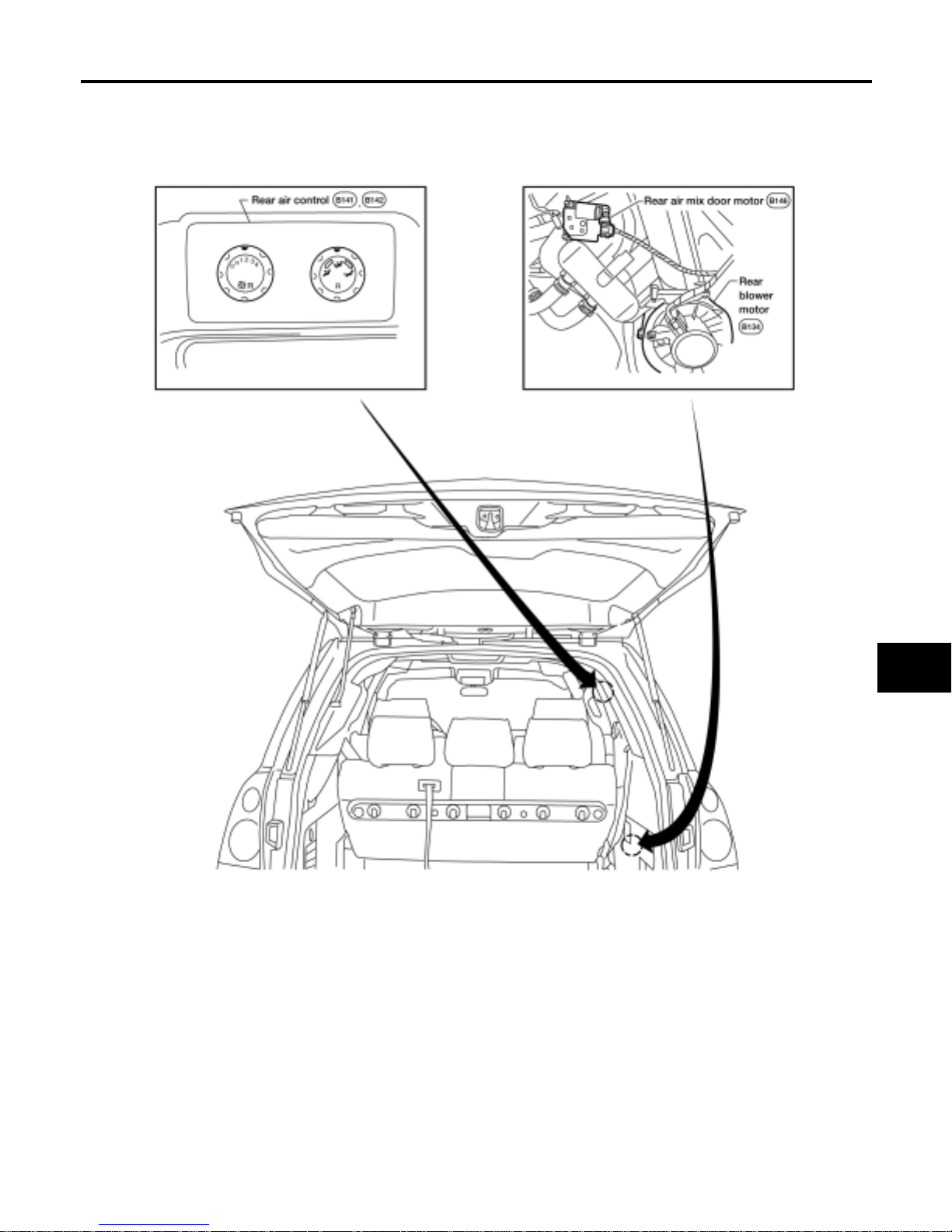
REAR PASSENGER COMPARTMENT
LJIA0123E
Page 38
MTC-38
TROUBLE DIAGNOSIS
Revision: January 2005 2004 Quest
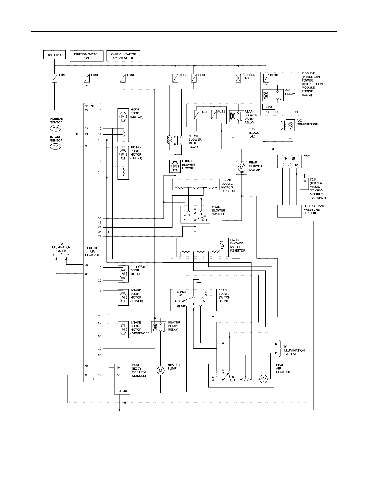
Schematic EJS001SC
WJWA0259E
Page 39
TROUBLE DIAGNOSIS
MTC-39
C
D
E
F
G
H
I
K
L
M
A
B
MTC
Revision: January 2005 2004 Quest
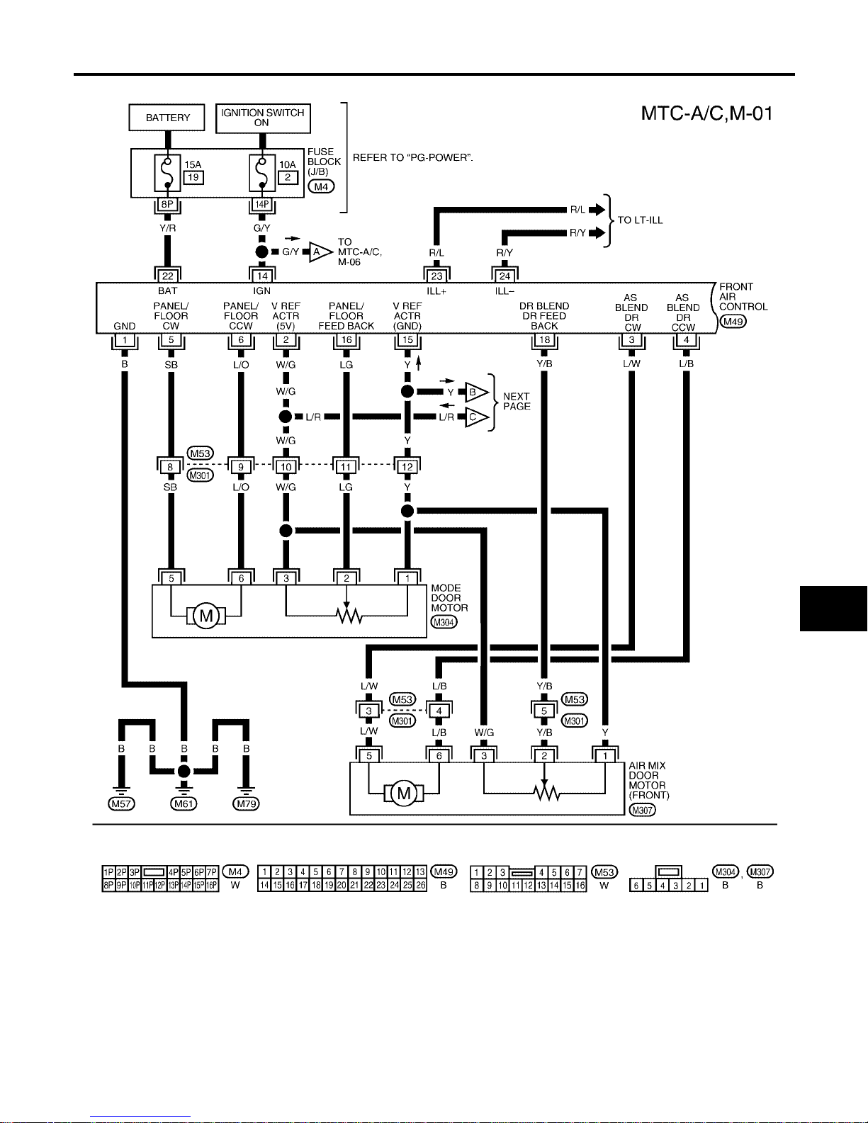
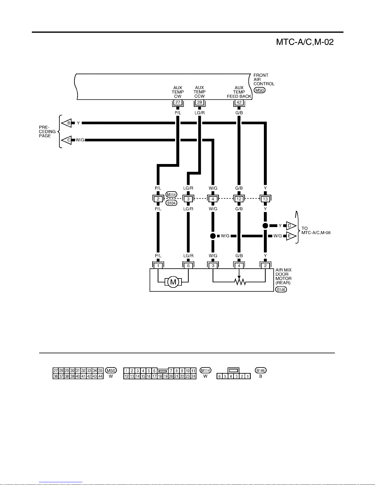
Wiring Diagram —A/C,M— EJS001SD
WJWA0260E
Page 40
MTC-40
TROUBLE DIAGNOSIS
Revision: January 2005 2004 Quest
WJWA0064E
Page 41
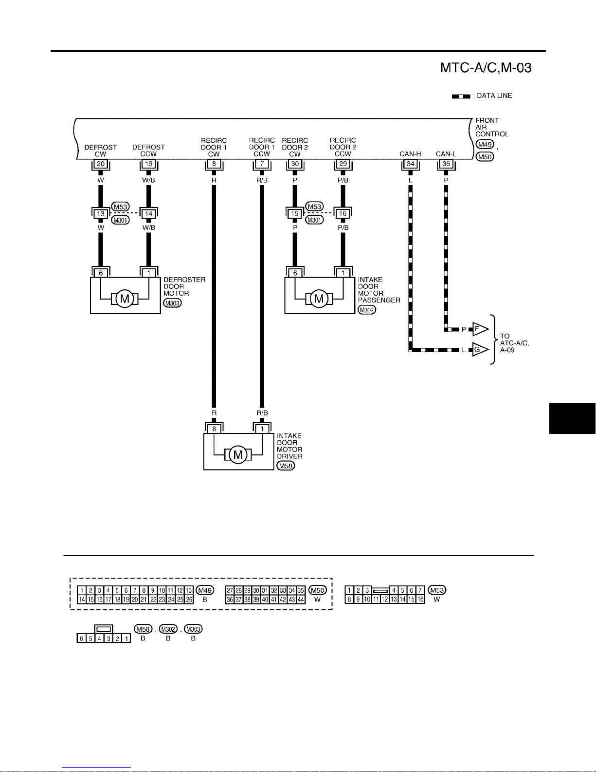
TROUBLE DIAGNOSIS
MTC-41
C
D
E
F
G
H
I
K
L
M
A
B
MTC
Revision: January 2005 2004 Quest
WJWA0265E
Page 42
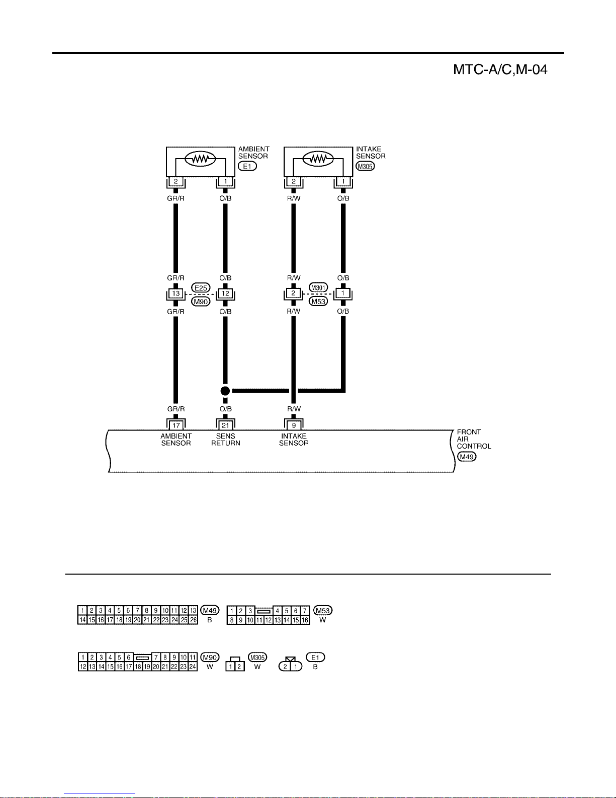
MTC-42
TROUBLE DIAGNOSIS
Revision: January 2005 2004 Quest
WJWA0266E
Page 43
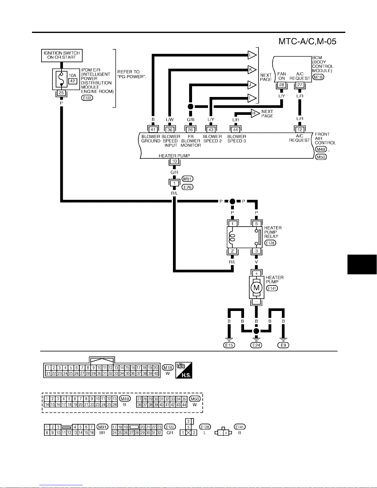
TROUBLE DIAGNOSIS
MTC-43
C
D
E
F
G
H
I
K
L
M
A
B
MTC
Revision: January 2005 2004 Quest
WJWA0176E
Page 44
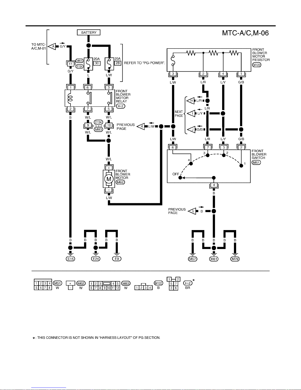
MTC-44
TROUBLE DIAGNOSIS
Revision: January 2005 2004 Quest
WJWA0261E
Page 45
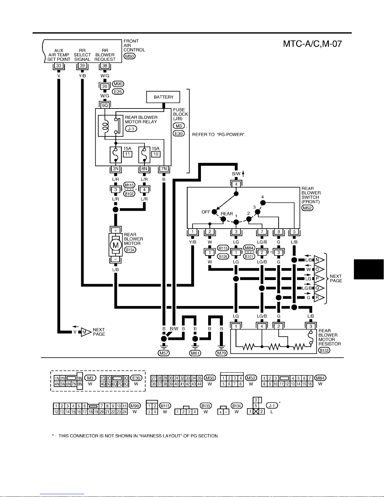
TROUBLE DIAGNOSIS
MTC-45
C
D
E
F
G
H
I
K
L
M
A
B
MTC
Revision: January 2005 2004 Quest
WJWA0262E
Page 46
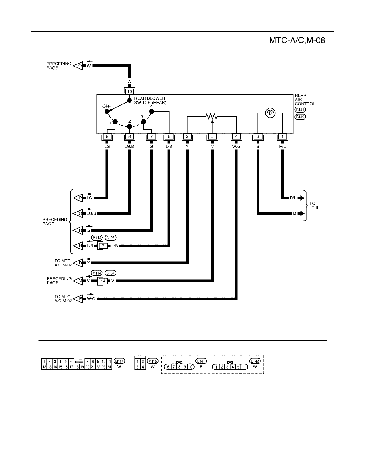
MTC-46
TROUBLE DIAGNOSIS
Revision: January 2005 2004 Quest
WJWA0263E
Page 47
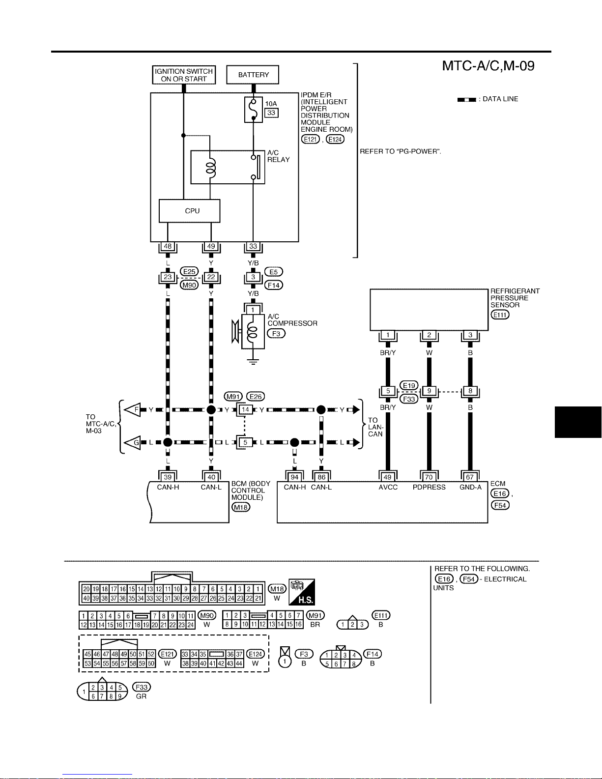
TROUBLE DIAGNOSIS
MTC-47
C
D
E
F
G
H
I
K
L
M
A
B
MTC
Revision: January 2005 2004 Quest
WJWA0264E
Page 48
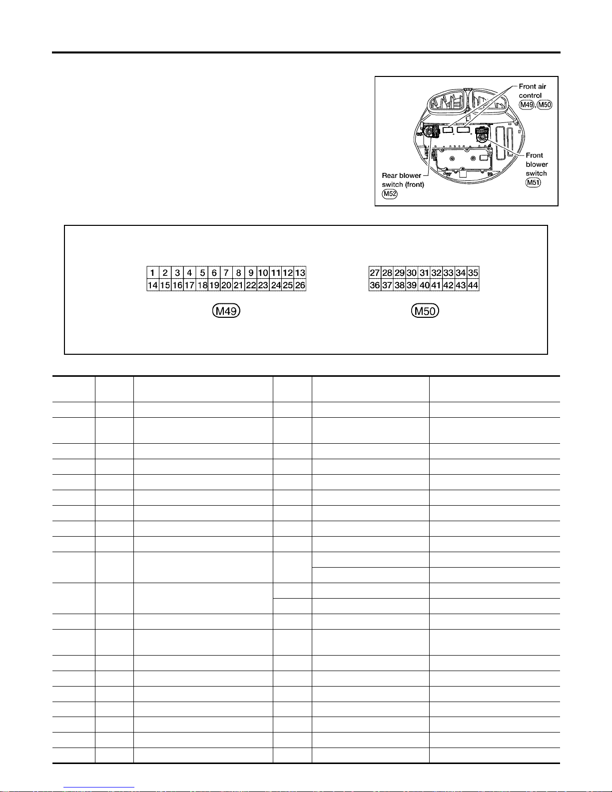
MTC-48
TROUBLE DIAGNOSIS
Revision: January 2005 2004 Quest
Front Air Control Terminals and Reference Value EJS001SE
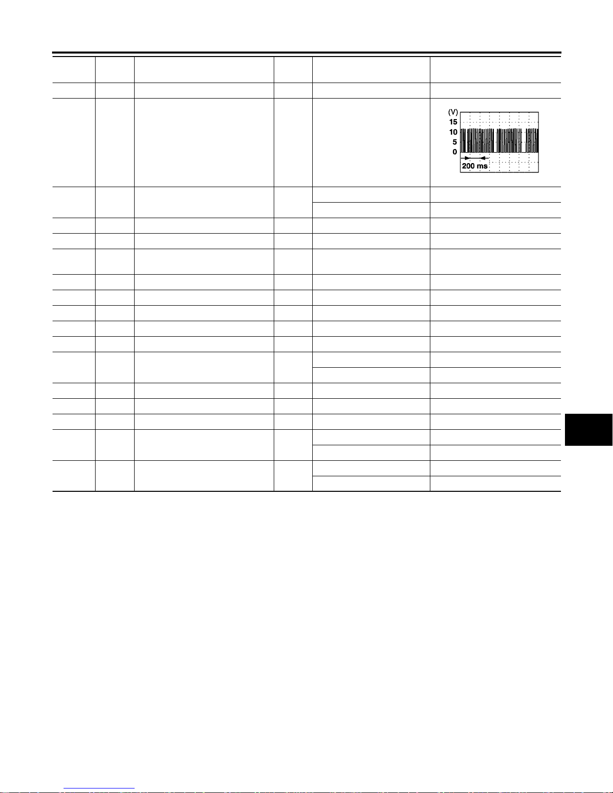
Measure voltage between each terminal and ground by following
Terminals and Reference Value for front air control
PIN CONNECTOR TERMINAL LAYOUT
TE RMINALS AND REFERENCE VALUE FOR FRONT AIR CONTROL
LJIA0126E
WJIA0402E
Termi-
nal No.
Wire
Color
Item
Ignition
Switch
Condition
Voltage (V)
(Approx.)
1 B Ground - - 0V
2W/G
Position balanced resistor (PBR)
power
ON - 5V
3 L/W Front air mix door motor CW ON Clockwise rotation Battery voltage
4 L/B Front air mi x d o or motor CCW ON Counterclockwise ro tation Battery voltage
5 SB Mode door motor CW ON Clockwise rotation Battery voltage
6 L/O Mode door motor CCW ON Counterclockwise rotation Battery voltage
7 R/B Intake door motor (driver) CCW ON Clockwise rotation Battery voltage
8 R Intake door motor (driver) CW ON Counterclockwise rotation Battery voltage
9 R/W Intake sensor ON - 0 - 5V
10 R/L Heat Pump ON
Heater pump OFF Batter voltage
Heater pump ON 0V
12 L/R Compressor ON signal
ON A/C switch OFF 5V
ON A/C switch ON 0V
14 G/Y Power supply for IGN ON - Battery voltage
15 Y
Position balanced resistor (PBR)
ground
ON - 0V
16 LG Mode door motor feedback ON - 0 - 5V
17 GR/R Ambient sensor ON - 0 - 5V
18 Y/B Front air mix door motor feedback
19 W/B Defroster door motor CC W ON Counterclockwise rotation Battery voltage
20 W Defroster do or m ot or CW ON Clockwise rotation Battery voltage
21 O/B Sensor return ON - 0 - 5V
22 Y/R Power supply for BAT - - Battery voltage
Page 49
TROUBLE DIAGNOSIS
MTC-49
C
D
E
F
G
H
I
K
L
M
A
B
MTC
Revision: January 2005 2004 Quest
23 R/L Illumination + ON Park lamps ON Battery voltage
24 R/Y Illumination - - Park lamps ON
26 G/B Front blower monitor (speed 1) ON
Front blower motor OFF Battery voltage
Front blower motor ON 0 - 5V
27 P/L Air mix door motor (rear ) CW ON Clockwise rotation Battery voltage
28 LG/R Air mix door mo to r (rear ) CCW ON Counterclockwise rotation Battery voltage
29 P/B
Intake door motor (passenger)
CCW
ON Counterclockwise rotation Battery voltage
30 P Intake door motor (passenger) CW ON Clockwise rotation Battery voltage
33 V Air mix door (rear) set point ON - 0 - 5V
34 L CAN-H ON - 0 - 5V
35 Y CA N -L ON - 0 - 5V
36 L/W Front blower speed input ON Clockwise rotation Battery voltage
38 W/G Rear blower request ON
Front blower motor OFF Battery voltage
Front blower motor ON 0V
39 Y/B Rear select signal ON - 0V - Battery voltage
41 B Blower ground ON - 0 V
42 G/B Air mix doo r moto r (rear ) feedba ck ON - 0 - 5V
43 L/Y Front blower speed 2 ON
Front blower motor OFF Battery voltage
Front blower motor ON 0 - 5V
44 L/R Front blower speed 3 ON
Front blower motor OFF Battery voltage
Front blower motor ON 0 - 5V
Termi-
nal No.
Wire
Color
Item
Ignition
Switch
Condition
Voltage (V)
(Approx.)
PIIA2344E
Page 50
MTC-50
TROUBLE DIAGNOSIS
Revision: January 2005 2004 Quest
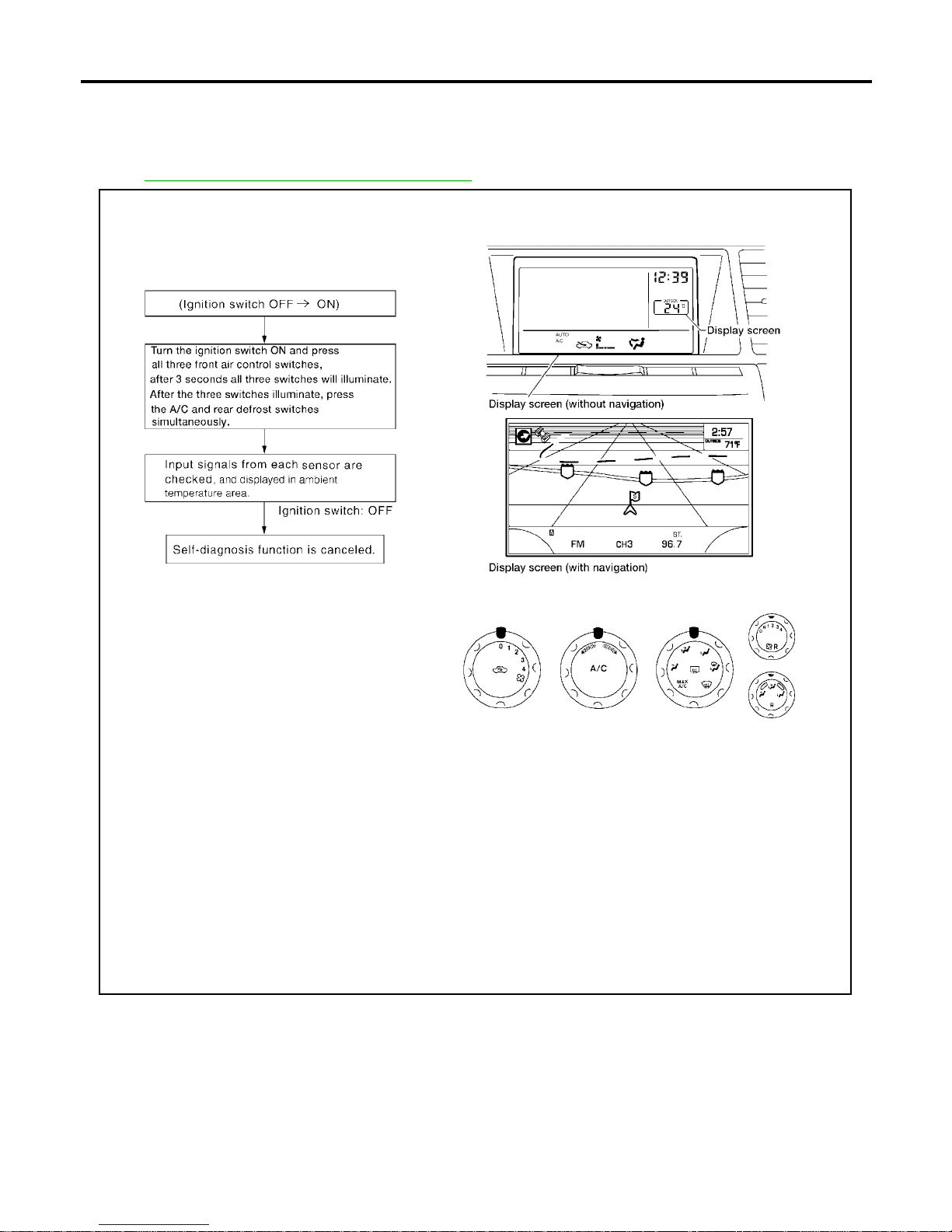
A/C System Self-diagnosis Function EJS001SF
DESCRIPTION
The self-diagno stic system diagno ses sensors, door motors, blower mot or, etc. Refer to applicable se ctions
(items) for details. Fault c odes (if any ar e presen t) will be dis played in the am bient t emperat ure disp lay are a.
Refer to MTC-51, "
SELF-DIAGNOSIS CODE CHART" .
WJIA0486E
Page 51

TROUBLE DIAGNOSIS
MTC-51
C
D
E
F
G
H
I
K
L
M
A
B
MTC
Revision: January 2005 2004 Quest
SELF-DIAGNOSIS CODE CHART
Code No. Reference page
02 EE changed by calibration MTC-11 6, "
FRONT AIR CONTROL"
03 Battery voltage out of range SC-4, "BATTERY"
04 Mode switch circuit open or short MTC-11 6, "FRONT AIR CONTROL"
05 Blower motor failure MTC-72, "Front Blower Motor Circuit"
20 BCM not responding to A/C request
ATC-100, "
DIAGNOSTIC PROCEDURE FOR MAGNET
CLUTCH"
21 BCM not responding to rear defroster request GW-84, "REAR WINDOW DEFOGGER"
22 Air mix door mo tor (front) circu it failure
MTC-62, "
DIAGNOSTIC PROCEDURE FOR AIR MIX DOOR
MOTOR (FRONT)"
30 In-vehicle sensor circuit out of range (low)
ATC-120, "
In-vehicle Sensor Circuit"
31 In-vehicle sensor circuit out of range (high)
34 Front potentio temperature control (PTC) failure MTC-116, "
FRONT AIR CONTROL"
36 Air mix door motor (front) P B R circuit failu re
MTC-62, "
DIAGNOSTIC PROCEDURE FOR AIR MIX DOOR
MOTOR (FRONT)"
38 Air mix door motor (rear) circuit failure
MTC-64, "
DIAGNOSTIC PROCEDURE FOR AIR MIX DOOR
MOTOR (REAR)"
40 Ambient sensor circuit open
M TC-111, "
Ambient Sensor Circuit"
41 Ambient sensor circuit short
56 Intake sensor circuit short
MTC-11 3, "
Intake Sensor Circuit"
57 Intake sensor circuit open
62 Defroster door motor circuit failure MTC-70, "
Defroster Door Motor Circuit"
72 Intake door motor (passenger) circuit failure
MTC-69, "
DIAGNOSTIC PROCEDURE FOR INTAKE DOOR
MOTOR (PASS ENGER)"
80 CAN bus fault
LAN-6, "
CAN COMMUNICATION"
81 CAN BCM message missin g
82 Intake door motor (motor) circuit failure
MTC-68, "
DIAGNOSTIC PROCEDURE FOR INTAKE DOOR
MOTOR (DRIVER)"
90 Stuck switch MTC-11 6, "FRONT AIR CONTROL"
92 Mode door motor circuit failure MTC-57, "Mode Door Motor Circuit"
Page 52
MTC-52
TROUBLE DIAGNOSIS
Revision: January 2005 2004 Quest
Operational Check EJS001SG
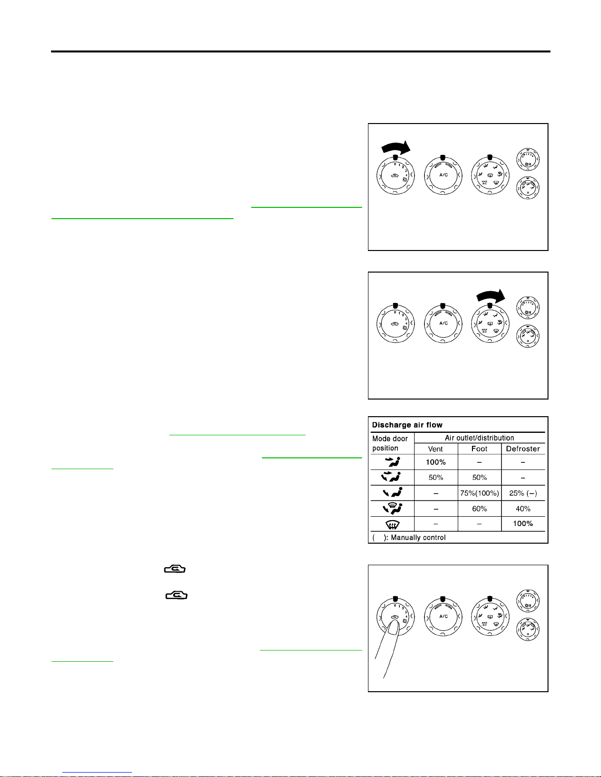
The purpose of the operational check is to confirm that the sys tem operates properly.
CHECKING BLOWER
1. Turn blower control dial clockwise. Blower should operate on
low speed. The fan symbol should have one blade lit (on display).
2. Turn t h e blow e r co nt ro l di al a ga in , a nd co nt inu e che ck in g bl ow er
speed and fan symbol until all speeds are checked.
3. Leave blower on maximum speed.
If NG, g o to trouble diag no sis procedure for MT C -74 , "
DIAGNOSTIC
PROCEDURE FOR BLOWER MOTOR"
If OK, continue with next check.
CHECKING DISCHARGE AIR
1. Turn the mode switch.
2. Each position indicator should change shape (on display).
3. Confirm that discharge air comes out according to the air distri-
bution table. Refer to MTC-28, "
Discharge Air Flow" .
Mode door position is checked in the next step.
If NG, go to trouble diagnosis procedure for MTC-57, "
Mode Door
Motor Circuit" .
If OK, continue with next check.
NOTE:
Confirm that the compressor clutch is engaged (sound or visual
inspection) and i ntake doo r po sitio n is at fresh w hen th e DEF or D/F
is selected.
CHECKING RECIRCULATION
1. Press recirc ulati on ( ) switch one time. Recir cula tion in dica -
tor should illuminate.
2. Press recirculation ( ) switch one more time. Recirculation
indicator should go off.
3. Listen for intake door position change (blower sound should
change slightly).
If NG, go to tr ouble diagnosis procedure for MTC-67, "
Intake Door
Motor Circuit" .
If OK, continue with next check.
NOTE:
Confirm that the compressor clutch is engaged (sound or visual
inspection) and intake door position is at fresh when the DEF or D/F is selected.
Conditions : Engine running and at normal operating temperature
WJIA0487E
WJIA0488E
WJIA0528E
WJIA0489E
Page 53
TROUBLE DIAGNOSIS
MTC-53
C
D
E
F
G
H
I
K
L
M
A
B
MTC
Revision: January 2005 2004 Quest
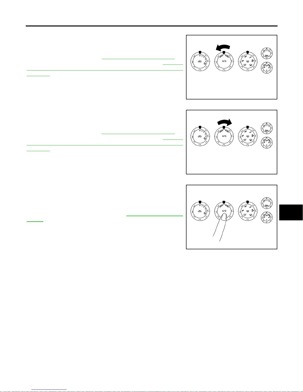
CHECKING TEMPERATURE DECREASE
1. Rotate temperature dial counterclockwise .
2. Check for cold air at appropriate d ischarge air outlets.
If NG, listen for sound of air mix door motor operation if OK, go to
trouble diagnosi s procedure for MTC-100, "
Insufficient Coolin g" . If
air mix door motor appears to be malfunctioning, go to MTC-62,
"DIAGNOSTIC PROCEDURE FOR AIR MIX DOOR MOTOR
(FRONT)" .
If OK, continue with next check.
CHECKING TEMPERATURE INCREASE
1. Rotate temperature dial clockwise.
2. Check for hot air at appropriate discharge air outlets.
If NG, lis ten for sound of air mix door motor o peration. If OK, go to
trouble diagnosis procedure for MTC-108, "
Insufficient Hea ting" . If
air mix door motor appears to be malfunctioning, go to MTC-62,
"DIAGNOSTIC PROCEDURE FOR AIR MIX DOOR MOTOR
(FRONT)" .
If OK, continue with next check.
CHECK A/C SWITCH
1. Press A/C switch with the blower dial set to 2 speed.
2. A/C switc h in dic a tor will turn ON .
● Confirm that the compressor clutch engages (sound or visual
inspection).
If NG, go to trouble dia gn os is proc ed ur e for MTC- 94, "
Magnet Clutch
Circuit" .
If OK, continue with next check.
WJIA0490E
WJIA0491E
WJIA0492E
Page 54
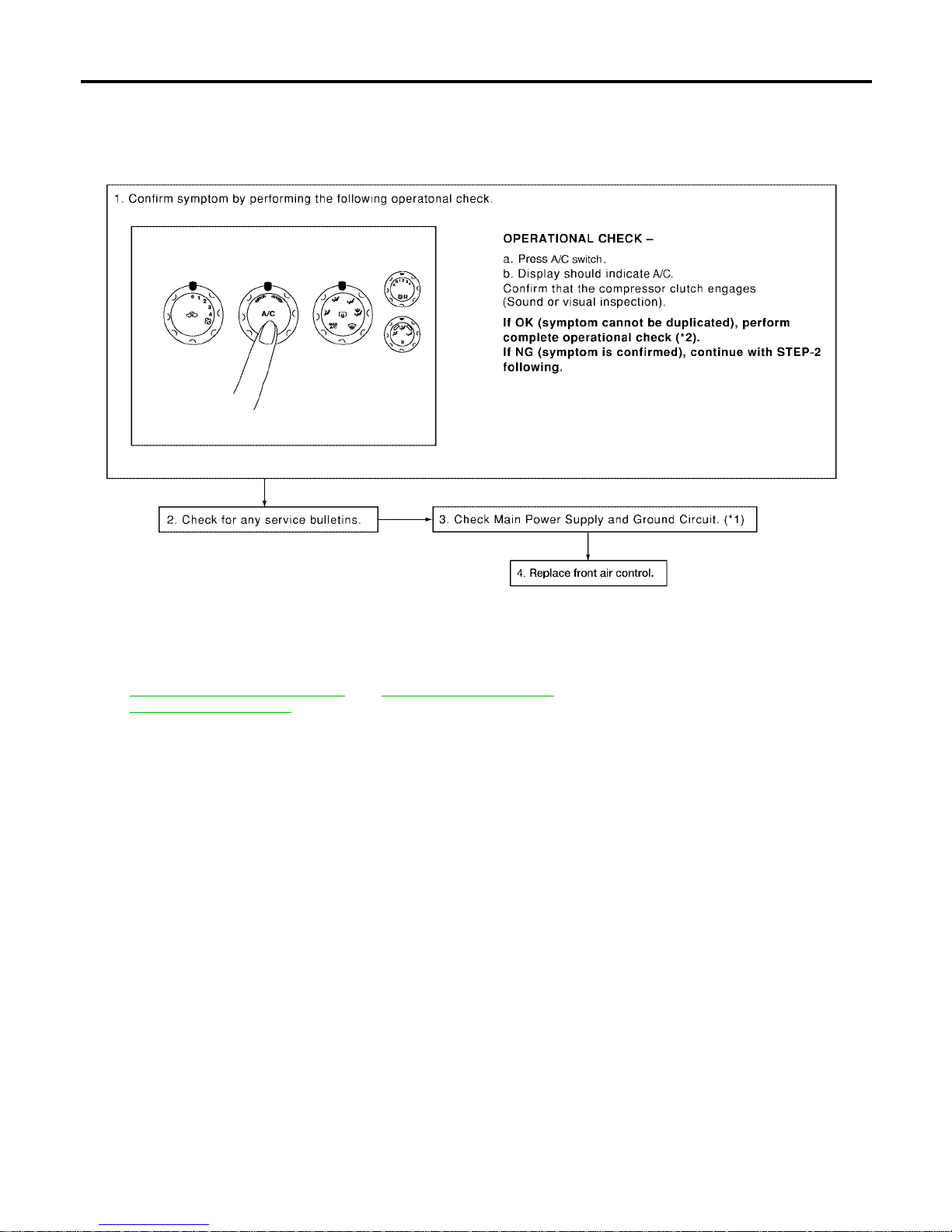
MTC-54
TROUBLE DIAGNOSIS
Revision: January 2005 2004 Quest
Power Supply and Ground Circuit for Front Air Control EJS001SH
SYMPTO M: A/C system does not come on.
INSPECTION FLOW
*1 MTC-54, "Power Supply and Ground
Circuit for Front Air Co n trol"
*2 MTC-52, "Operational Check".
WJIA1027E
Page 55
TROUBLE DIAGNOSIS
MTC-55
C
D
E
F
G
H
I
K
L
M
A
B
MTC
Revision: January 2005 2004 Quest
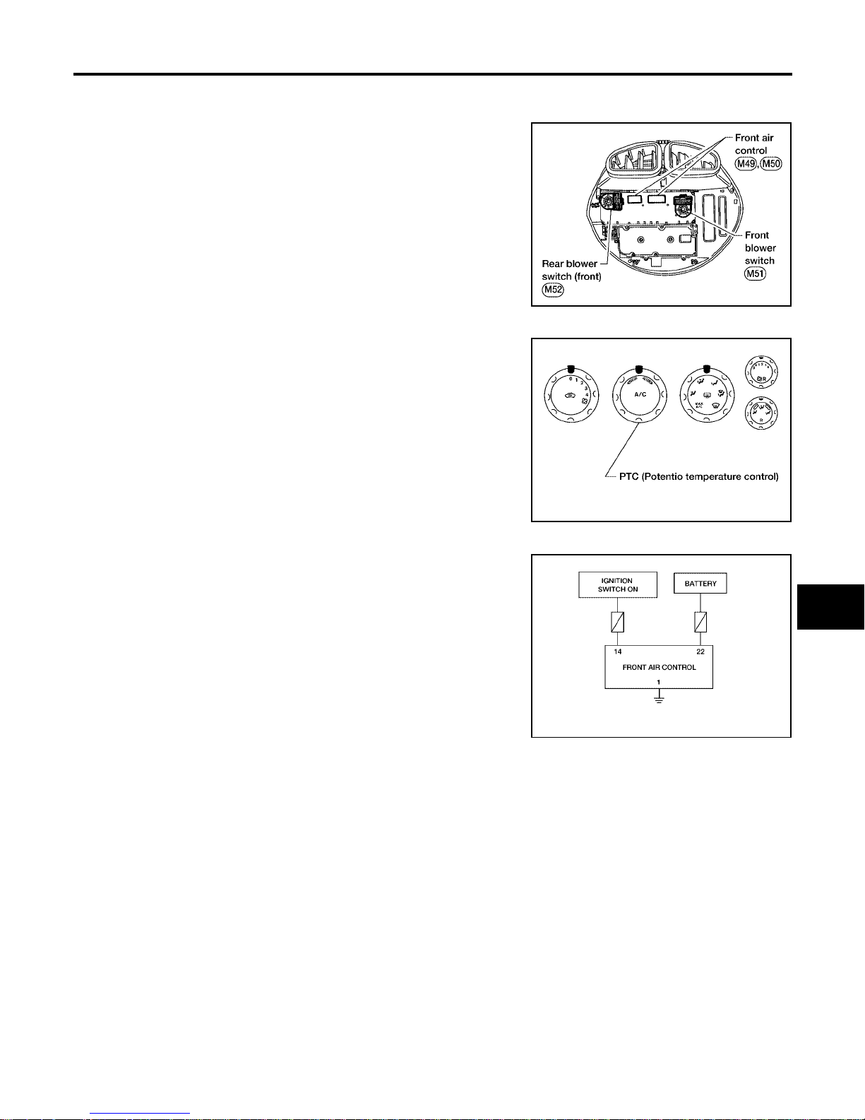
COMPONENT DESCRIPTION
Front Air Control
The front air contro l has a built-in microcompute r which processes
information sent from various sensors needed for air conditioner
operation. The air mix door motors, mode door motor, intake door
motors, defroster door motor, blower motor and compressor are then
controlled.
The front air control is unitized with control mechanisms. When the
various switches and temperature dials are operated, data is input to
the front air control.
Self-diagnostic functions are also built into the front air control to provide quick check of malfunctions in the air conditioner system.
Potentio Temp erature Control (PTC)
The PTC is built into the front a ir control. It can be set from co ld to
hot or any intermediate position by rotating the temperature dial.
DIAGNOSTIC PROCEDURE FOR A/C SYSTEM
SYMPTOM: A/C system does not come on.
LJIA0126E
WJIA0494E
WJIA0414E
Page 56
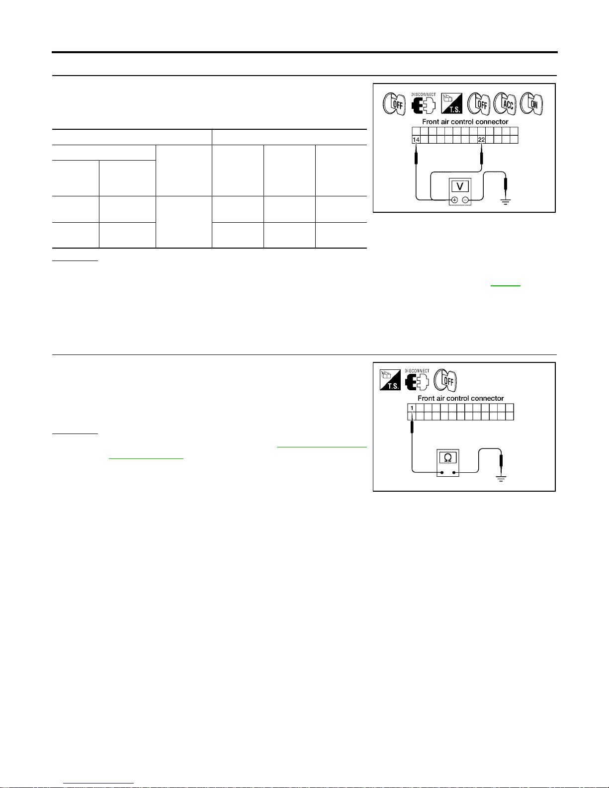
MTC-56
TROUBLE DIAGNOSIS
Revision: January 2005 2004 Quest
1. CHECK POWER SUPPLY CIRCUITS FOR FRONT AIR CONTROL
1. Disconnect fr ont air control connector.
2. Check voltage between front air control harness connector M49
terminals 14 (G/Y) and 22 (Y/R), and ground.
OK or NG
OK >> GO TO 2.
NG >> Check 10A and 15A fuses [Nos. 2 and 19, located in the fuse block (J/B)]. Refer to PG-71
.
● If fuses are OK, check harness for open circuit. Repair or replace as necessary.
● If fuses a re NG, re place fuse and check harness for sh ort circuit . Repair or repla ce as neces -
sary.
2. CHECK GROUND CIRCUIT FOR FRONT AIR CONTROL
1. Turn ignition switch OFF.
2. Check continuity between front air control harness connector
M49 terminal 1 (B) and ground.
OK or NG
OK >> Replace front air control. Refer to MTC-116, "FRONT
AIR CONTROL" .
NG >> Repair harness or connector.
Terminals Ignition switch position
(+)
(-) OFF ACC ON
front air
control
connector
Terminal No.
(Wire color)
M49 14 (G/Y)
Ground
Approx. 0V Approx. 0V
Battery
voltage
M49 22 (Y/R)
Battery
voltage
Battery
voltage
Battery
voltage
WJIA0415E
Continuity should exist.
WJIA1588E
Page 57
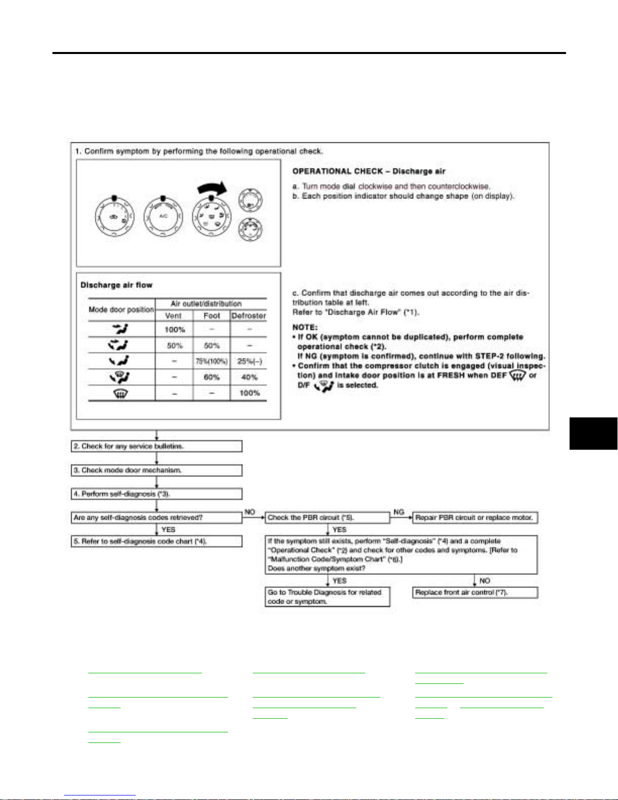
TROUBLE DIAGNOSIS
MTC-57
C
D
E
F
G
H
I
K
L
M
A
B
MTC
Revision: January 2005 2004 Quest
Mode Door Motor Circuit EJS001SI
SYMPTOM:
● Air outlet does not change.
● Mode door motor does not operate normally.
INSPECTION FLOW
*1 MTC-28, "Discharge Air Flow".*2MTC-52, "Operational Check".*3MTC-50, "A/C System Self-diagno-
sis Function".
*4 MTC-51, "SELF-DIAGNOSIS CODE
CHART".
*5 MTC-58, "
DIAGNOSTIC PROCEDURE FOR MODE DOOR
MOTOR"
*6 MTC-51, "SELF-DIAGNOSIS CODE
CHART" or MTC-33, "SYMPTOM
TABLE"
*7 MTC-51, "SELF-DIAGNOSIS CODE
CHART".
WJIA1611E
Page 58
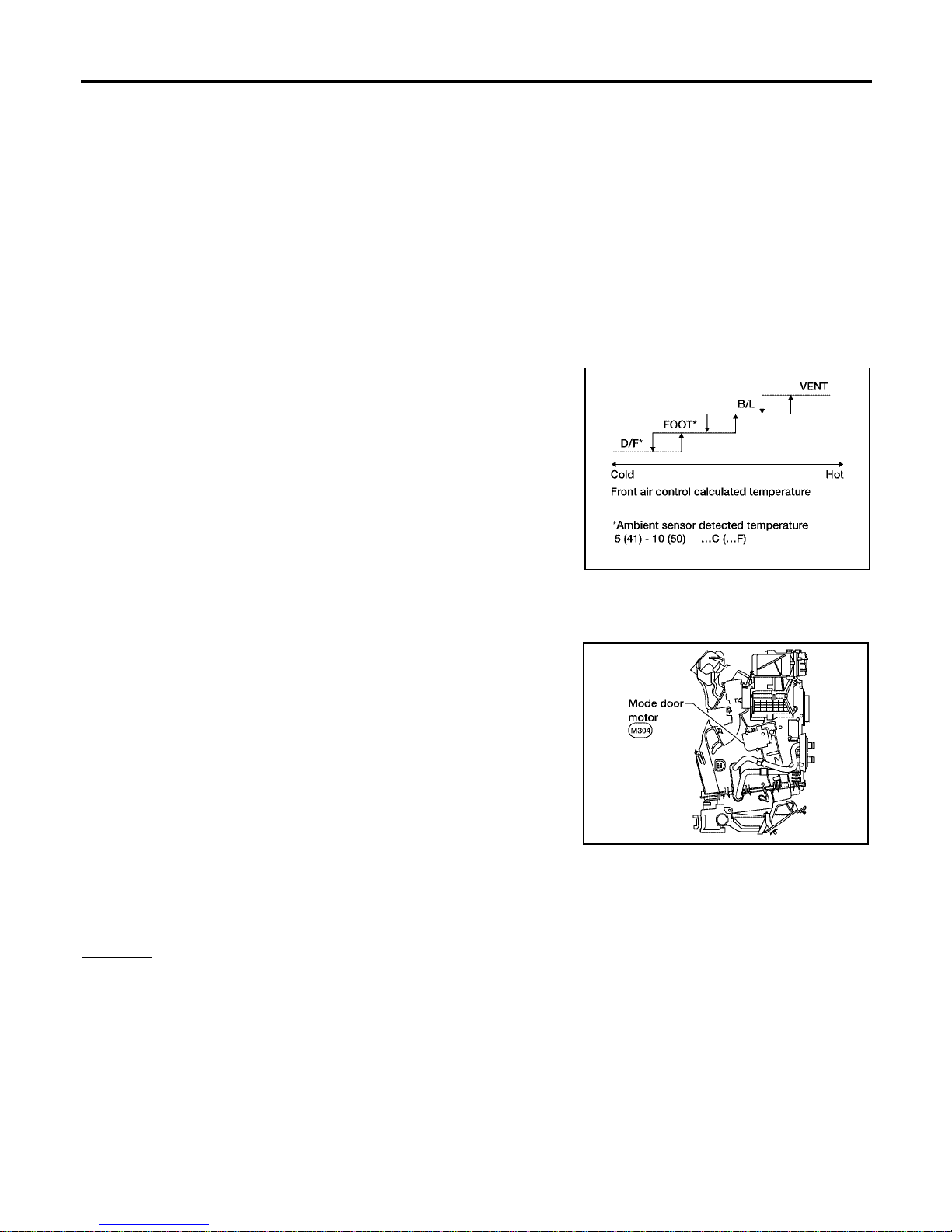
MTC-58
TROUBLE DIAGNOSIS
Revision: January 2005 2004 Quest
SYSTEM DESCRIPTION
Component Parts
Mode door control system components are:
● Front air control
● Mode door motor
● PBR (built into mode door motor)
System Operation
The mode door position (vent, B/L, foot, and defrost) is set by the front air control by means of the mode door
motor. When a mode door position is selected on the front air control, voltage is applied to one circuit of the
mode door motor while ground is applied to the other circuit, causing the mode door motor to rotate. The direction of rotation is determined by which circuit has voltage applied to it, and which one has ground applied to it.
The front air control monitor s the mode door position by measuring the voltage signal on the PBR circuit.
Mode Door Control Specification
COMPONENT DESCRIPTION
Mode Door Motor
The mode door motor is attached to the heater & cooling unit. It
rotates so that ai r is discharged from the outlet set by the fron t air
control Motor rotation is conveyed to a link which activates the mode
door.
DIAGNOSTIC PROCEDURE FOR MODE DOOR MOTOR
1. CHECK RESULT FROM FRONT AIR CONTROL SELF-DIAGNOSIS
Self-diagn osis code 92 is present.
Yes or No
Yes > >GO TO 2.
No >> GO TO 3.
WJIA0434E
WJIA0424E
Page 59
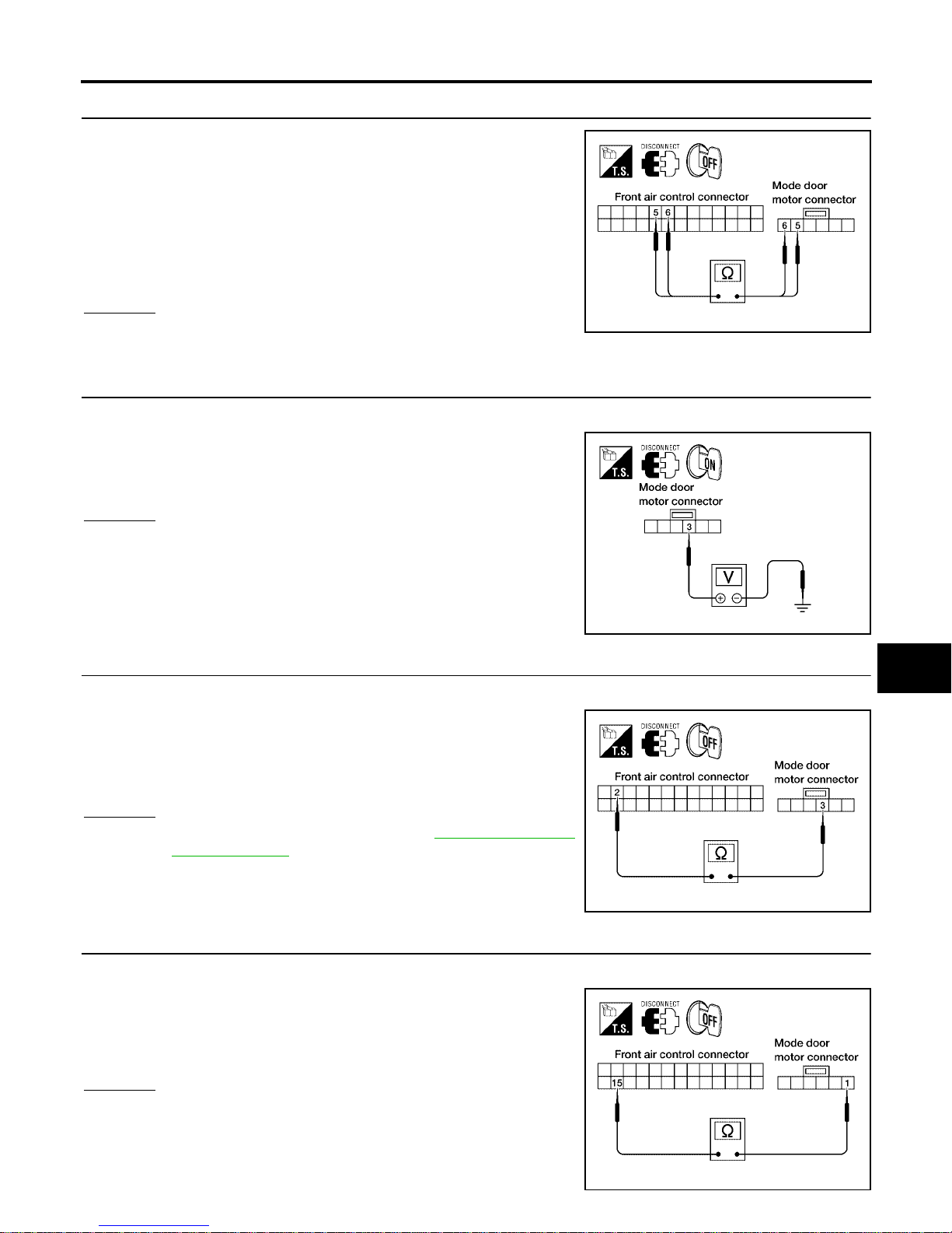
TROUBLE DIAGNOSIS
MTC-59
C
D
E
F
G
H
I
K
L
M
A
B
MTC
Revision: January 2005 2004 Quest
2. CHECK POWER SUPPLY AND GROUND CIRCUITS FOR MODE DOOR MOTOR
1. Disconnect front air control connector and mode door motor
connector.
2. Check continuity between front air control harness connector
M49 terminal 5 (SB) and m ode door motor c onnector M 304 te rminal 5 (SB) and between front air control harness connector
M49 terminal 6 (L/O) and mode door motor connector M304 terminal 6 (L/O).
OK or NG
OK >> Replace mode door mo tor.
NG >> Repair or replace harness as necessary.
3. CHECK PBR REFERENCE SIGNAL VOLTAGE
1. Disconnect the mode door motor harness connector.
2. Check voltage between mode door motor harness connector
M304 terminal 3 (W/G) and ground.
OK or NG
OK >> GO TO 5.
NG >> GO TO 4.
4. CHECK PBR REFERENCE VOLTAGE CIRCUIT BETWEEN MODE DOOR AND FRONT AIR CONTROL
1. Disconnect the front air control harness connector.
2. Check continuity between mod e door motor harness conn ector
M304 terminal 3 (W /G) and front air control harness connector
M49 terminal 2 (W/G).
OK or NG
OK >> Replace front air control. Refer to MTC-116, "FRONT
AIR CONTROL" .
NG >> Repair or replace harness as necessary.
5. CHECK PBR GROUND REFERENCE CIRCUIT
1. Disconnect the front air control harness connector.
2. Check continuity between mod e door motor harness conn ector
M304 terminal 1 (Y) and front air control harness connector M49
terminal 15 (Y).
OK or NG
OK >> GO TO 6.
NG >> Repair or replace harness as necessary.
Continuity should exist.
LJIA0027E
5V (Approx.) should exist.
LJIA0028E
Continuity should exist.
LJIA0029E
Continuity should exist.
LJIA0031E
Page 60
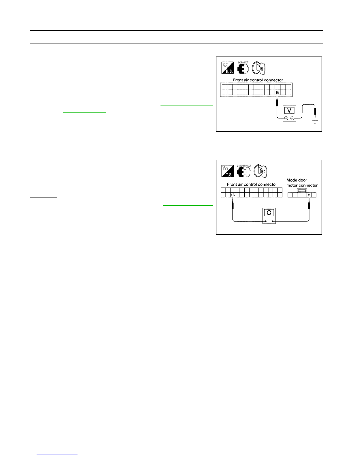
MTC-60
TROUBLE DIAGNOSIS
Revision: January 2005 2004 Quest
6. CHECK PBR FEEDBACK SIGNAL
1. Reconnect the front air cont rol harness connector and mode door motor conne ctor .
2. Check voltage between front air control harness connector M49
terminal 16 (LG) and ground.
3. Cycle mode switch through all modes.
OK or NG
OK >> Replace front air control. Refer to MTC-116, "FRONT
AIR CONTROL" .
NG >> GO TO 7.
7. CHECK PBR FEEDBACK CIRCUIT
1. Disconnect the mode door motor harness connector and front air control harness connector.
2. Check continuity between mode door motor harness connector
M304 terminal 2 (LG) and front air control harness connector
M49 terminal 16 (LG).
OK or NG
OK >> Replace mode door motor. Refer to MTC-133, "MODE
DOOR MOTOR" .
NG >> Repair or replace harness as necessary.
0V - 5V (Approx.) should exist.
LJIA0032E
Continuity should exist.
LJIA0034E
Page 61
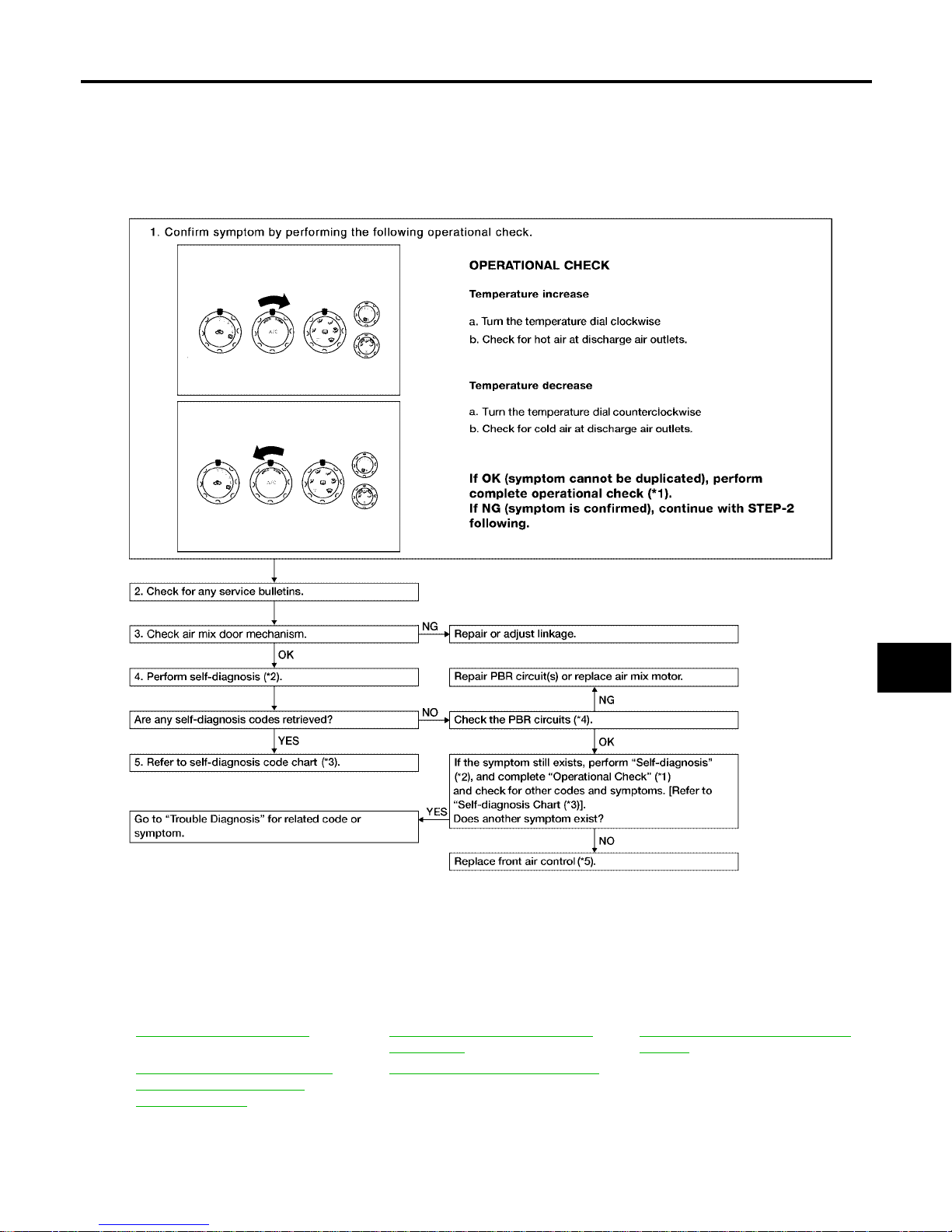
TROUBLE DIAGNOSIS
MTC-61
C
D
E
F
G
H
I
K
L
M
A
B
MTC
Revision: January 2005 2004 Quest
Air Mix Door Motor Circuit EJS001SJ
SYMPTOM:
● Discharge air temperature does not change.
● Air mix door motor does not operate.
INSPECTION FLOW
*1 MTC-52, "Operational Check".*2MTC-50, "A/C System Self-diagno-
sis Function".
*3 MTC-51, "
SELF-DIAGNOSIS CODE
CHART".
*4 MTC-62, "DIAGNOSTIC PROCE-
DURE FOR AIR MIX DOOR
MOTOR (FRONT)".
*5 MTC-116, "FRONT AIR CONTROL"
WJIA1612E
Page 62
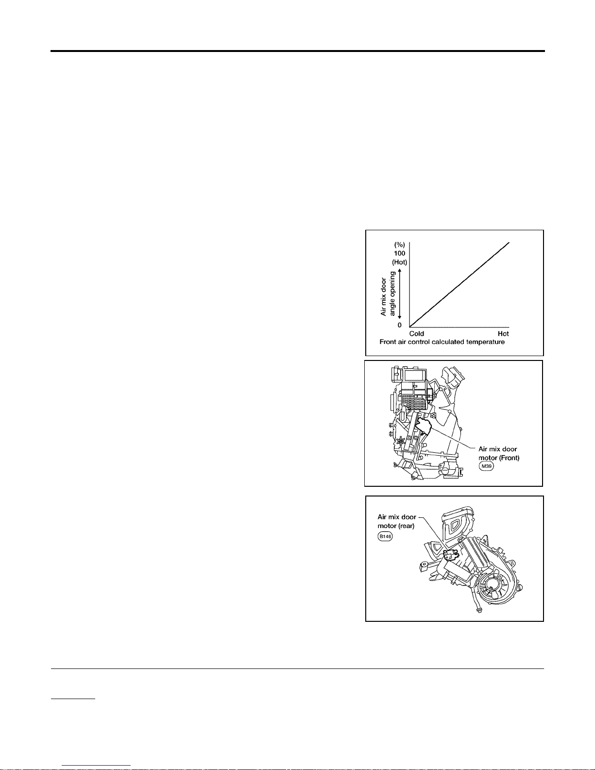
MTC-62
TROUBLE DIAGNOSIS
Revision: January 2005 2004 Quest
SYSTEM DESCRIPTION
Component Parts
Air mix door control system components are:
● Front air control
● Air mix door motors (Front and rear)
● PBR (built-into air mix motors)
System Operation
The front air control rec eives data from the temperature sel ected by the driver and rear passenge r. The front
air control then applies a voltage to one circuit of the appropriate air mix door motor, while ground is applied to
the other circu it, causi ng th e appro pri ate air mix d oor mot or t o rot ate . The di rec tion of rot ati on is deter min ed by
which circuit has v olt age a ppli ed t o it, a nd w hic h one ha s gro und a pplie d to i t. The fr ont ai r co ntrol moni tors the
air mix door positions by measuring the voltage signal on the PBR circuits of each door.
Air Mix Door Control Specification
COMPONENT DESCRIPTION
Air Mix Door Motors
The front air mix door motor is attached to the front heater & cooling
unit. The rear air mix door motor is attached to the rear heater &
cooling unit. These motors rotate so that the air mix door is opened
or closed to a position set by the front (or rear) air control. Motor
rotation is then convey ed through a shaf t and the air mix door position is then fed back to the front air control by the PBR built into the
air mix door motors.
DIAGNOSTIC PROCEDURE FOR AIR MIX DOOR MOTOR (FRONT)
1. CHECK RESULT FROM FRONT AIR CONTROL SELF-DIAGNOSIS
Self-diagn osis code 22 is present.
Yes or No
Yes > >GO TO 2.
No >> GO TO 3.
WJIA0435E
WJIA0496E
WJIA0498E
Page 63
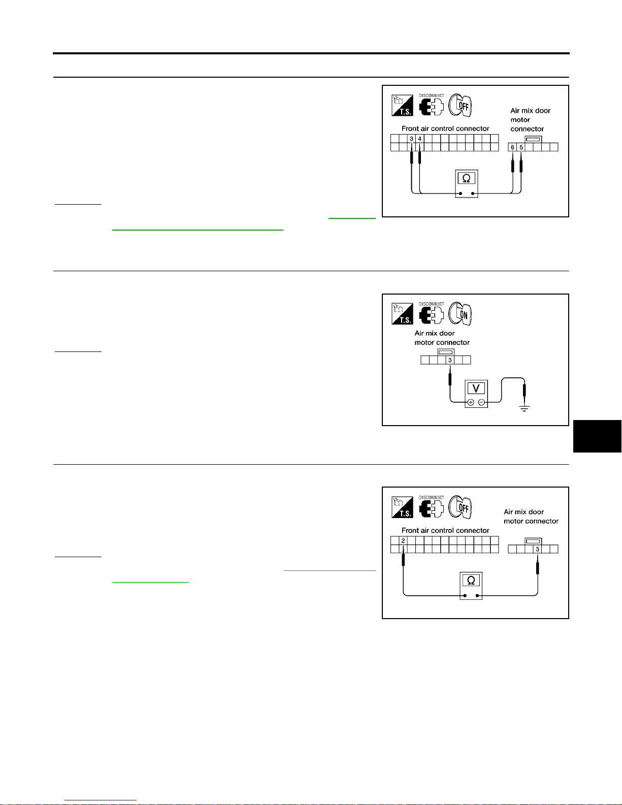
TROUBLE DIAGNOSIS
MTC-63
C
D
E
F
G
H
I
K
L
M
A
B
MTC
Revision: January 2005 2004 Quest
2. CHECK POWER SUPPLY CIRCUITS FOR AIR MIX DOOR MOTOR (FRONT)
1. Disconnect front air control connector and air mix door motor
(front) connector.
2. Check continuity between front air control harness connector
M49 terminal 3 (L/W) an d air mix door motor (front) connector
M39 terminal 5 (L/W) and betw een front air control harness connector M49 terminal 4 (L/B) and ai r mix door motor (front) connector M39 termi nal 6 (L/B).
OK or NG
OK >> Replace air mix door motor (front). Refer to MTC-135,
"AIR MIX DOOR MOTOR (FRONT)" .
NG >> Repair or replace harness as necessary.
3. CHECK PBR REFERENCE SIGNAL VOLTAGE
1. Disco nn ect the ai r mix door mo tor (front) harness connector.
2. Check voltage between air mix door motor (front) harness connector M39 terminal 3 (W/G) and ground.
OK or NG
OK >> GO TO 5.
NG >> GO TO 4.
4. CHECK PBR REFERENCE VOLTAGE CIRCUIT BETWEEN AIR MIX DOOR MOTOR (FRONT) AND
FRONT AIR CONTROL
1. Disconnect the front air control harness connector.
2. Check continuity between air mix door motor (front) harness
connector M39 terminal 3 (W/G) and front air control harness
connector M49 terminal 2 (W/G).
OK or NG
OK >> Replace front air control. Refer to MTC-116, "FRONT
AIR CONTROL" .
NG >> Repair or replace harness as necessary.
Continuity should exist.
WJIA0535E
5V (Approx.) should exist.
WJIA0536E
Continuity should exist.
WJIA0537E
Page 64
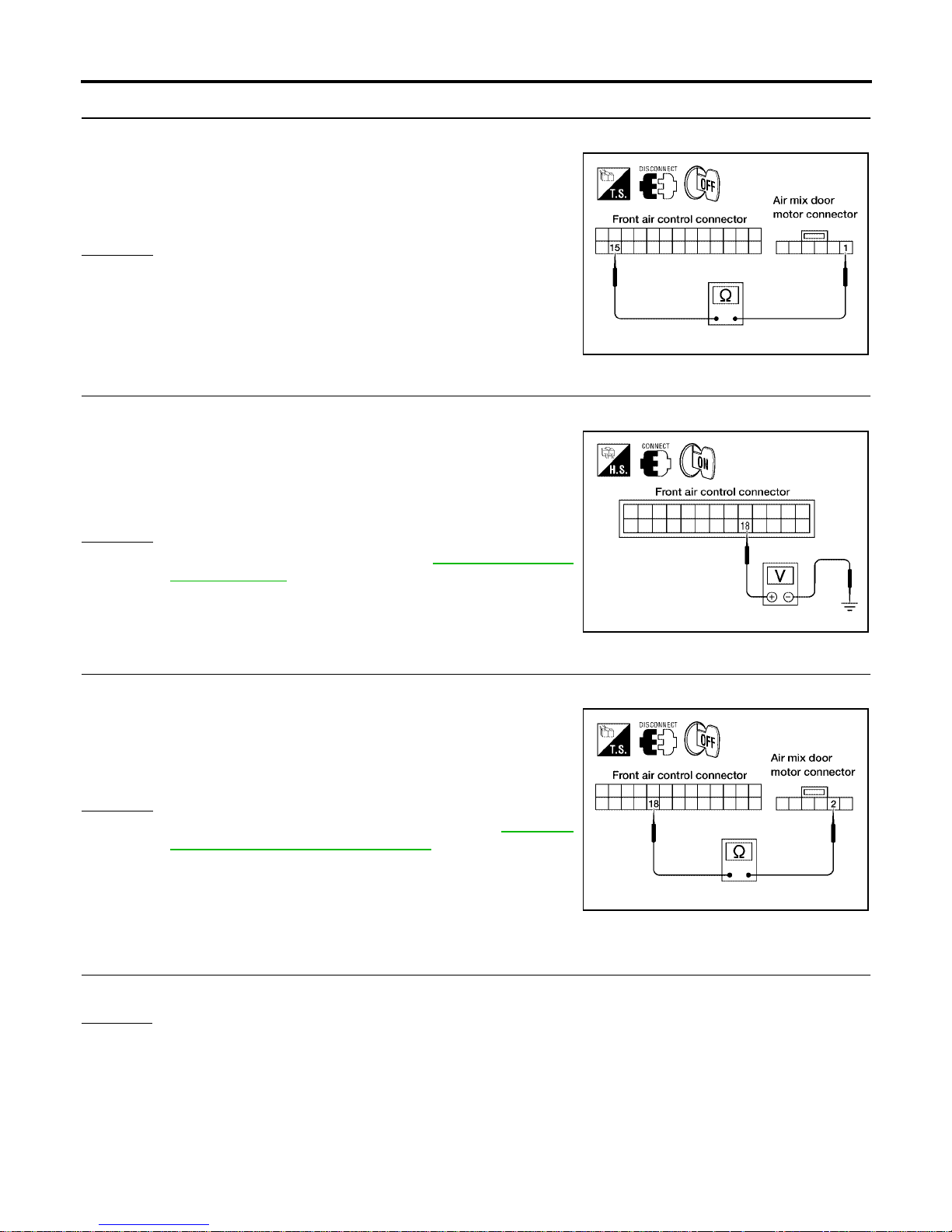
MTC-64
TROUBLE DIAGNOSIS
Revision: January 2005 2004 Quest
5. CHECK PBR GROUND REFERENCE CIRCUIT
1. Disconnect the front air control harness connector.
2. Check continuity between air mix door motor (front) harness
connector M39 te rminal 1 (Y ) and front air control harness c onnector M49 terminal 15 (Y).
OK or NG
OK >> GO TO 6.
NG >> Repair or replace harness as necessary.
6. CHECK PBR FEEDBACK SIGNAL
1. Reconnect the front air cont rol harness connector and air mix door motor (front) harness connector.
2. Check voltage between front air control harness connector M49
terminal 18 (Y/B) and ground.
3. Rotate front temperature dial through complete range.
OK or NG
OK >> Replace front air control. Refer to MTC-116, "FRONT
AIR CONTROL" .
NG >> GO TO 7.
7. CHECK PBR FEEDBACK CIRCUIT
1. Disconnect the air mix door motor (front) harness connector and front air control harness connector.
2. Check continuity between air mix door motor (front) harness
connector M39 terminal 2 (Y/B) and front air control harness
connector M49 terminal 18 (Y/B).
OK or NG
OK >> Replace air mix do or motor (front). Refer to MTC-135,
"AIR MIX DOOR MOTOR (FRONT)" .
NG >> Repair or replace harness as necessary.
DIAGNOSTIC PROCEDURE FOR AIR MIX DOOR MOTOR (REAR)
1. CHECK RESULT FROM FRONT AIR CONTROL SELF-DIAGNOSIS
Self-diagn osis code 38 is present.
Yes or No
Yes > >GO TO 2.
No >> GO TO 3.
Continuity should exist.
WJIA0538E
0V - 5V (Approx.) should exist.
LJIA0041E
Continuity should exist.
WJIA0539E
Page 65
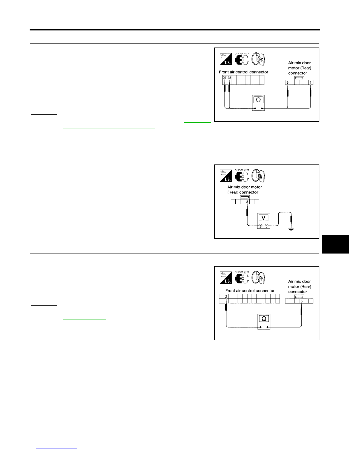
TROUBLE DIAGNOSIS
MTC-65
C
D
E
F
G
H
I
K
L
M
A
B
MTC
Revision: January 2005 2004 Quest
2. CHECK POWER SUPPLY CIRCUIT FOR AIR MIX DOOR MOTOR (REAR)
1. Disconnect front air control connector and air mix door motor
(rear) connector.
2. Check continuity between front air control harness connector
M50 terminal 27 (P/L) and air mix door motor (r ear) connector
B146 terminal 1 ( P/ L) a nd be t wee n f ron t air co ntr ol h arn ess co nnector M50 terminal 28 (LG/R) and air mix door motor (rear)
connector B146 terminal 6 (LG/R).
OK or NG
OK >> Replace air mix door motor (rear). Refer to MTC-136,
"AIR MIX DOOR MOTOR (REAR)" .
NG >> Repair or replace harness as necessary.
3. CHECK PBR REFERENCE SIGNAL VOLTAGE
1. Disconnect the air mix door motor (rear) harness connector.
2. Check voltage between air mix door motor (rear) harness connector B146 term inal 3 (W/G) and ground.
OK or NG
OK >> GO TO 5.
NG >> GO TO 4.
4. CHECK PBR REFERENCE VOLTAGE CIRCUIT BETWEEN MODE DOOR AND FRONT AIR CONTROL
1. Disconnect the front air control harness connector.
2. Check continuity between air mix door motor (rear) harness connector B146 terminal 3 (W/G) and front air control harness connector M49 termi nal 2 (W/G).
OK or NG
OK >> Replace front air control. Refer to MTC-116, "FRONT
AIR CONTROL" .
NG >> Repair or replace harness as necessary.
Continuity should exist.
LJIA0049E
5V (Approx.) should exist.
LJIA0050E
Continuity should exist.
LJIA0051E
Page 66
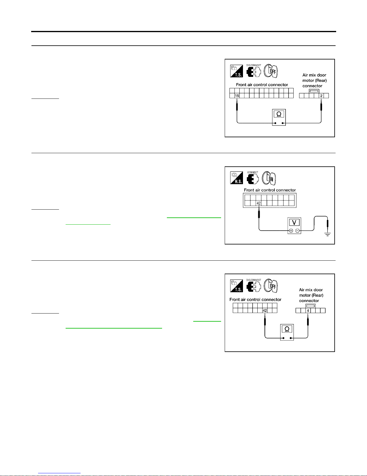
MTC-66
TROUBLE DIAGNOSIS
Revision: January 2005 2004 Quest
5. CHECK PBR GROUND REFERENCE CIRCUIT
1. Disconnect the front air control harness connector.
2. Check continui ty be twee n air mi x door mo tor (rea r) harn ess con nector B146 terminal 2 (Y) and front air control harness connector M49 terminal 15 (Y).
OK or NG
OK >> GO TO 6.
NG >> Repair or replace harness as necessary.
6. CHECK PBR FEEDBACK SIGNAL
1. Reconnect the front air cont rol harness connector and mode door motor conne ctor .
2. Check voltage between front air control harness connector M50
terminal 42 (G/B) and ground.
3. Rotate rear temperatu re dial through complete range .
OK or NG
OK >> Replace front air control. Refer to MTC-116, "FRONT
AIR CONTROL" .
NG >> GO TO 7.
7. CHECK PBR FEEDBACK CIRCUIT
1. Disconnect the air mix door motor (rear) harness connector and front air contr ol harness connector.
2. Check continui ty be twee n air mi x door mo tor (rea r) harn ess con nector B146 terminal 4 (G/B) and front air control harness connector M50 terminal 42 (G/B).
OK or NG
OK >> Replace air mix door motor (rear). Refer to MTC-136,
"AIR MIX DOOR MOTOR (REAR)" .
NG >> Repair or replace harness as necessary.
Continuity should exist.
LJIA0052E
0V - 5V (Approx.) should exist.
LJIA0053E
Continuity should exist.
LJIA0054E
Page 67
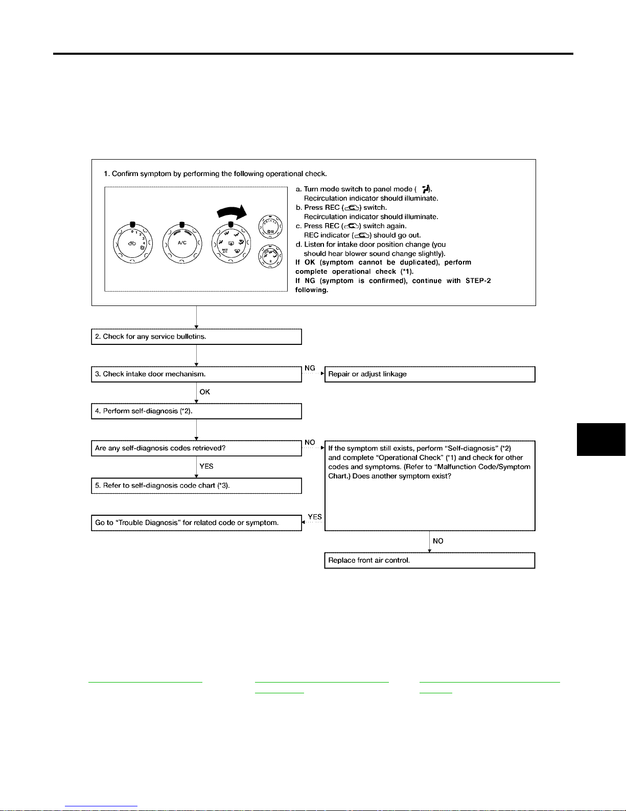
TROUBLE DIAGNOSIS
MTC-67
C
D
E
F
G
H
I
K
L
M
A
B
MTC
Revision: January 2005 2004 Quest
Intake Door Motor Circuit EJ S001SK
SYMPTOM:
● Intake door does not change.
● Intake door motor does not operate normally.
INSPECTION FLOW
*1 MTC-52, "Operational Chec k".*2MTC-50, "A/C System Self-diagno-
sis Function".
*3 MTC-51, "
SELF-DIAGNOSIS CODE
CHART".
WJIA0499E
Page 68
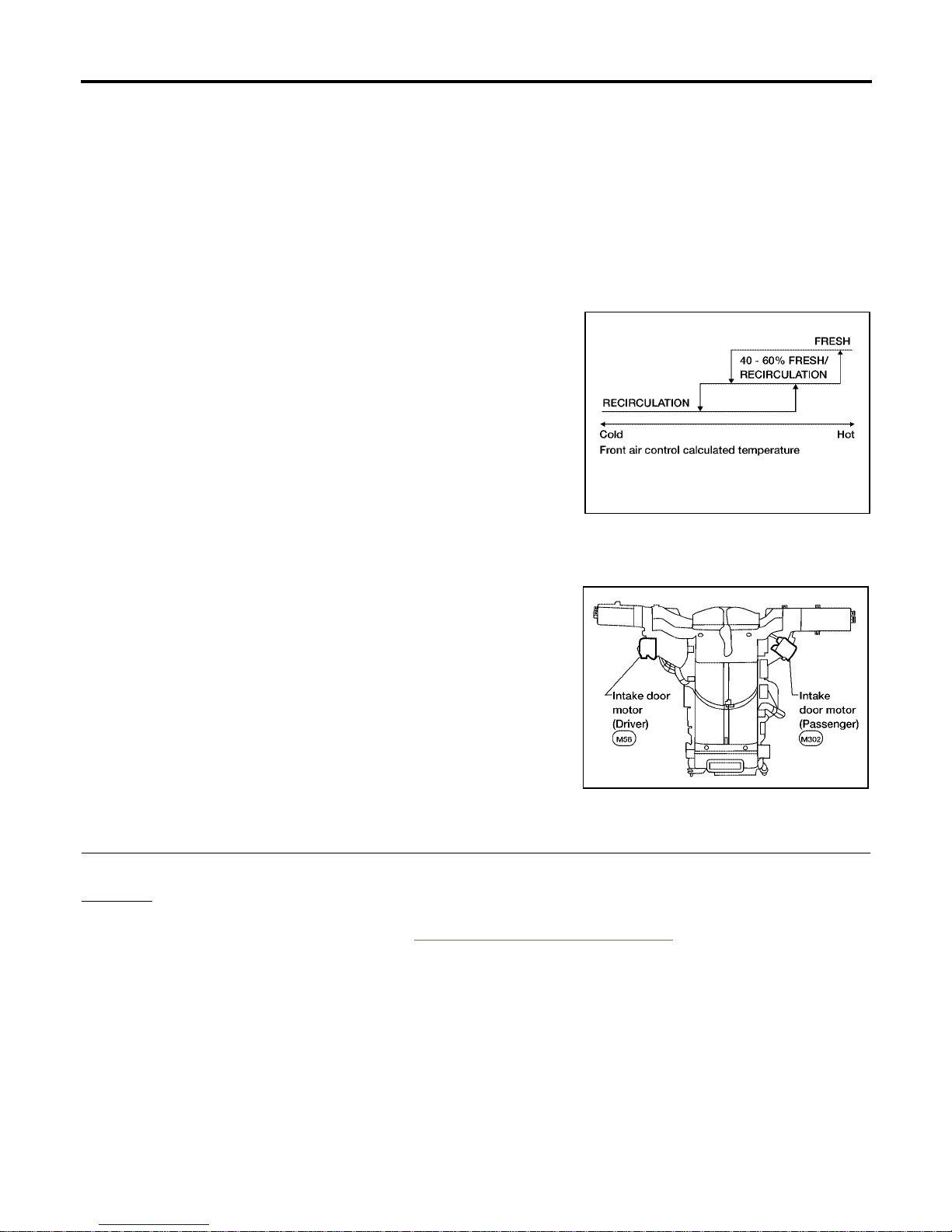
MTC-68
TROUBLE DIAGNOSIS
Revision: January 2005 2004 Quest
SYSTEM DESCRIPTION
Component Parts
Intake door control system components are:
● Front air control
● Intake door motor (driver and passenger)
System Operation
The intake door control determines the intake door (driver and passenger) positions based on the position of
the recirculation switch. When the recirculation swi tch is depressed th e intake door motors ro tate closing off
the fresh air in let an d reci rcula ting t he ca bin a ir. If the recircul ation switc h is d epres sed again , th e intake doo r
motors rotate in the opposite direction, again allowing fresh air into the cabin.
Intake Doors Control Specification
COMPONENT DESCRIPTION
Intake door motors
The driver and passenger intake door motors are attached to the
intake uni t. T hey rot ate so t hat ai r is dra wn fro m inl et s se t by the f ront
air control. Motor rotation is conve yed to a lever which a ctivates the
intake door.
DIAGNOSTIC PROCEDURE FOR INTAKE DOOR MOTOR (DRIVER)
1. CHECK RESULT FROM FRONT AIR CONTROL SELF-DIAGNOSIS
Self-diagn osis code 82 is present.
Yes or No
Yes > >GO TO 2.
No >> Replace front air control. Refer to MT C-116, "
FRONT AIR CONTROL" .
WJIA0436E
WJIA0433E
Page 69
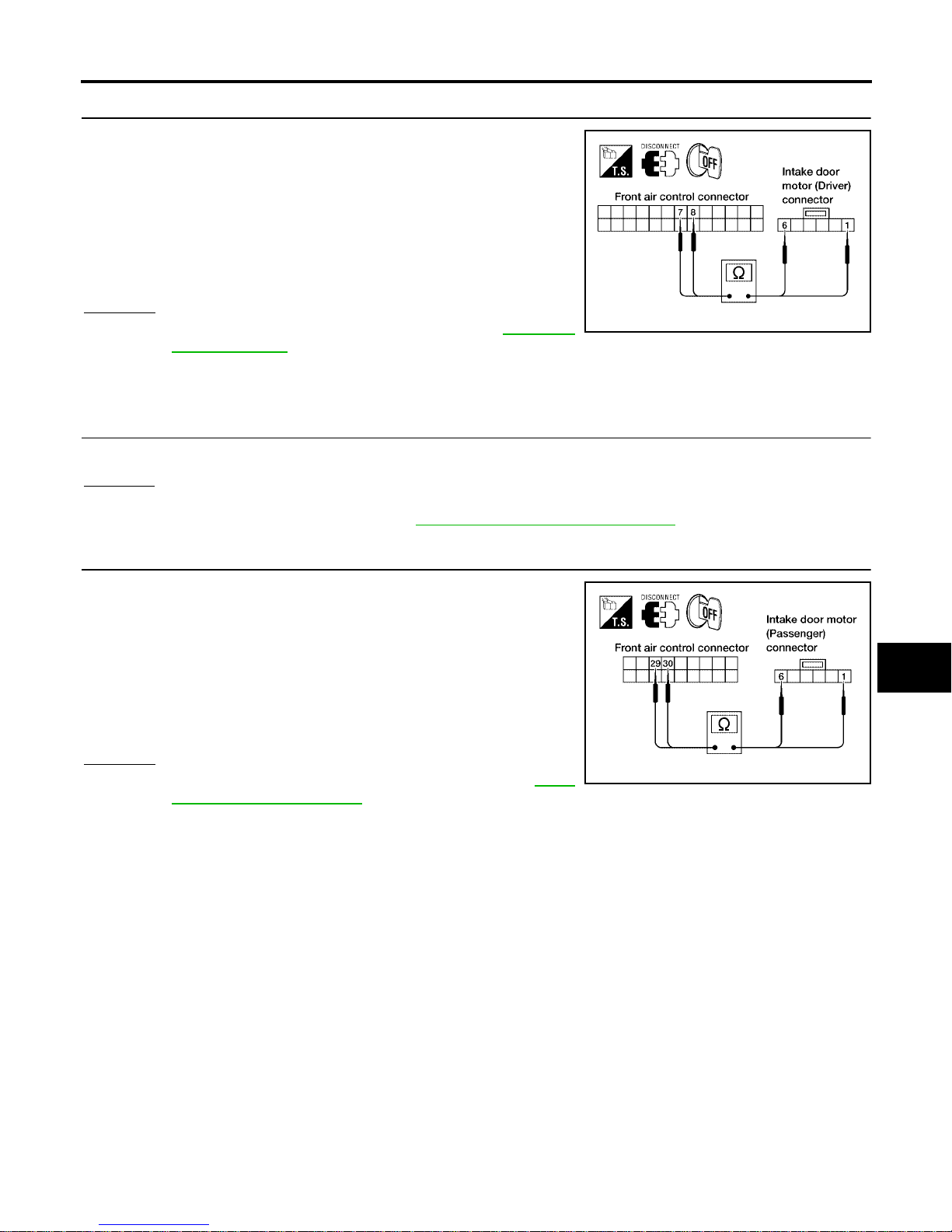
TROUBLE DIAGNOSIS
MTC-69
C
D
E
F
G
H
I
K
L
M
A
B
MTC
Revision: January 2005 2004 Quest
2. CHECK POWER SUPPLY CIRCUIT FOR INTAKE DOOR MOTOR (DRIVER)
1. Disconnect front air control connector and intake door motor
(driver) connector.
2. Check continuity between front air control harness connector
M49 terminal 7 (R/B) and intake do or motor (driver) connector
M58 terminal 1 (R/B) an d b et w ee n fro nt air con tro l ha rn es s c on nector M49 terminal 8 (R) and intake door motor (driver) connector M58 termi nal 6 (R).
OK or NG
OK >> Replace intake door moto r (driver). Refer to MTC-131,
"DRIVER SIDE" .
NG >> Repair or replace harness as necessary.
DIAGNOSTIC PROCEDURE FOR INTAKE DOOR MOTOR (PASSENGER)
1. CHECK RESULT FROM FRONT AIR CONTROL SELF-DIAGNOSIS
Self-diagnosis code 72 is present.
Yes or No
Yes >> GO TO 2 .
No >> Replace front air control. Refer to MTC-116, "
FRONT AIR CONTROL" .
2. CHECK POWER SUPPLY CIRCUIT FOR INTAKE DOOR MOTOR (PASSENGER)
1. Disconnect front air control connector and intake door motor
(passenger ) connector.
2. Check continuity between front air control harness connector
M50 terminal 29 (P /B) and intake door motor (passenger) con nector M302 terminal 1 (P/B) and between front air control harness connector M50 terminal 30 (P) and intake door motor
(passenger ) connector M302 terminal 6 (P) .
OK or NG
OK >> Replace intake door motor (passenger). Refer to MTC-
132, "P A SSENGER SIDE" .
NG >> Repair or replace harness as necessary.
Continuity should exist.
LJIA0060E
Continuity should exist.
LJIA0061E
Page 70
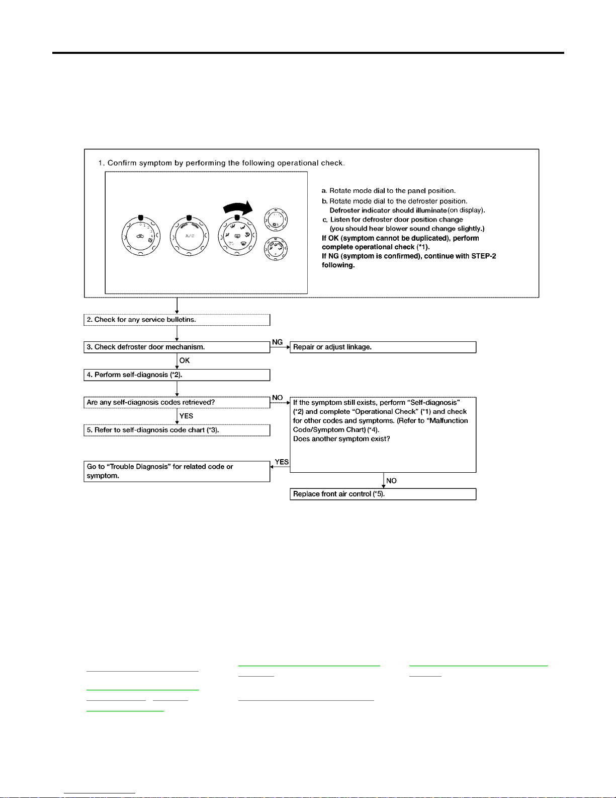
MTC-70
TROUBLE DIAGNOSIS
Revision: January 2005 2004 Quest
Defroster Door Motor Circuit EJS001SL
SYMPTOM:
● Defroster door does not chan ge .
● Defroster door does not operate normally.
INSPECTION FLOW
*1 MTC-52, "Operational Check" *2
MTC-50, "
A/C System Self-diagnosis
Function"
*3
MTC-51, "
SELF-DIAGNOSIS CODE
CHART"
*4
MTC-51, "
SELF-DIAGNOSIS
CODE CHART" / MTC-33,
"SYMPTOM TABLE"
*5 MTC-116, "FRONT AIR CONTROL"
WJIA1614E
Page 71
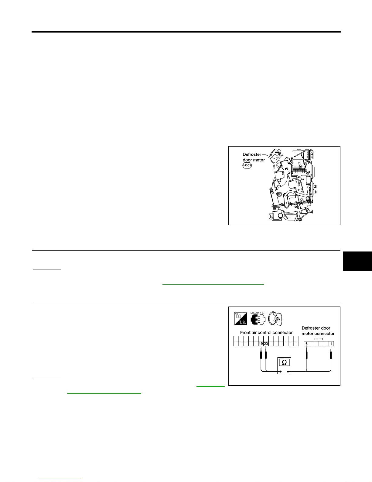
TROUBLE DIAGNOSIS
MTC-71
C
D
E
F
G
H
I
K
L
M
A
B
MTC
Revision: January 2005 2004 Quest
SYSTEM DESCRIPTION
Component Parts
Defroster door control system components are:
● Front air control
● Defroster door motor
System Operation
The front air control determ ines defroster door pos ition based on the posi tion of the mode switch . When the
mode switch is in the defroster position, the defroster door motor rotates directing air to the defroster ducts.
When any mode other than defroster is selected, the defroster motor rotates in the opposite direction closing
off air flow to the defroster ducts.
COMPONENT DESCRIPTION
Defroster door motor
The defroster door motor is attached to the front heater & cooli ng
unit. The front air contro l sends a voltage to rotate to the defroster
door directing th e a ir flow either to th e de fros te r d uc ts, or to the floor
ducts, dependi ng on whic h way the voltage and ground ar e applied
to the motor leads . Motor rotatio n is convey ed to a leve r which activates the defroster door.
DIAGNOSTIC PROCEDURE FOR DEFROSTER DOOR MOTOR
1. CHECK RESULT FROM FRONT AIR CONTROL SELF-DIAGNOSIS
Self-diagnosis code 62 is present.
OK or NG
OK >> GO TO 2.
NG >> Replace front air control. Refer to MTC-116, "
FRONT AIR CONTROL" .
2. CHECK POWER SUPPLY CIRCUITS FOR DEFROSTER DOOR MOTOR
1. Disconnect front air control connector and defroster door motor
connector.
2. Check continuity between front air control harness connector
M49 terminal 19 (W/B) and defroster door motor connector
M303 terminal 1 (W/B) and between front air control harness
connector M49 terminal 20 (W) and defroster door motor connector M303 ter m inal 6 (W).
OK or NG
OK >> Replace defroster door motor. Refer to MTC-129,
"Removal and Installation" .
NG >> Repair or replace harness as necessary.
LJIA0063E
Continuity should exist.
LJIA0064E
Page 72
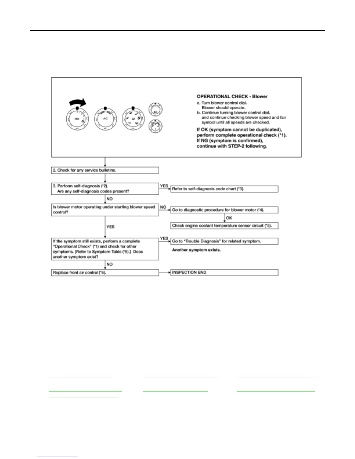
MTC-72
TROUBLE DIAGNOSIS
Revision: January 2005 2004 Quest
Front Blower Motor Circuit EJS001SM
SYMPTOM:
● Blower motor operation is malfunctioning.
INSPECTION FLOW
*1 MTC-52 , " Operational Check".*2MTC-50, "A/C System Self-diagno-
sis Function".
*3 MTC-51, "
SELF-DIAGNOSIS CODE
CHART".
*4 MTC-74 , " DIAGNOSTIC PROCE-
DURE FOR BLOWER MOTOR".
*5 MTC-33, "
SYMPTOM TABLE" *6 MTC-116, "FRONT AIR CONTROL"
WJIA1615E
Page 73
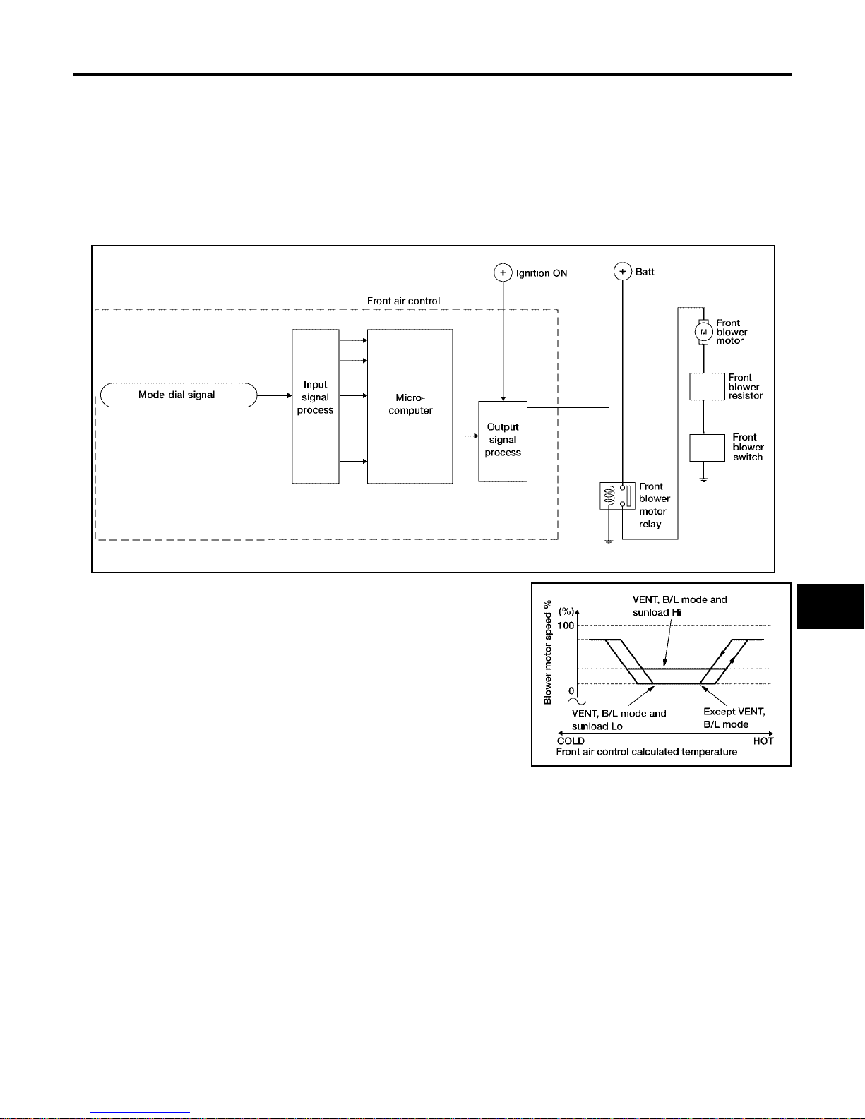
TROUBLE DIAGNOSIS
MTC-73
C
D
E
F
G
H
I
K
L
M
A
B
MTC
Revision: January 2005 2004 Quest
SYSTEM DESCRIPTION
Component Parts
● Front air control
● Front blower switch
● Front blower motor resistor
● Front blower motor
● Front blower motor relay
System Operation
Blower Speed Control Specification
WJIA1616E
WJIA0441E
Page 74
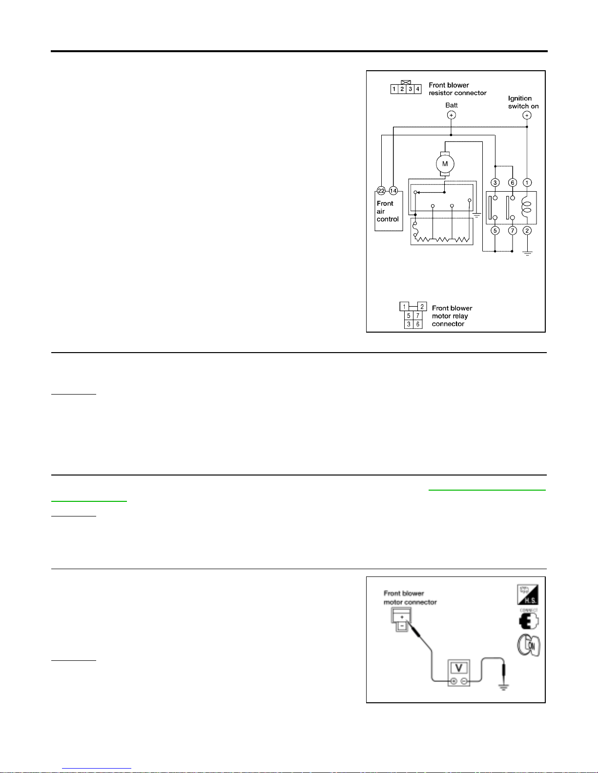
MTC-74
TROUBLE DIAGNOSIS
Revision: January 2005 2004 Quest
DIAGNOSTIC PROCEDURE FOR BLOWER MOTOR
SYMPTOM: Blower motor operation is malfunctioning.
1. DIAGNOSTIC PROCEDURE
Turn the front blower switch to each of its four speeds.
Does blower motor rotate norma ll y at ea ch speed ?
OK or NG
OK >> INSPECTION END.
NG >> 1. Does not rotate at any speed, GO TO 2.
2. Do es not rotate at 1 - 3 speed, G O TO 13.
3. Do es not rotate at 4 spee d, G O TO 16.
2. CHECK FUSES
Check 20A fuses [Nos. 28 and 30, located in the fuse and fusible link box]. Refer to PG-72, "
FUSE AND FUS-
IBLE LINK BOX" .
OK or NG
OK >> GO TO 3.
NG >> GO TO 8.
3. CHECK FRONT BLOWER MOTOR POWER SUPPLY
1. Disconnect front blower motor harness connector.
2. Select any front blower moto r speed except OFF.
3. Check voltage between front blower motor harness connector
M62 terminal + (W/L) and ground.
OK or NG
OK >> GO TO 11.
NG >> GO TO 4.
WJIA0502E
Battery voltage should exist.
WJIA0326E
Page 75
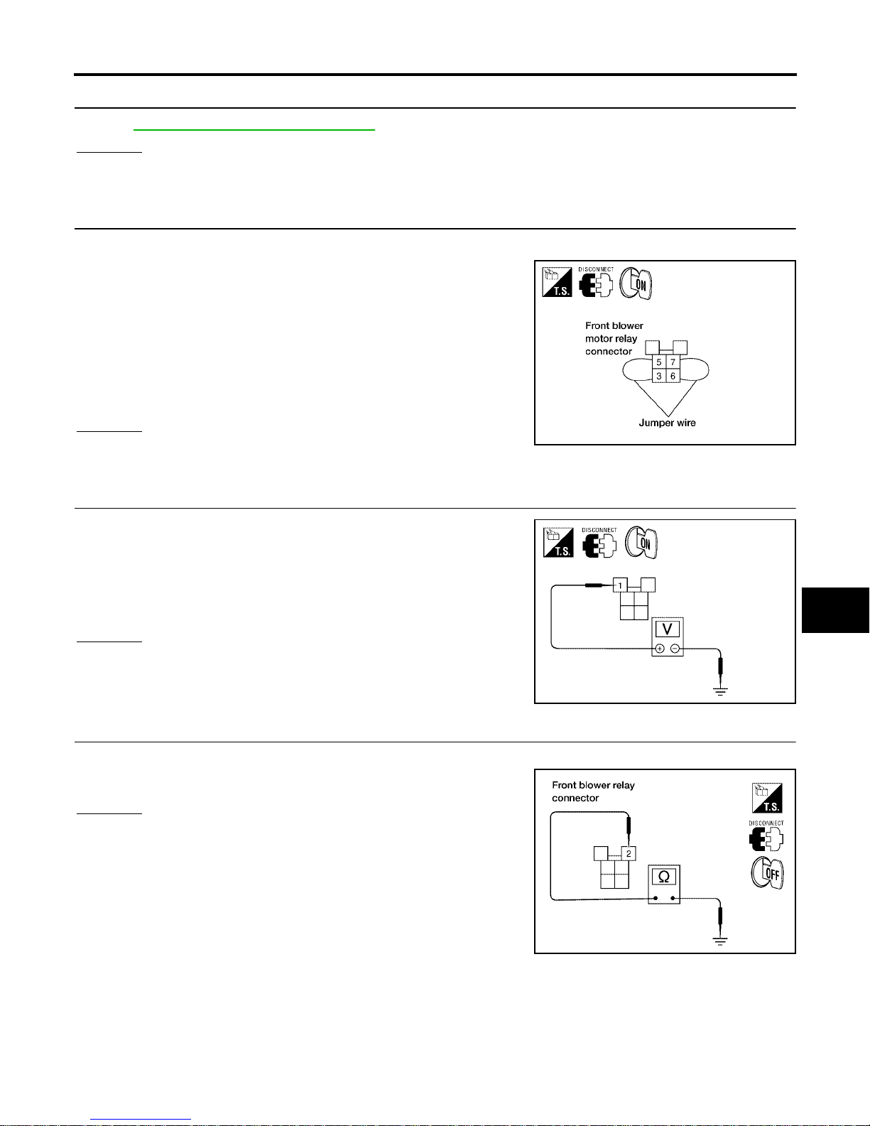
TROUBLE DIAGNOSIS
MTC-75
C
D
E
F
G
H
I
K
L
M
A
B
MTC
Revision: January 2005 2004 Quest
4. CHECK FRONT BLOWER MOTOR RELAY
Refer to MTC-78, "
Front Blower Motor Relay" .
OK or NG
OK >> GO TO 5.
NG >> Replace front blower motor relay.
5. CHECK FRONT BLOWER MOTOR POWER FROM RELAY TO FRONT BLOWER MOTOR
1. Reconnect front blower motor harness connector.
2. Disconnect front blower motor relay.
3. Connect a jumper wire between front blower motor relay connector H2 (har ness side) terminals 3 and 5 and between front
blower motor relay connector H2 (harness side) terminals 6 and
7.
4. Momentarily (no more than 4 seconds), set front blower switch
to any position except OFF.
OK or NG
OK >> GO TO 6.
NG >> GO TO 10.
6. CHECK FRONT BLOWER MOTOR RELAY (COIL SIDE) POWER SUPPL Y CIRCUIT
1. Turn ignition key ON.
2. Set front blower switch to any position except OFF.
3. Check voltage between front blower motor relay harness connector H2 terminal 1 (G/Y) and ground.
OK or NG
OK >> GO TO 7.
NG >> Repair harness or connector.
7. CHECK FRONT BLOWER MOTOR RELAY (COIL SIDE) GROUND CIRCUIT
Check continuity between front blower motor relay harness connector H2 terminal 2 (B) and ground.
OK or NG
OK >> Replace front blower motor relay.
NG >> Repair harness or connector.
Front blower motor should rotate.
WJIA0503E
Battery voltage should exist.
WJIA0504E
Continuity should exist.
WJIA0505E
Page 76
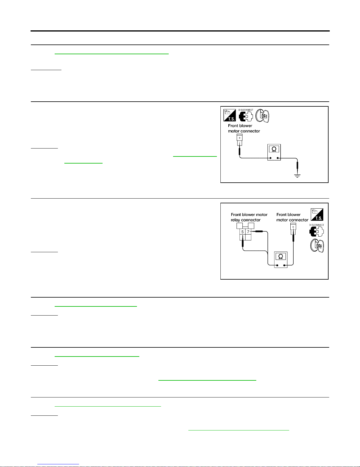
MTC-76
TROUBLE DIAGNOSIS
Revision: January 2005 2004 Quest
8. REPLACE FUSE
Refer to PG-72, "
FUSE AND FUSIBLE LINK BOX" .
Does fuse open when front blower motor is turned on?
YES or NO
YES >> GO TO 9.
NO >> Inspection End .
9. CHECK FRONT BLOWER MOTOR POWER SUPPLY CIRCUIT FOR SHORT
1. Disconnect front blower motor harness connector.
2. Check continuity between front blower motor harness connector
M62 terminal + (W/L) and ground.
OK or NG
OK >> Check front blower motor. Refer to MTC-78, "Front
Blower Motor" .
NG >> Repair harness or connector.
10. CHECK FRONT BLOWER MOTOR RELAY (SWITCH SIDE) POWER SUPPLY CIRCUIT
1. Disconnect front blower motor harness connector.
2. Check contin ui ty be tw ee n f r on t b lower motor relay harn es s c o nnector H2 terminal 5 (W/L) and 7 (W/L) and front blower motor
harness connector M62 terminal + (W/L).
OK or NG
OK >> Repair harness or connector between front blower
motor fuses and front blower motor relay.
NG >> Repair harness or connector between front blower
motor relay and front blower motor.
11. CHECK FRONT BLOWER MOTOR
Refer to MTC-78, "
Front Blower Motor" .
OK or NG
OK >> GO TO 12.
NG >> Replace front blower motor.
12. CHECK FRONT BLOWER SWITCH
Refer to MTC-78, "
Front Blower Switch" .
OK or NG
OK >> Repair harness or connector between front blower switch and front blower motor.
NG >> Replace front air control. Refer to MTC-116, "
FRONT AIR CONTROL" .
13. CHECK FRONT BLOWER MOTOR RESISTOR
Refer to MTC-79, "
Front Blower Motor Resistor" .
OK or NG
OK >> GO TO 14.
NG >> Replace fron t blower motor resistor. Refer to MTC-137, "
Removal and Installation" .
Continuity should not exist.
WJIA0506E
Continuity should exist.
WJIA0968E
Page 77
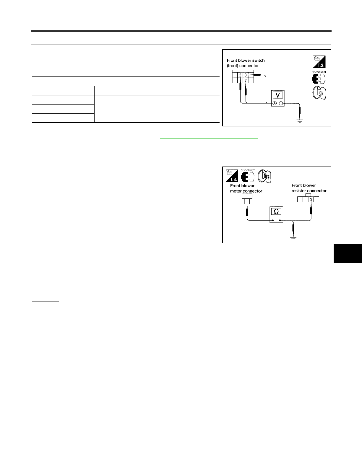
TROUBLE DIAGNOSIS
MTC-77
C
D
E
F
G
H
I
K
L
M
A
B
MTC
Revision: January 2005 2004 Quest
14. CHECK FRONT BLOWER SWITCH CIRCUIT
1. Reconnect front blower motor resi stor harness connector.
2. Check voltage between front blower s witch connector M51 te rminals 2 (G/B), 3 (L/Y), and 7 (L/R) and ground.
OK or NG
OK >> Replace front air control. Refer to MTC-116, "FRONT AIR CONTROL" .
NG >> GO TO 15.
15. CHECK FRONT BLOWER MOTOR GROUND CIRCUIT TO FRONT BLOWER MOTOR RESISTOR
1. Disconnect front blower motor and front blower motor resistor
harness connector.
2. Check continuity between front blower motor connector M62 terminal - (L/W) and front blower moto r resistor ha rness conn ector
M122 terminal 3 (L/W).
3. Check continuity between front blower motor connector M62 terminal - (L/W) and ground.
OK or NG
OK >> INSPECTION END.
NG >> Repair harness or connector.
16. CHECK FRONT BLOWER SWITCH
Refer to MTC-78, "
Front Blower Switch" .
OK or NG
OK >> Repair harness or connector.
NG >> Replace front air control. Refer to MTC-116, "
FRONT AIR CONTROL" .
Terminal No.
Voltage
(Approx.)
+2
Ground 12V3
7
WJIA0969E
Continuity should exist.
Continuity should not exist.
WJIA0970E
Page 78
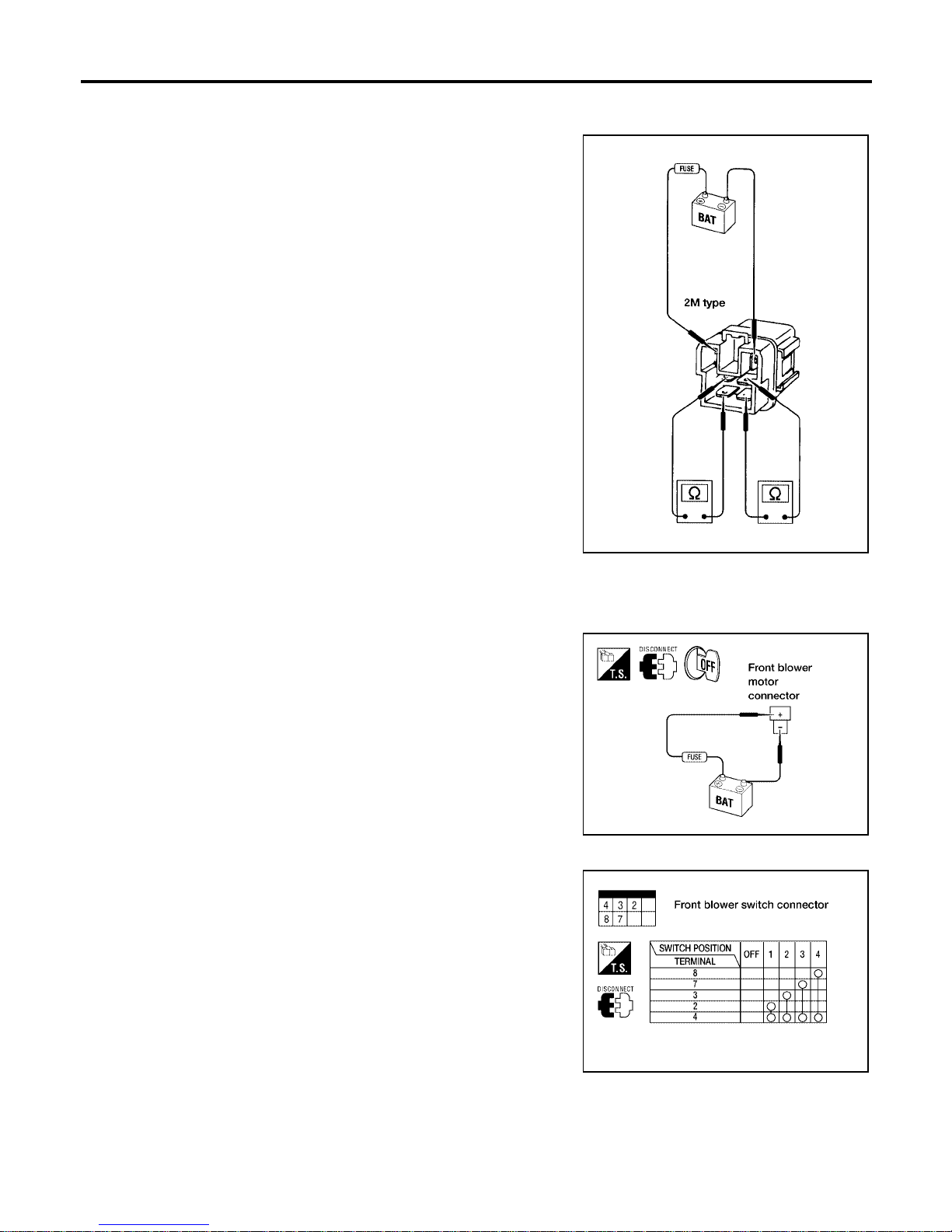
MTC-78
TROUBLE DIAGNOSIS
Revision: January 2005 2004 Quest
COMPONENT INSPECTION
Front Blower Motor Relay
Check continu ity between terminals 6 an d 7 and terminals 3 and 5
after supplying 12 volts to terminal 1 and ground to terminal 2 of
relay.
Front Blower Motor
Confirm smooth rotation of the blower motor.
● Ensure that there are no foreign particles inside the blower unit.
● Apply 12 volts to terminal + and ground to term inal - and verify
that the motor operates free ly and quietly .
Front Blower Switch
Check continuit y be tw ee n term in als at each switch posi tio n.
LJIA0068E
LJIA0081E
WJIA0508E
Page 79
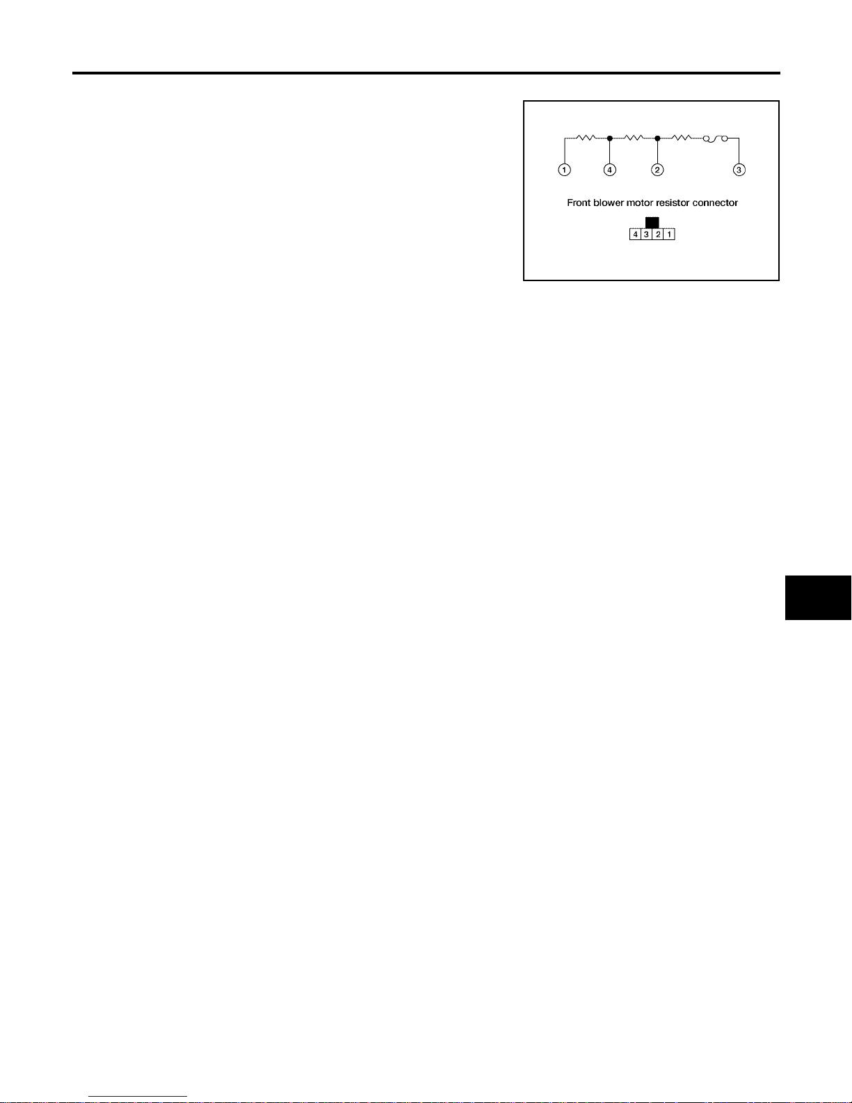
TROUBLE DIAGNOSIS
MTC-79
C
D
E
F
G
H
I
K
L
M
A
B
MTC
Revision: January 2005 2004 Quest
Front Blower Motor Resistor
Check continuity between terminals. There will be resistance, but
there should not be an open or short between any two terminals.
WJIA0971E
Page 80
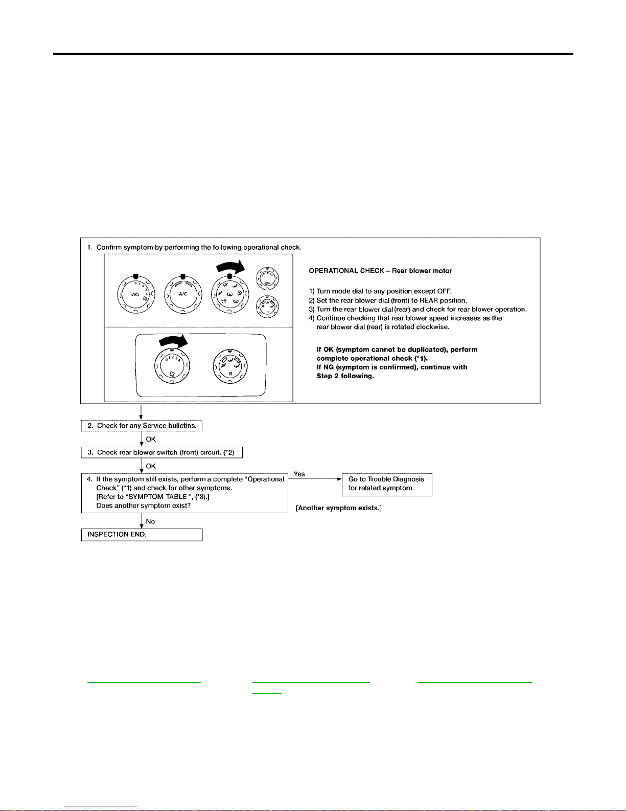
MTC-80
TROUBLE DIAGNOSIS
Revision: January 2005 2004 Quest
Rear Blower Motor Circuit EJS001SN
SYMPTOM:
● Blower motor operation is malfunctioning.
INSPECTION FLOW
*1 MTC-52, "Operational Check" *2 MTC-89, "Rear Blower Switch
(Front)"
*3 MTC-33, "SYMPTOM TABLE"
WJIA1617E
Page 81
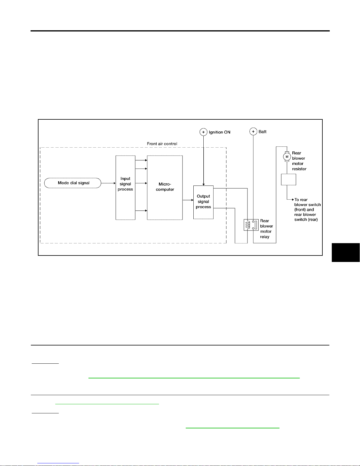
TROUBLE DIAGNOSIS
MTC-81
C
D
E
F
G
H
I
K
L
M
A
B
MTC
Revision: January 2005 2004 Quest
SYSTEM DESCRIPTION
Component Parts
Rear blower speed control system components are:
● Front air control
● Rear blower switch (front)
● Rear blower switch (rear)
● Rear blower motor resistor
● Rear blower motor
● Rear blower motor relay
System Operation
Rear Blower Control
When the rear blower switch (front) is in the OFF position, the rear blower motor cannot operate.
When the rear blow er switch (front) is in the RE AR position, it al lows the rear b lower switch (re ar) to control
the rear blower motor speed. In any other position (1-4) , the rear blower switch (front) controls the rear blower
motor speed regardless of the rear blower swi tch (rear) posi tio n.
DIAGNOSTIC PROCEDURE FOR REAR BLOWER MOTOR
Rear Blower Switch (Rear) Circuit
SYMPTOM:
● Rear blower motor does not rotate when rear blower switch (front) is set to REAR position.
1. CHECK REAR BLOWER MOTOR OPERATION
Blower motor r otates normally when rear blower switch (front) is set at 1 - 4 sp eed.
OK or NG
OK >> GO TO 2.
NG >> Refer to MTC-83, "
Trouble Diagnosis Procedure For Rear Blower Motor (1 - 4 Speed)" .
2. CHECK REAR BLOWER SWITCH (FRONT)
Refer to MTC-89, "
Rear Blower Switch (Front)" .
OK or NG
OK >> GO TO 3.
NG >> Replace rear blower switch (f ront). Refer to MTC-116, "
REAR AIR CONTROL" .
WJIA1618E
Page 82
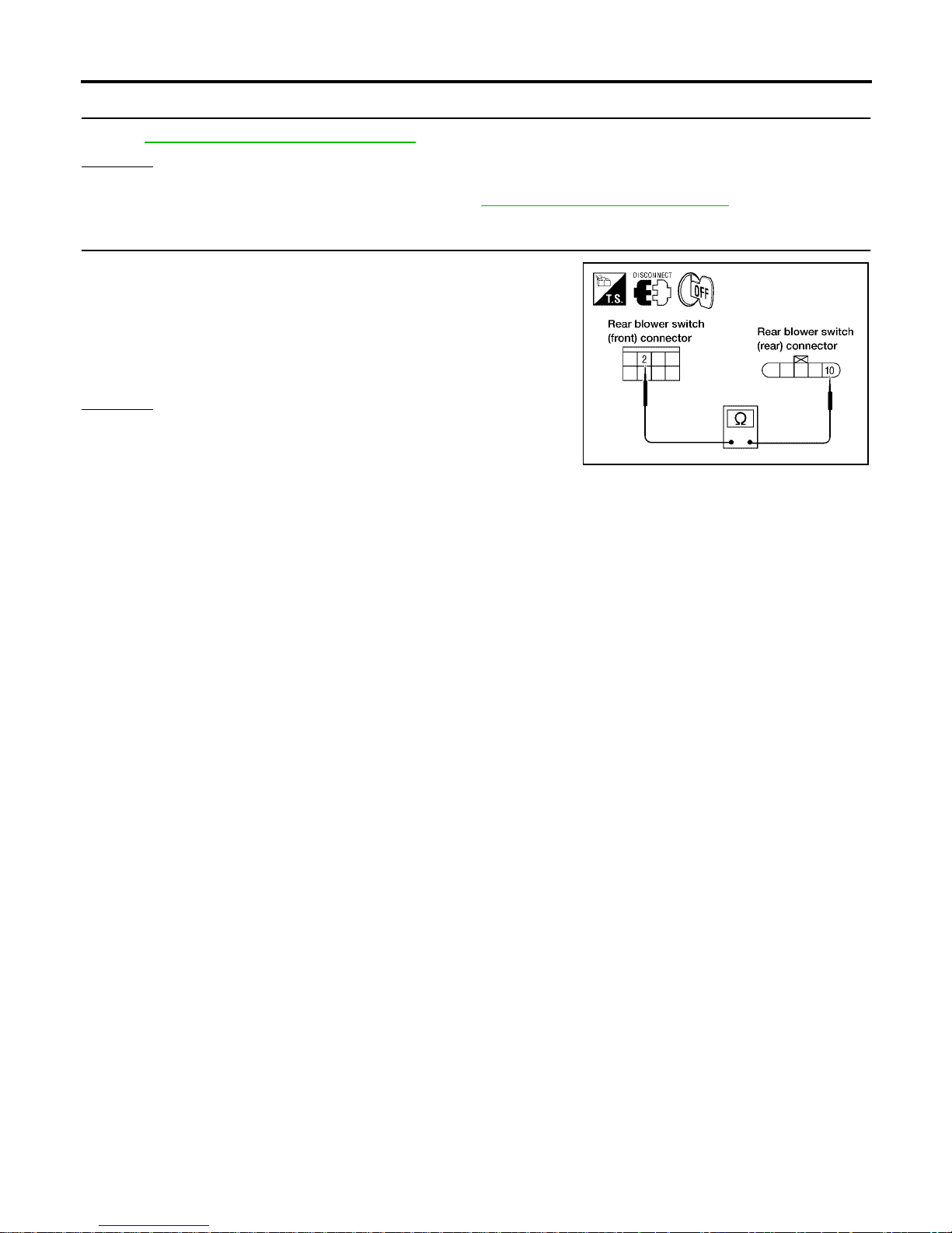
MTC-82
TROUBLE DIAGNOSIS
Revision: January 2005 2004 Quest
3. CHECK REAR BLOWER SWITCH (REAR)
Refer to MTC-89, "
Rear Blower Switch (Rear)" .
OK or NG
OK >> GO TO 4.
NG >> Replace rear blower switch (rear). Refer to MTC-116, "
REAR AIR CONTROL" .
4. CHECK CIRCUIT CONTINUITY
1. Disconnect rear blower switch (front) harness connector and
rear blower switch (rear) harness connector.
2. Check continuity between rear blower switch (front) harness
connector M52 terminal 2 (W) a nd rea r bl owe r swi tch (rea r) h arness connector B141 terminal 10 (W).
OK or NG
OK >> Inspection End.
NG >> Repair harness or connector.
Continuity should exist.
LJIA0098E
Page 83
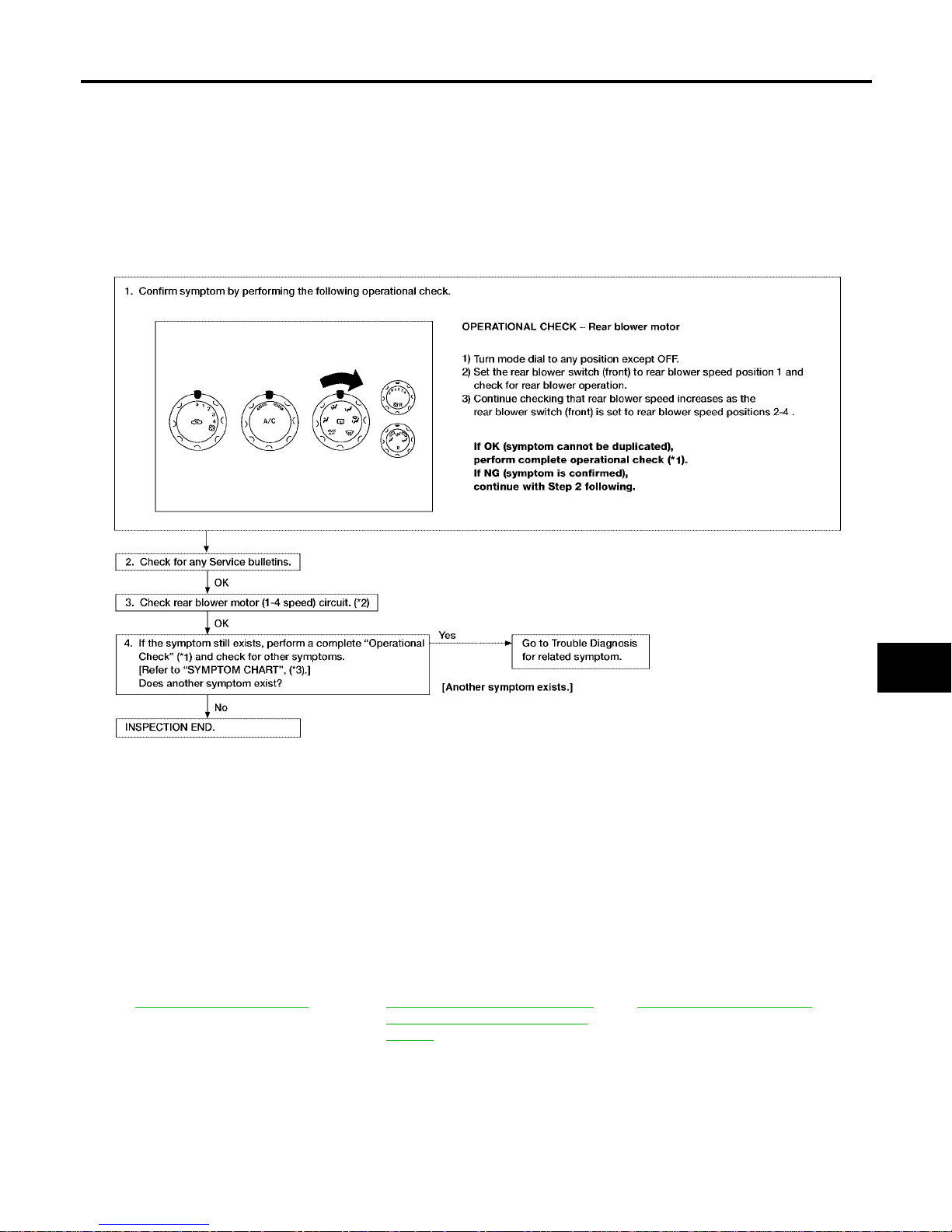
TROUBLE DIAGNOSIS
MTC-83
C
D
E
F
G
H
I
K
L
M
A
B
MTC
Revision: January 2005 2004 Quest
Trouble Diagnosis Procedure For Rear Blower Motor (1 - 4 Speed)
SYMPTOM:
● Rear blower motor does not rotate when rear blower switch (front) is set at 1 - 4 speed.
Inspection Flow
*1 MTC-52, "Operational Check" *2 MTC-83, "Trouble Diagnosis Proce-
dure For Rear Blower Motor (1 - 4
Speed)"
*3 MTC-33, "SYMPTOM TA BLE"
WJIA1620E
Page 84
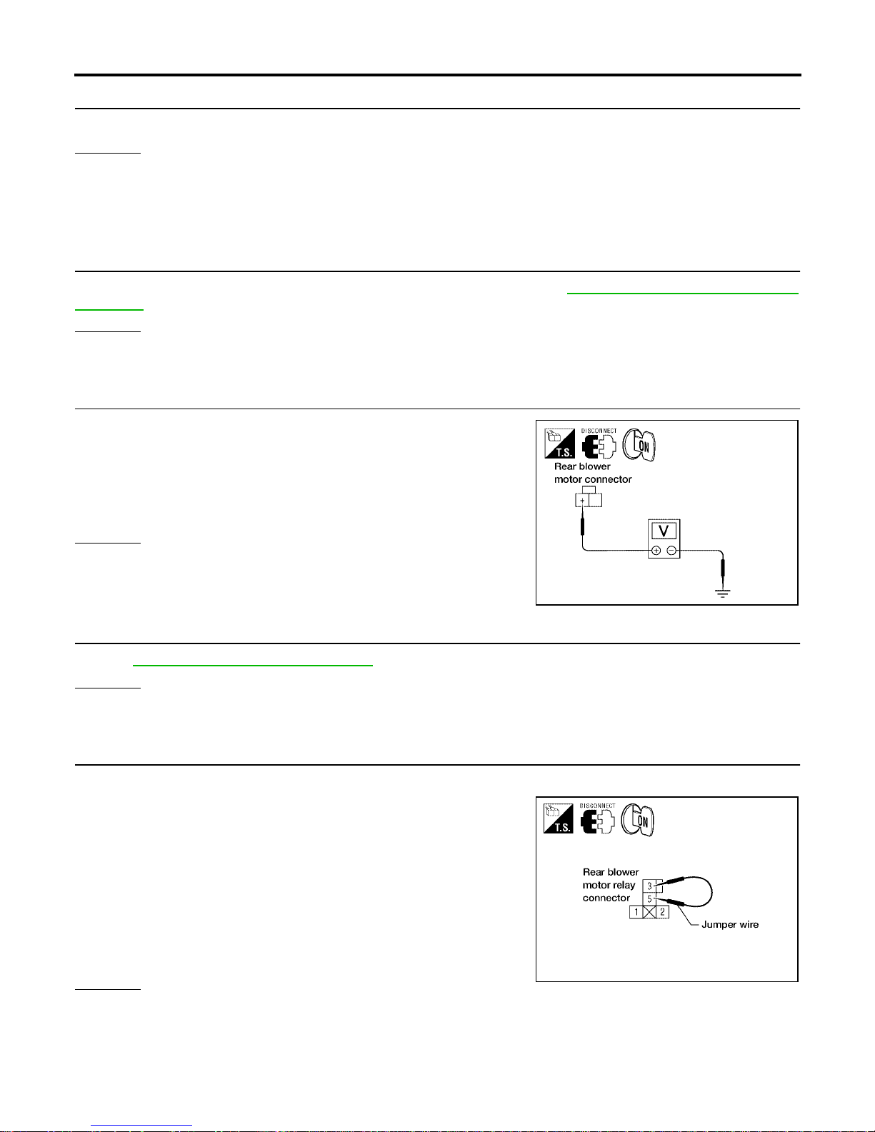
MTC-84
TROUBLE DIAGNOSIS
Revision: January 2005 2004 Quest
1. DIAGNOSTIC PROCEDURE
Blower motor rotates normally at each speed.
OK or NG
OK >> Inspection End.
NG >> 1. Does not rotate at any speed, GO TO 2.
2. Do es not rotate at 1 - 3 speed, G O TO 13.
3. Do es not rotate at 4 spee d, G O TO 18.
2. CHECK FUSES
Check 15A fuses [Nos. 10 and 1 1, located in the fuse block (J/B)]. Refer to PG-71, "
FUSE BLOCK-JUNCTION
BOX(J/B)" .
OK or NG
OK >> GO TO 3.
NG >> GO TO 8.
3. CHECK REAR BLOWER MOTOR POWER SUPPLY
1. Disconnect rear blower mot or harness connector.
2. Select any rear blower speed except OFF.
3. Check voltage between rear blower motor harness connector
B134 termin al + (L/R) and ground.
OK or NG
OK >> GO TO 11.
NG >> GO TO 4.
4. CHECK REAR BLOWER MOTOR RELAY
Refer to MTC-89, "
Rear Blower Motor Relay" .
OK or NG
OK >> GO TO 5.
NG >> Replace rear blower motor relay.
5. CHECK REAR BLOWER MOTOR POWER FROM RELAY TO REAR BLOWER MOTOR
1. Reconnect rear blower motor harness connector.
2. Disconnect rear blower mot or relay.
3. Turn ig nit ion sw itch O N and sel ect any rear b lower speed ex cept
OFF.
4. Set rear blower switch (front) to any position except OFF , REAR,
or 4 - speed.
5. Momentarily (no m ore than 4 seconds), connect a jum per wire
between rear blower motor relay connector J1 (harness side)
terminals 3 and 5.
OK or NG
OK >> GO TO 6.
NG >> GO TO 10.
Battery voltage should exist.
LJIA0099E
Rear blower motor should rotate.
WJIA0972E
Page 85
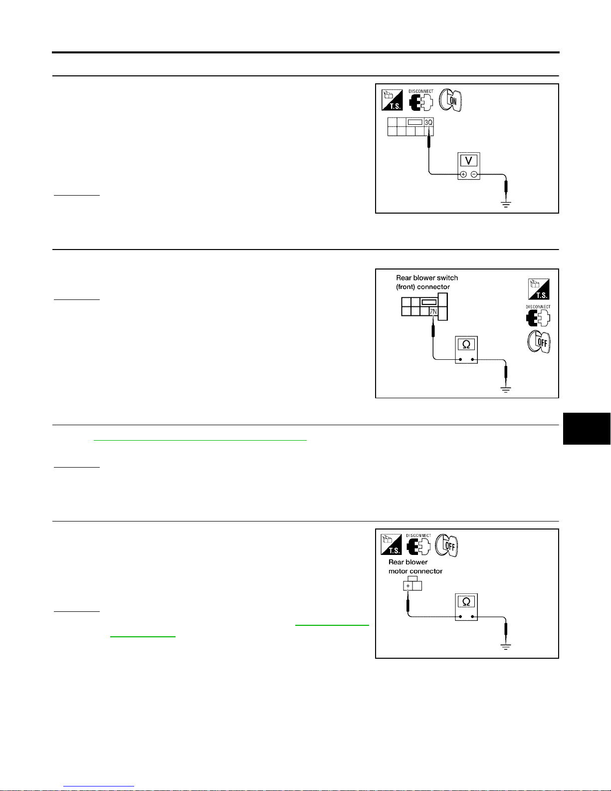
TROUBLE DIAGNOSIS
MTC-85
C
D
E
F
G
H
I
K
L
M
A
B
MTC
Revision: January 2005 2004 Quest
6. CHECK REAR BLOWER MOTOR RELAY (COIL SIDE) POWER SUPPL Y CIRCUIT
1. Disconnect fuse block (J/B) harness connector.
2. Turn ignition switch ON.
3. Set rear blowe r s wit ch ( f ron t ) t o any po si t ion ex ce pt OFF, REAR,
or 4 - speed.
4. Check voltage betw een fuse bloc k (J/B) h ar ness c onne ctor E30
terminal 3Q (W/G) and ground.
OK or NG
OK >> GO TO 7.
NG >> GO TO 20.
7. CHECK REAR BLOWER MOTOR RELAY (COIL SIDE) GROUND CIRCUIT
Check contin uity between fuse block (J/B) harness connec tor M3 terminal 7N (B) and ground .
OK or NG
OK >> Replace fuse block (J/B).
NG >> Repair harness or connector.
8. REPLACE FUSE
Refer to PG-71, "
FUSE BLOCK-JUNCTION BOX(J/B)"
Fuse should not open when rear blower motor is activated.
OK or NG
OK >> Inspection End.
NG >> GO TO 9.
9. CHECK REAR BLOWER MOTOR POWER SUPPLY CIRCUIT FOR SHORT
1. Disconnect battery cables and rear bl ower motor harness connector.
2. Check continuity between rear blower motor harness connector
B134 terminal + (L/R) and grou nd.
OK or NG
OK >> Check rear blower motor. Refer to MTC-90, "Rear
Blower Motor" .
NG >> Repair harness or connector.
Battery voltage should exist.
LJIA0101E
Continuity should exist.
LJIA0102E
Continuity should not exist.
LJIA0104E
Page 86
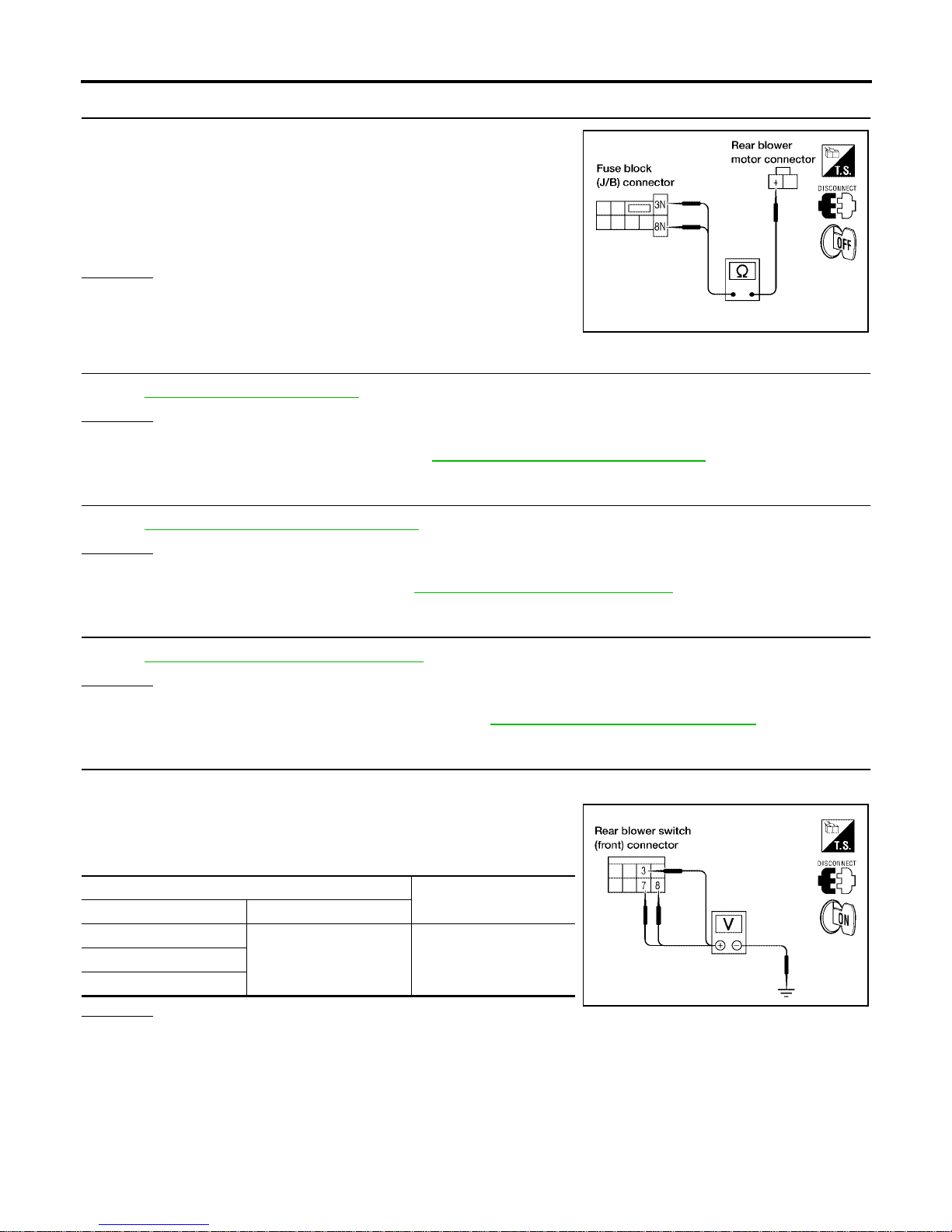
MTC-86
TROUBLE DIAGNOSIS
Revision: January 2005 2004 Quest
10. CHECK REAR BLOWER MOTOR RELAY (SWITCH SIDE) POWER SUPPLY CIRCUIT
1. Disconnect fuse block (J/B) and rear blower motor harness connectors.
2. Check continuity between fuse block (J/B) harness connector
M3 terminal 3N (L/R) and 8N (L/R) and rear blower motor harness connector B134 terminal + (L/R).
OK or NG
OK >> GO TO 20.
NG >> Repair harness or connector.
11. CHECK REAR BLOWER MOTOR
Refer to MTC-90, "
Rear Blower Motor" .
OK or NG
OK >> GO TO 12.
NG >> Replace rear blower motor. Refer to MTC-120, "
REAR BLOWER MOTOR" .
12. CHECK REAR BLOWER SWITCH (FRONT)
Refer to MTC-89, "
Rear Blower Switch (Front)" .
OK or NG
OK >> GO TO 15.
NG >> Replace front air control. Refer to MTC-116, "
FRONT AIR CONTROL" .
13. CHECK REAR BLOWER MOTOR RESISTOR
Refer to MTC-90, "
Rear Blower Motor Resist o r" .
OK or NG
OK >> GO TO 14.
NG >> Replace rear blower motor resist or. Refer to MTC-138, "
Removal and Installation" .
14. CHECK REAR BLOWER SWITCH (FRONT) CIRCUIT
1. Disconnect rear blower switch (front).
2. Reconnect rear blower motor resistor harness connector.
3. Check voltage between e ach rear b lower swit ch (front) co nnector M52 terminals 3 (LG), 7 (LG/B), and 8 (G), and ground.
OK or NG
OK >> GO TO 17.
NG >> GO TO 16.
Continuity should exist.
LJIA0107E
Terminal No.
Voltage
(Approx.)
+3
Ground 12V7
8
LJIA0108E
Page 87
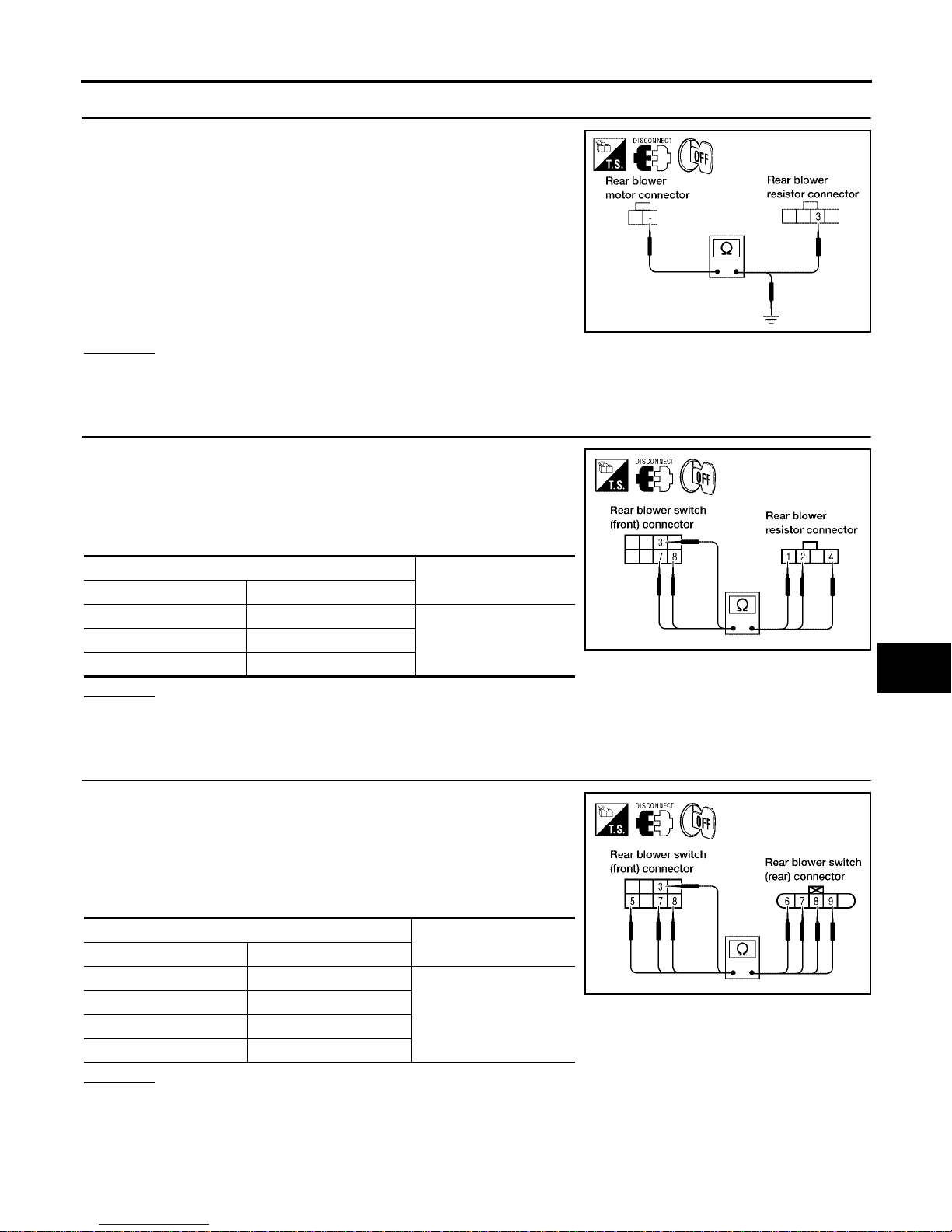
TROUBLE DIAGNOSIS
MTC-87
C
D
E
F
G
H
I
K
L
M
A
B
MTC
Revision: January 2005 2004 Quest
15. CHECK REAR BLOWER MOTOR GROUND CIRCUIT TO REAR BLOWER MOTOR RESISTOR
1. Disconnect rear blower motor and rear blower motor resistor
harness connector.
2. Check continuity between rear blower motor connector B134
terminal - (L/B) and re ar blower mo tor resistor h arness connec tor B133 terminal 3 (L/B).
3. Check continuity between rear blower motor connector B134
terminal - (L/B) and ground.
OK or NG
OK >> GO TO 16.
NG >> Repair harness or connector.
16. CHECK REAR BLOWER SWITCH (FRONT) CIRCUIT
1. Disconnect rear blower resistor h arness connecto r.
2. Check continuity between rear blower switch (front) connector
M52 terminals 3 (LG), 7 (LG/B), and 8 (G), and rear blower
motor resistor connector B133 terminals 1 (LG), 4 (LG/B), and 2
(G).
OK or NG
OK >> Inspection End.
NG >> Repair harness or connector.
17. CHECK REAR BLOWER SWITCH (FRONT) CIRCUIT
1. Disconnect rear blower resistor and rear blower switch (rear)
harness connectors.
2. Check continuity between rear blower switch (front) connector
M52 terminals 3 (LG), 5 (L/B), 7 (LG/B), and 8 (G), and rear
blower switch (rear) co nnecto r B141 te rminals 9 (LG), 6 (L/B), 8
(LG/B), and 7 (G).
OK or NG
OK >> GO TO 18.
NG >> Repair harness or connector.
Continuity should exist.
Continuity should not exist.
LJIA0118E
Terminal No.
Continuity
Rear blower switch (front) Rear blower motor resistor
31
Should exist74
82
LJIA0109E
Terminal No.
Continuity
Rear blower switch (front) Rear blower switch (rear)
39
Should exist
56
78
87
LJIA0110E
Page 88
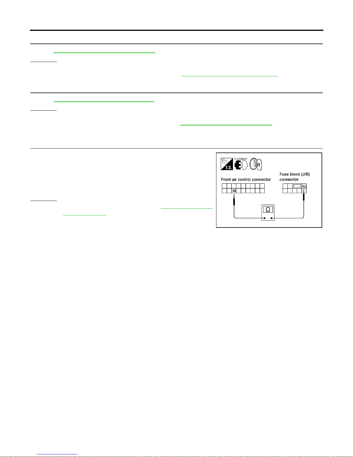
MTC-88
TROUBLE DIAGNOSIS
Revision: January 2005 2004 Quest
18. CHECK REAR BLOWER SWITCH (FRONT)
Refer to MTC-89, "
Rear Blower Switch (Front)" .
OK or NG
OK >> GO TO 19.
NG >> Replace rear blower switch (front). Refer to MTC-116, "
FRONT AIR CONTROL" .
19. CHECK REAR BLOWER SWITCH (REAR)
Refer to MTC-89, "
Rear Blower Switch (Rear)" .
OK or NG
OK >> INSPECTION END.
NG >> Replace rear blower switch (rear). Refer to MTC-116, "
REAR AIR CONTROL" .
20. CHECK CIRCUIT BETWEEN FRONT AIR CONTROL AND FUSE BLOCK (J/B) [REAR BLOWER
MOTOR RELAY (COIL SIDE) POWER]
1. Disconnect fr ont air control and fuse block (J/B) connectors .
2. Check continuity between front air control harness connector
M50 terminal 38 (W/G) and fuse block (J/B) connector E30 terminal 3Q (W/G).
OK or NG
OK >> Replace front ai r control. Refer to MTC-116, "FRONT
AIR CONTROL" .
NG >> Repair harness or connector.
Continuity should exist.
LJIA0111E
Page 89
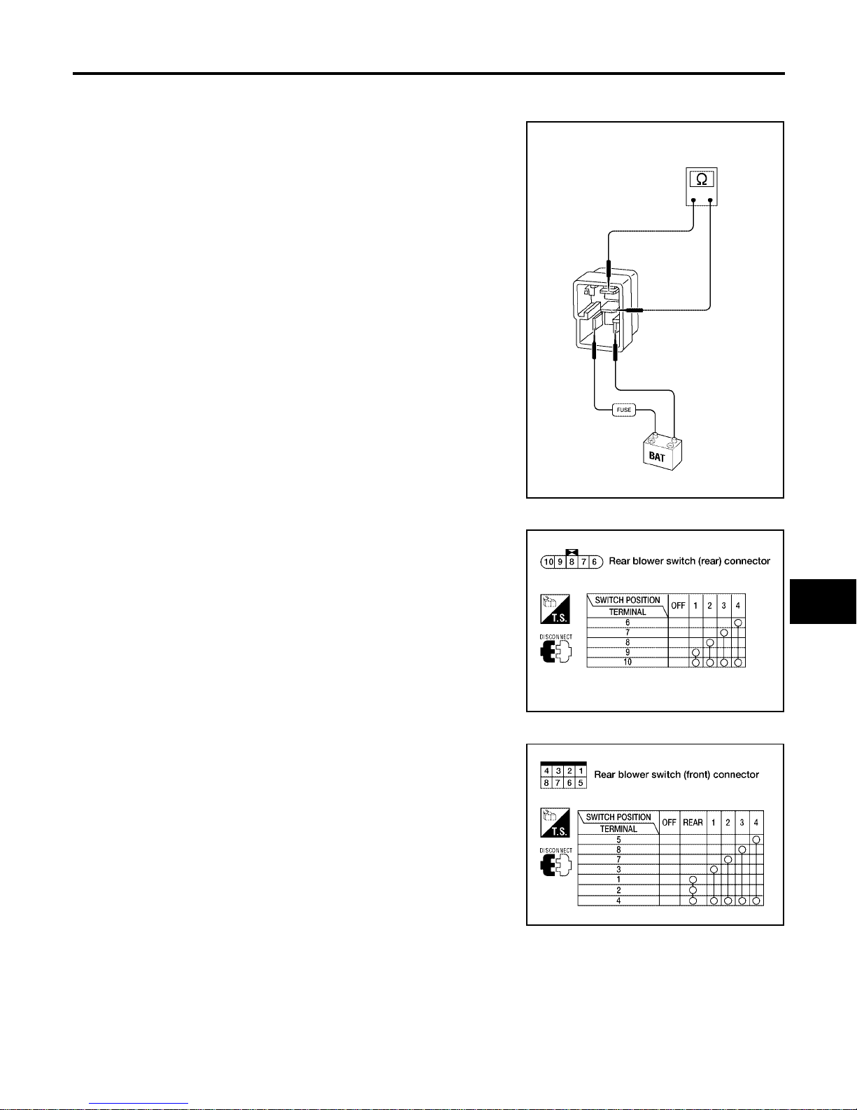
TROUBLE DIAGNOSIS
MTC-89
C
D
E
F
G
H
I
K
L
M
A
B
MTC
Revision: January 2005 2004 Quest
COMPONENT INSPECTION
Rear Blower Motor Relay
Check circuit continuity between terminals by supplying 12 volts and
ground to coil side terminals of relays.
Rear Blower Switch (Rear)
Check continuity between terminals at each switch position.
Rear Blower Switch (Front)
Check continuity between terminals at each switch position.
WJIA0973E
LJIA0113E
LJIA0114E
Page 90
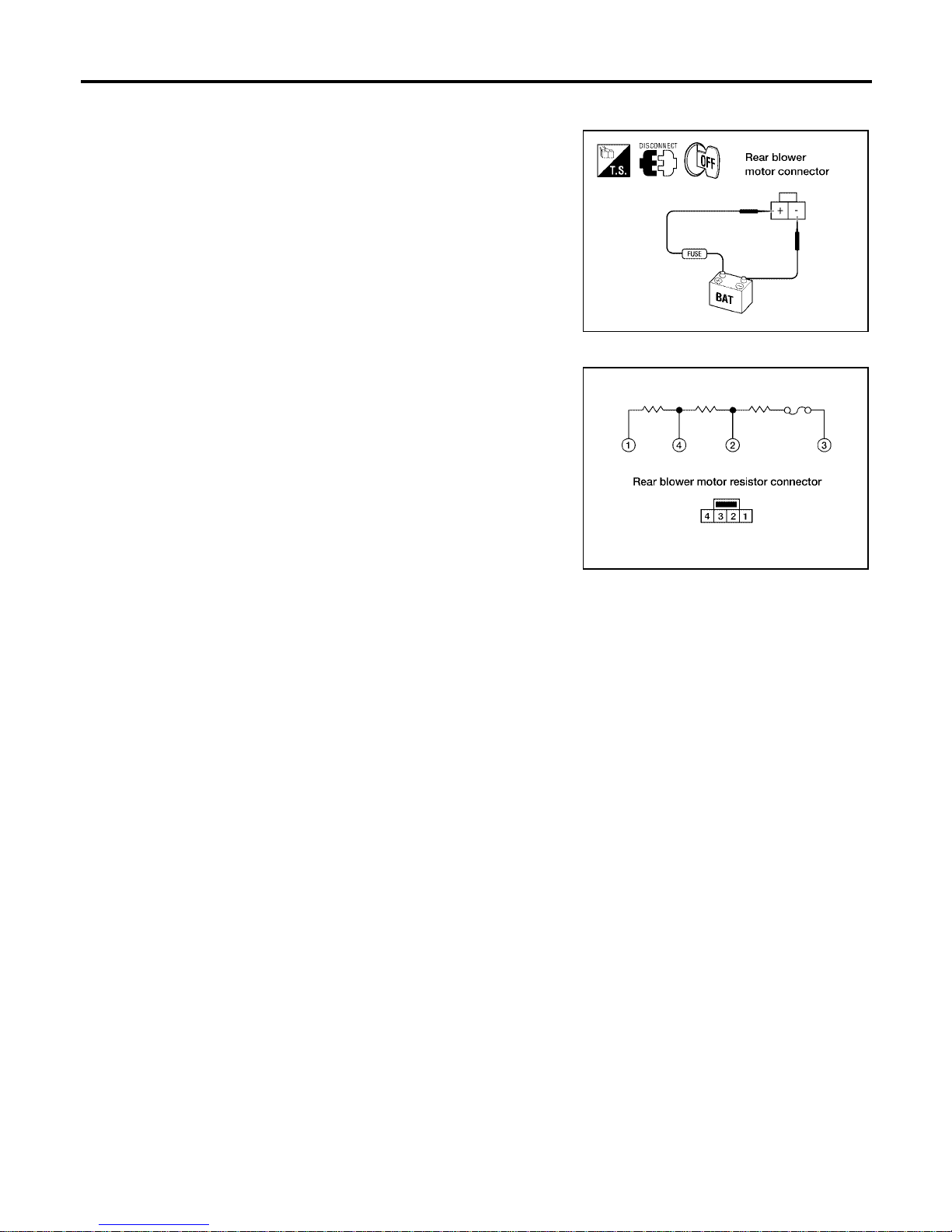
MTC-90
TROUBLE DIAGNOSIS
Revision: January 2005 2004 Quest
Rear Blower Motor
Check that there are no foreign particles inside the intake unit.
Apply 12 volts to terminal + and ground to terminal - and ensure that
the blower motor rotates freely and quietly.
Rear Blower Motor Resistor
Check continuity between terminals. There will be resistance, but
there should not be an open or short between any two terminals.
LJIA0115E
LJIA0116E
Page 91
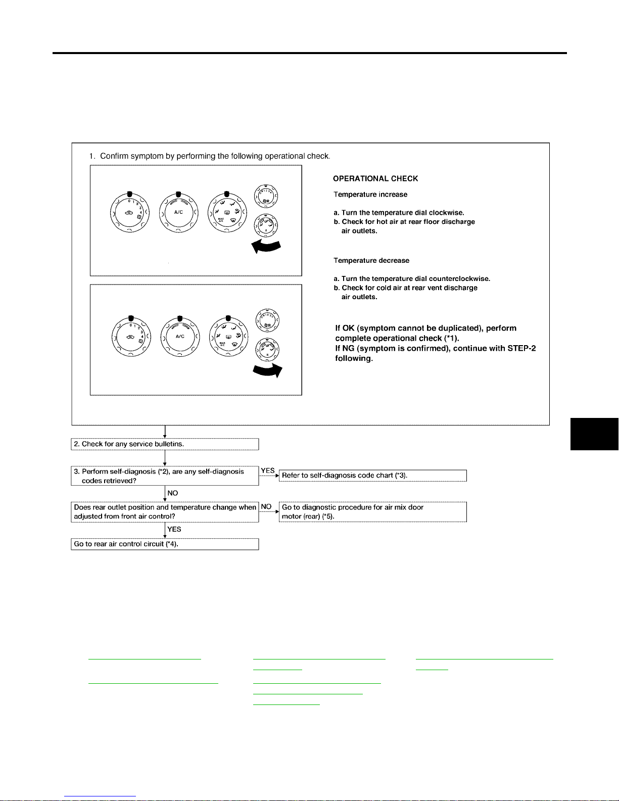
TROUBLE DIAGNOSIS
MTC-91
C
D
E
F
G
H
I
K
L
M
A
B
MTC
Revision: January 2005 2004 Quest
Rear Air Control Circuit EJS001SO
SYMPTOM:
● Temperature cannot be adjusted from the rear air control.
INSPECTION FLOW
*1 MTC-52, "Operational Check".*2MTC-50, "A/C System Self-diagno-
sis Function".
*3 MTC-51, "
SELF-DIAGNOSIS CODE
CHART".
*4 MTC-91, "Rear Air Control Circuit".*5MTC-64, "DIAGNOSTIC PROCE-
DURE FOR AIR MIX DOOR
MOTOR (REAR)".
WJIA0519E
Page 92
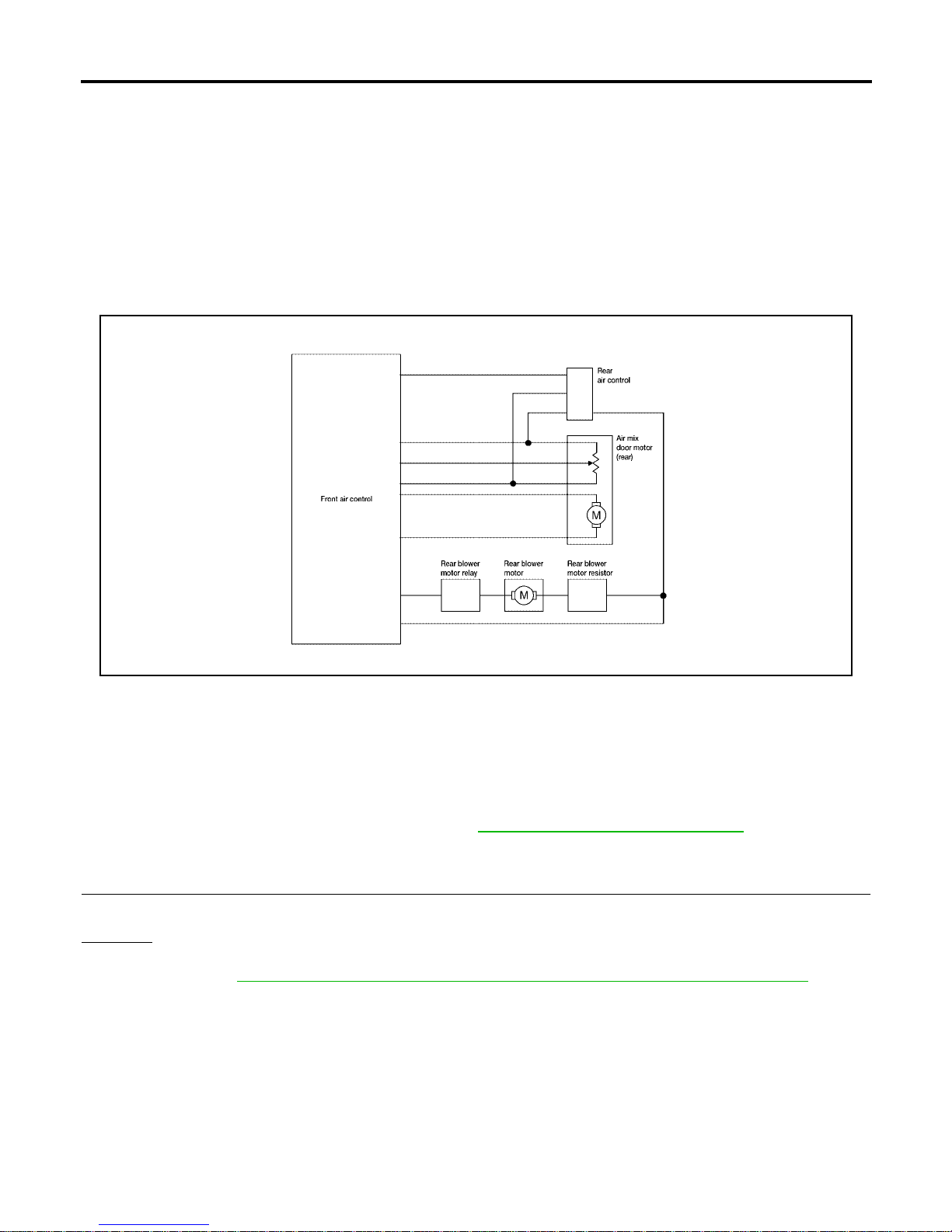
MTC-92
TROUBLE DIAGNOSIS
Revision: January 2005 2004 Quest
SYSTEM DESCRIPTION
Component Parts
Rear air control system components are:
● Front air control
● Rear air control
● Air mix motor (rear)
● Rear blower relay
● Rear blower motor resistor
● Rear blower motor
System Operation
Rear Air Control
When the rear blower switch (front) (integral to the front air control) is in the REAR position the rear blower
motor speeds and the rear temperature/mode are controlled by the rear blower switch (rear) and the rear temperature switch (rear) (both integral to the rear air control).
DIAGNOSTIC PROCEDURE FOR REAR AIR CONTROL
SYMPTOM:
● Blower motor operation is malfunctioning. Refer to MTC-80, "Rear Blower Motor C ircuit" .
● Temperature/m ode operation is malfunctioning.
1. CHECK OPERATION FROM FRONT AIR CONTROL
Does rear temperature/mode operate normally from front air control?
Yes or No
Yes > > GO TO 2.
No >> Refer to MTC-64, "
DIAGNOSTIC PROCEDURE FOR AIR MIX DOOR MOTOR (REAR)" .
LJIA0120E
Page 93
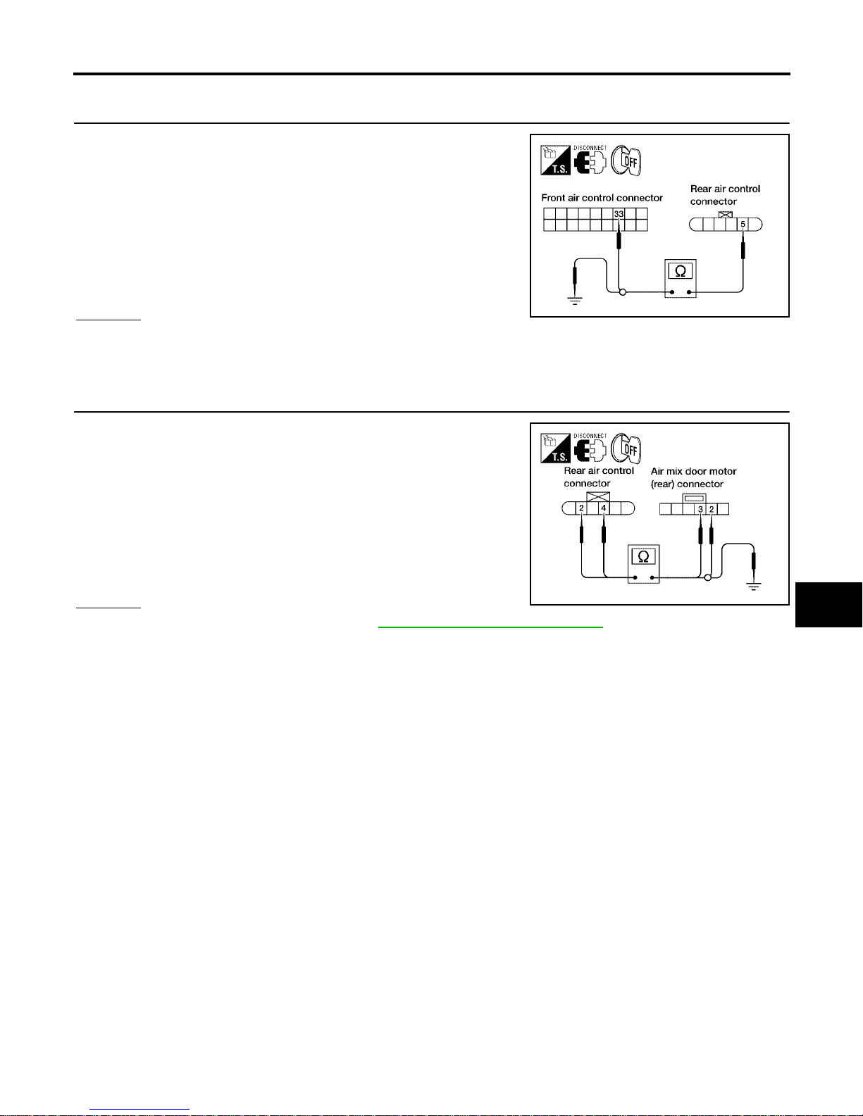
TROUBLE DIAGNOSIS
MTC-93
C
D
E
F
G
H
I
K
L
M
A
B
MTC
Revision: January 2005 2004 Quest
2. CHECK CIRCUIT BETWEEN REAR AIR CONTROL AND FRONT AIR CONTROL FOR OPEN OR
SHORT
1. Disconnect front air control and rear air control connectors .
2. Check continuity between front air control harness connector
M50 terminal 33 (V) and rear air control harness connector B142
terminal 5 (V).
3. Check continuity between rear air control harness connector
B142 terminal 5 (W/G) and ground.
OK or NG
OK >> GO TO 3.
NG >> Repair harness or connector.
3. CHECK CIRCUIT BETWEEN REAR AIR CONTROL AND AIR MIX DOOR MOTOR (REAR) FOR OPEN
OR SHORT
1. Disconnect air mix door motor (rear) connectors.
2. Check continuity between rear air control harness connector
B142 terminal 2 (W/G) and 4 (Y) and air mix door motor (rear)
harness connector B146 terminal 2 (Y) and 3 (W/G).
3. Check continuity between rear air control harness connector
B142 terminals 2 (W/G) and 4 (Y) and ground.
OK or NG
OK >> Replace rear air control. Refer to MTC-116, "REAR AIR CONTROL" .
NG >> Repair harness or connector.
Continuity should exist.
Continuity should not exist.
LJIA0121E
Continuity should exist.
Continuity should not exist.
LJIA0122E
Page 94
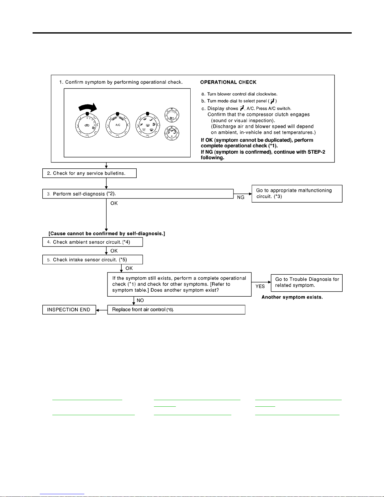
MTC-94
TROUBLE DIAGNOSIS
Revision: January 2005 2004 Quest
Magnet Clutch Circuit EJS001SP
SYMPTOM: Magnet clutch does not engage.
INSPECTION FLOW
*1 MTC-52, "Operational Check " *2 MTC-50, "A/C System Self-diagnosis
Function".
*3 MTC-51, "
SELF-DIAGNOSIS CODE
CHART".
*4 MTC-111, "
Ambient Sensor Circuit".*5MTC-113, "Intake Sensor Circuit".*6MTC-11 6, "FRONT AIR CONTROL"
WJIA1619E
Page 95
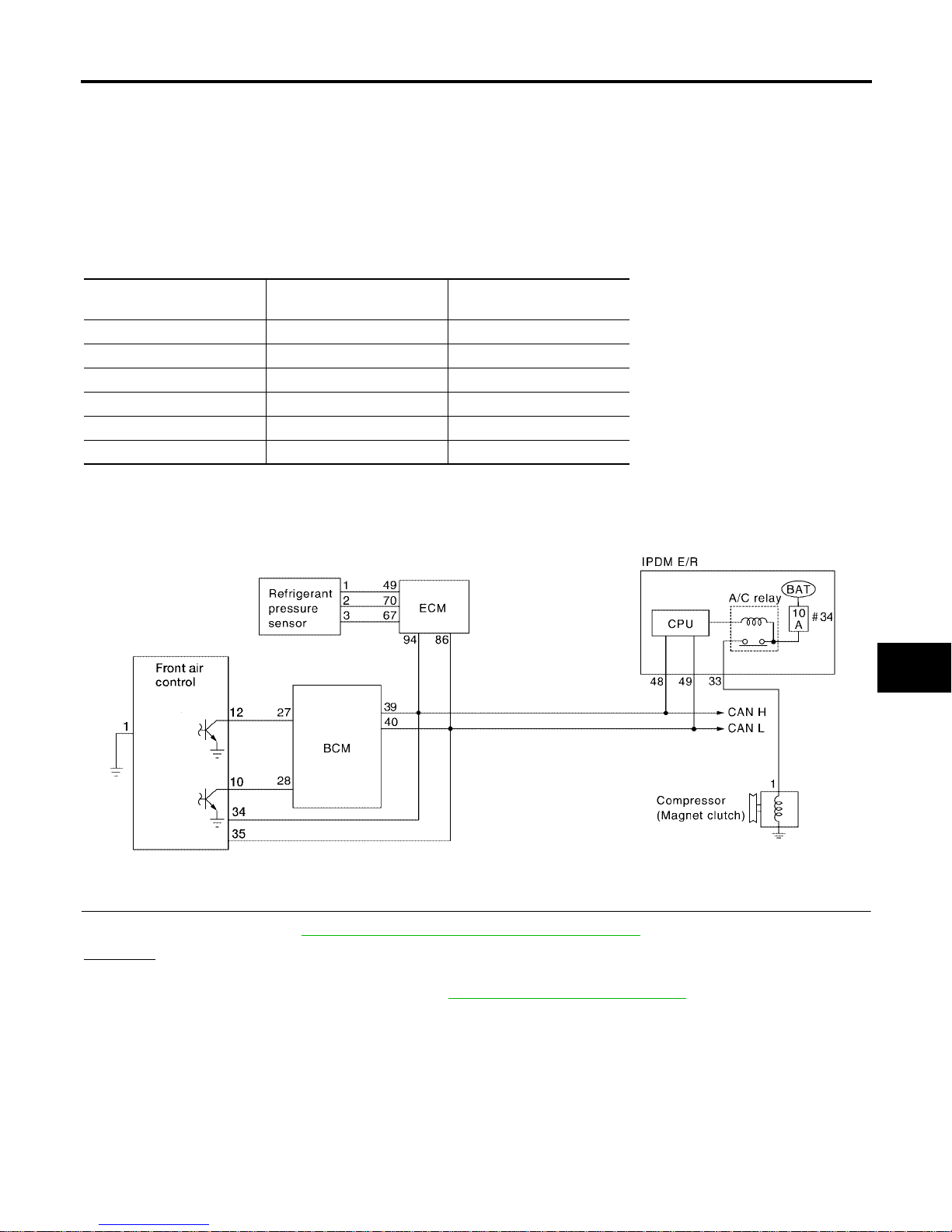
TROUBLE DIAGNOSIS
MTC-95
C
D
E
F
G
H
I
K
L
M
A
B
MTC
Revision: January 2005 2004 Quest
SYSTEM DESCRIPTION
The front air contro l controls compressor op eration based on ambien t and intake temperature and a s ignal
from ECM.
Low Te mp eratur e Protectio n Con t rol
The front air control will turn the compressor ON or OFF as determined by a signal detected by the intake sensor and the ambient sensor.
When intake air temperature is higher than the preset value, the compressor turns ON. The compressor turns
OFF when intake air temperature is lower than the preset value. That preset value is dependent on the ambient temperature. Refer to the following table.
DIAGNOSTIC PROCEDURE FOR MAGNET CLUTCH
SYMPTOM: Magnet clutch does not engage when A/C switch is ON.
1. CHECK INTAKE SENSOR CIRCUIT
Check intake sensor. Refer to MTC-50, "
A/C System Self-diagnosis Fun c tio n" .
OK or NG
OK >> GO TO 2.
NG >> Malfunctioning intake sensor. Refer to MTC-113, "
Intake Sensor Circuit" .
Ambient temperature °C (°F)
Compressor ON
intake temperature C (°F)
Compressor OFF
intake temperature C (°F)
0 (32) 2.5 (37) 2.0 (36)
10 (50) 2.5 (37) 2.0 (36)
20 (68) 2.5 (37) 1.5 (35)
30 (86) 2.0 (36) 0.5 (33)
40 (104) 2.0 (36) 0.5 (33)
50 (122) 2.0 (36) 0.5 (33)
WJIA0472E
Page 96
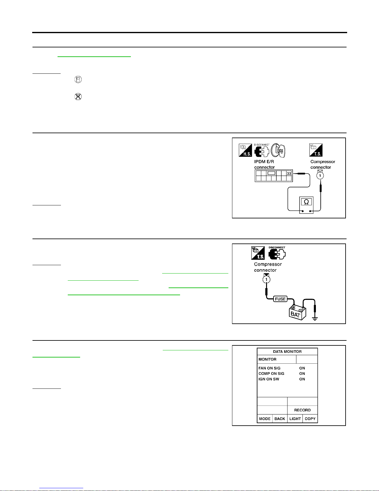
MTC-96
TROUBLE DIAGNOSIS
Revision: January 2005 2004 Quest
2. PERFORM AUTO ACTIVE TEST
Refer to PG-21, "
Auto Active T e st" .
Does magnet clutch operate?
Yes or No
Yes >> ● WITH CONSULT-II
GO TO 5.
● WITHOUT CONSULT-II
GO TO 6.
No >> Check 10A fuse (No. 33, located in IPDM E/R), and GO TO 3.
3. CHECK CIRCUIT CONTINUITY BETWEEN IPDM E/R AND COMPRESSOR
1. Turn ignition switch OFF.
2. Disconnect IPDM E/R connector and compressor (magnet
clutch) connector.
3. Check continuity between IPDM E/R harness connector E124
terminal 33 (Y/B) and compressor harness connector F3 terminal 1 (Y/B).
OK or NG
OK >> GO TO 4.
NG >> Repair harness or connector.
4. CHECK MAGNET CLUTCH CIRCUIT
Check for operati on soun d when app lying batte ry voltage di rect current to terminal.
OK or NG
OK >> Replace IPDM E/R. Refer to PG-27, "Removal and
Installation of IPDM E/R" .
NG >> Replace magnet clutch. Refer to MTC-149, "
Removal
and Installation for Compresso r Clutc h" .
5. CHECK BCM INPUT (COMPRESSOR ON) SIGNAL
Check compressor ON/ OFF signal. Refer to MTC- 31, "
CONSULT-II
Function (BCM)" .
OK or NG
OK >> GO TO 8.
NG >> GO TO 6.
33 – 1 : Continuity should exist.
WJIA0331E
SJIA0197E
A/C SW ON : COMP ON SIG ON
A/C SW OFF : COMP ON SIG OFF
WJIA0469E
Page 97
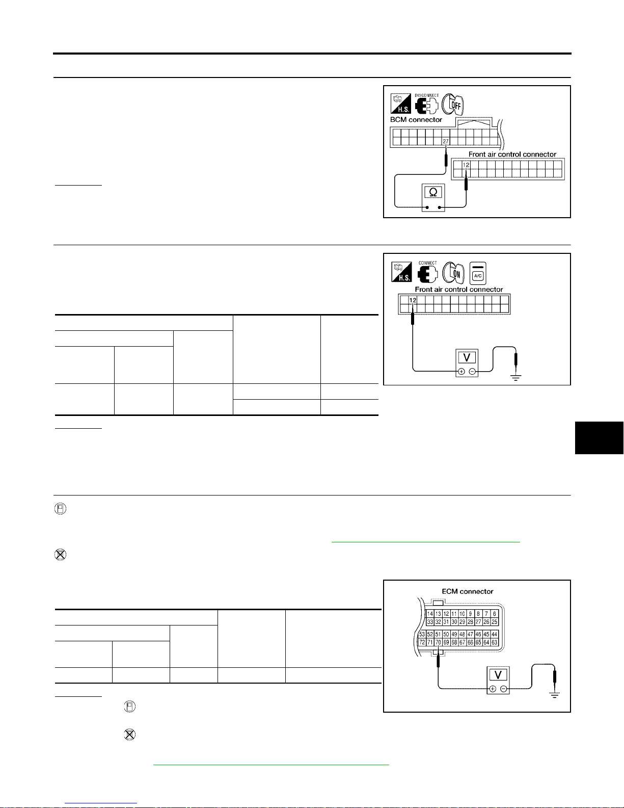
TROUBLE DIAGNOSIS
MTC-97
C
D
E
F
G
H
I
K
L
M
A
B
MTC
Revision: January 2005 2004 Quest
6. CHECK CIRCUIT CONTINUITY BETWEEN BCM AND FRONT AIR CONTROL
1. Turn ignition switch OFF.
2. Disconnect BCM connector and front air control connector.
3. Check continuity bet ween B CM har ness conn ecto r M18 termi nal
27 (L/R) and fr ont ai r co nt ro l h ar nes s co nn ec to r M4 9 t e rmi nal 12
(L/R).
OK or NG
OK >> GO TO 7.
NG >> Repair harness or connector.
7. CHECK VOLTAGE FOR FRONT AIR CONTROL (COMPRESSOR ON SIGNAL)
1. Reconnect BCM connector and front air control connector.
2. Turn ignition switch ON.
3. Check voltage between front air control harness connector M49
terminal 12 (L/R) and ground.
OK or NG
OK >> GO TO 8.
NG-1 >> If the voltage is approx. 5V when A/C switch is ON, repl ace front air cont rol.
NG-2 >> If the voltage is approx. 0V when A/C s witch is OFF, replace BCM.
8. CHECK REFRIGERANT PRESSURE SENSOR
WITH CONSUL T-II
1. Start engine.
2. Check voltage of refrigerant pressure sensor. Refer to MTC-31, "
CONSULT-II Function (BCM)" .
WITHOUT CONSUL T-II
1. Start engine.
2. Check voltage between ECM harness connector F54 terminal
70 (W) and groun d.
OK or NG
OK >> ● WITH CONSULT-II
GO TO 9.
● WITHOUT CONSULT-II
GO TO 10.
NG >> Refer to EC-682, "
REFRIGERANT PRESSURE SENSOR" .
Continuity should exist.
WJIA0974E
Terminals
Condition
Voltage
(Approx.)
(+)
(-)
Front air
control con-
nector
Terminal No.
(Wire color)
M49 12 (L/R) Ground
A/C switch: ON 0V
A/C switch: OFF 5V
WJIA0449E
Terminals
Condition
Voltage
(Approx.)
(+)
(-)
ECM con-
nector
Terminal No.
(Wire color)
F54 70 (W) Ground A/C switch: ON 3.6 - 3.88V
LJIA0124E
Page 98
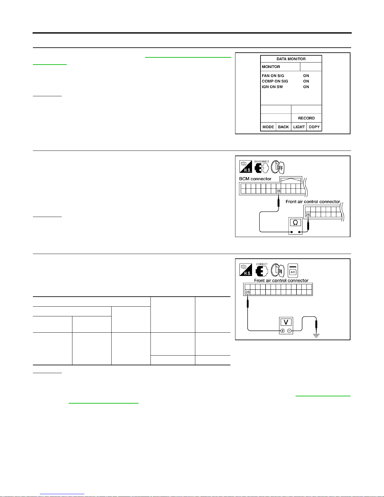
MTC-98
TROUBLE DIAGNOSIS
Revision: January 2005 2004 Quest
9. CHECK BCM INPUT (FAN ON) SIGNAL
Check FAN ON/OFF signal. Refer to MTC-31, "
CONSULT-II Func-
tion (BCM)" .
OK or NG
OK >> GO TO 12.
NG >> GO TO 10.
10. CHECK CIRCUIT CONTINUITY BETWEEN BCM AND FRONT AIR CONTROL
1. Turn ignition switch OFF.
2. Disconnect B CM co nn ec tor and front air control connec to r.
3. Check continui ty be tween BCM harnes s conne cto r M18 ter min al
28 (L/Y) and front air control harness connector M49 terminal 26
(G/B).
OK or NG
OK >> GO TO 11.
NG >> Repair harness or connector.
11. CHECK VOLTAGE FOR FRONT AIR CONTROL (FAN ON SIGNAL)
1. Reconnect BC M connector and front air control connector.
2. Turn ignition switch ON.
3. Check voltage between front air control harness connector M49
terminal 26 (G/B) and ground.
OK or NG
OK >> GO TO 12.
NG-1 >> If the voltage is approx. 5V when blower motor is ON, replace front air control.
NG-2 >> If the voltage is approx. 0V when blower motor is OFF, replace BCM. Refer to BCS-19, "
Removal
and Installation of BCM" .
FAN CONTROL SWITCH ON : FAN ON SIG ON
FAN CONTROL SWITCH OFF : FAN ON SIG OFF
WJIA0469E
Continuity should exist.
WJIA0975E
Terminals
Condition
Voltage
(Approx.)
(+)
(-)
Front air control connector
Termi nal No.
(Wire color)
M49 26 (G/B) Ground
A/C switch: ON
Blower motor
operates
0V
A/C switch: OFF 5V
WJIA0976E
Page 99
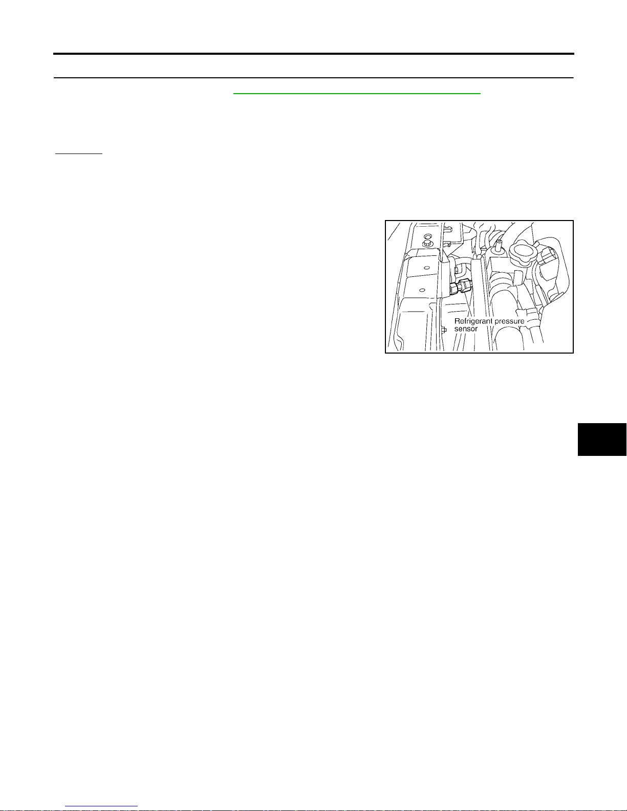
TROUBLE DIAGNOSIS
MTC-99
C
D
E
F
G
H
I
K
L
M
A
B
MTC
Revision: January 2005 2004 Quest
12. CHECK CAN COMMUNICATION
Check CAN communication. Refer to MTC-30, "
CAN Communication System Description" .
● BCM – ECM
● ECM – IPDM E/R
● ECM – Front air control
OK or NG
OK >> Inspection End.
NG >> Repair or replace malfunctioning part(s).
COMPONENT INSPECTION
Refrigerant Pressure Sensor
The refrigerant pressure sensor is attached to the condenser.
RJIA1795E
Page 100
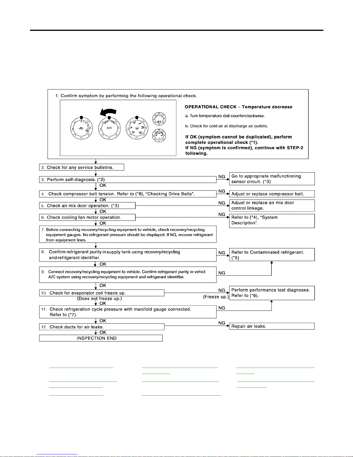
MTC-100
TROUBLE DIAGNOSIS
Revision: January 2005 2004 Quest
Insufficient Cooling EJS001SQ
SYMPTOM: Insufficient cooling
INSPECTION FLOW
*1 MTC-52, "Operational Check".*2MTC-50, "A/C System Self-diagno-
sis Function".
*3 MTC-51, "
SELF-DIAGNOSIS CODE
CHART".
*4 EC-472, "
DTC P1217 ENGINE
OVER TEMPERATURE"
*5 MTC-5, "Contaminated Refrigerant".*6 .MTC-101, "PERFORMANCE TEST
DIAGNOSES"
*7 MTC-104, "Test Reading" *8 MA-12, "CHECKING DRIVE BELTS"
WJIA1029E
 Loading...