

Page 1

To reduce the risk of electric shock do not remove cover(or back)
No user serviceable parts inside. Refer servicing to qualified service personnel.
Design and specification are subject to change without notice.
The exclamation point within an equilateral triangle is intended to alert
the user to the presence of important operating and maintenance
(servicing) instructions in the literature accompanying the appliance.
The lightning flash with arrowhead symbol,within an equilateral
triangle,is intended to alert the user to the presence of uninsulated
"dangerous voltage" within the product's enclosure that may be of
sufficient magnitude to constitute a risk of electric shock to persons.
WARNING
RISK OF ELECTRIC SHOCK
DO NOT OPEN
USER GUIDE
7”Wide TFT LCD Color Rear View System
MTB-7300
Page 2
CAMERA
SUN SHIELD WITH PROTECTION RUBBER (PATENT PENDING)
- 1 -
MONITOR
ACCESSORIES
HEAVY DUTY BRACKET KIT / STAND BRACKET(OPTION)
BUILT- IN REMOTE RECEIVER (OPTIONAL)
BUILT- IN SPEAKER (1W)
RUBBER TOUCH NEUTRAL BLACK
AUTOMATIC SCREEN-ON (SIGNAL FROM "R"GEAR)
NOR./ MIR.& UP / DOWN IMAGE REVERSING
SHUTTER CAMERA (HEATER)
NORMAL CAMERA
4:3 / 16:9 WIDE SCREEN
181(W) x 122 (H) x 24(D)mm (7.13x4.8x0.94 Inch)
DC 10V ~
30
V (Free voltage)
POWER & CAMERA INPUT CABLE /
WATERPROOF / SUN SHIELD / IR SENSOR / NORMAL / MIRROR / HEATER (OPTIONAL)
DIMMER
REMOTE CONTROL
HOUSING
RESOLUTION
DISPLAY MODE
3 CAMERAS INPUT
SCREEN MODE
BRIGHTNESS
AUDIO OUTPUT
DIMENSION
POWER SOURCE
CAR REAR VIEW
SIZE
SPECIFICATION
BUILT- IN CDS SENSOR Automatical / Manual
1440 (W) x 234(H) Pixels
500 cd / m
OPERATING TEMP.
WEIGHT
-30 C ~ 85 C
STARAGING TEMP.
-20 C ~ 70 C
450 (g)
VIEW ANGLE
TOP: 40 BOTTOM: 60 LEFT: 60 RIGHT: 60
2
°
°
°
°
-2-
MTB-7300 MONITOR
Checking the main unit and supplied accessories
II
Features / Technical Specications
I
Contents
Operations
III
4-8
Checking the main unit and supplied accessories
II
2-3
Features / Technical Specications
I
1
Using MTB-7300 in the Vechile
IV
11
Sun Shield
VI
11
System Wiring
V
12
MTB-10C Rear View Camera
VII
13~14
X
wv~ly
tlu|
kpt
zjhuOP
jhUzlsOP
}vs|tlOP
}vs|tlOP
Y
Z
[
]
^
_
\
XY
]
^
_
Z
[
\
jGzluzvy
°°
°°
Page 3

-3-
- 4 -
Accessories
z h
Power
&
Camera
Input Cable
Stand Bracket Kit (Option)
Rubber Sun Shield
User’s Guide
Heavy Duty Bracket Kit
- If the Menu Key is pressed at the POWER ON mode, the OSD appears
in the monitor and the selected letters on OSD is classified in a different color.
- If pressing of the Menu Key is repeated in OSD state, the display
is circled in regular sequence of FUNCTION
PICTURE
CAMERA
Clear of OSD.
the sequence will be as below without the CAMERA OSD.
FUNCTION
PICTURE Clear of OSD.
- When POWER OFF (which means STANDBY state), the LED has
RED color.
- After POWER ON, the LED in RED color is turned off and all
LEDs light in GREEN color.
- After POWER ON, the LAST CHANNEL saved from its last operation
is displayed on the monitor.
(Factory Default).
- DIRECT POWER ON Subject To LAST POWER SAVE Mode:
* After starting up the vehicle engine, the monitor turns on automatically
at the same time and the monitor starts displaying of the views from the
(1) If the vehicle engine had been turned off at the POWER ON state of monitor,
the LAST POWER SAVE mode is ON (Factory Recommendation).
(2) If the vehicle engine had been turned off after the POWER OFF of monitor,
the LAST POWER SAVE mode is OFF.
cameras if the LAST POWER SAVE mode is ON.
Operations
III
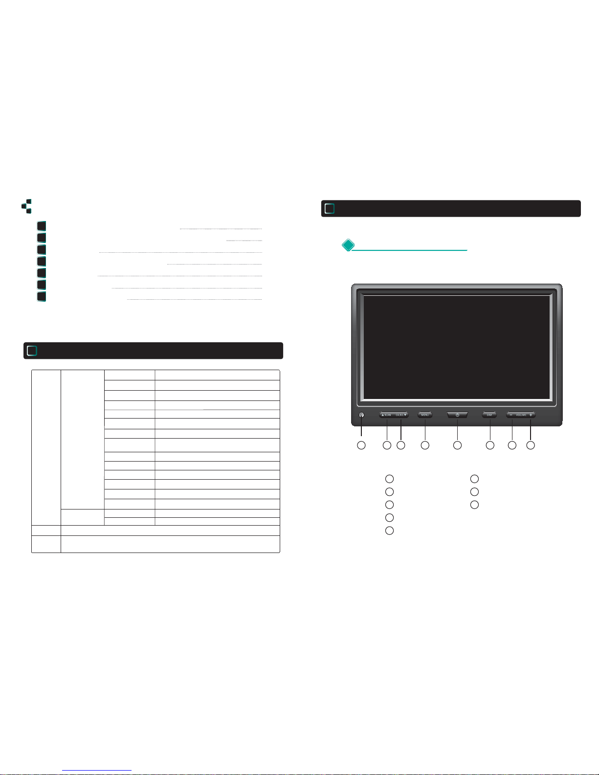
1 Power Key
2 Menu Key
A
Menu Control Keys
FUNCTION
LANGUAGE
ENGLISH
DIRECTION
DIMMER
RESET ENTER
0/180
AUTO/OFF
NTSC/PAL
PICTURE
CONTRAST
BRIGHT
COLOR
TINT
50 (0-100)
50 (0-100)
50 (0-100)
50 (0-100)
NOR/MIR
NOR/MIR
NOR/MIR
CAMERA
CA1 SCAN
CA2 SCAN
CA3 SCAN
CA1 TRIG
0 ~ 9
0 ~ 9
0 ~ 9
0 ~ 9
CA3 TRIG
0 ~ 9
CA2 TRIG
0 ~ 9
Page 4
-5-
-6-
50
VOLUME
- The brightness is adjusted manually at the POWER ON mode,
if DIMMER is selected in OSD set-up.
Pressing of DIMMER Key in this condition makes the change
of brightness responding on every manual operation of the Key.
- If pressing of the SCAN Key is repeated at the POWER ON mode, the display
is revolved in sequence of SCAN1
SCAN2
SCAN3
- In OSD state, this SCAN Key is in use of moving a cursor to
downward as well.
- If pressing of the CA.SEL Key is repeated at the POWER ON mode,
the CHANNEL is changed in regular sequence of
CA1
CA2
CA3
- In OSD state, pressing of these VOLUME Up / Down KEYS makes
the selected function to be adjusted and changed its status to new setup.
- Pressing of these VOLUME Up / Down KEYS at POWER ON mode makes
that the audio volume of the monitor is increased and/or decreased.
VOLUME Down KEY: To decrease the VOLUME
VOLUME Up KEY: To increase the VOLUME
Adjustable volume range from 0 to 100 (0 ~ 100)
Factory Default: 50
3 DIMMER Key
4 SCAN(Up) Key
5 CA.SEL(down) Key
6.7
VOLUME Up / Down Key
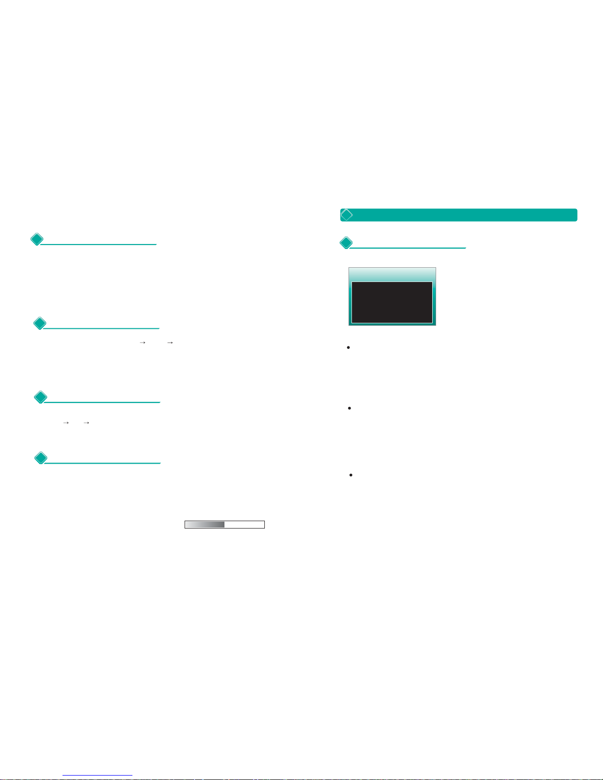
DIRECTION
- Locate the cursor at DIRECTION by SCAN and/or CA.SEL Keys.
- Select the desired direction by VOLUME Up/Down Keys.
- 0 : Normal Screen (Factory Default)
- 180 : Shifted Screen to 180°reversely.
DIMMER SELECT KEY
- Locate the cursor at SELECT KEY by SCAN and/or CA.SEL Keys.
- Select DIM by VOLUME Up/Down Keys.
- DIM : Release AUTO DIMMER and adjust the brightness manually by
pressing of DIMMER Key.
Language : 6 Languages
ENGLISH, GERMAN, FRENCH, ITALIAN, SPANISH, DUTCH
- Locate the cursor at LANGUAGE by SCAN and/or CA.SEL keys.
- Select the desired language by VOLUME Up/Down Keys.
- Factory default is ENGLISH.
1 FUNCTION
B
How to set up the functions of the Menu on OSD
FUNCTION
LANGUAGE
ENGLISH
DIRECTION
DIMMER
RESET ENTER
0/180
AUTO/OFF
Page 5
-7-
-8-
3 CAMERA
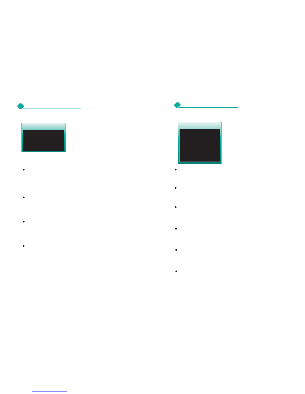
CONTRAST
- Display PICTURE set-up Screen by pressing the MENU Key twice
and locate the cursor at CONTRAST by SCAN and/or CA,SEL Keys.
- Adjust the Contrast by the Volume Up/Down Keys.
0 ~ 100 / 50 : Factory Default
BRIGHTNESS
- After locating the cursor at BRIGHT by SCAN and/or CA.SEL Keys,
adjust the Brightness by the Volume Up/Down Keys.
0 ~ 100 / 50 : Factory Default
COLOR
- After locating the cursor at COLOR by SCAN and/or CA.SEL Keys,
adjust the Color by the Volume Up/Down Keys.
0 ~ 100 / 50 : Factory Default
TINT
- After locating the cursor at TINT by SCAN and/or CA.SEL Keys,
adjust the Tint by the Volume Up/Down Keys.
0 ~100 / 50 : Factory Default
2 PICTURE
PICTURE
CONTRAST
BRIGHT
COLOR
TINT
50 (0-100)
50 (0-100)
50 (0-100)
50 (0-100)
NOR/MIR
NOR/MIR
NOR/MIR
CAMERA
CA1 SCAN
CA2 SCAN
CA3 SCAN
CA1 TRIG
0 ~ 9
0 ~ 9
0 ~ 9
0 ~ 9
CA3 TRIG
0 ~ 9
CA2 TRIG
0 ~ 9
CA1 TRIG
CA1 SCAN
- After locating the cursor at CA 1 SCAN by SCAN and/or CA.SEL Keys,
select the desired delaying time for the selected viewing mode among
0 ~ 9 seconds by Volume Up/Down Keys.
- Factory Default : 3 second
CA2 SCAN
- After locating the cursor at CA 2 SCAN by SCAN and/or CA.SEL Keys,
select the desired delaying time for the selected viewing mode among
0 ~ 9 seconds by Volume Up/Down Keys.
- Factory Default : 3 seconds
CA3 SCAN
- After locating the cursor at CA 3 SCAN by SCAN and/or CA.SEL Keys,
select the desired delaying time for the selected viewing mode among
0 ~ 9 seconds by Volume Up/Down Keys.
- Factory Default : 3 seconds
- After locating the cursor at CA 1 TRIG by SCAN and/or CA.SEL Keys,
select the desired delaying time for the selected viewing mode among
0 ~ 9 seconds by Volume Up/Down Keys.
- Factory Default : 3 seconds
- After locating the cursor at CA 2 TRIG by SCAN and/or CA.SEL Keys,
select the desired delaying time for the selected viewing mode among
0 ~ 9 seconds by Volume Up/Down Keys.
- Factory Default : 3 seconds
CA3 TRIG
- After locating the cursor at CA 3 TRIG by SCAN and/or CA.SEL Keys,
select the desired delaying time for the selected viewing mode among
0 ~ 9 seconds by Volume Up/Down Keys.
- Factory Default : 3 seconds
CA2 TRIG
Page 6

-9-
-10-
3 CAMERA
4 CAMERA
CAM MODUS
CA 1
CA 3
NORMAL/SHUTTER
ON/OFF
NOR/MIR
NOR/MIR
NOR/MIR
CAMERA
CAM1 N/M
CAM2 N/M
CAM3 N/M
CAM1 DIST ON/OFF
NORMAL/MIRROR
NORMAL/MIRROR
NORMAL/MIRROR
CAM3 DIST
ON/OFF
CAM2 DIST
ON/OFF
CAMERA1
- Display NOR/MIR set-up Screen by pressing the MENU Key 9 times
and locate the cursor at CAM1 by SCAN and/or CA.SEL Keys.
- Select the desired viewing mode between NOR and MIR by Volume Up/Down Keys.
- NOR : Normal Image / Factory Default
MIR : Mirror Image
(Symmetrically Reversed Image of Left & Right against Normal Image)
CAMERA2
- After locating the cursor at CAM2 by SCAN and/or CA.SEL Keys,
select the desired viewing mode between NOR and MIR by Volume
Up/Down Keys.
- NOR : Normal Image / Factory Default
MIR : Mirror Image
(Symmetrically Reversed Image of Left & Right against Normal Image)
CAMERA3
- After locating the cursor at CAM3 by SCAN and/or CA.SEL Keys,
select the desired viewing mode between NOR and MIR by Volume Up/Down Keys.
- NOR : Normal Image / Factory Default
MIR : Mirror Image
(Symmetrically Reversed Image of Left & Right against Normal Image)
DISTANCE
- Locate the cursor at DISTANCE by SCAN and/or CA.SEL Keys.
- Select ON or OFF by VOLUME Up/Down Keys.
- ON : The rear scale OSD is displayed on the monitor.(Factory Default)
- OFF: No rear scale OSD is displayed on the monitor.
- From the POWER OFF state of the monitor, if the CA1~3 is turned on by
Trigger1 ~ 3, the rear scale OSD is displayed on the monitor but DISTANCE must be
ON in OSD setting.
CAM / MODUS
- Display CAM / MODUS set-up Screen by pressing the MENU Key 9 times and locate the
cursor at CAM / MODUS by SCAN and/or CA.SEL Keys.
- After locating the cursor at CA1 by SCAN and/or CA.SEL Keys,select the desired
CAM / MODUS to view among the cameras NORMAL/MIRROR by Volume Up/Down Keys.
- After locating the cursor at CA3 by SCAN and/or CA.SEL Keys,select the desired
CAM / MODUS to view among the cameras ON/OFF by Volume Up/Down Keys.
Page 7
By setting up
MTB- 10C
with the Sun Shield which has
the rubber guide for protection,
the
MTB-10C
will be shielded off the direct sunlight.
The Sun Shield will offer visual comfort for driving and
will make driving safer
&
more comfortable.
○ After connecting power to the unit through t he Ci gar e tte adaptor, press
[Power button] on the main unit or on the Remote Control to power on.
○ Set up
MTB- 10C
with Stand Bracket Kit and fix the Stand Bracket Kit
on the dashboard of the car.
-11-
- 12 -
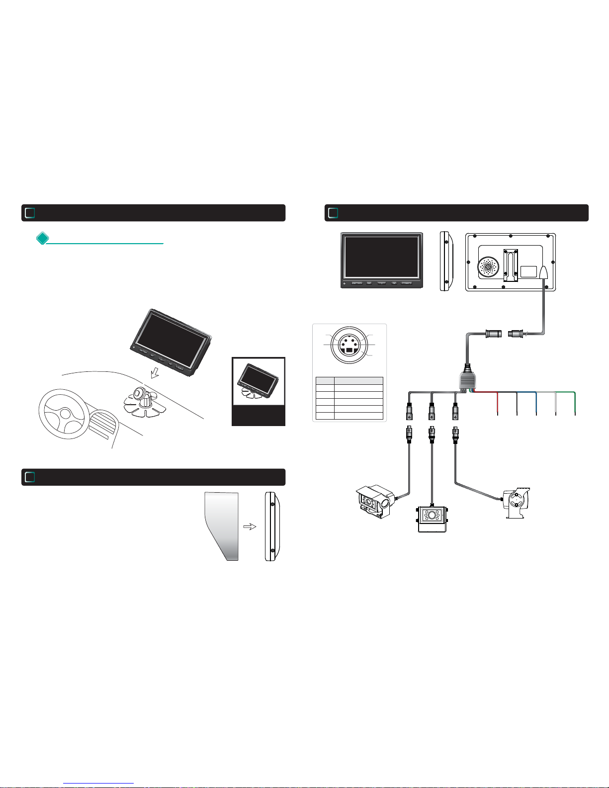
FRONT VIEW
For using MTB-10C on the dashboard
Using MTB-10C in the Vehicle
IV
System Wiring
VI
Sun Shield
V
Fasten the bolt
to fix the main unit
to Stand Bracket Kit.
Fixon the dashbord
in the car
BACK VIEWSIDE VIEW
EXTENSION CABLE
NORMAL CAMERA
NORMAL CAMERA
ACC 10~30V
Trigger 3
12~30V
Trigger 1
12~30V
Ground
Trigger 2
12~30V
MONITOR CONNECTION
HEATER(OPTIONAL)
DC12V POWER
VIDEO IN
DESCRIPTION
3
GROUND
5
4
AUDIO IN
PIN NO.
2
1
1
5
3
4
2
NORMAL CAMERA or
AUTO SHUTTER CAMERA
CA 1
CA 3
CA 2
Red Black
White
Blue
Green
Page 8
-14-
-13-
2 Specifications
IMAGE SENSOR
EFFECTIVE PIXELS
RESOLUTION
SYNCHRONIZING SYSTEM
VIDEO OUTPUT
AUDIO INPUT
S/N RATIO
REQUIRED .ILLUMINATION
POWER SOURCE
FIELD OF VIEW / OPTION
OPERATING TEMPERATURE
DIMENSION
WEIGHT
ACCESSORIES
BEST NIGHT VIEW FEATURE
1/3" Sony Super HAD Color CCD
(Compatible with Sharp CCD)
PAL : 320,000 Pixels
380 TV Lines
Internal
75 Ohms ,1.0Vp-p Composite.
High Sensitive C-Microphone
More than 48dB
0 Lux at F2.0 / f =2.45mm (LED ON)
DC 12V / Max. 150mA (LED ON)
-30°C ~ +60°C
-50°C ~ +60°C
(With Heater)
69(W) X 42(H) X57(D) mm
2.7(W) X 1.65(H) X 2.2(D) inch
650g
20M Waterproof cable (Option)
Sun Shield
Mounting Bracket and Screw Kits
20 degrees visible IR LED X 6ea
120° 130° 150°
OPERATING VOLTAGE RANGE
DC 12V (Powered by monitor)
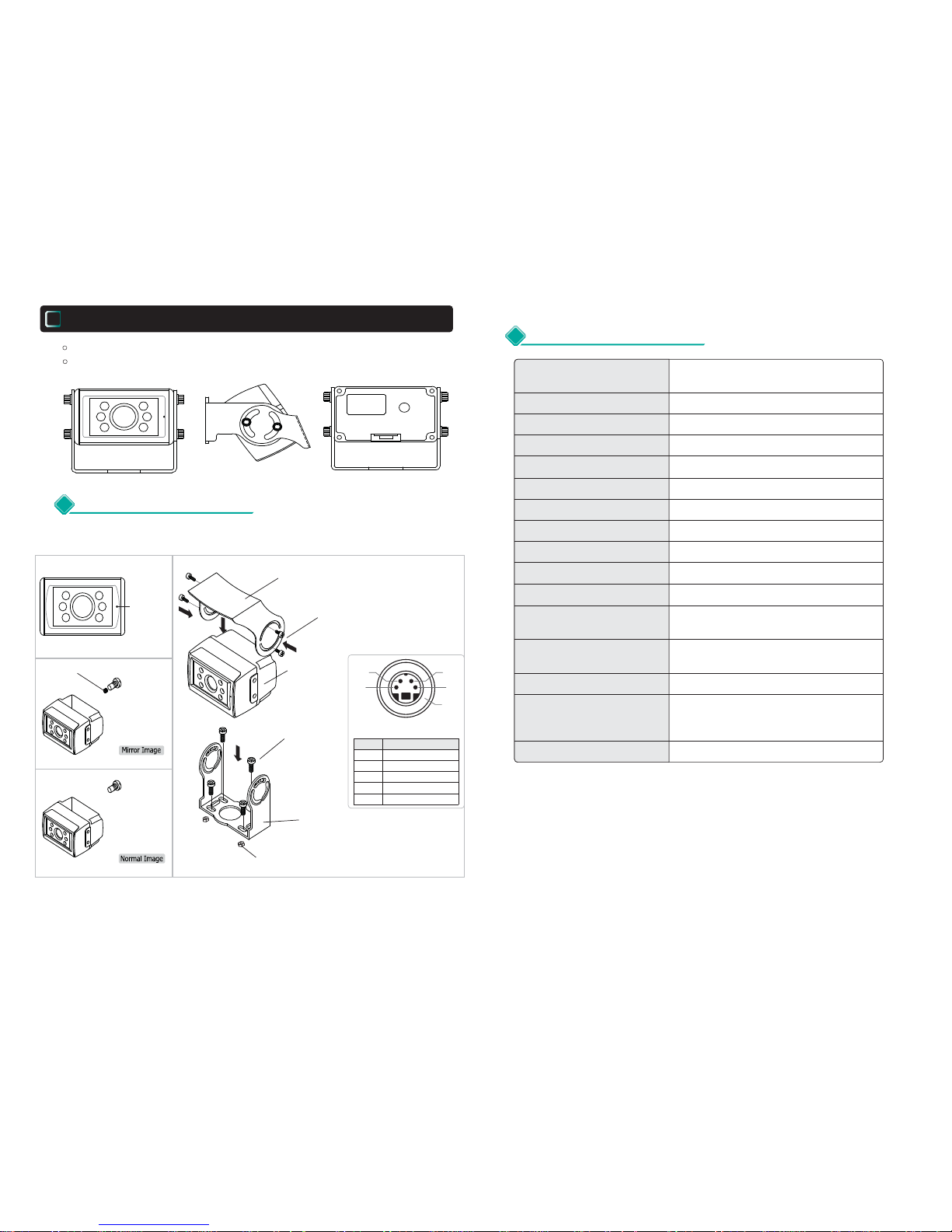
Attach the supplied mounting bracket to vehicle.
Adjust the angle of the camera and fasten the screws firmly.
Waterproof Aluminium Diecasted Low Illumination Color CCD Camera.
Mirror & Normal Image Views
MOUNTING
BRACKET
M4X10 WRENCH
BOLTS 4EA (SEMS)
M4 NYLON NUTS
4EA
M5X15 TP.Or MACHINE
SCREWS 4EA
CAMERA
SUN SHIELD
Microphone
Mikrofon
Microfono
Magnetic (Supplied)
MTB-10C Rear View Camera
VII
1 Features & Installation
4EA
CAMERA CONNECTION
HEATER(OPTIONAL)
DC12V POWER
VIDEO OUTPUT
DESCRIPTION
3
GROUND
5
4
AUDIO
PIN NO.
2
1
1
5
3
4
2
 Loading...