

Page 1

QC Series Generators
OPERATOR’S MANUAL
Issue Date: December 2016
Page 2

TABLE OF CONTENTS
SECTION DESCRIPTION PAGE
1
1.1
2
2.1
2.2
2.3
3
4
4.1
4.2
4.3
5
5.1
5.1.1
5.2
5.3
5.4
5.5
5.6
5.6.1
5.6.2
5.6.3
5.6.4
6
6.1
6.1.1
6.1.2
6.1.3
6.2
6.2.1
6.2.2
6.2.3
6.2.4
6.2.5
6.2.6
7
8
Introduction
Overview
Safety
Safety Alert Symbol And Safety Words
Operational Hazards
Maintenance Hazards
Safety Signs
Assembly
Remove Shipping Dunnage And Par ts
Remove Generator From Pallet
Driveline Dimension
Operation
Preparation For Use
Neutral Bond To Ground
Machine Components
Attaching Generator To Tractor
Detaching Generator From Tractor
Transporting
Operating The Generator
Initial Start-Up
Monitoring The Load
Shutting Down The Generator
Storing The Generator
Service And Maintenance
Service
Electrical Tests
Automatic Voltage Regulator Operational Test
Voltage Regulator Adjustment
Maintenance
Lubrication Symbol
Every 10 Hours
Every 1000 Hours
Severe Service Recommendations
Maintaining The Permanent Magnets
Restoring Residual Magnetism
Troubleshooting
Warranty
............
............
............
............
............
............
............
............
............
............
............
............
............
............
............
............
............
............
............
............
............
............
............
............
............
............
............
............
............
............
............
............
............
............
............
............
............
1
1
2
2
3
6
7
8
8
8
8
10
10
10
10
11
13
13
14
15
16
16
17
18
18
18
19
20
21
22
22
23
23
24
24
25
28
ii
Page 3

1 INTRODUCTION
1.1 Overview
Congratulations on your choice of a Baumalight QC Series Generator. This equipment has been designed
and manufactured to meet the needs of a discriminating buyer for efcient auxiliary power.
The Generator is powered by the Power Take Off (PTO) on your tractor.
Safe, efcient and trouble free operation of your Generator requires that you and anyone else who will
be operating or maintaining the Generator, read and understand the Safety, Operation, Maintenance and
Troubleshooting information contained within the Operator’s Manual.
This manual covers the Baumalight QC Series Generators. Use the Table of Contents as a guide to
locate required information.
Keep this manual handy for frequent reference and to pass on to new operators or owners. Call your
Baumalight dealer, distributor or the factory if you need assistance, information or additional copies of
the manuals.
When this machine is worn out and no longer in use, it should be returned to the retailer or other party
for recycling.
OPERATOR ORIENTATION - The directions left, right, front and rear, as mentioned throughout this
manual, are as seen from the tractor driver’s seat and facing in the direction of travel.
1
Page 4

2 SAFETY
2.1 Safety Alert Symbol
And Safety Words
You must read, understand and follow the
instructions given by the operating unit
manufacturers, as well as the instructions in this
manual.
The safety information in this manual is denoted
by the safety alert symbol:
This symbol means ATTENTION! BECOME
ALERT! YOUR SAFETY IS INVOLVED!
^ CAUTION
CAUTION - Indicates a hazardous
situation, which, if not avoided, could
result in minor or moderate injury.
NOTICE
NOTICE - Indicates a situation that could
result in damage to the equipment or
other property.
The level of risk is indicated by the following signal
words:
^ DANGER
DANGER - Indicates a hazardous
situation, which, if not avoided, WILL
result in death or serious injury.
^ WARNING
WARNING - Indicates a hazardous
situation, which, if not avoided, could
result in death or serious injury.
2
Page 5

2.2 Operational Hazards
^ WARNING
Prevent serious injury or death.
Read and understand this manual before
operating generator.
Never allow anyone near the generator
and tractor during operation.
Travel at a safe speed.
^ WARNING
Prevent serious injury or death from
moving parts.
Moving parts can crush and dismember.
Do not operate without guards and
shields in place.
^ WARNING
Prevent serious injury or death.
Verify generator is hitched to tractor
before operation or transport.
Verify generator driveline is attached to
tractor.
Carefully read all safety messages in this manual
and on equipment safety signs. Keep safety signs
in good condition and replace missing or damaged
safety signs.
New equipment components and repair parts must
include the current safety decal.
Learn how to properly operate equipment.
NEVER operate or work around this equipment
without proper instruction, while fatigued or under
the inuence of alcohol, prescription or non-
prescription medication or if feeling ill.
Disconnect and lock out power source
before adjusting or servicing.
^ WARNING
Use generator only for the designed
applications.
Any other use may result in personal
injury, damage to equipment and may
void the warranty.
Keep your equipment in proper working condition.
Know the regulations and laws that apply to you
and your industry. This manual is not to replace
any regulations or laws. Additional information
may be found at: www.asae.org or www.osha.gov.
If you do not understand any part of this manual,
contact Baumalight at 866-820-7603.
3
Page 6

Prepare For Emergencies
Lower Operating Speed
• Be prepared in case of emergencies.
• Keep a re extinguisher and rst aid kit close
to the machine.
• Keep emergency phone numbers close to your
phone.
• Know your address so emergency services
can locate you if an emergency arises.
Replace Safety Signs
• Replace missing or damaged safety signs.
• Lower operating speed while loading,
unloading or performing heavy operations.
• Keep load low and move at slow speeds on
rough or uneven terrain.
Avoid Rollover
The equipment may rollover, resulting in death or
serious injury. To help prevent rollover:
• Travel at a slow speed.
• Avoid sharp turns & sudden movement on
slopes.
• Avoid holes, ditches and other obstructions
which may cause equipment to rollover.
• Use caution when operating on slopes and do
not operate on excessively steep slopes.
• Safety signs are identied in Section 3 of this
manual.
• Replacement safety signs are available from
your Baumalight dealer.
Do Not Allow Riders
• NEVER carry anyone with generator.
• NEVER use generator as a work platform.
• NEVER allow passengers on generator.
4
^ WARNING
Risk of electrocution. High voltages are
present at the generator’s terminals
when the unit is running.
Additionally, accessory equipment
such as space heaters can be energized
from an outside power source when the
unit is at rest. Be sure to disconnect all
sources of power before working on
equipment.
Page 7

Detach Generator Safely
Detach generator on a rm and level surface.
Generator may roll away if detached on sloping
or soft surface. Be sure people, livestock and pets
are clear of machinery.
Hazards From Modifying
Equipment
Do not make any alterations to your generator.
Altering the equipment may cause unsafe
conditions and may void the manufacturer’s
warranty.
Stay Clear Of Rotating
Drivelines
^ WARNING
Entanglement in a rotating driveline can
cause serious injury or death.
Keep tractor shields and driveline
shields in place at all times. DO NOT
operate without driveline guards.
DO NOT wear loose tting clothing.
5
Page 8

2.3 Maintenance Hazards
Maintenance
Before servicing, park machine on a rm and
level surface, set parking brake, chock wheels,
and place a “Do Not Operate” tag on control
panel. Read and understand this manual. If you
do not understand any part of the manual, contact
Baumalight at 866-820-7603.
Always wear face and/or eye protection, safety
shoes, and other protective equipment appropriate
for the job.
Do not make unauthorized modications. Contact
Baumalight at 866-820-7603 before you weld, cut/
drill holes, or make any other modications.
Always use Baumalight replacement parts.
^ WARNING
Moving parts can crush and cut.
^ WARNING
Entanglement hazard.
Keep clear of moving components.
Wear proper protective equipment
appropriate for the job.
^ WARNING
Burn hazard.
Hot and high pressure hydraulic oil.
Allow oil to cool before servicing.
Keep clear of moving components.
Follow lockout procedure before
servicing.
^ WARNING
Crushing hazard.
Before performing inspections, service
or maintenance:
• Park machine on rm, level surface.
• Engage parking brake.
• Turn engine off and remove key.
• Place “Do Not Operate” tag on
control panel.
6
Page 9

3 SAFETY SIGNS
B. Safety Sign
A. MTB-020 Safety Sign
C. MTB-111 Safety Sign
7
Page 10

4 Assembly
4.1 Remove Shipping
Dunnage And Parts
^ WARNING
Depending on model, approximate
weight of the generator is 269 - 674 kg
(592 - 1485 lbs)
Do not position feet around or under
pallet.
1. Remove crate material from pallet.
2. Remove all shipping bands, wires and loose
parts from around generator.
4.2 Remove Generator
From Pallet
1. Attach hitch to generator frame.
2. Roll generator off of pallet onto oor.
3. Install PTO driveline.
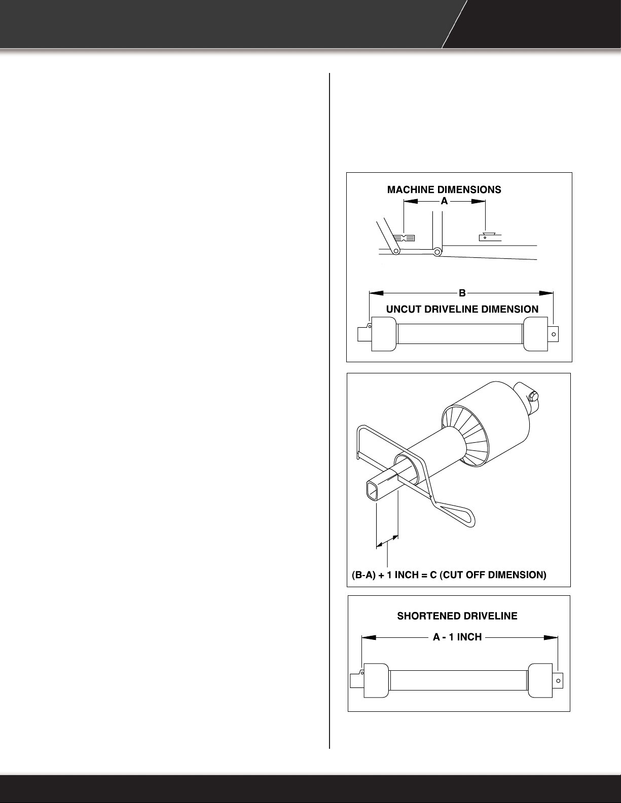
4.3 Driveline Dimension
A PTO driveline is supplied with the machine.
To accompany the variety of hitch geometry
available today, the driveline can be too long for
most machines or too short for others. It is very
important that the driveline be free to telescope
but not to bottom out when going through its
working range. If the driveline bottoms out, the
bearings on both the machine and tractor PTO
shaft will be overloaded and fail in a short time.
1. To determine the proper length of the
driveline, follow this procedure:
a. Clear the area of all bystanders.
b. Attach generator to tractor (see section
5.3) but do not attach driveline.
c. Measure dimension between locking
grooves on tractor PTO shaft and
machine input shaft.
d. Measure the same dimensions on the
compressed driveline.
e. If compressed driveline dimension
exceeds the machine dimension,
driveline will have to be cut.
8
2. When cutting the driveline, follow this
procedure:
a. Subtract machine dimension (A) from
uncut driveline dimension (B) or (B-A).
This dimension determines how much
too long the driveline is.
b. Add another 1 inch (25 mm) to the
dimension to be sure it doesn’t bottom out,
to determine (C) the cut off dimension.
c. Use a hacksaw to cut dimension (C) from
both ends. Cut both plastic tubes and
metal cores.
d. Use a le to remove burrs from edges
that were cut.
e. Assemble the 2 ends of the shaft.
Page 11
f. Make sure shaft can telescope freely. If it
does not, separate the 2 parts and inspect
for burrs or cuttings on shaft ends. Be sure
it telescopes freely before installing.
9
Page 12

5 OPERATION
5.1 Preparation For Use
Although the Generator has been carefully
inspected and checked prior to shipment from
manufacturer, it is recommended that the unit be
thoroughly inspected.
Check all bolts for tightness and remove all
shipping tags, bags, skids, and blocking. Remove
any masking materials afxed during painting.
Inspect the tractor and any accessory equipment
to verify that nameplates and all safety warning,
caution signs and decals provided with the
equipment are in place and clearly visible.
Visually inspect the unit before each start up.
Check for loose or missing parts and any damage
that may have occurred during moving or shipping.
Review all tractor pre-start instructions, and ensure
that all recommended steps and procedures have
been followed.
5.1.1 Neutral Bond To Ground
5.2 Machine Components
A. PTO Driveline
B. Display
C. Power Panel
All units are shipped with neutral bonded to ground
inside alternator. Only a qualied electrician may
relocate neutral bond to a remote location within
electrical service. Electrical connections must
comply with federal, state, provincial and local
electrical codes.
^ WARNING
Prevent injury and machine damage.
Units are shipped with neutral bonded
to ground inside alternator.
Only a qualied electrician may relocate
neutral bond to a remote location within
electrical service.
D. Generator
E. Gear Box
F. PTO Driveline Guard
G. PTO Driveline Support
H. Trailer Tongue
10
Page 13

5.3 Attaching Generator
To Tractor
^ WARNING
To prevent injury or machine damage
put transmission in “Park” and check
for PTO driveline binding or separation.
A
Only experienced and properly trained
operator’s should operate the tractor
and generator.
1. Back up tractor to generator.
2. Engage tractor park brake and/or place
transmission in “Park”.
3. Shut off engine and remove key.
4. Lift up on trailer tongue and slide onto tractor
hitch.
5. Install pin and retaining pin.
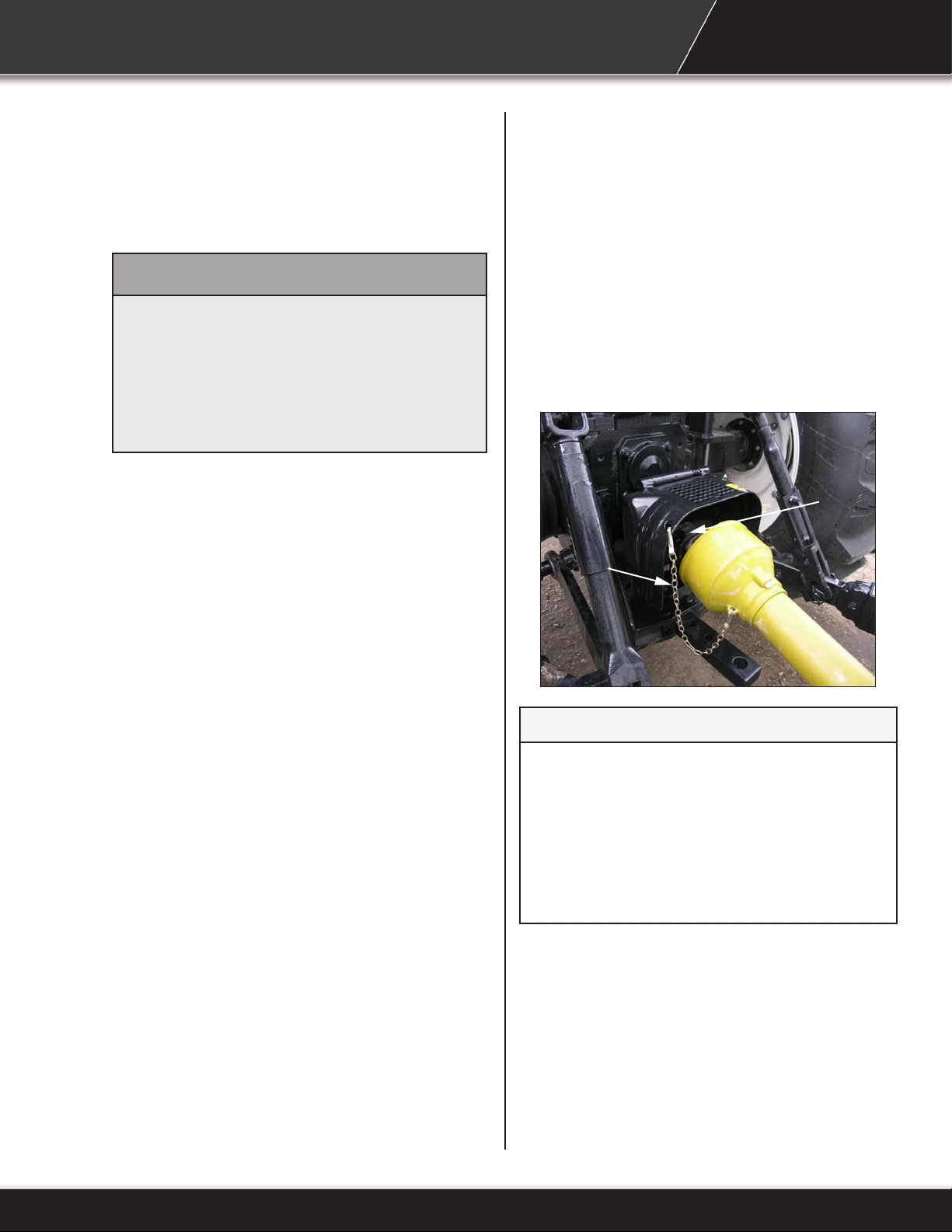
6. Pull collar (A) back toward the generator. Align
splines on tractor PTO shaft and driveline by
rotating generator driveline. Push driveline
onto PTO shaft until it snaps into place.
7. Pull back on driveline to make sure it is locked
on shaft.
8. Attach safety shield chain (B) as shown.
B
NOTICE
A misaligned PTO shaft on the generator
end can cause shuddering and
bouncing on the tires which may lead
to transmission damage and potentially
void the warranty. Be sure PTO shaft
is properly aligned with generator
transmission.
11
Page 14
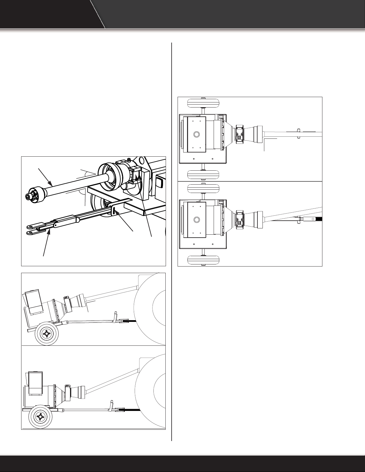
9. If necessary, remove bolt (E) and adjust the
trailer tongue (D) so that the PTO driveline (C) is
perpendicular with the generator transmission
(F). The shaft must be straight with no bend
in the universal joint on the generator side. A
bend is allowable at the tractor’s PTO drive
end.
C
90°
90°
90°
CORRECT
E
INCORRECT
F
D
A misaligned PTO shaft on the generator end can
cause generator to shudder and bounce on the
tires. This may lead to transmission damage and
90°
CORRECT
INCORRECT
potentially void the warranty.
If shaft is straight and generator bounce persists,
reducing generator tire air pressure may help
reduce bouncing.
12
Page 15
5.4 Detaching Generator
From Tractor
^ WARNING
5.5 Transporting
1. Verify all reectors and Slow Moving Vehicle
(SMV) sign are visible.
Prevent serious injury or death caused
by unexpected movement:
1. Park tractor on a level surface.
2. Engage tractor park brake.
3. Disengage PTO.
4. Shut off engine and remove key.
1. Park tractor on a level surface.
2. Shut off engine and remove key.
3. Disconnect driveline safety chain (B).
4. Support driveline with your hand.
5. Pull collar (A) back toward generator and slide
off shaft. Place PTO driveline on driveline
support.
6. Remove retaining pin and pin from trailer
tongue.
7. Lower tongue to ground.
2. Verify trailer tongue is pinned to tractor hitch.
3. Verify tractor PTO is disengaged.
4. Travel at a reasonable and safe speed.
A
B
NOTICE
Do not engage the PTO when towing
the generator to a location or generator
damage could result.
The generator trailer does not have a
suspension. Limit speeds to less than
20 kph (12 mph) to minimize the risk of
rollover.
13
Page 16

5.6 Operating The
Generator
^ WARNING
Entanglement in a rotating driveline can
cause serious injury or death.
Keep tractor shields and driveline
shields in place at all times. DO NOT
operate without driveline guards.
DO NOT wear loose tting clothing.
^ WARNING
Never operate tractor when other people
are in the vicinity.
Do not allow riders on tractor.
^ WARNING
Prevent serious injury or death caused
by unexpected movement:
5.6.1 Initial Start-Up
1. Connect the power cable to the generator and
to the transfer switch.
2. Start the tractor and allow it to warm up.
3. With the engine idling, engage the PTO drive.
4. Adjust throttle until the volts on DisplayMaster1
display 120 VAC (single phase).
5. Turn on the main breaker on the generator.
6. Operate the transfer switch so that the load is
transferred to the generator.
1. Park tractor on a level surface.
2. Engage tractor park brake.
3. Disengage PTO.
4. Shut off engine and remove key.
14
Page 17

15
Page 18

5.6.2 Monitoring The Load
5.6.3 Shutting Down The
Generator
Plan when to change over to generator power.
Ideally, the transfer should take place when the
system demand is at its lowest. If a big motor can
come on stream, change over to generator power
before it does so when the load is lesser.
The generator has sufcient capacity to handle
rush current (higher demand) during motor start
up, so it is permissible to operate temporarily at
overload. However, only allow the generator to do
so for short periods of time (less than a minute).
Carefully monitor the tractor speed settings when
the load changes and adjust the throttle to keep
the generator operating at 120 VAC (single phase).
NOTICE
Risk of generator damage. Avoid running
the generator at overload for excessive
periods of time. Doing so can damage
the generator and void the warranty.
NOTICE
Follow the shut down sequence to
minimize the risk of damage to the
generator or associated equipment.
1. Switch off the electrical load or allow it to drop
to minimum.
2. If possible, operate the transfer switch to
transfer the load back to utility power.
3. Turn generator main breaker off.
4. Drop the tractor speed to idle.
5. Disengage the PTO drive. Allow the PTO shaft
to gradually come to a stop.
6. Shut off tractor engine and remove key.
7. Disconnect the PTO driveline from tractor.
8. Place the mount on the trailer tongue in the
upright position and place PTO driveline on
support.
9. Tow unit back to storage.
10. See Storing Generator in this section if
generator will not be used for some time.
16
Page 19

5.6.4 Storing The Generator
1. Wipe down the unit using a clean rag and
water, or a cleaning solvent.
2. Inspect the air louvers and make sure that they
are not obstructed. The generator requires a
ow of cooling air. Clean them as necessary.
3. With a rag soaked in cleaning solvent, clean
the splines on both ends of the connecting
drive shaft, on the generator driveline, and on
the tractor.
4. Inspect all splines on the driveshaft, the
generator, and the tractor for signs of damage
or wear. Repair any damage or wear as soon
as possible.
5. Apply a light coat of lithium waterproof grease
to the surfaces of the connecting driveshaft
splines.
6. Examine the universal joints for signs of wear
or damage. Repair or replace any worn or
damaged part.
7. Using the grease gun, lubricate each universal
joint.
8. Inspect the level of the lubricant in the gearcase.
Top off as needed with gear lubricant.
9. Verify the tire pressure and adjust as
necessary. Check the sidewall of the tires for
the recommended pressure.
10. Inspect the generator to look for damage to the
generator. If any damage is found, avoid using
the generator and report the damage to your
Baumalight representative.
11. Check all fasteners and make sure they are
properly tightened. This includes the bolts that
attach the generator to the trailer, the bolts that
attach the guard to the gearcase, and the bolts
that attach the tongue to the trailer.
12. Cover generator and store in a clean, dry place.
17
Page 20

6 SERVICE AND
MAINTENANCE
6.1 Service
6.1.1 Electrical Tests
Continuity and Resistance Test
The generator has four components that can be
checked using an ohmmeter:
• Exciter stator
• Exciter rotor
• Main stator
• Main rotor
Each of these components is composed of various
windings forming a complete electrical path of
relatively low resistance. Using an ohmmeter,
measure the loop resistance of each component.
Contact Baumalight for specic values for your
machine.
Note: Very small resistance values require
precision equipment to make accurate
measurements; however, a standard ohmmeter
will provide a good indication of winding continuity.
Diode Testing
Note: Stop tractor engine before performing this
procedure.
5. Repeat the procedure using the other diode
terminal post.
When the positive test probe is connected to
the diode’s anode and the negative test probe is
connected to the diode’s cathode (forward biased),
the diode will switch on and conduct electricity.
This is observed by a low resistance reading when
using an ohmmeter or the lighting of the bulb when
using a battery light continuity tester. Reversing the
test leads (reverse biased) will result in the diode
switching off and no electricity will be conducted.
The results of these tests should indicate one of
three conditions:
Good diode: Will have a much greater resistance
in one direction than the other. Typical reverse
biased resistance will be less than 10 ohms. The
battery light tester will have the light “on” in one
direction and “off” in the other.
Shorted condition: Ohmmeter reading will be zero,
or very low in both directions. The continuity tester
will have light “on” in both directions.
Open condition: Ohmmeter will have a maximum
(innity) reading in both directions. Continuity
tester light will be off in both directions.
1. Remove the two main rotor leads and the threeexciter rotor leads from the rectier assembly.
The rectier assembly is now electrically
isolated from the generator. The diodes remain
mounted and the diode leads remain connected
to the terminal posts.
2. Using an ohmmeter or a battery light continuity
tester, place one test probe on the diode lead
terminal post.
3. In succession, touch the other test probe to the
lead screw hole in each heat sink.
4. Reverse the probes and repeat the procedure.
You have now tested the three diodes connected
to this terminal post in both the forward and
reverse direction.
18
Diode failure after a 25-hour “run-in” period is
generally traceable to external causes such as
a lightning strike, reverse current, line voltage
spikes, and the like. All 6 diodes are essentially in
the same circuit.
Since determining the remaining life on the diodes
when one fails is difcult, replace the entire rectier
assembly, rather than individual diodes, to avoid
possible continued failure.
Page 21

6.1.2 Automatic Voltage
Regulator Operational Test
1. Connect the test setup as shown in Figure 1.
Do not apply power. Insure that the light bulbs
are 120 volts, and less than 100 watts.
2. Adjust the regulator VAR and/or remote VAR
and the STABILITY ADJUST to maximum CCW
3. Apply 240 volts, 50/60 Hz power to the
regulator. The light bulbs should illuminate.
4. Slowly adjust the regulator VAR control CW.
At the regulation point, the light bulbs should
extinguish. Small adjustments above and
below this level should cause the light bulbs to
go off and on. Note that the light bulbs go on
and off rapidly.
5. Rotate the STABILITY ADJUST fully CW. Now
adjust the regulator VAR above and below the
regulation point. The light bulbs should still go
off and on, but the transition from off to on (and
vice versa) should be much slower than in “d”
above.
19
Page 22

6.1.3 Voltage Regulator
Adjustment
Voltage Adjust
The screwdriver adjustable potentiometer adjusts
the generator output voltage. Adjustment clockwise
increases the generator output voltage.
Stability Adjust
System stability is the ability of the generator to
respond to load transients. Decreasing the stability
makes the generator less sluggish and faster to
respond to toad transients. If the stability of the
regulator is decreased too much, the generator will
tend to hunt under steady state conditions.
The screwdriver adjustable potentiometer adjusts
the system stability. Adjustment clockwise
increases the stability. Increasing the stability
increases the response time of the generator.
Conversely, decreasing the stability decreases the
response time of the generator.
V/HZ Roll-Off Frequency Selection
The roll off point is the frequency where the
generator voltage starts to decrease. This reduces
the Kilowatt load to the engine, which allows
the engine to recover in speed under any load
transient condition. Use jumper to select 50 HZ or
60 Hz. The screwdriver adjustable potentiometer
sets the roll-off frequency from 54-61 Hz in the 60
Hz setting or from 45-51 Hz inthe 50 Hz setting.
The SE350 has the roll-off point preset to 58 Hz
in the 60 Hz mode and 48 Hz in the 50 Hzmode.
To change the roll-off point, adjust engine speed
to the desired rated speed. (50 or 60 Hz). Set the
voltage to the desired setting at rated speed. Adjust
engine speed to the desired roll-off point. Turn the
potentiometer counterclockwise until the voltage
starts to drop off. Then adjust the potentiometer
clockwise until the voltage returns to rated voltage.
Re-adjust engine speed to rated speed.
20
Page 23

6.2 Maintenance
Maintenance Chart
General Inspection Inspect the air louvers
and make sure that they
are not obstructed.
Driveline Lubricate U-Joints on
PTO driveline.
Gear Box Oil Change gear box oil.
Use synthetic 75-90W
gear oil.
Daily
Every 250 hours.
Every 1000 hours.
21
Page 24

6.2.1 Lubrication Symbol
6.2.2 Every 250 Hours
Observe lubrication symbol. Lubricate with SAE
multipurpose type grease at hourly intervals.
Lubricate U-joints on PTO driveline every 250
hours of use.
22
Page 25

6.2.3 Every 1000 Hours
6.2.4 Severe Service
Recommendations
1. Park tractor and generator on a level surface.
2. Shut off engine and remove key.
3. Remove drain plug (B).
4. Drain oil and install plug.
5. Remove ll/check plug (A).
6. Add synthetic 75-90W gear oil until oil comes
out of hole.
7. Replace ll/check plug.
Severe service for the QC Series PTO Generator
includes the following:
• More than 100 hours of continuous use in a
month.
• Use outdoors for extended periods in extreme
weather (dust, high heat, cold, or wet weather).
If the QC Series PTO Generator is subject to severe
service, Baumalight recommends thoroughly
cleaning and inspecting the QC Series PTO
Generator. If you suspect that there is damage,
have the QC Series PTO Generator inspected by
your Baumalight representative.
23
Page 26

6.2.5 Maintaining The
Permanent Magnets
If the generator is not used for a long time, it is
possible that the permanent magnets that provide
the magnetic eld for excitation of the eld coil will
lose their magnetism and the generator will not be
able to produce electrical power.
To keep the magnets in good working order, you
must run the generator under load for at least an
hour once every six months.
See Restoring Residual Magnetism in this section,
if your generator loses magnetism.
6.2.6 Restoring Residual
Magnetism
NOTICE
Risk of generator damage. Only attempt
this procedure if you are trained to do
so. If in doubt, contact your Baumalight
representative.
and sensing input, the AVR will go to full
conduction of its power rectier (SCR). With
only 120 volts input power, the AVR will only
force at half of 105 VDC or 52.5 VDC.
3. With 52.5 VDC imposed upon a 24.5 ohm
eld, maximum excitation current will be in the
area of 2.1 to 2.2 amperes, which is 4.5 times
the exciting current imposed on the eld with a
12 VDC ashing source. 2.2 amperes is much
lower than the SE350’s rated continuous
current of 3.5 amperes, thus this procedure
will not pose a threat to the regulator so long
as the exciter eld resistance is 15 Ohms or
higher.
Note: You will need a 120 volt, two prong power
cord with ag terminals crimped on the ends to
perform this procedure.
Place 120 VAC for about 2 to 3 seconds across
SE350 power input terminals #3 & #4 while the
unit was at rest. The basis for this procedure is:
1. The SE350 AVR requires approximately
240 VAC for both input power and sensing
across input terminals #3 and #4. With 240
VAC input, maximum forcing voltage is 105
VDC. Maximum forcing current - for 1 minute
is 5 amperes. Maximum continuous running
current rating of this regulator is 3.5 amperes.
2. MAGNAPLUS exciter elds have a nominal
resistance of 24.5 ohms. With 120 volts AC
(½ rated voltage) imposed on the AVR power
24
Page 27

7 TROUBLESHOOTING
PROBLEM CHECK SOLUTION
High vibration, bouncing or shaking
while running unit.
Display locked up. Tripped fuses. Disconnect power.
Generator produces no voltage. Display off or defective. Check voltage with a separate meter
Generator produces low voltage no
load.
Misaligned PTO shaft - either
vertically or horizontally (gear
box side only).
Defective connections. Verify generator connections. Inspect
Loss of residual magnetism. Flash elds.
Defective diodes, suppressor. Test the generator using the 12 volt
Regulator protection operating. Replace fuse.
Regulator inoperative. Adjust or replace regulator.
Under speed operation. Check speed using a tachometer or
Display off or defective. Check voltage with a separate meter
Incorrect or defective
connections.
Regulator adjustment. Adjust regulator settings. Consult
Defective diodes, suppressor or
windings.
Regulator inoperative. Adjust or replace regulator. Consult
Correctly align PTO shaft horizontally
and vertically (gear box side only).
If shaft is straight, reducing generator
tire air pressure may help reduce
bouncing.
Wait one minute for self-resetting
fuses.
Restart.
Connect load once display shows
correct speed.
at the generator terminals.
all wiring for loose connections, open
circuits, grounds, and short circuits.
battery test or windings as specied
in the testing section. If the results
indicate generator problems, perform
insulation, continuity, and diode tests.
frequency meter.
at the generator terminals.
Verify generator connections (see
drawings supplied with the generator
or lead connection diagrams in this
manual). Inspect all wiring for loose
connections, open circuits, grounds,
and short circuits.
regulator manual.
Test the generator using the 12
volt battery test as specied in the
test section. If the results indicate
generator problems, perform
insulation, continuity, and diode tests.
regulator manual.
25
Page 28

PROBLEM CHECK SOLUTION
Generator produces uctuating
voltage.
Generator produces low voltage
when load applied.
Generator builds voltage from
start-up then goes to low (residual)
voltage.
Generator produces mechanical
noise.
Fluctuating engine speed. Check engine governor systems
for malfunction. Check load for
uctuation.
Regulator stability. Adjust regulator stability.
Defective rectier assembly. Check assembly for loose
connections. Test the diodes.
Loose terminal or load
connections.
Defective regulator. Replace regulator.
Excessive load. Reduce load. The load on each leg
Large motor starting. Motor starting currents are too large
Load power factor. Multiple motors sequence the motors
Driver speed drop. Check driver. Check under frequency
Line drop. If voltage is proper at generator
Defective diodes, suppressor or
windings.
Regulator protective circuit
operating.
Defective bearing. Replace bearing.
Loose or misaligned coupling. Tighten, realign, or replace coupling.
Improve connections both
mechanically and electrically.
should be evenly balanced, and
rated current should not be exceeded
on any leg.
for the generator when starting.
and start the largest motor rst.
Reduce lagging power factor load.
setting on regulator Under frequency
voltage roll-off may be activated.
terminals but low at the terminals,
Increase external wire size.
Test the generator using the 12
volt battery test as specied in the
test section. If the results indicate
generator problems. See continuity,
and diode tests.
Check indicators on regulator.
Correct problems and adjust
regulator as is required. Refer to
regulator manual.
26
Page 29

PROBLEM CHECK SOLUTION
Generator produces high voltage. Faulty metering. Check voltage with a separate meter
at Anderson connectors.
Incorrect connections. Verify generator connections.
Regulator requires adjustment. Adjust regulator settings. Consult
regulator manual.
Leading power factor. Check power factor of the load. If
power factor is leading, change load
conguration. Excessive leading
power factor (capacitors) can cause
voltage to climb out of control.
Defective regulator. Replace regulator.
Generator is overheating. Generator is overloaded. Reduce load. Check with amps on
display and compare with nameplate
rating.
Clogged ventilation screens. Clean air passages.
High room temperature. Improve ventilation or reduce load or
altitude.
Equipment runs normally on utility
power, but will not run on generator
set.
Insufcient circulation of cooling
air.
Unbalanced load. The load on each leg should be as
Distorted voltage waveform. Analyze load. Excessive SVR
Improper generator voltage. Check nameplates of devices
Generator location and enclosure
design must provide adequate air
ow and minimize recalculation.
evenly balanced as possible and
should not exceed rated current on
any one leg.
(thyristor) loading will cause
distortion. Some equipment may be
sensitive to distorted waveforms.
Contact Baumalight.
comprising the load.
Compare required or frequency
voltage and frequency with that of
the generator.
Adjust driver speed and/or
generator voltage as necessary
to match generator output to load
requirements.
27
Page 30

8 WARRANTY
This product is warranted to be free of defects in materials and workmanship under normal use and
service, for a period of one year from the date of purchase, when operated and maintained in accordance
with the Operating and Maintenance Instructions supplied with this unit. This warranty does not cover
misuse or negligence.
Under no circumstances will the manufacturer be liable for any consequential damage or expense of any
kind, including loss of prots. The manufacturer is under no circumstances liable for tractor damage of
any kind. The manufacturer is not liable for the maintenance of the product.
This warranty is extended only to the original purchaser. Warranty is void if repairs are attempted by
anyone other than an Authorized Service Center.
If a difculty develops with the product, you should contact your nearest Authorized Repair Centre, or
distributor. Only these locations are authorized to make repairs to the product or affect the replacement of
defective parts, which will be done at no charge within a reasonable time after the receipt of the product.
Units or parts should be returned at the customer’s expense to the nearest repair location or Authorized
Service Centre. Pack unit in a strong carton and pad tightly to avoid damage. Damage in-transit is not
covered by warranty. Include original purchase receipt with any claim (keeping a copy for your les).
The Manufacturer’s Liability is limited to repair of the product and/or replacement of parts and is given to
the purchaser in lieu of all other remedies including incidental and consequential charges. There are no
warranties, expressed or implied other than those specied herein. For the nearest Authorized Service
Centre call the manufacturer.
Please note the following details and le this information in an appropriate place.
Model Number: ___________ S/N:_______________
Date of Purchase: _____________ Owner’s Name__________________________________
28
Page 31

29
Page 32

30
MTB MFG INC.
CORPORATE HEADQUARTERS
4575 Powell Rd.,
Wallenstein, Ontario Canada
N0B 2S0
Phone - 519.698.9864
Toll Free - 866.820.7603
Fax - 519.698.1087
www.baumalight.com
 Loading...