

MTA TAEevo Tech 101, TAEevo Tech 051, TAEevo Tech 081, TAEevo Tech 020, TAEevo Tech 121 Operating And Maintenance Manual
...
TAEevo Tech
WATER CHILLERS
OPERATING AND MAINTENANCE MANUAL
TAEevo Tech 015÷802 60 Hz UL
DDOMA00417
Original instructions in Italian language (Service)

OPERATING AND MAINTENANCE MANUAL
- User’s quick guide
TAEevo Tech 015÷802 60 Hz UL
1
The data in this manual are not binding and they can be modified by the manufacturer without notice. Reproduction of this manual is strictly prohibited
EN
ENGLISH
USER’S QUICK GUIDE
ATTENTION
MODIFICATION OF AN UL LISTED PRODUCT
MTA chillers feature an electrical cabinet designed and wired in compliance with the UL508A standard for electrical
enclosures. The UL compliance allows this MTA equipment to meet local code requirements in most locations in the US and
Canada. When a UL Listed product is modified, retrofitted or altered in any way after it leaves the factory, it is necessary to
verify if the product continues to meet the applicable certification safety requirements.
If a modification made to the product in the field (outside of the MTA factory) does NOT affect the electrical characteristics
of the panel installed on the machine, then the UL Listing is not affected and th e UL label that was placed on the p roduct at
the factory can remain. Some examples include:
- Making the remote ON / OFF connection (to terminals provided in the panel)
- Making the alarm relay connection (to terminals provided in the panel)
- Making remote terminal connection (to terminals provided in the panel)
- Replacement of panel components with equal components
If a modification made in the field DOES affect the electrical characteristics of the panel installed on the machine, it is not
possible for UL to confirm that the product continues to meet the applicable certification safety requirements. In this case
the field modifications must be specifically inspected and recertified by the appropriate UL agency. Some examples include:
- Replacement of panel components with components that are different than those originally supplied
- Replacement of motors (or other current-drawing devices) that involve the change of components inside the panel
- Addition of devices not provided for by MTA
- Addition of electrical loads not foreseen by MTA
In this case it is the responsibility of the AUTHORITY HAVING JURISDICTION to assess the acceptability of modifications
and/or to determine if modifications are significant enough to require a member of the UL field engineering services staff to
evaluate and/or recertify the modified product. Anyone directly involved with a product (including manufacturers, owners,
contractors, and regulatory authorities) can request a Field Evaluation.
For further clarification, contact MTA USA or visit the UL’s Web site at www.ul.com/field.
ATTENTION
Before starting units of this type, ensure that all personnel inv olved have read and understood Chapter 2 “Safety” and
follow the procedures set down in Chapter 6 “Starting”.
ATTENTION
When first starting after a stop of several days, ensure that the casing heating element of each compressor is switched
on for at least 12 hours before pressing the start button.
ATTENTION
The pressure l imiting valve is factory set, according to the pump nominal flow operating at a standard voltage of 460V/
3Ph/60Hz.
Before using the unit it is necessary to set the limiting valve according to the plant nominal flow and accordin g to the power
supply.
Units in the TAEevo Tech range are equipped with an electronic controller that manages correct operation of the appliance on
the basis of signals read on the analogue and digital inputs.
This quick guide contains a list of the main functions of the electronic board. For more detailed information consult Chapter7
“Electronic controller”.

OPERATING AND MAINTENANCE MANUAL
- User’s quick guide
TAEevo Tech 015÷802 60 Hz UL
2
The data in this manual are not binding and they can be modified by the manufacturer without notice. Reproduction of this manual is strictly prohibited
ENGLISH
EN
On the models TAEevo Tech 015÷351 the electronic control unit is installed on the door of the electrical panel, while on
models TAEevo Tech 381÷802 it is fitted inside the electrical panel while the door is equipped with LCD graphic display.
NOTE
To convert the semi-graphic LCD display on the door of the electrical panel (mod. TAEevo Tech 381÷802) to remote control,
the relevant remote control kit must be ordered.
0.1 Unit start/stop
The unit can be switched on and off as follows:
• From the keypad (local or remote)
• From a digital input configured as remote ON/OFF
NOTE
In case of a power loss, when pow er is restored the unit will be ON if it was ON at the time of power loss, and OFF if it was
OFF.
0.1.1 Start from the keypad
From unit OFF (stand-by) press and release button to switch the unit on or off in chiller mode. With the unit on LED
is lit.
Stand-by mode is set each time the unit is switched off from chiller operating mode. Also in stand-by the controller makes it
possible to:
• Display the measured values.
• Manage the alarm situation by displaying and signalling active alarms.
When the unit is in stand-by the controller shows the label
on the display.
Electronic control TAEevo Tech 015÷351
LCD graphic display TAEevo Tech 381÷802

OPERATING AND MAINTENANCE MANUAL
- User’s quick guide
TAEevo Tech 015÷802 60 Hz UL
3
The data in this manual are not binding and they can be modified by the manufacturer without notice. Reproduction of this manual is strictly prohibited
EN
ENGLISH
0.1.2 Start-up from a digital input
The unit can be switched on/off from a digital input configured as remote On/OFF.
The power-off command (local or remote) always assumes priority with respect to the power-on command. If the unit is
powered-off with a local command it must be powered back on with a local command.
When the unit is in OFF status from a digital input the controller shows the label
. on the display.
For details concerning the connection, refer to the electrical diagram.
0.2 Setpoint
0.2.1 Display the setpoint
To display the setpoint press and release the key.
With the unit in stand-by the lower display will show SetC (chiller set).
The upper display will show the set value.
0.2.2 Change the setpoint
To change the unit working setpoint press the key for at least 3 seconds and the working setpoint SetC (chiller set) will
appear in flashing mode.
The setpoint can be changed using the or buttons.
To save the new setpoint, press or wait for the time-out to exit programming mode.
0.3 Alarms display and reset
ATTENTION
With this procedure you can reset all the alarms except for the compressor thermal cut-out alarms for which the
password will be required: 14.
To open the functions menu proceed as follows:
• Open the functions menu by pressing the button
• With the or buttons select the ALrM function
•Press .
If no alarms are present, pressing button is not enabled.
• The lower display shows the label with the alarm code; the upper display, if the alarm displayed is resettable,
shows the label rSt or no if the alarm condition is still present.
• Pressing in correspondence with label rSt resets the alarm and the system goes to the next one; if this too
is resettable, press to reset it and go to the next one.
• If you want to scroll through all the alarms present press or .
To exit the ALrM function and return to normal display mode press or wait for the time-out.
With the unit in StbY (stand-by) and the LED flashing, press and scroll with buttons or to select the ALrM
function and press button to display the active alarm.
NOTE
To reset the compressor thermal alarms refer to the specific heading.

OPERATING AND MAINTENANCE MANUAL
- Table of Contents
TAEevo Tech 015÷802 60 Hz UL
4
The data in this manual are not binding and they can be modified by the manufacturer without notice. Reproduction of this manual is strictly prohibited
ENGLISH
EN
TABLE OF CONTENTS
USER’S QUICK GUIDE .........................................................................................................................1
0.1 Unit start/stop....................................................................................................................2
0.1.1 Start from the keypad ..........................................................................................................2
0.1.2 Start-up from a digital input ................................................................................................3
0.2 Setpoint .............................................................................................................................3
0.2.1 Display the setpoint ............................................................................................................. 3
0.2.2 Change the setpoint .............................................................................................................3
0.3 Alarms display and reset................................................... ........................................... ..... 3
TABLE OF CONTENTS.........................................................................................................................4
Chapter 1
GENERAL INFORMATION....................................................................................................................8
1.1 How to interpret the model ...............................................................................................9
1.2 How to interpret the alphanum eric strin g .......................................................................10
Chapter 2
SAFETY..............................................................................................................................................11
2.1 General............................................................................................................................11
2.2 User circuit liquids....................................................... ................................................... 11
2.3 Lifting and transport precautions.................................................................................... 11
2.4 Precautions to be adopted during installation ................................................................. 13
2.5 Precautions to be adopted during operation.................................................................... 13
2.6 Maintenance precautions ................................................................................................ 13
2.7 Disposal, disassembly and recycling .............................................................................. 15
2.8 Refrigerant gases....................................................................................................... ...... 15
2.8.1 Refrigerants safety datasheet ............................................................................................15
Chapter 3
TECHNICAL DATA.............................................................................................................................17
3.1 Data for standard units....................................................................................................17
3.1.1 Dimensions ...................................... ..................................................................................17
3.1.2 Characteristics of pumps and fans .................................................................................... 18
3.1.3 Sound level measurements .................................................................................................18
Chapter 4
DESCRIPTION....................................................................................................................................20
4.1 Components .................................................................................................................... 20
4.1.1 Refrigerant circuit .............................................................................................................20
4.2 Compressors.................................................................................................................... 20
4.3 Condenser ....................................................................................................................... 20
4.4 Evaporator....................................................................................................................... 21
4.5 Tank ................................................................................................................................ 21
4.6 Pump ...............................................................................................................................21
4.7 Fans.................................................................................................................................21
4.7.1 Axial ...................................... ......... ...... ......... ....... ......... ....... ......... ........ ....... ....... ...............21
4.8 Cabinet............................................................................................................................ 22
4.9 Materials in contact with the liquid to be cooled............................................................ 22
4.10 Overall dimensions and minimum clearances with respect to walls..............................22
4.11 Electrical circuit..............................................................................................................22
Chapter 5
INSTALLATION..................................................................................................................................23
5.1 Inspection........................................................................................................................23
5.2 Location .......................................................................................................................... 23
5.3 Freeze protection ............................................................................................................. 24
5.3.1 Operating limits ............. ................................................................... ................................. 24
5.4 Hydraulic connections .................................................................................................... 25
5.4.1 Evaporator water limit features ...................... .................................................................. 27
5.5 Expansion vessel.............................................................................................................27
5.6 Electrical connections..................................................................................................... 28

OPERATING AND MAINTENANCE MANUAL
- Table of Contents
TAEevo Tech 015÷802 60 Hz UL
5
The data in this manual are not binding and they can be modified by the manufacturer without notice. Reproduction of this manual is strictly prohibited
EN
ENGLISH
5.7 Phase Monitor ............................................. ....................................................................29
Chapter 6
STARTING..........................................................................................................................................30
Chapter 7
ELECTRONIC CONTROLLER ............................................................................................................. 32
7.1 User interface ..................................................................................................................32
7.2 Function of buttons .........................................................................................................32
7.2.1 Function of combined buttons ......................................................... ...................................33
7.3 Remote terminal..............................................................................................................33
7.4 Probes key .......................................................................................................................33
7.5 Unit start/stop..................................................................................................................34
7.5.1 Start from the keypad .........................................................................................................34
7.5.2 Start from a digital input ...... .............................................................................................34
7.6 Setpoint ........................................................................................................................... 34
7.6.1 Display the setpoint ............ ................................... ............................................................34
7.6.2 Change the setpoint ...........................................................................................................34
7.7 Dynamic setpoint function ..............................................................................................35
7.8 How to display the internal values of a circuit................................................................36
7.9 Functions menu button “Menu”......................................................................................36
7.9.1 CrEn - Enable or disable the single circuit .......................................................................36
7.9.2 COEn - Enable or disable the single compressor ..............................................................37
7.9.3 COSn - Display and reset the number of compressor starts ..............................................37
7.9.4 Hour - Display and reset the running hours of the loads ..................................................37
7.9.5 Cond - Display of percentage / number of condensing steps ............................................38
7.9.6 POEn - ENABLE or DISABLE the operation of a water pump using the key ...................38
7.10 uS - Tank heater probe display........................................................................................38
7.11 Alarms.............................................................................................................................39
7.11.1 Alarms display and reset (ALrM function) ........................................................................39
7.11.2 How to mute the buzzer ........... ...........................................................................................39
7.11.3 General alarms list ........................................................................... .................................39
7.11.4 Indications table . .. ..................................................................... ........................................41
7.11.5 Probe faulty .................... ....................................................................................................41
7.11.6 High pressure switch alarm ...............................................................................................41
7.11.7 High pressure switch alarm and/or compressor thermal alarm ........................................42
7.11.8 Low pressure switch alarm ....... .................................... .....................................................42
7.11.9 High pressure .....................................................................................................................43
7.11.10Low pressure ......................................................................................................................43
7.11.11Anti-freeze alarm ...............................................................................................................44
7.11.12Chiller mode anti-freeze alarm ..........................................................................................44
7.11.13Level sensor and/or flow meter alarm ...............................................................................44
7.11.14Compressors thermal alarm ..............................................................................................46
7.11.15Fan thermal alarm .............................................................................................................46
7.11.16High condensing pressure unloading indication in chiller mode ......................................47
7.11.17High condensing pressure recovery disabling indication .................................................47
7.11.18Evaporator inlet high water temperature unloading indication ........... .............................48
7.11.19Evaporator water pump group thermal alarm ..................................................................48
7.11.20Phase monito r alarm ................................................................................... ......................49
7.11.21Compressors maintenance alarm ......................................................................................49
7.11.22Pumps maintenance alarm .................................................................................................49
7.11.23EEprom alarm ....................................................................................................................49
7.11.24Unit configuration alarm ...................................................................................................50
7.12 iCHILL input/output configurations ...............................................................................52
7.12.1 Configuration of analogue inputs PB1 - PB2 – PB5 – PB6 ..............................................52
7.12.2 Configuration of analogue inputs PB3 - PB4 ....................................................................52
7.12.3 Configuration of digital inputs ID1 – ID11 .......................................................................53
7.12.4 Configuration of digital outputs RL1- RL8 ................................ ........................................54
7.12.5 Configuration of proportional outputs OUT1 and OUT2 (0 – 10 VOLT) .........................55
7.12.6 Configuration of proportional outputs OUT3 and OUT4 (0 – 10 VOLT/PWM) ...............55
7.12.7 Display in programming mode of polarity of digital inputs / outputs ...............................56
7.12.8 Remote terminal alarm ......................................................................................................56
7.12.9 Remote terminal alarm ......................................................................................................56
7.12.10Alarm relay / open - collector / buzzer notes ............................. .................................... ....56
7.12.11Diagnostic of alarms that switch from automatic to manual .............................................57

OPERATING AND MAINTENANCE MANUAL
- Table of Contents
TAEevo Tech 015÷802 60 Hz UL
6
The data in this manual are not binding and they can be modified by the manufacturer without notice. Reproduction of this manual is strictly prohibited
ENGLISH
EN
7.12.12Display and delete the alarms log in the memory (ALOG function) ........... ......................57
7.13 Programming from keypad............................................................................................. 57
7.13.1 Access to parameters ....................... ..................................................................... .............58
7.13.2 How to change a parameter value ....................................................................................59
7.14 Use of the hot-key (function UPL) .................................................................................59
7.14.1 Programming the board with the hot-key ..........................................................................59
7.14.2 Hot-key programming ....................................................................................................... 59
7.15 Unit adjustment and control............................................................................................59
7.15.1 Compressors control ...................................................................... ............................... ....59
7.15.2 Choice of compressors control type .................................................................................. 59
7.15.3 Proportional control .......................................................................................................... 59
7.15.4 Compressors proportional control diagram .....................................................................60
7.15.5 Neutral zone control (factory setting) ............................................................................... 60
7.15.6 Compressors rotation ................................... .................................. ...................................60
7.15.7 Forced compressors rotation ......................................... .. .................................... .............60
7.15.8 Compressors starting time limitation ................................................................................ 61
7.16 Unloading function ......................................................................................................... 61
7.17 Fans control........................................................................................ ... ..........................61
7.17.1 Units configured with “STEP” fans ................................................... ............................... 61
7.17.2 Fan control diagrams ........................................................................................................ 61
7.18 Hydraulic unit ................................................................................................................. 61
7.19 Anti-freeze pump management (if ambient probe is installed) ...................................... 61
7.20 ModBus...........................................................................................................................62
7.21 Automatic restart.............................................................................................................62
7.22 Control with LCD graphic display..................................................................................6 2
7.23 Function of buttons.........................................................................................................63
7.24 Probes visualization........................................................................................................63
7.25 Unit start/stop.................................................................................................................. 63
7.25.1 Start from the keypad ........................................................................................................64
7.25.2 Start-up from a digital input ..............................................................................................64
7.26 Visualization / modification of the set point...................................................................64
7.27 Alarm visualization.................................. .......................................... .............................64
7.28 Menu service visualization .............................................................................................65
7.29 Parameters programming................................................................................................ 65
7.30 Compressor maintenance................................................................................................ 66
7.31 Water pump maintenance ...............................................................................................66
7.32 Circuit maintenance........................................................................................................67
7.33 Alarm visualization and reset ......................................................................................... 67
7.34 Alarm log visualization................................................................... ................................68
7.35 Electric heater visualization............................................................................................ 68
7.36 I/O status......................................................................................................................... 68
7.37 Auxiliary output visualization ........................................................................................69
7.38 Parameters programming with Hot Key.........................................................................70
7.39 Keyboard configuration.................................................................................................. 71
7.40 Circuit Information .........................................................................................................71
7.41 Parameters description-settings ...................................................................................... 73
7.41.1 Description of parameters .................................................................................................73
7.41.2 Parameters setting ...........................................................................................................105
7.41.3 Parameters dependent on remote terminal kit ................................................................ 181
Chapter 8
OTHER COMPONENTS.....................................................................................................................182
8.1 Compressor motor protection ....................................................................................... 182
8.2 Refrigerant high and low pressure switches .................................................................182
8.3 Fan pressure switches ................................................................................................... 182
8.4 Pressure transducers.................................... .......................................... ........................183
8.5 Level sensor .................................................................................................................. 183
Chapter 9
OPERATION AND MAINTENANCE ...................................................................................................184
9.1 Operation ......................................................................................................................184
9.2 Maintenance....................................................... ........................................... ...............184
9.3 Access to the unit..........................................................................................................184

OPERATING AND MAINTENANCE MANUAL
- Table of Contents
TAEevo Tech 015÷802 60 Hz UL
7
The data in this manual are not binding and they can be modified by the manufacturer without notice. Reproduction of this manual is strictly prohibited
EN
ENGLISH
9.4 Draining the process water circuit.................................................................................185
9.5 Pressure limiting valve (option)....................................................................................186
9.5.1 General notes of safety ....................................................................................................186
9.5.2 General notes ............................... ....................................................................................186
9.5.3 Range of application ........................................................................................................186
9.5.4 Installation and assembly ........................................................ .. .................................... ..186
9.5.5 Setting ..............................................................................................................................187
9.5.6 Operating and maintenance .............................................................................................187
9.5.7 Warranty ................................. ................................................. ........................................187
9.5.8 Marking ................................... ............. .............. ............. ........... .............. ............. ...........187
9.6 Maintenance Schedule...................................................................................................188
Chapter 10
TROUBLESHOOTING........................................................................................................................189
Chapter 11
RISK ANALYSIS: RESIDUAL RISK....................................................................................................194
OPERATING AND MAINTENANCE MANUAL
Chapter 1 - General information
TAEevo Tech 015÷802 60 Hz UL
8
The data in this manual are not binding and they can be modified by the manufacturer without notice. Reproduction of this manual is strictly prohibited
ENGLISH
EN
CHAPTER 1
GENERAL INFORMATION
The units described in this manual may be referred to below as “WATER CHILLERS”.
This manual is addressed to personnel responsible for installing, using and servicing the unit.
The units were constructed using components made by premium quality manufacturers and the entire design, production and
control process was carried out in compliance with standard ISO 9001.
In the majority of applications the liquid in the user circuit is water so henceforth the term “WATER” will be utilised, even if
the liquid in the user service is different (for example mixtures of water and ethylene or propylene glycol).
Hereinafter the expression “PRESSURE” is used to indicate relative pressure.
The electrical panel has been designed following UL508A standard rule (Industrial Control Panels).
The compressors and fans carry the cURus marking.
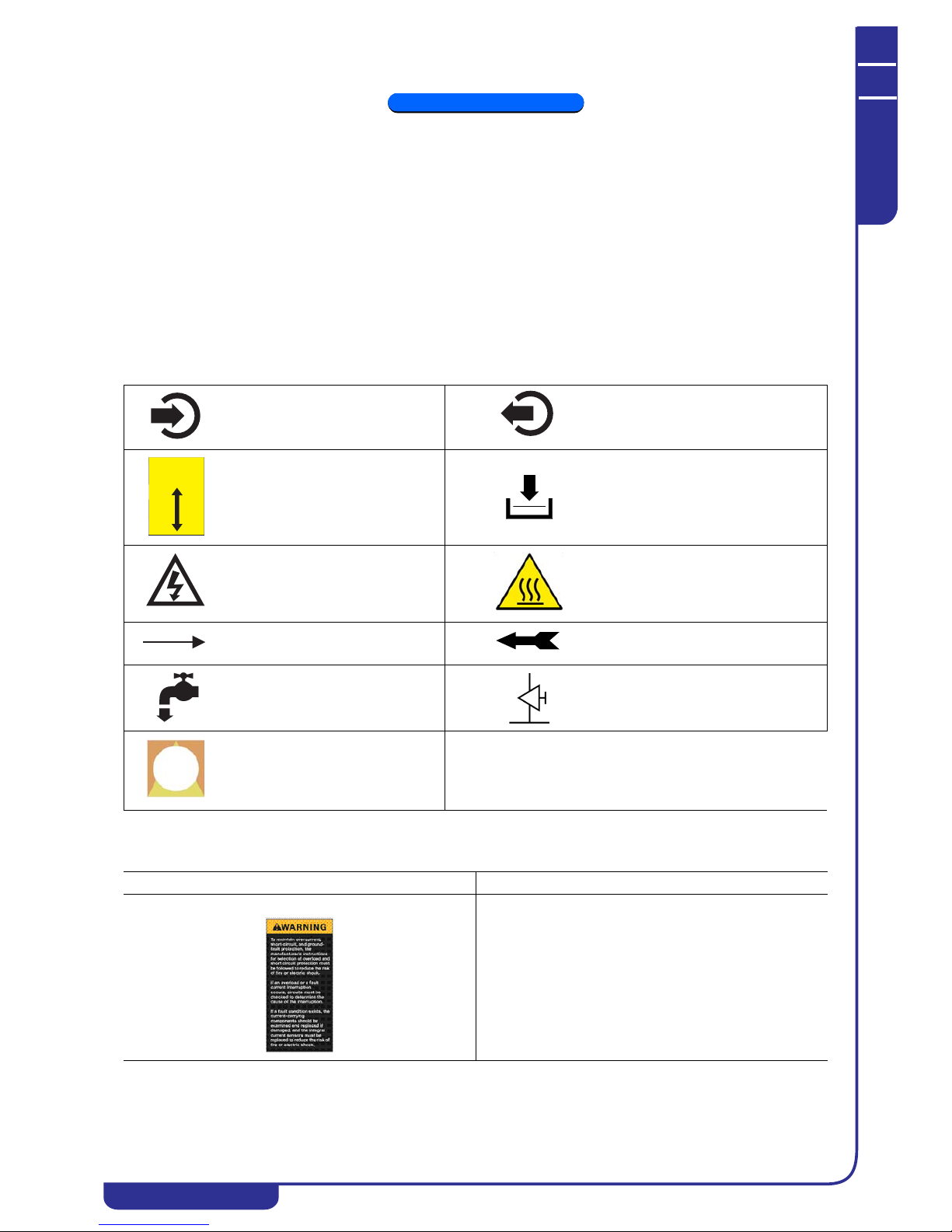
The following symbols are to be found on the decals affixed to the unit and also in the dimensional drawings and refrigerant
circuit diagrams.
The meaning of each symbol is indicated below:
The following warning symbols are shown on the stickers on the unit. If requested, the same stickers are available also in
French. Their meaning is the following:
Process water inlet Process water outlet
Indication of the axis of reference for
lifting operations
Drain point to empty the unit of water
Electric shock hazard
Risk of burns from contact with hightemperature surfaces
Direction of flow of refrigerant fluid
and water circuit
Rotation direction of pump (if installed)
and fans
Water filling point Air bleed valve
Opening to be used for the insertion
of bars for the purpose of lifting the
unit
WARNING SYMBOL DESCRIPTION
To maintain overcurrent, short-circuit, and ground-fault
protection, the manufacturer’s instructions for selection of
overload and short circuit protection must be followed to
reduce the risk of fire or electric shock.
In an overload or a fault current interruption occurs, circuits
must be checked to determine the cause of the interruption.
If a fault condition exists, the current-carrying components
should be examined and replaced if damaged, and the
integral current sensors must be replaced to reduce the risk
of fire or electric shock.
ASSE DI SOLLEVAMENTO
AXIS OF EQUILIBRIUM
GLEICHGEWICHTSACHSE
EMPLACEMENT DE FORCHES
PUNTO DE ELEVACION

OPERATING AND MAINTENANCE MANUAL
Chapter 1 - General information
TAEevo Tech 015÷802 60 Hz UL
9
The data in this manual are not binding and they can be modified by the manufacturer without notice. Reproduction of this manual is strictly prohibited
EN
ENGLISH
1.1 How to interpret the model
ATTENTION
This manual, which is addressed to users, installers, and service personnel, supplies all the technical information
required to install and work with the unit and to perform the routine maintenance operations required to maximise its
working life.
Use only genuine parts when carrying out routine maintenance or repairs.
Requests for SPARE PARTS and any INFORMATION concerning the unit must be made to your dealer or nearest service
centre, specifying the MODEL and SERIAL NUMBER shown on the unit’s dataplate and on the last page of this manual.
Hazardous voltage.
All doors must be closed before energizing the panel.
Read and understand operator’s manual before using this
machine.
Failure to follow operating instructions could result in death
or serious injury.
Moving parts can crush and cut.
Do not operate with guard removed.
Follow lockout procedure before servicing.
Hazardous voltage.
Disconnect power before servicing or cleaning.
MODEL DESCRIPTION
Number of refrigerant circuits
Guideline power of compressor expressed in HP
E = hermetic compressor
A = air-cooled condenser
T = tank; chiller with storage tank.
WARNING SYMBOL DESCRIPTION
TAEevo Tech XX Y

OPERATING AND MAINTENANCE MANUAL
Chapter 1 - General information
TAEevo Tech 015÷802 60 Hz UL
10
The data in this manual are not binding and they can be modified by the manufacturer without notice. Reproduction of this manual is strictly prohibited
ENGLISH
EN
1.2 How to interpret the alphanumeric string
The alphanumeric string is shown on the metal data plate on the cover page of this manual.
This symbol shown alongside appears in some refrigerant circuit diagrams and electrical
diagrams. This symbol refers to the alphanumeric string reported in the manual. The upper
box (X) identifies the position of the string, the lower box (Y) identifies the assigned value.
The empty alphanumerical string is circled in the adjacent figure; each
position in the upper row is associated with an alphanumeric value in the
lower row (0, 1, 2, A, B, etc.) and each character is associated with a
specific feature of the unit.
POS. VALUE DESCRIPTION
REFRIGERANTE 1 3 R410A
VOLTAGE 2 0 400/3/50
1 460/3/60
N 400/460/3/50-60
UNIT AMBIENT TEMPERATURE 3 0 STANDARD
1 -20°C
COMPRESSOR START-UP 4 0 DIRECT
2 SOFT STARTER
EVAP. FREEZE PROTECTION 5 0 NO
1YES
VERSION 6 STD STANDARD
ELECTRONIC THERMOSTATIC
VALVE
07 NO
1YES
LASER 8 A YES
BNO
C TEMPERATURE FINE REGULATION
FAN 9 A AXIAL
B CENTRIFUGAL
G HIGH PRESSURE AXIAL FLOW FANS
FAN CONTROL 10 1 ELECTRONIC CONTROL
3 ON/OFF
PRE-PAINTED CONDENSING COILS 11 0 NO
1YES
PUMP
13
R SP - Predisposed P3
IP3
LP5
PP3+P3
QP5+P5
TANK MATERIAL
14
1 Fe+Fe
2 Aisi+NoF
WATER BYPASS
15
1 OVERLOAD VALVE
2NO
KIT TYPE
16
A NO KIT
B TANK KIT
PRODUCT TYPE
1
7
0 STANDARD
X SPECIAL
0
1
12
CONDENSER COIL PROTECTION
NONE
FILTERS

OPERATING AND MAINTENANCE MANUAL
Chapter 2 - Safety
TAEevo Tech 015÷802 60 Hz UL
11
The data in this manual are not binding and they can be modified by the manufacturer without notice. Reproduction of this manual is strictly prohibited
EN
ENGLISH
CHAPTER 2
SAFETY
This unit is designed to ensure the best guarantees of safety and efficiency in its intended use, on the condition that it is
installed, commissioned, and serviced in compliance with the instructions given in this manual.
The manual must therefore be studied by all those who want to install, use or maintain the unit.
The unit contains electrical components that operate at mains voltage and also moving parts.
All work on the unit must be carried out only after disconnecting the electrical supply. Maintenance operations involving
work inside the unit must be performed by skilled and adequately qualified perso nnel equipped with suitable pr otection
means (active and passive, e.g. work gloves) to ensure maximum safety.
Keep unauthorized persons (e.g. children) away from the place of installation of the unit.
2.1 General
When handling or maintaining the unit and all auxiliary equipment, personnel must operate with care observing all
instructions concerning health and safety at the installation site.
ATTENTION
Numerous accidents that occur during operation and maintenance of the units are caused by failure to comply with
basic safety rules and precautions.
An accident can often be avoided by recognising a situation that is potentially hazardous.
The user must ensure that all personnel involved in operating and servicing the unit have read and understood all the
warnings, precautions, prohibitions and notes given in this manual and affixed to the unit. Improper operation or maintenance
of the unit and auxiliary equipment can be dangerous and can cause serious or fatal accidents.
We cannot anticipate every possible circumstance which might constitute a potential hazard.
The warnings in this manual are therefore not all-inclusive.
If the user adopts operational procedures or uses tools or working procedures that are not specifically recommended, he must
take care to ensure that the unit and the auxiliary equipment are not damaged or made unsafe and that no risks emerge in
relation to persons or property. Any improper use of the unit will relieve the manufacturer from any liability for possible
personal injury or property damage.
Arbitrary modifications made to the unit will automatically invalidate all forms of guarantee provided by the manufacturer.
ATTENTION
The hot / chilled water prod uced by units canno t be used for hygiene/sanitary or food applications. If it is
used for the above purposes, the installer must install an intermediate exchanger.
If the intermediate exchanger is not present, the installer must affix a warning notice to the eff ect “non potable
water”.
2.2 User circuit liquids
The user circuit liquids must be compatible with the materials used for the construction of the unit’s hydraulic circuit.
The expression “liquids” means: water, water with additives and/or glycol. Additive and glycol suppliers must guarantee
compatibility with the materials. For further information refer to “4.9 Materials in contact with the liquid to be cooled”.
ATTENTION
If the liqui ds in the user circuit contain hazardous substances (such as glycol, for example), any liquid that is expelled
from a leakage area must be collected because it is noxious for the environment. The disposal of hazardous liquids must be
handled by specialised companies authorised for the treatment of hazardous wastes.
2.3 Lifting and transport precautions
Avoid injury by using a hoist to lift heavy loads.
Check all chains, hooks, shackles and slings are in good condition and are of the correct capacity.
They must be tested and approved according to local safety regulations.
Cables, chains or ropes must never be attached directly to lifting eyes.
Always use an appropriate shackle or hook properly positioned. Arrange lifting cables so that there are no sharp bends.
Use a spreader bar to avoid lateral loading of hooks and eyebolts.
When a load is lifted from the ground keep well clear of the area beneath the load and the immediately surrounding area.

OPERATING AND MAINTENANCE MANUAL
Chapter 2 - Safety
TAEevo Tech 015÷802 60 Hz UL
12
The data in this manual are not binding and they can be modified by the manufacturer without notice. Reproduction of this manual is strictly prohibited
ENGLISH
EN
Keep lifting acceleration and speed well within safety limits and never leave a suspended load attached t o a hoist any longer
than strictly necessary. The weight values shown in the following table were obtained with the unit empty, pump P3and axial
fans.
The manufacturer does not supply load spreaders, lifting straps or hooks with the unit.
Model TAEevo Tech 402÷602
Model TAEevo Tech 015 020 031 051 081 101 121 161 201 251
Weight (kg) 144 149 208 2 31 341 385 399 415 595 678
Weight (lb) 317 328 459 5 09 752 849 880 915 1312 1495
Model TAEevo Tech 301 351 381 401 402 502 602 702 802
Weight (kg) 711 722 995 1080 1197 1246 1282 1585 1605
Weight (lb) 1567 1592 2194 2381 2639 2747 2826 3494 3538
Model TAEevo Tech 015÷161 Model TAEevo Tech 201÷401

OPERATING AND MAINTENANCE MANUAL
Chapter 2 - Safety
TAEevo Tech 015÷802 60 Hz UL
13
The data in this manual are not binding and they can be modified by the manufacturer without notice. Reproduction of this manual is strictly prohibited
EN
ENGLISH
Model TAEevo Tech 702÷802
NOTE
Weight values are guideline, with the water circuit empty. The values may vary in relation to the configuration of the unit
(pump type, supply type, and ventilation type).
2.4 Precautions to be adopted during installation
The connections to be prearranged concern the process water circuit. For connection to the mains electrical supply consult
the technical documentation attached to the unit.
2.5 Precautions to be adopted during operation
The unit must be operated by competent personnel under the guidance of a qualified supervisor.
All water pipelines must be painted or clearly marked in compliance with local safety prescriptions in force in the place of
installation.
ATTENTION
Do no t remove or tamper with safety devices, protections, or the insulating materials installed in the unit and in the
auxiliary equipment.
All electrical connections must comply with local codes.
The unit and its auxiliary equipment must be connected to earth and protected against short circuits and overloads.
When mains power is switched on, lethal voltages are present in the electrical circuits and extreme caution must be exercised
if any work must be carried out on the electrical system.
Do not open the electrical equipment guard panels while the circuit is energized. Operations that require intervention with the
electrical circuit energized must be performed only by qualified personnel using appropriate equipment and wearing apparel
and devices designed to protect against electrical hazards.
2.6 Maintenance precautions
ATTENTION
When it is necessary to discharge waste material do not pollute water pipelines, groundwater or watercourses.
Avoid the combustion of materials that could produce fumes that are toxic and harmful when released into the atmosphere.
Protect the environment by using only approved methods of disposal.
Keep a written record of all work carried out on the unit and the auxiliary equipment. The frequency and the nature of the
work required over a period can reveal adverse operating conditions that should be corrected.
4OOKP

OPERATING AND MAINTENANCE MANUAL
Chapter 2 - Safety
TAEevo Tech 015÷802 60 Hz UL
14
The data in this manual are not binding and they can be modified by the manufacturer without notice. Reproduction of this manual is strictly prohibited
ENGLISH
EN
ATTENTION
Use only the refrigerant specified on the data pl ate of the unit.
Make sure that all instructions concerning operation and maintenance are strictly followed and that the complete unit, with all
accessories and safety devices, is kept in good working order. The accuracy of pressure and temperature gauges must be
regularly checked. If values are discovered that exceed the permissible tolerances, the gauges must be replaced.
ATTENTION
Do not perform weldin g procedures or other operations that can produce heat in the vicinity of elements containing oil
or flammable liquids. Systems which may contain oil or flammable liqui ds must be completely purged and cleaned, e.g. w ith
steam, before carrying out such operations.
Components in the vicinity must be protected with non-inflammable material and, if the operation is to be performed close to
parts of the lubrication system or in the vicinity of components that may contain oil or inflammable liquids, the system must
first be purged.
Never use an open flame as a light source to inspect parts of the unit.
For all units establish a suitable time interval for cleaning procedures.
ATTENTION
If replacement parts are needed use only original spares.
Take care not to damage pressure limiting devices.
All guards must be refitted after carrying out repair or maintenance work.
ATTENTION
Check the direction of rotation of the motors (the pump, if installed) when starting the unit for the first time and after
work has been performed on the electrical connections or on the power supply sectioning device.
Do not use flammable liquids to clean the unit when it is running. If chlorinated hydrocarbon non-flammable fluids are used
for cleaning, safety precautions must be taken against any toxic vapours that may be released.
ATTENTION
Before removing any panels or dismantling any part of the unit, carry out the following operations:
- Isolate the unit from the electrical power supply by disconnecting the supply upstream of the power feeding line.
- Lock out the disconnect switch in the “OFF” position by fitting a padlock.
- Affix a tag to the disconnect switch handle stating “WORK IN PROGRESS - DO NOT SWITCH ON”.
- Do not set the electrical power switch to ON or attempt to start the unit if it has been tagged out with a warning sign.
Coloured tracers can be used in service-maintenance operations.
Inspect all refrigerant circuit unions including connectors, flanges, and more generally all critical po ints (open unions) in
order to prevent possible leakage of refrigerant gas.

OPERATING AND MAINTENANCE MANUAL
Chapter 2 - Safety
TAEevo Tech 015÷802 60 Hz UL
15
The data in this manual are not binding and they can be modified by the manufacturer without notice. Reproduction of this manual is strictly prohibited
EN
ENGLISH
2.7 Disposal, disassembly and recycling
The product was designed and built with recyclable materials.
The correct waste sorting for the subsequent start-up of the equipment disposed of for recycling, treatment and for
compatible environmental disposal, contributes to prevent possible negative consequences on the environment and health. It
also favour the recycling of the materials the equipment is made up with.
The unit may include all or some of the materials listed below:
• Refrigerant fluid R410A
• Copper parts
• Aluminium parts
• Carbon Steel parts
• Stainless Steel parts
•PVC parts
• CFC-free synthetic insulating material
• polystyrene parts
• Polyester oil
•Brass
During dismantling, the compressor, pumps, fans, exchangers (if working) can be recovered for possible re-use thanks to
specialised centres.All materials must be recycled or disposed of in compliance with the corresponding national regulations.
Refrigerant, oil and possible anti-freeze solutions recycling must be done by specialised companies in compliance with the
corresponding local and national legislation.
Electrical and electronic materials cannot not be disposed of together with domestic general waste. They must be disposed of
in special collection centres.
Units must be treated at a centre specialised in re-conditioning, recycling and recovery of materials.
2.8 Refrigerant gases
The units are charged with R410A refrigerant
Do not replace or mix one gas with another because different gases are not mutually compatible.
To clean out a very heavily contaminated refrigerant system, e.g. after a refrigerant compressor burnout, a qualified
refrigeration engineer must be consulted to carry out the task.
The manufacturer’s instructions and local safety regulations should always be observed when handling and storing high
pressure gas cylinders.
2.8.1 Refrigerants safety datasheet
Denomination: R410A (50% Difluoromethane (R32); 50% Pentafluoroethane (R125)).
INDICATION OF HAZARDS
Major hazards: Suffocation.
Specific hazards: Rapid evaporation can cause frostbite.
FIRST AID MEASURES
General information: Do not attempt to administer liquids or solids to persons who have lost consciousness.
Inhalation: Move victims to the open air. Use oxygen or artificial respiration if necessary.
Do not administer adrenaline or similar substances.
Contact with the eyes: Wash thoroughly with plenty of clean water for at least 15 minutes and seek medical
assistance.
Contact with the skin: Wash immediately in plenty of clean water. Remove contaminated clothing immediately.
FIRE-FIGHTING MEASURES
Means of extinction: Any.
Specific hazards: Pressure rise.
Specific methods: Cool containers with water spray.
MEASURES IN THE EVENT OF ACCIDENTAL LEAKAGE
Individual precautions: Evacuate personnel to safe muster points. Provide adequate ventilation. Use personal
protective equipment.
Environmental precautions: Evaporates.
Cleaning methods: Evaporates.
HANDLING AND STORAGE
Handling
Technical measures/ precautions: Ensure the presence of sufficient ventilation and/or air extraction means in the
workplace.
Recommendations for safe use: Do not breath fumes or aerosol.
Storage: Close hermetically and store in a cool, dry and well-ventilated place. Store in its original
containers. Incompatible products: explosives, flammable materials, organic peroxide

OPERATING AND MAINTENANCE MANUAL
Chapter 2 - Safety
TAEevo Tech 015÷802 60 Hz UL
16
The data in this manual are not binding and they can be modified by the manufacturer without notice. Reproduction of this manual is strictly prohibited
ENGLISH
EN
CONTROL OF EXPOSURE/INDIVIDUAL PROTECTION
Control parameters: AEL (8-h and 12-h TWA) = 1000 ml/m3 for each of the two components.
Respiratory protection: For rescue and maintenance work in tanks use autonomous breathing apparatus. The
vapours are heavier than air and can cause suffocation, by reducing the oxygen available
for breathing.
Protection of the eyes: Safety spectacles.
Protection of the hands: Rubber gloves.
Hygiene measures: Do not smoke.
PHYSICAL AND CHEMICAL PROPERTIES
Colour: Colourless.
Odour: Faint.
Boiling point: -52.8°C at atmospheric pressure.
Flash point: Non-flammable.
Relative density: 1.08 kg/l at 25°C.
Solubility in water: Negligible.
STABILITY AND REACTIVITY
Stability: No reactivity if used in compliance with instructions.
Materials to avoid: Highly oxidising materials. Incompatible with magnesium, zinc, sodium, potassi um and
aluminium.
Incompatibility is more critical if the metal is present in the form of powder or if surfaces
have been recently unprotected.
Hazardous decomposition
products:
These products are halogen compounds, hydrofluoric acid, carbon monoxides (CO,
CO2), carbonyl halides.
TOXICOLOGICAL INFORMATION
Acute toxicity: (R32) LC50/inhalation/4 hours/lab. rats 760 ml/l
(R125) LC50/inhalation/4 hours/lab. rats 3480 mg/l
Local effects: Concentrations significantly above the TLV can cause narcotic effects.
Inhalation of products in decomposition can lead to respiratory difficulty (pulmonary
oedema).
Long-term toxicity: No carcinogenic, teratogenic, or mutagenic effects observed in laboratory animals.
ECOLOGICAL INFORMATION
Global warming potential GWP
(R11=1):
1730
Ozone depletion potential ODP
(R11=1):
0
Considerations on disposal: Usable with reconditioning.

OPERATING AND MAINTENANCE MANUAL
Chapter 3 - Technical data
TAEevo Tech 015÷802 60 Hz UL
17
The data in this manual are not binding and they can be modified by the manufacturer without notice. Reproduction of this manual is strictly prohibited
EN
ENGLISH
CHAPTER 3
TECHNICAL DATA
The data plate affixed to the unit bears the following technical data:
ATTENTION
The performance of the unit depends mainly on the flow rate and temperature of water in the user circuit, and the
condenser thermal exchange fluid temperature. These values are defined at the time of the offer.
3.1 Data for standard units
3.1.1 Dimensions
See attached drawings.
MODEL and CODE The mode l number and the code identify the size of the unit and the type of
construction.
MANUAL Code number of the manual.
SERIAL NUMBER Construction number of the unit.
MANUFACTURING YEAR Year of unit’s final testing.
VOLTAGE/PHASE/FREQUENCY Electrical power supply characteristics.
MAX CURRENT DRAW (I max) Unit current draw in limit operating conditions.
SHORT CIRCUIT CURRENT Short circuit current.
HIGHER MOTOR FLA Max. absorbed current.
INSTALLED POWER (P max) Unit power input in limit operating conditions
PROTECTION RATING According to European standard EN 60529 / NEMA 250 international standard.
ELECTRICAL DIAGRAM Identifies the electrical diagram number.
REFRIGERANT Refrigerant fluid in the unit.
REFRIGERANT QUANTITY Quantity of refrigerant fluid contained in the unit.
USER CIRC. FLUID Type of user fluid utilised by the unit (normally water)
MAX ALLOWABLE PRESSURE (PS) Max. design p ressure of the user circuit.
ALLOWABLE TEMPERATURE (TS) Minimum and maximum values of temperature of the user circuit; this should not be
confused with the maximum working temperature which is established when the
offer is made.
CONDENSER COOLING FLUID Fluid used by the unit to cool the condenser.
MAX WORKING PRESSURE Max. design pressure of the condenser cooling circuit (this data is not present if the
unit is air cooled condensed).
MAX. TEMPERATURE Condenser cooling circuit maximum design temperature (this information is not
given if the unit’s condenser is air-cooled).
SOUND PRESSURE LEVEL Free field sound pressure level in hemispherical radiation conditions (open field) at
a distance of 1 m from the condenser side of the unit and a height of 1.6 m from the
ground.
AMBIENT TEMPERATURE Minimum and maximum values of ambient air temperature.
WEIGHT Approximate weight of the unit before packing.
OPERATING AND MAINTENANCE MANUAL
Chapter 3 - Technical data
TAEevo Tech 015÷802 60 Hz UL
18
The data in this manual are not binding and they can be modified by the manufacturer without notice. Reproduction of this manual is strictly prohibited
ENGLISH
EN
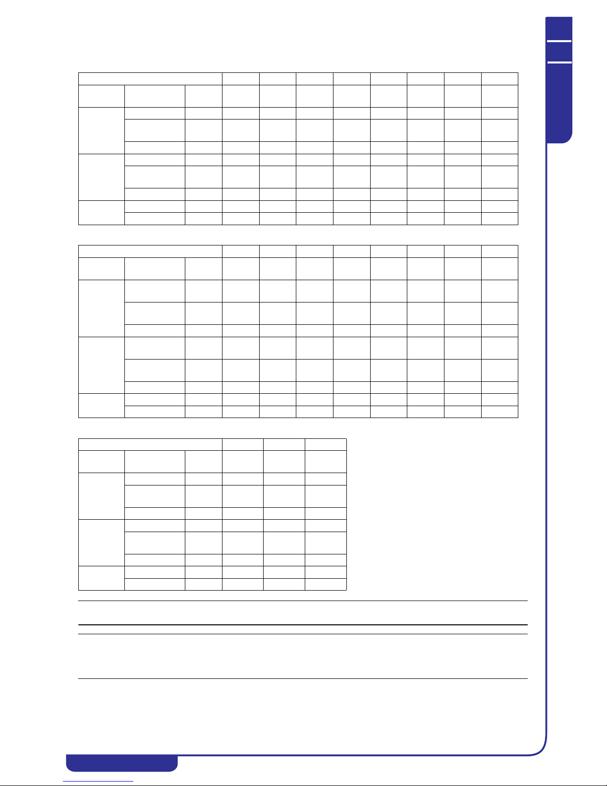
3.1.2 Characteristics of pumps and fans
NOTE
The values in the table may vary in relation to the unit model and configuration. In this case refer to the offer data.
NOTE
The pressure head is the pressure head available in the user’s premises. The installed pump my differ with respect to the
standard pump. For the flow rate and pressure head values two numbers are specified: the first refers to nomin al conditions
and the second refers to maximum conditions.
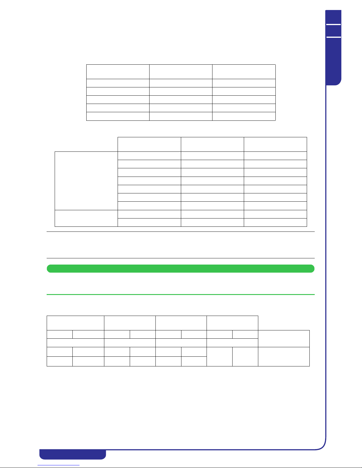
3.1.3 Sound level measurements
Model TAEevo Tech 015 020 031 051 081 101 121 161
Tank
capacity
water volume (gal) 16 16 30 30 37 67 67 67
Pump P3
water flow rate (gpm) 2.0/21.1 2.0/21.1 3.8/21.1 4.8/21.1 9.5/42.3 12.1/42.3 15.2/85.4 18.0/85.4
pump pressure
head
(PSI) 44.9/25.4 44.9/25.4 44.1/28.7 43.7/29.9 4 3.1/22.2 42.4/25.8 42.5/23.4 42.3/24.4
rated power (kW) 0.75 0.75 0.75 0.75 0.9 0.9 1,85 1,85
Pump P5
water flow rate (gpm) 2.0/26.4 2.0/26.4 3.8/26.4 4.8/26.4 9.5/66.0 12.1/66.0 15.2/66.0 18.0/66.0
pump pressure
head
(PSI) 85.7/44.9 85.7/44.9 84.3/50.6 83.4/49.2 8 7.5/50.1 86.6/56.9 85.4/56.9 84.2/57.5
rated power (kW) 1.5 1.5 1.5 1.5 3.0 3.0 3.0 3.0
Axial flow
fan
No. of fans 11111222
total airflow (cfm) 2795 2470 4530 3590 5825 9945 9415 9415
Model TAEevo Tech 201 251 301 351 381 401 402 502
Tank
capacity
water volume (gal) 92.5 92.5 92.5 92.5 108 108 1 32 132
Pump P3
water flow rate (gpm) 19.0/84.5 19.0/84.5
26.5/
105.7
30.9/
105.7
39.5/
220.1
43.9/
220.1
37.9/
220.1
37.9/
220.1
pump pressure
head
(PSI) 42.4/28.9 42.4/28.9 45.9/19.3 45.2/18.5 5 2.2/20.4 52.1/20.4 52.4/25.0 52.4/25.0
rated power (kW) 1.8 1.8 2.2 2.2 4 4 4 4
Pump P5
water flow rate (gal)
19.0/105.7 19.0/105.7
26.5/
105.7
30.9/
105.7
39.5/
220.1
43.9/
220.1
37.9/
220.1
37.9/
220.1
pump pressure
head
(PSI) 75.6/47.7 75.6/47.7 74.8/47.8 74.0/47.0 7 7.6/42.9 77.2/42.9 77.7/47.6 77.7/47.6
rated power (kW) 4 4 4 4 7.5 7.5 7.5 7.5
Axial flow
fan
No. of fans 22332222
total airflow (cfm) 1 1535 11415 15625 15625 2 5662 24367 25895 25070
Model TAEevo Tech 602 702 802
Tank
capacity
water volume (gal) 132 179 179
Pump P3
water flow rate (gpm) 37.9/220.1 69.2/220.1 81.3/220.1
pump pressure
head
(PSI) 52.4/25.0 62.7/36.0 61.4/36.0
rated power (kW) 4 5.5 5.5
Pump P5
water flow rate (gal) 37.9/220.1 69.2/378.6 81.3/378.6
pump pressure
head
(PSI) 77.7/47.6 70.0/30.9 69.7/30.9
rated power (kW) 7.5 11.0 11.0
Axial flow
fan
No. of fans 2 3 3
total airflow (cfm) 24 285 43967 42378
OPERATING AND MAINTENANCE MANUAL
Chapter 3 - Technical data
TAEevo Tech 015÷802 60 Hz UL
19
The data in this manual are not binding and they can be modified by the manufacturer without notice. Reproduction of this manual is strictly prohibited
EN
ENGLISH
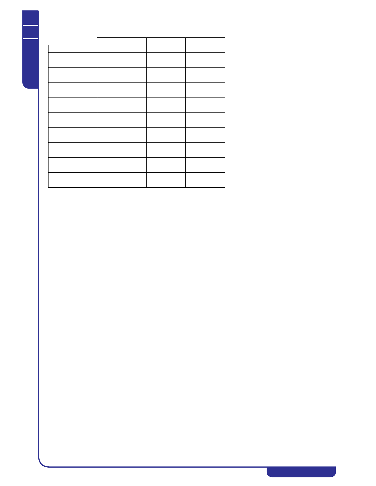
* at distance of 1 m (3.2 FT)
** global
Test conditions
Noise levels refer to operation of the unit at full load in nominal conditions.
Sound pressure level in hemispherical irradiation conditions at a distance of 1 m (3.2 FT) from the condensers side of the unit
and height of 1.6 m (5.2 FT) from the ground. Values with tolerance of ± 2 dB.
Sound pressure level: according to ISO 3744.
Fan Lp dB(A) * Lw dB(A) **
TAEevo Tech 015 axial 69,5 82,5
TAEevo Tech 020 axial 68,9 81,9
TAEevo Tech 031 axial 69,6 82,6
TAEevo Tech 051 axial 70,7 83,7
TAEevo Tech 081 axial 70,9 83,9
TAEevo Tech 101 axial 72,0 85,0
TAEevo Tech 121 axial 71,2 84,2
TAEevo Tech 161 axial 72,1 85,1
TAEevo Tech 201 axial 74,2 87,2
TAEevo Tech 251 axial 74,1 87,1
TAEevo Tech 301 axial 75,6 88,6
TAEevo Tech 351 axial 75,3 88,3
TAEevo Tech 381 axial 78.0 91,0
TAEevo Tech 401 axial 80.2 93,2
TAEevo Tech 402 axial 79,5 92,5
TAEevo Tech 502 axial 79,6 92,6
TAEevo Tech 602 axial 79,3 92,3
TAEevo Tech 702 axial 79.4 92,4
TAEevo Tech 802 axial 80.6 93,6

OPERATING AND MAINTENANCE MANUAL
Chapter 4 - Description
TAEevo Tech 015÷802 60 Hz UL
20
The data in this manual are not binding and they can be modified by the manufacturer without notice. Reproduction of this manual is strictly prohibited
ENGLISH
EN
CHAPTER 4
DESCRIPTION
4.1 Components
Data for materials are referred to standard units. Non-standard materials may be utilised in order to meet specific
requirements. In this case refer to the offer data.
The units are basically composed of the following parts:
• Refrigerant compressor
• Condenser
• Evaporator
•Tank
•Pump
• Frame/cabinet
• Electronic controller
4.1.1 Refrigerant circuit
TAEevo Tech 015÷401 models feature a single refrigerant circuit with one or two compressors connected in parallel
(tandem).
TAEevo Tech 402÷802 models feature two refrigerant circuits with two compressors connected in parallel (tandem).
Each refrigerant circuit, is equipped with the following components:
• refrigerant fluid utilised R410A;
• hermetic scroll compressor;
• pressure switch for fans with On/Off control (only TAEevo Tech 015÷401);
• high and low refrigerant pressure switches;
• high pressure transducer for fan speed control and for unloading (modes TAEevo Tech 402÷802);
• thermostatic lamination valve complete with external pressure equalizer;
• filter dryer;
• liquid sight-glass;
• refrigerant pressure gauges (from TAEevo Tech 031);
• schrader service valves.
For more information consult the attached diagrams.
4.2 Compressors
The compressors are of the SCROLL type and are characterised by high energy efficiency, low vibration and consequent very
low noise during normal operation.
The compressors are cooled by the refrigerant on the suction line, protected against possible overheating of the windings by
an internal module that monitors windings temperature, and protected upline by thermal magnetic cutouts. These components
are housed in an enclosed compartment, but they are readily accessible.
NOTE
During the short periods of starting and stopping the compressor you may hear a metallic noise due respectively to the initial
contact between the coils and to the momentary reversal of their rotation. This noise is absolutely normal and does not affect
the reliability of the compressor.
ATTENTION
At the time of the first start following a prolonged stoppage lasting several days, ensure the crankcase heater of each
compressor is switched on at least 12 hours before pressing the start button.
NOTE
TAEevo Tech 402÷802 units can be optionally fitted with compressor stating with a Soft Starter.
The Soft Starter is linked to each compressor and it serves to limit peak current at the time of compressor starting.
- Units equipped with soft starters can operate up to a maximum ambien t temperature of 40°C, beyond which the unit simply
stops, without tripping any alarms.
- The soft starters are not compatible with capacitive devices (e.g. power factor correction capacitors) installed between the
soft starter and the compressor motor. Any static or dynamic power factor correction systems installed upline from the main
power circuit breaker must not operate simultaneously with staring of the soft starter.
4.3 Condenser
Condensation occurs in finned core coils composed of copper tubes and headers, corrugated aluminium fins, and galvanized
sheet metal shoulders.

OPERATING AND MAINTENANCE MANUAL
Chapter 4 - Description
TAEevo Tech 015÷802 60 Hz UL
21
The data in this manual are not binding and they can be modified by the manufacturer without notice. Reproduction of this manual is strictly prohibited
EN
ENGLISH
4.4 Evaporator
The evaporator is of the finned core type; water flows in contact with the finned surface at velocities such as to ensure low
pressure drops, while the refrigerant flows through the tubes.
In these models the exchanger is protected from the risk of ice formation caused by low evaporation temperatures, with antifreeze strategies handled by the electronic controller. The evaporator water outlet temperature is controlled by a probe. If
negative room/water temperatures are required, a mixture of water and glycol must be used.
To drain the circuit refer to “9.4 Draining the process water circuit”.
4.5 Tank
The storage tank is cylindrical.
The tank can be protected against freezing by means of an electric heater managed by the electronic controller. A level sensor
in the tank serves to signal low water level conditions. The standard supply includes anti-condensation cladding, a drain
valve and an air bleed valve.
An internal bypass between the water delivery and return connections makes it possible to read the anti-freeze probe if the
unit’s process water inlet and outlet connections are inadvertently closed. In this case the unit stops due to tripping of the
anti-freeze alarm and the shut-off valves must be reopened.
The bypass serves exclusively to allow an anti-freeze alarm to trip (if present) and to allow the pump to run with a reduced
water flow rate without damage. It is advisable to avoid repeated anti-freeze alarm trip cycles in the foregoing conditions.
4.6 Pump
The unit is equipped with centrifugal pumps that can be of two different types, characterised by their ability to provide
different pressure heads depending on requirements (3 and 5 barg / 43.5 and 7 2.5 PSI pump). The unit can also be su pplied
without an installed pump. The electrical characteristics of the compatible pump are specified in the wiring diagram.
The pump seals are in silicon carbide/silicon carbide/EPDM.
ATTENTION
Bleed the circuit by unscrewing the bleed cap on the pump whenever the hydraulic circuit is filled. See 5.4 “Hydraulic
connections”.
NOTE
The pump must never run dry.
4.7 Fans
4.7.1 Axial
The fans are of the axial flow type, comprising a diecast aluminium fan wheel with sickle shaped blades.
The protection rating of the fans is IP54.
All fans feature insulation class F to ensure they are compatible with outdoor operation in all climates. Fan assembly is
completed by an upper safety grille (supporting the fan).
For models TAEevo Tech 031÷802 it is possible to fit a semi-transparent
container kit, secured to the rear of the unit. In steady state conditions the
water level in the container must be approximately at the half-way point. In
this case water filling is performed via the container kit.
OPERATING AND MAINTENANCE MANUAL
Chapter 4 - Description
TAEevo Tech 015÷802 60 Hz UL
22
The data in this manual are not binding and they can be modified by the manufacturer without notice. Reproduction of this manual is strictly prohibited
ENGLISH
EN
4.8 Cabinet
The entire plinth, the uprights, and the outer panels are made of galvanized carbon steel sheet and are assembled by means of
screws and/or rivets. All panels undergo phosphor degreasing treatment followed by ep oxy polyester power coating.
The frame is designed to allow easy access to all components of the unit.
4.9 Materials in contact with the liquid to be cooled
Standard chillers: carbon steel, copper, aluminium, zinc, brass, stainless steel and plastic materials
specifically:
• evaporator with copper tubes, aluminium fins and galvanized sheet metal shoulders;
• carbon steel tank.
Chillers with non-ferrous hydraulic circuit (TAEevo Tech 015÷401): stainless steel (AISI 304), copper, brass and plastic
materials.
Specifically:
• with copper tubes and fins and brass shoulders;
• tank in AISI 304 stainless steel.
The pump mechanical seals are in silicon carbide/silicon carbide/EPDM.
4.10 Overall dimensions and minimum clearances with
respect to walls
See the enclosed electrical diagrams.
4.11 Electrical circuit
Refer to Chapter 5 “Installation” for information on electrical hook-ups and consult the attached diagrams.
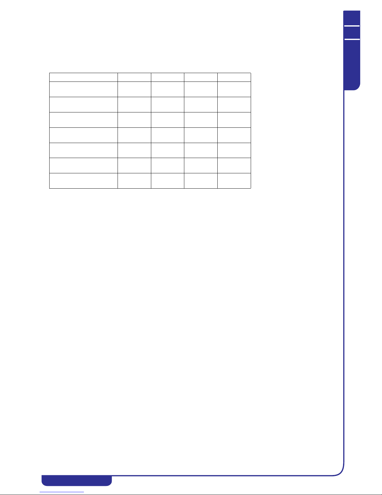
Model Width Depth Height
TAEevo Tech 015÷020
(mm)
(in)
560
22
1265
49.8
794
31.2
TAEevo Tech 031÷051
(mm)
(in)
660
26
1310
51.6
1400
55.1
TAEevo Tech 081÷161
(mm)
(in)
760
29.9
1865
73.4
1447
57
TAEevo Tech 201÷351
(mm)
(in)
865
34
2255
88.8
2065
81.3
TAEevo Tech 381÷401
(mm)
(in)
1150
45.2
2790
110
2091
82.3
TAEevo Tech 402÷602
(mm)
(in)
1255
49.4
3295
129.7
2140
84.2
TAEevo Tech 702÷802
(mm)
(in)
1251
49.2
3350
131.9
2153
84.7
OPERATING AND MAINTENANCE MANUAL
Chapter 5 - Installation
TAEevo Tech 015÷802 60 Hz UL
23
The data in this manual are not binding and they can be modified by the manufacturer without notice. Reproduction of this manual is strictly prohibited
EN
ENGLISH
CHAPTER 5
INSTALLATION
ATTENTION
Before installing or operating these units, ensure that all personnel involved have read and understood Chapter 2
“Safety”. The unit must be installed in accordance with current national legislation in the country of use.
5.1 Inspection
As soon as the unit has been unpacked check it carefully for damage.
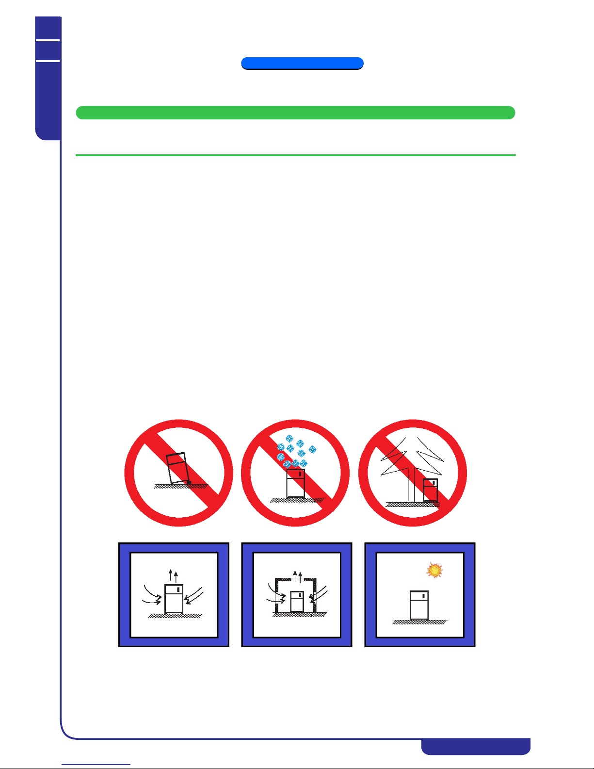
5.2 Location
1. The unit can be installed either outdoors or in an enclosed environment, depending on the degree of IP protection
of the electrical panel and the unit itself.
2. If the unit is installed indoors the place of installation must be well ventilated. In certain cases it may be necessary
to install ventilation fans or extractor fans in order to reduce room temperature.
3. The ambient air must be clean, avoid sea ambients (brackish air), and not contain flammable gas or corrosive
solvents.
4. The minimum and maximum working ambient temperature are specified on the unit data plate. Ensure that the
unit is not installed in flows of hot air emitted by other equipment.
In extremetemperature conditions, the protection devices may trip.
5. Do not obstruct or interfere with the air flow produced by the unit; comply strictly with the minimum spaces/
distances specified in the installation drawings.
6. The machine must be installed on a perfectly horizontal flat surface, built and calculated to withstand the
machine’s operating weight, especially in the contact points highlighted in the installation drawing. In the event
of installations which fail to comply with the above requirements, the manufacturer’s warranty cover will
immediately become null and void and the unit could malfunction or even lock out.
7. Leave free space around the unit for access during service interventions (see Attachments).
8. Do not install the plant in sites exposed to strong winds; if unavoidable, install suitable windscreens.
See point 1.
OPERATING AND MAINTENANCE MANUAL
Chapter 5 - Installation
TAEevo Tech 015÷802 60 Hz UL
24
The data in this manual are not binding and they can be modified by the manufacturer without notice. Reproduction of this manual is strictly prohibited
ENGLISH
EN
5.3 Freeze protection
Even if the minimum operating temperature is higher than 0°C/32°F, during shutdown periods in the cold season the unit may
be subject to temperatures that are lower than 0°C/32°F.
In such cases if the water is not drained out of the unit ethylene or propylene glycol antifreeze should be added to the water
in the following percentages:
In accordance with the chilled water outlet temperature, to avoid the formation of ice ethylene or propylene glycol antifreeze
should be added to the water in the following percentages:
NOTE
The water flow rate must correspond to the value stated in the technical specifications or in the selection software.
The conditions specified in the table do not guarantee anti-freeze protection with the machine operating in bypass mode
between water delivery and return, and with the machine water inlet and outlet fittings shut off.
ATTENTION
The anti-freeze setting is 4°C/39°F. To reduce the anti-freeze setting edit parameter AL26.
For water outlet temperatures lower than 6 °C you must add a suitable quantity of antifreeze solution.
5.3.1 Operating limits
The operating limits are decided at the time of sale. Refer to the data specified in the contract.
Ambient T up to
[°C] (°F)
Ethylene Glycol
[% by weight]
Propylene Glycol
[% by weight]
0 (32) 0 0
-5 (23) 15 18
-10 (14) 25 27
-15 (5) 30 33
-20 (-4) 40 40
Water outlet T up to
[°C] (°F)
Ethylene Glycol
[% by weight]
Propylene Glycol
[% by weight]
Standard machine
7 (45) 0 0
3 (37) 20 20
0 (32) 20 25
-3 (27) 25 30
-5 (23) 30 30
-7 (19) 35 35
-10 (14) 35 40
Special machine
-15 (5) 45 45
-20 (-4) 50 50
Ambient air temperature
Evaporator water
inlet temperature
Evaporator water
outlet temperature
Water temperature
gradient
Min Max Min Max Min Max Min Max
°C/°F °C/°F °C/°F °C/°F
-5/23
43/109
(1)
0/32 35/95 -5/23 30/86
4/7 10/18
5/23
43/109
(1)
-5/23 35/95 -10/14 30/86

OPERATING AND MAINTENANCE MANUAL
Chapter 5 - Installation
TAEevo Tech 015÷802 60 Hz UL
25
The data in this manual are not binding and they can be modified by the manufacturer without notice. Reproduction of this manual is strictly prohibited
EN
ENGLISH
NOTE
For water outlet temperatures <= +5°C /41°F we recommend the use of anti-freeze solutions (compatible with the contact
materials);
(1) reference value for the range with outlet water temperature of 15°C/59°F.
5.4 Hydraulic connections
NOTE
All the unit’s hydraulic connections must be made by the user.
1. Connect the unit to the water pipes observing the water flow direction as shown in the attached dimensional
drawings.
2. Provide two valves (one at the inlet, one at the outlet) to isolate the unit in the case of maintenance work without
having to empty the user water circuit.
3. Fill the tank with water using:
• a remote filling system, bleeding the air from the tank manually if necessary by means of the manual bleed
valve.
• if the water circuit is subject to frequent infiltrations of air it is good practice to install an automatic bleed
valve.
4. If the unit is supplied without pump make sure the pump installed by the user has its suction port connected
directly to the tank outlet connection in the event of a closed user circuit.
5. If the unit is supplied without pump make sure the pump installed by the user has its outlet port connected directly
to the unit inlet connection in the event of a user circuit that is open to the atmosphere.
NOTE
The pump must never run dry.
ATTENTION
If the unit is not equipped with the hydraulic uni t a pump must be inst alled for the evaporation water circuit.
For any maintenance requirements it is advisable to install a water drain cock at the lowest point of the circuit.
Evaporator water connections sizes:
NOTE
The machine interior is equipped with the fittings for BSP/NPT reducers, to be installed by the user.
Unit model TAEevo
Tech
015÷020 031÷051 081÷161 201÷351 381÷401
Evaporator IN/OUT
water connections
Rp 3/4” R p 1” Rp 1” 1/2 Rp 2” Rp 2” 1/2
Unit model TAEevo Tech 402÷602 702÷802 Unit with tank maximum pressure [bar/PSI]
Evaporator IN/OUT water
connections
Rp 2” 1/2 Rp 3” 6/87

OPERATING AND MAINTENANCE MANUAL
Chapter 5 - Installation
TAEevo Tech 015÷802 60 Hz UL
26
The data in this manual are not binding and they can be modified by the manufacturer without notice. Reproduction of this manual is strictly prohibited
ENGLISH
EN
Process water inlet Process water outlet
Pump type: Ebara 3D Pump type: Ebara 2CD
Pump type: Lowara NSC Pump type: Lowara CIE
When filling the circuit with liquid check to ensure the absence of air bubbles and contaminants. If the pump runs
noisily or emits anomalous noise it may be necessary to bleed the liquid circuit in order to prime the pump.
The procedure is as follows:
• unscrew the filler/breather plug at the top of the pump
• fill the hydraulic circuit until water starts to overflow from the filler hole
• refit the plug and tighten it
Repeat the operation if the pump continuous to run noisily, in such a way as to eliminate any air that had
previously remained trapped in the impeller vanes.
Load/vent plug
Drain plug
Load/vent plug
Drain plug
Load/vent plug
Drain plug
Load/vent plug
Drain plug

OPERATING AND MAINTENANCE MANUAL
Chapter 5 - Installation
TAEevo Tech 015÷802 60 Hz UL
27
The data in this manual are not binding and they can be modified by the manufacturer without notice. Reproduction of this manual is strictly prohibited
EN
ENGLISH
5.4.1 Evaporator water limit features
ATTENTION
For correct operation, install a fil ter (with mesh of 0,5/0,8 mm) close to the unit’s water inlet connection. Failure to
comply with this requirement may cause irreparable damage to the evaporator.
5.5 Expansion vessel
In the presence of a closed hydraulic circuit an expansion vessel must be installed.
The expansion vessel must always be installed on the pump suction side.
To calculate the minimum volume of the expansion vessel use the formula shown below, which is valid if the circuit pressure
is less than or equal to 0.5 bar / 7.2 PSI when the pump is idle and the maximum working pressure of the expansion vessel is
greater than or equal to 4 bar / 58 PSI.
The volume of expansion vessel V in litres is provided by the formula:
V = 2 · Vt · (Ptmin - Ptmax)
where:
Calculation example:
Vt=200 litres
percent ethylene glycol by volume=30%
tmin=5°C from table Ptmin=(1.045+1.041)/2 = 1.043
tmax=40°C from table Ptmax=1.0282
V=2 · 200 · (1.043 - 1.0282)=5.92 litres
Vt= Total circuit volume in litres
Ptmin= Specific density at minimum temperature that can be reached by the water throughout a twelve month
period expressed in °C (also during system shutdown)
Ptmax= specific density at minimum temperature that can be reached by the water throughout a twelve month
period expressed in °C (also during system shutdown)

OPERATING AND MAINTENANCE MANUAL
Chapter 5 - Installation
TAEevo Tech 015÷802 60 Hz UL
28
The data in this manual are not binding and they can be modified by the manufacturer without notice. Reproduction of this manual is strictly prohibited
ENGLISH
EN
Specific densities table P
5.6 Electrical connections
The machine must be connected to the main power supply in accordance with the laws and regulations in force in the country
of installation, after verifying the wiring diagram annexed to the unit.
Voltage, frequency and the number of phases must comply with the values indicated on the machine data plate.
Main distribution systems in United States:
Main distribution systems in Canada:
% Glycol 0% 10% 20% 30% 40%
Temperature [°C](°F)
-20(-4) 1.0036 1.0195 1.0353 1.0 511 1.0 669
-10(14) 1.0024 1.0177 1.033 1.0483 1.0635
0(32) 1.000 8 1.0155 1.0 303 1.045 1.0598
10(50) 0.9988 1.013 1.0272 1.0414 1.0556
20(68) 0.9964 1.0101 1.0237 1.0374 1.051
30(86) 0.9936 1.0067 1.0199 1.033 1.0461
40(104) 0.9905 1.003 1.0156 1.0282 1.0408
System Nominal Voltage Utilization Voltage
120 115 110
240/120 230/115 220/110
600
480
240
575
460
230
550
440
220
480 460 440
480/277
208/120
460/266
200/115
440/254
190/110
240/120 230/115 220/110
240/120 230/115 220/110
System Nominal Voltage Utilization Voltage
240
480
600
230
460
575
220
440
550
240/120 230/115 220/110

OPERATING AND MAINTENANCE MANUAL
Chapter 5 - Installation
TAEevo Tech 015÷802 60 Hz UL
29
The data in this manual are not binding and they can be modified by the manufacturer without notice. Reproduction of this manual is strictly prohibited
EN
ENGLISH
For mains power input:
1. Connect the machine (terminal in the electrical panel) to the earth system of the building;
2. Provide protection against direct contact of at least NEMA Type 1 upline from the power cable;
3. Fit a device protecting the power cable from overcurrent (short-circuit) (see indication in the electrical diagram)
upline from the power cable. For this purpose, all protection devices must be homologated (“listed”).
4. Use conductors which can carry the maximum current required at the maximum ambient operating temperature,
according to the type of installation chosen (seeindication in the electrical diagram). Use only UL marked copper
cables, in conformity with NEC (NATIONAL ELECTRICAL CODE) and CEC (CANADIAN ELECTRICAL
CODE).
5. After the connection to the circuit breaker/switch (as indicated in the wiring diagram), the unit’s power cable must
exit the unit by the appropriate hole positioned on the back panel and identified by a l abel with the indication of
the power supply.
5.7 Phase Monitor
By means of a Phase Monitor device (see unit electrical schematic) the electronic controller is able to monitor the unit’s
power supply, stopping the unit in the case of missing phases or an incorrect phase sequence.
Tripping of the Phase Monitor shuts down the unit and displays alarm ALc1.
A certain level of power supply instability is perfectly normal. If the frequency with which the unit is shut down due to
tripping of the Phase Monitor tends to increase unacceptably, contact your local electricity company to find a solution.
ATTENTION
Never tamper with the Phase Monit or under any circumstances.
600
480
240
575
460
230
550
440
220
600
480
240
575
460
230
550
440
220
600/347
480/277
416*/240
208/120
575/332
460/266
400*/230
200/115
550/318
440/254
380*/220
190/110
System Nominal Voltage Utilization Voltage

OPERATING AND MAINTENANCE MANUAL
Chapter 6 - Starting
TAEevo Tech 015÷802 60 Hz UL
30
The data in this manual are not binding and they can be modified by the manufacturer without notice. Reproduction of this manual is strictly prohibited
ENGLISH
EN
CHAPTER 6
STARTING
ATTENTION
Before starting this type o f unit, ensure that all personnel invo lved have read and understood Ch apter 2 “Safety”.
ATTENTION
When first starting after a stop of several days, ensure that the casing heating element of each compressor is switched
on for at least 12 hours before pressing the start button.
ATTENTION
On starting the unit:
1) If the high pressure alarm trips (b1HP/b2HP/b1hP/b2hP) without the compressor having started, stop the unit
immediately by setting it to off on the controller.
Now check the refrigerant circuit high pressure value.
2) If the Phase Monitor alarm ALc1 trips check the correct phase sequence upline from the unit. The ALc1 alarm may be
generated by tripping of the protections upline from the phase monitor.
1. Check that the unit shut-off valves are open.
2. Check that the tank has been completely filled with water and that the air has been bled out correctly.
3. Check that the ambient temperature is within the range indicated on the unit’s data plate.
4. Use the pressure gauge on the rear panel of the unit to check that the pressure is approximately 0.5 bar / 7.2 PSI
(only for closed hydraulic circuits).
5.Check that the main switch is in the OFF position (“O”).
6.Check that the unit power suppl y voltage is correct.
7.Power the unit by means of the line protection d evice.
8.Close the unit’s main switch by setting it to the ON position (“I”).
9.Check that water is flowing through the evaporator.
10.To start the unit perform the following procedure (For more information consult Chapter 7
“Electronic controller”)
From unit OFF (stand-by) press and release button to switch the unit on or off in chiller mode. With the unit
on LED is lit.
11. On three-ph ase power supply models make sure the compressor operates correctly (no anomalous noise and no
overheating) and check that the fans and the pump (if present) rotate in the correct direction.
If necessary, invert two phase wires of the power supply line.
12. Check that the pressure difference between the pressure gauge reading with the pump running and the reading
with the pump idle is higher than the available pressure head with the maximum pump flow rate. If the difference
is lower this means that the water flow rate is higher than the maximum permissible value. To avoid damaging the
pump increase the pressure drop in the hydraulic circuit, for example by partially closing a shut-off cock on the
pump outlet.

OPERATING AND MAINTENANCE MANUAL
Chapter 6 - Starting
TAEevo Tech 015÷802 60 Hz UL
31
The data in this manual are not binding and they can be modified by the manufacturer without notice. Reproduction of this manual is strictly prohibited
EN
ENGLISH
13. If at the time of first startup the ambient temperature is high and the water temperature in the hydraulic circuit is
significantly higher than the operating value (e.g. 25-30°C / 77-86°F) this means that the chiller is starting in
overloaded conditions resulting in possible tripping of the protections. To reduce the overload you can
progressively close (without closing it completely!) a valve at the chiller outlet to reduce the flow rate of water
passing through it. As the water temperature in the hydraulic circuit approaches the working value, the valve can
be re-opened.
14. The unit is now ready to start operating.
If the thermal load is lower than that produced by the unit, the water temperature decreases until it reaches the
setpoint value set following the instructions. Chapter 7 “Electronic controller”
Once the SETPOINT value has been reached the controller monitoring the water inlet temperature will stop the
compressor. In these conditions the water pump runs constantly.
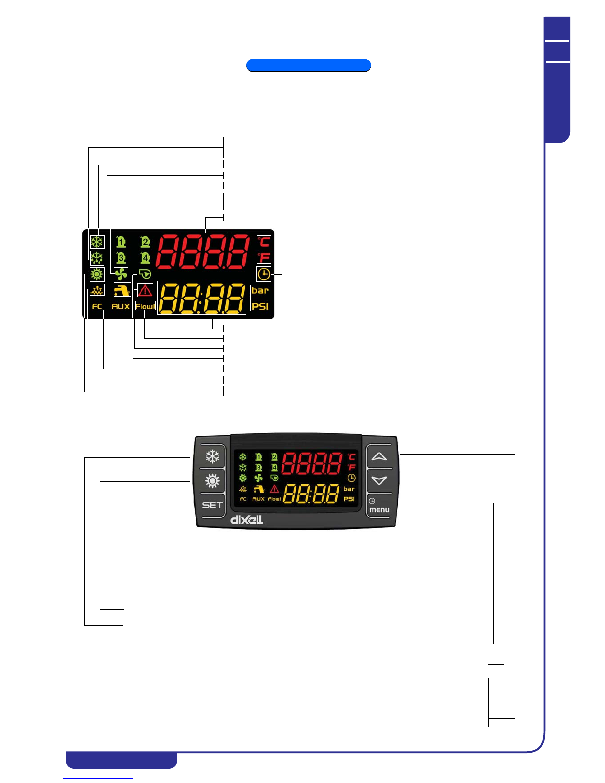
OPERATING AND MAINTENANCE MANUAL
Chapter 7 - Electronic controller
TAEevo Tech 015÷802 60 Hz UL
32
The data in this manual are not binding and they can be modified by the manufacturer without notice. Reproduction of this manual is strictly prohibited
ENGLISH
EN
CHAPTER 7
ELECTRONIC CONTROLLER
7.1 User interface
7.2 Function of buttons
The icon is flashing during the countdown of the interval between defrost cycles.
The icon is steady on during the defrost cycle (not used).
Compressors operating status icon, lit if the associated compressor is running.
Flashing if the compressor is in timer controlled starting mode.
Shows a temperature value when lit.
If lit in programming mode show temperature setpoints
or differentials.
Flashing if at least one alarm is present
Flashing if the pressure switch digital input is active with the pump running.
Lower display
Shows a pressure value when lit. If lit in programming mode shows
pressure setpoints or differentials.
Clock icon (pumps, compressors operating hours).
When lit in programming mode shows the work load hours.
Flashing in the functions menu indicates the time remaining before
defrost start.
Lit if at least one of the water pumps is running.
FC (not used). AUX lit with tank auxiliary heater on.
Lit if heaters (anti-freeze) heaters are on.
Heat pump operating mode icon (not used).
Lit if the domestic hot water production function is active (not used).
Lit if at least one condensing fan is running.
Upper display
Chiller operating mode icon.
Press twice from the main mask to display the real working setpoint (if present).
Press for 3 seconds from the main mask to edit the chiller setpoint.
Press once in the lower display probes menu to alternate the display of the circuits.
Press once from the main mask to display the chiller setpoint.
Press once in programming mode to edit or confirm a parameter value.
Press once in the ALrM menu to reset the alarm.
Press once to switch the unit ON or OFF in heat pump mode
(not used in chiller-only units).
Press once to switch the unit ON or OFF in chiller mode.
Press once to gain access to the functions menu.
Press once in programming mode to quit the parameters or parameter editing mode.
Press once to display temperature/pressure values on the upper/lower display.
Press once in programming mode to scroll the parameters or increase a parameter value.
Press for 1 second in programming mode to change the parameters access level. See “7.13.1 Access to
parameters”.
Press once from the main mask to display temperature/pressure values on the upper/lower display.
Press once in programming mode to scroll the parameters or decrease a parameter value.
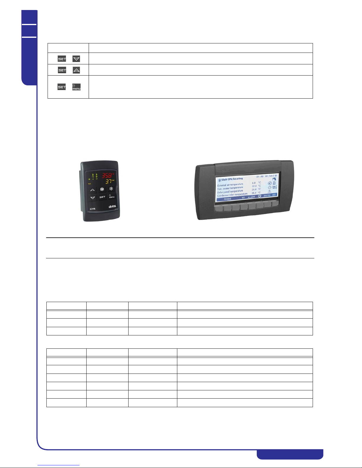
OPERATING AND MAINTENANCE MANUAL
Chapter 7 - Electronic controller
TAEevo Tech 015÷802 60 Hz UL
33
The data in this manual are not binding and they can be modified by the manufacturer without notice. Reproduction of this manual is strictly prohibited
EN
ENGLISH
7.2.1 Function of combined buttons
7.3 Remote terminal
There is a choice of two types of terminals for converting the unit to remote control (with LED display or LCD keypad).
The terminal generally shows the same parameters as the local display. The display can be customized with the dedicated
parameters (see “7.41 Parameters description-settings”)
In the absence of communication between the control unit and the remote terminal the upper display shows the message
“
” (no link).
NOTE
To convert the semi-graphic LCD display on the door of the electrical panel (mod. TAEevo Tech 381÷802) to remote control,
the relevant remote control kit must be ordered.
7.4 Probes key
This chapter refers to the probes; for the positioning of these probes consult the refrigerant circuit diagram and the electrical
diagram.
Descriptions of the probes utilised are given below:
Models TAEevo Tech 015÷401:
Models TAEevo Tech 402÷802:
BUTTONS FUNCTION
+
To enter programming mode (pressed for 3 seconds).
+
To exit programming phase.
+
In programming mode:
Press once from the main mask to display the “user” parameters;
Press twice from the main mask to display the “service” parameters.
Duplicate remote control with LED display. Semi-graphic remote control with LED display.
Probe code Board label Board terminals Description
BTWOT EOut PB1 Tank water outlet temperature probe (temperature control)
BEWOT Out1 PB2 Evaporator water outlet temperature probe (anti-freeze)
BAT1 Et PB6 Ambient temperature probe
Probe code Board label Board terminals Description
BTWOT EOut PB1 Tank water outlet temperature probe
BEWOT1 Out1 PB2 Evaporator 1 water outlet temperature probe
BHP1 CdP1 PB3 Circuit 1 high pressure transducer
BHP2 CdP2 PB4 Circuit 2 high pressure transducer
BEWOT2 Out2 PB5 Evaporator 2 water outlet temperature probe
BAT1 Et PB6 Ambient temperature probe
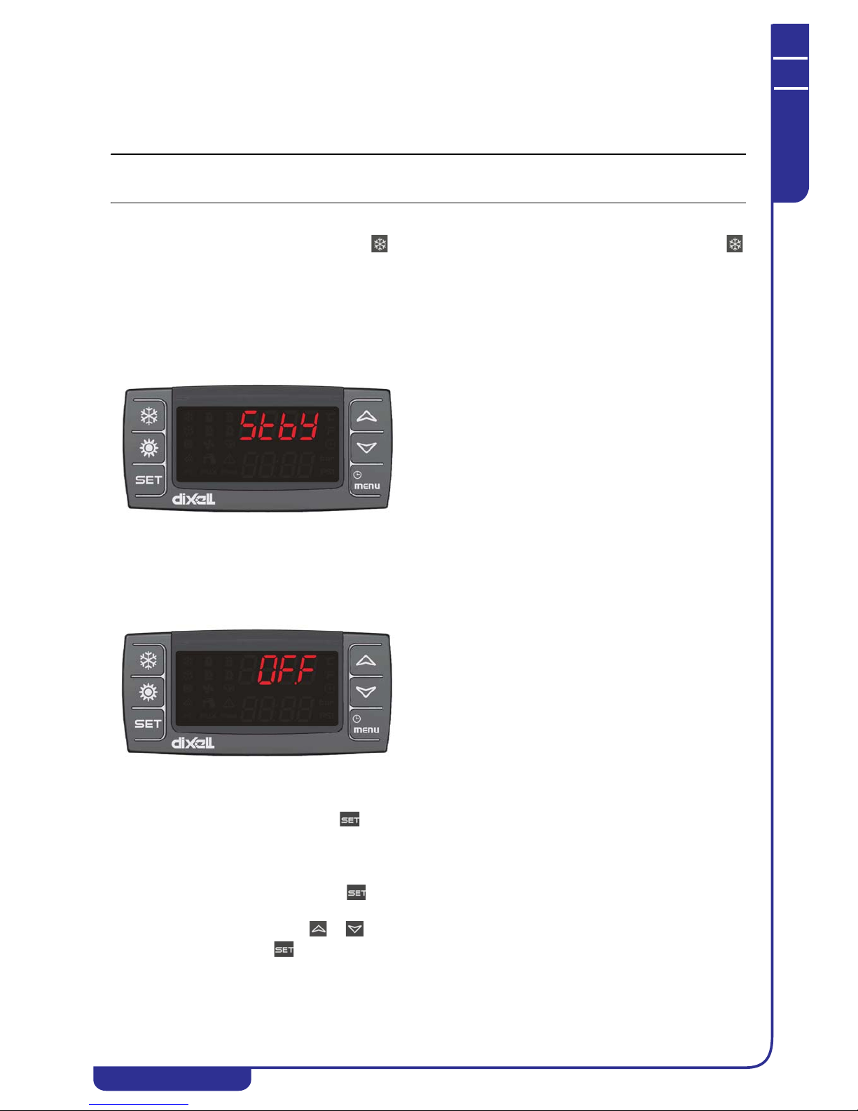
OPERATING AND MAINTENANCE MANUAL
Chapter 7 - Electronic controller
TAEevo Tech 015÷802 60 Hz UL
34
The data in this manual are not binding and they can be modified by the manufacturer without notice. Reproduction of this manual is strictly prohibited
ENGLISH
EN
7.5 Unit start/stop
The unit can be switched on and off as follows:
• From the keypad (local or remote)
• From a digital input configured as remote ON/OFF
• Makes it possible to gain access to parameters programming mode.
NOTE
In case of a power loss, when pow er is restored the unit will be ON if it was ON at the time of power loss, and OFF if it was
OFF.
7.5.1 Start from the keypad
From unit OFF (stand-by) press and release button to switch the unit on or off in chiller mode. With the unit on LED
is lit.
Stand-by mode is set each time the unit is switched off from chiller operating mode. Also in stand-by the controller makes it
possible to:
• Display the measured values
• Manage the alarm situation by displaying and signalling.
• Programmable
When the unit is in stand-by the controller shows the label
on the display.
7.5.2 Start from a digital input
The unit can be switched on/off from a digital input configured as remote On/OFF.
The power-off command (local or remote) always assumes priority with respect to the power-on command. If the unit is
powered-off with a local command it must be powered back on with a local command.
When the unit is in OFF status from a digital input the controller shows the label
. on the display.
7.6 Setpoint
7.6.1 Display the setpoint
To display the setpoint press and release the key.
With the unit in stand-by the lower display will show SetC (chiller set).
The upper display will show the set value.
7.6.2 Change the setpoint
To change the unit working setpoint press the key for at least 3 seconds and the working setpoint SetC (chiller set) will
appear in flashing mode.
The setpoint can be changed using the or buttons.
To save the new setpoint, press or wait for the time-out to exit programming mode.
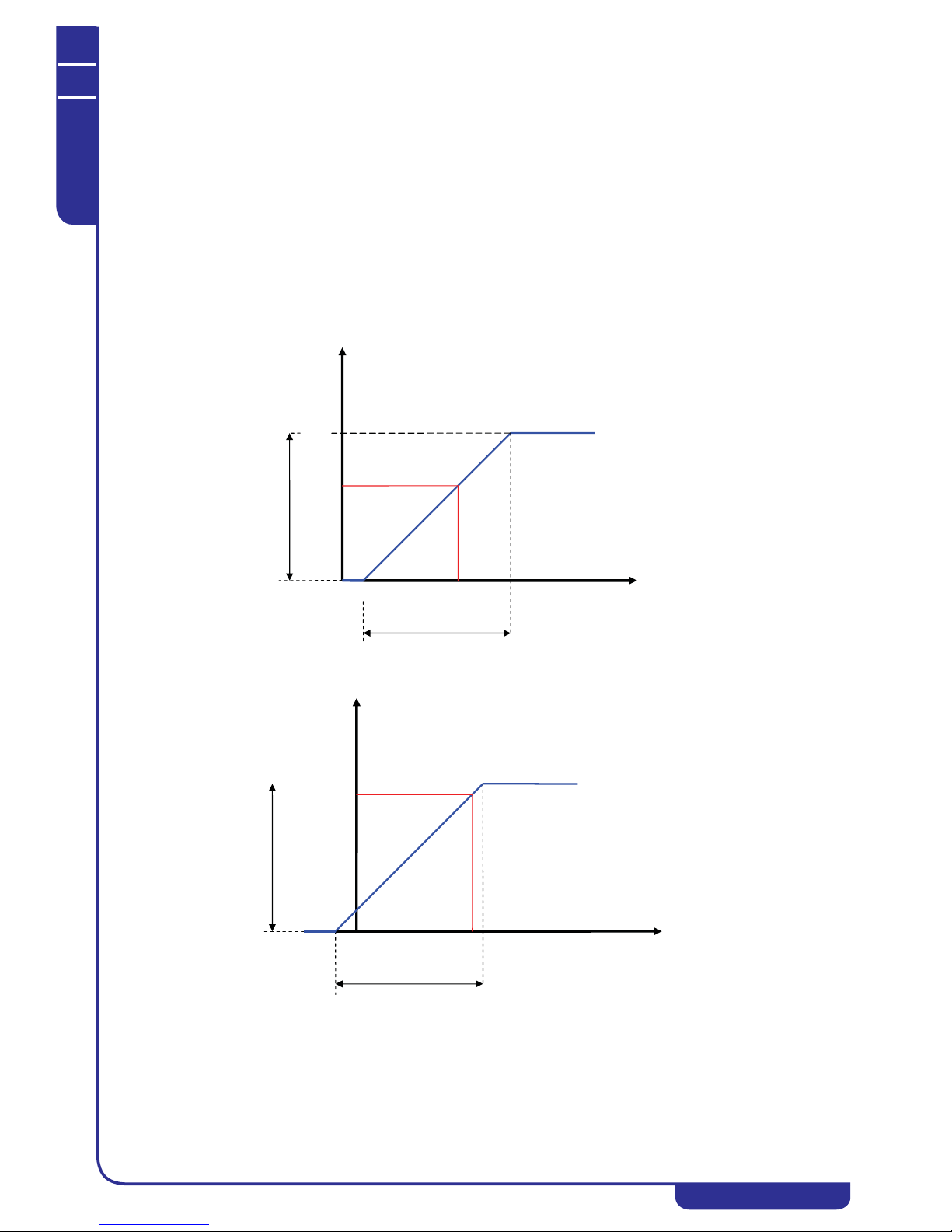
OPERATING AND MAINTENANCE MANUAL
Chapter 7 - Electronic controller
TAEevo Tech 015÷802 60 Hz UL
35
The data in this manual are not binding and they can be modified by the manufacturer without notice. Reproduction of this manual is strictly prohibited
EN
ENGLISH
7.7 Dynamic setpoint function
The regulator allows the operating setpoint to be modified by adding or subtracting a coefficient proportional to the external
air temperature.
For industrial applications, the purpose of this function is to prevent condensate from forming on the surface of the
component cooled by the unit.
The operating setpoint increases proportionally as the ambient temperature rises; the difference between the ambient
temperature and the operating setpoint is a value which can be set by means of parameter Sd03, with values from 23 ÷ 41°F.
To activate the function, set the following parameters:
Chiller setpoint ST01= 32°F
Max. increase in dynamic setpoint Sd01= 86°F
Temperature differential between external air and dynamic setpoint Sd05= 54°F
External air temperature - dynamic setpoint delta Sd03= 23 to 41°F
The graphs below illustrate operation of the dynamic setpoint (SEtr) with Sd03 set at 39°F and 25°F.
For example, with ambient T of 75°F the operating setpoint SEtr= 68°F in case 1 and SEtr= 82°Fcase 2.
Case 1 - Sd03= 39
Case 2 - Sd03= 25
3239507580100125
100
86
68
50
32
1
S
T1
Sd3
Ambient air T.
SEtr
Sd3
100
86
82
50
32
Ambient air T.
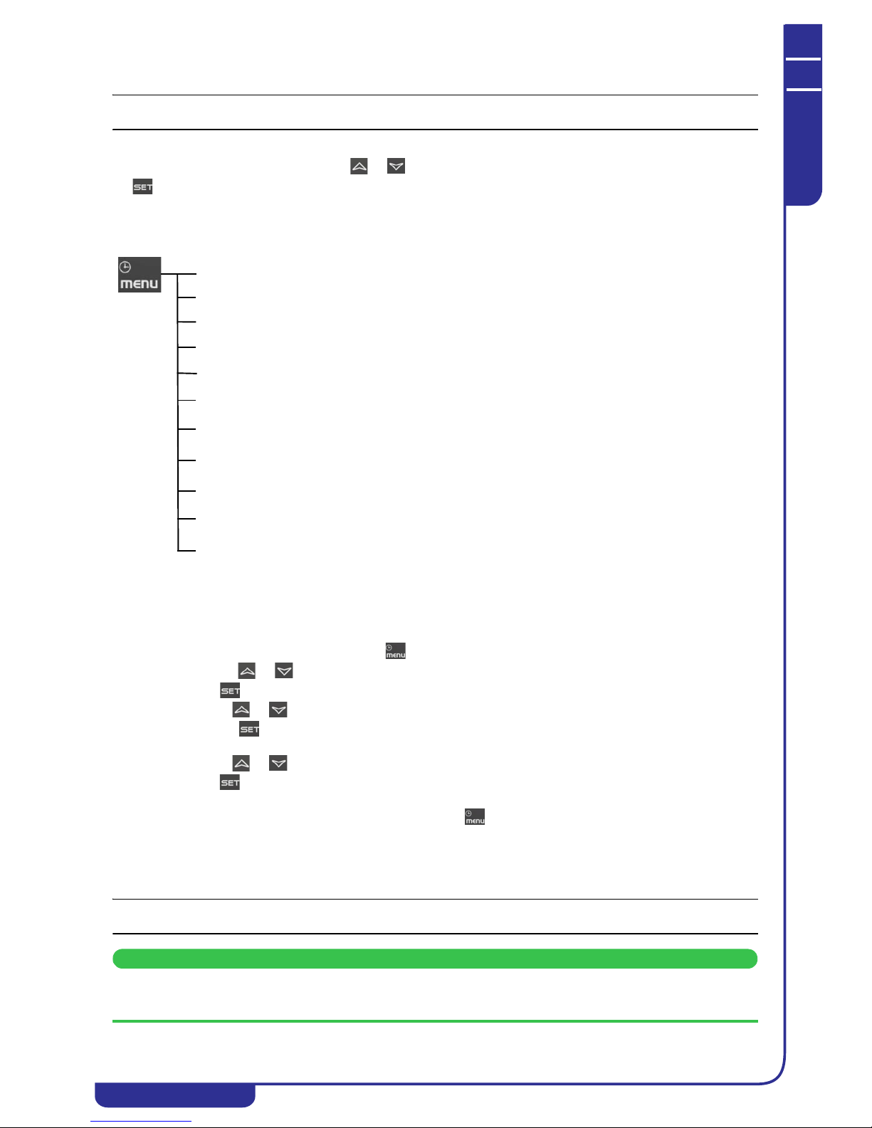
OPERATING AND MAINTENANCE MANUAL
Chapter 7 - Electronic controller
TAEevo Tech 015÷802 60 Hz UL
36
The data in this manual are not binding and they can be modified by the manufacturer without notice. Reproduction of this manual is strictly prohibited
ENGLISH
EN
7.8 How to display the internal values of a circuit
NOTE
This chapter is not applicable to single circuit units.
In normal operating mode circuit no. 1 is always displayed by default.
To switch from one circuit to another use the or buttons to select an identification label within a circuit and press
the button.
7.9 Functions menu button “Menu”
Access to Functions Menu enables the user to:
7.9.1 CrEn - Enable or disable the single circuit
With the CrEn submenu the operation of a single circuit can be disabled for maintenance purposes or to isolate it in the event
of malfunctions.
Proceed as follows:
• Open the functions menu by pressing
• With the or buttons select the function CrEn on the lower display;
• Press . The lower display shows Cr1E while the upper display shows En;
• Use the or buttons to display the label Cr1E or Cr2E;
• Press the button for 3 seconds in correspondence with label Cr1E or Cr2E . The upper display shows En
in flashing mode;
• Use the or buttons to select label diS (circuit operation disabled) or En (circuit operation enabled);
• Press to confirm the set function and proceed to the next circuit (only the loads associated with the circuit
are disabled);
To exit the CrEn function and return to normal display mode press or wait for the time-out.
In normal operation if one of the circuits is set to diS the lower display shows a flashing label alternated with the parameter
shown at that time.
If circuit 1 is in diS mode the label shown on the lower display is b1dS = circuit 1 disabled.
If circuit 2 is in diS mode the label shown on the lower display is b2dS = circuit 2 disabled.
NOTE
Label b2dS is present only on units with two refrigerant circuits.
ATTENTION
The CrEn function is enabled also on single circuit units. If you proceed to disable the only circuit present on these
units, the unit will suspend its entire cooling capacity.
ALrM function
Display and reset active alarms (see 7.11.1).
Display and clear the alarms log (see 7.12.12).
Upload instrument parameters to the smart key (see 7.14).
Enable / disable operation of a single circuit
ALOG function
UPL function
CrEn function
COEn function
COSn function
Cond function
dF function
Enable / disable operation of a single compressor
Display and reset the number of starts of each compressor
Display and reset the running hours of the controlled loads
Display the percentage of operation of the proportional outputs for control of the
condensing fans speed
Tank heater probe display
Display the time remaining before the start of the defrost cycle (heat pumps only).
uS function
Hour function
ENABLE or DISABLE the operation of a water pump using the key (if present)
POEn function
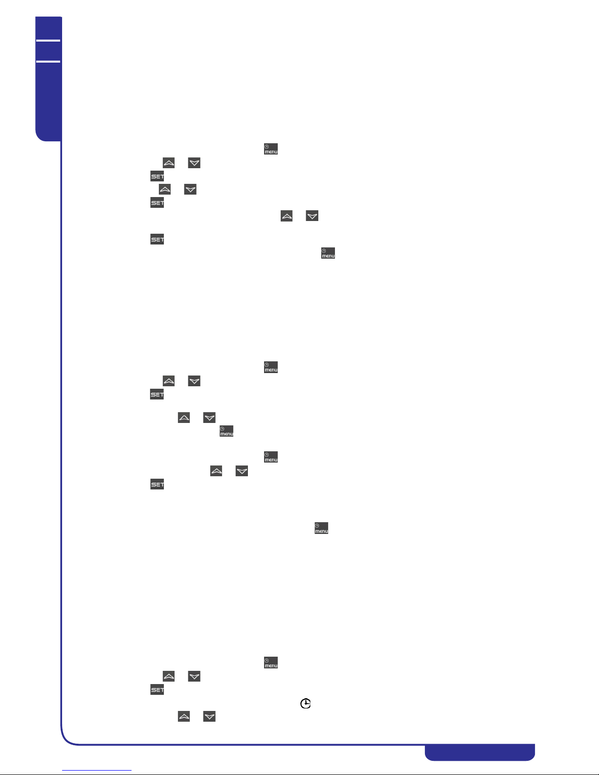
OPERATING AND MAINTENANCE MANUAL
Chapter 7 - Electronic controller
TAEevo Tech 015÷802 60 Hz UL
37
The data in this manual are not binding and they can be modified by the manufacturer without notice. Reproduction of this manual is strictly prohibited
EN
ENGLISH
7.9.2 COEn - Enable or disable the single compressor
With the COEn submenu the operation of a single compressor within a circuit can be disabled for compressor maintenance
purposes or to isolate it in the event of malfunctions.
The compressor status labels in the COEn function are:
• CO1E = operating status of compressor no. 1;
• CO2E = operating status of compressor no. 2;
• CO3E = operating status of compressor no. 3 (only two circuit units) ;
• CO4E = operating status of compressor no. 4 (only two circuit units) ;
To enable or disable the compressors proceed as follows:
• Open the functions menu by pressing
• With the or buttons select function CrEn
• Press ; the lower display shows CO1E whil e the upper display shows En
• Use the or buttons to select the required label on the lower display. The upper display shows En
• Press for 3 seconds in correspondence with the label identifying the compressor to be disabled
• The upper display shows flashing En; use or to select the diS(compressor operation disabled) or En
(compressor operation enabled) function
• Press to confirm the selected function and proceed to the next compressor
To exit the COEn function and return to normal display mode press or wait for the time-out.
7.9.3 COSn - Display and reset the number of compressor starts
The number of compressor starts can be viewed in the COSn submenu. The labels displayed are:
• C1S compressor 1 starts
• C2S compressor 2 starts
• C3S compressor 3 starts
• C4S compressor 4 starts
The number of starts is displayed in the lower display with a resolution of 10 starts. For example, if the number 2 is
displayed, the compressor starts are 20 in number.
To display the number of starts proceed as follows:
• Open the functions menu by pressing
• With the or buttons select the function COSn
• Press . The label of the single load C1S is shown on the upper display; the lower display shows the number
of starts multiplied by 10.
• With buttons or display all the configured compressors.
To return to normal display mode press or wait for the time-out.
To reset the number of compressor starts proceed as follows:
• Open the functions menu by pressing
• In function COSn use or to select the label C1S or C2S or C3S or C4S.
• Press for 3 seconds in correspondence with load C1S or C2S or C3S or C4S. The lower display now
shows the number of starts in flashing mode (reset in progress) and then the value “0” indicating that the
number has been reset.
• At this point the starts of the next compressor are displayed.
To exit the reset function and return to normal display mode press or wait for the time-out.
7.9.4 Hour - Display and reset the running hours of the loads
In the Hour submenu you can display the running hours of each compressor and also of the water pump. The labels displayed
are:
• CO1H compressor 1 running hours
• CO2H compressor 2 running hours
• CO3H compressor 3 running hours
• CO4H compressor 4 running hours
• EP1H evaporator water pump running hours
• EP2H evaporator second water pump running h ours
As for the number of starts, the running hours are shown on the upper display with a reso lution of 10 hours.
To view the running hours proceed as follows:
• Open the functions menu by pressing
• With the or buttons select the Hour function
• Press . The label of the single compressor is shown on th e lower display; the upper display shows the
number of running hours multiplied by 10. The icon will be illuminated.
• With buttons or display all the configured compressors.

OPERATING AND MAINTENANCE MANUAL
Chapter 7 - Electronic controller
TAEevo Tech 015÷802 60 Hz UL
38
The data in this manual are not binding and they can be modified by the manufacturer without notice. Reproduction of this manual is strictly prohibited
ENGLISH
EN
To return to normal display mode press or wait for the time-out.
To reset the running hours proceed as follows:
• Open the functions menu by pressing
•In the Hour function use or to select the label CO1H or CO2H or CO3H or CO4H or EP1H or
EP2H
• Press fo r 3 seconds in correspon dence with the compressor label CO 1H or CO2H or CO3H or CO4H or
EP1H or EP2H; the upper display will show the running hours in flashing mode (reset in progress) followed
by 0 to confirm that the value has been reset, and then progresses to the next load.
To exit the reset function and return to normal display mode press or wait for the time-out.
7.9.5 Cond - Display of percentage / number of condensing steps
In the functions menu you can view the working percentages of the fans proportional o utput.
Cnd1 Condensing fans control proportional output.
Proceed as follows to display:
• Open the functions menu by pressing
• With the or buttons select the Cond function
• Hold down button . The lower display shows Cnd1, the upper display shows the work percentage.
To return to normal display mode press or wait for the time-out.
In dual circuit units, to display the number of fan steps activated open the functions menu by pressing :
• With the or buttons select the Cond function
• Press . The lower display shows Cnd1, the upper display shows the number of steps activated.
Use or to select the label Cnd1 on the lower display; the upper display to shows the work percentage from 0 to 10 0
%:
To return to normal display mode press or wait for the time-out.
7.9.6 POEn - ENABLE or DISABLE the operation of a water pump using the key
Operation of a single pump can be disabled for servicing or to disconnect it from the circuit in the event of a malfunction.
In the functions menu it is displayed with the label POEn; inside the folder it is displayed as follows:
PE1E = evaporator no. 1 pump operating status.
The labels which identify the individual pumps are only displayed in the POEn function for the pumps actually present.
Access the function menu key:
• use the or keys to scroll the list and select the "POEn" function
• press the key: the bottom display shows "PE1E" and the top display "En";
• select the pump for disabling by pressing the or keys (labels "PE1E", "PE2E".. present depending on
the unit's configuration)
• press the key for 3 seconds: the top display shows a flashing "En". Pressing the or keys alternates
the contents of the top display between "En" and "diS"; pressing the key confirms the selected status
(En= enabled, diS=disabled).
Press the key to quit the POEn menu; it will also be shut down after a time-out.
Display status of the DISABLED water pump
During normal operation, if one of the pumps is disabled, a flashing label P1Ed, P2Ed, (evapo rator pumps 1 and 2) appears
on the bottom display, alternating with the parameter currently displayed.
7.10 uS - Tank heater probe display
The temperature / pressure value of the probes that control the auxiliary outputs can be displayed in the functions menu.
FUNCTION uS display of temperature / pressure value; identification label in function uS:
• uSt1 value measured by circuit 1 auxiliary probe
• uSt2 value measured by circuit 2 auxiliary probe
To display the probe values:
• With the or buttons select the uS function and press .
• The lower display will show the label uSt1 (if the auxiliary probe is configured for temperature) or uSP1
(if the auxiliary probe is configured for pressure); the upper display will show the measured temperature /
pressure value.
• Use or to display the measured pressure value of auxiliary output 2, if present.
• To return to normal display mode press or wait for the time-out.
OPERATING AND MAINTENANCE MANUAL
Chapter 7 - Electronic controller
TAEevo Tech 015÷802 60 Hz UL
39
The data in this manual are not binding and they can be modified by the manufacturer without notice. Reproduction of this manual is strictly prohibited
EN
ENGLISH
7.11 Alarms
The electronic controller manages the display, reset and logging of a large number of alarms.
7.11.1 Alarms display and reset (ALrM function)
ATTENTION
With this procedure you can reset all the alarms except for the compressor thermal cut-out alarms for which the
password will be required: 14.
To open the functions menu proceed as follows:
• Open the functions menu by pressing
• With the or buttons select the ALrM function
•Press .
If no alarms are present, pressing is not enabled.
• The lower display shows the label with the alarm; the upper display, if the alarm displayed is resettable, shows
the label rSt or no if the alarm condition is still present.
• Pressing in correspondence with label rSt resets the alarm and the system goes to the next one; if this too
is resettable, press to reset it and go to the next one.
• If you want to scroll through all the alarms present press or .
To exit the ALrM function and return to normal display mode press or wait for the time-out.
With the unit in StbY (stand-by) and the LED flashing, press and scroll with or to select the ALrM function
and press button to display the active alarm.
7.11.2 How to mute th e buzzer
The controller emits an audible signal to alert the operator to the presence of alarms (buzzer).
The buzzer is muted in the following ways:
• Automatic muting: the buzzer is muted when the situation that caused the alarm ceases.
• Manual muting: press and release one of the buttons; the buzzer will be muted even if the alarm condition
persists.
7.11.3 General alarms list
Alarm codes and indications are composed of letters and numbers that identify different alarm types.
The first letter of the alarm label identifies the type as follows:
•Letter A = unit alarm
•Letter b = circuit alarm
•Letter C = compressor alarm
The following tables contain a description of the alarms managed by the electronic circuit board. Some of the alarms
mentioned may not be referable to all unit models.
Outputs block
COD.
alarm
Alarm
Description
Alarm reset
Alarm Trip
Compressor
Pump
Fan
Heaters
AP1 Probe PB1 fault alarm A I X X X(1)
AP2 Probe PB2 fault alarm A I X X X(1)
AP3 Probe PB3 fault alarm A I X X X(1)
AP4 Probe PB4 fault alarm A I X X X(1)
AP5 Probe PB5 fault alarm A I X X X(1)
AP6 Probe PB6 fault alarm A I X X X(1)
APE1 Probe PB1 .. Probe Pb8 of I/O expansion A I X X X
APE2 Probe PB1.. Probe Pb8 of I/O expansion A I X X X
APE3 Probe PB1 .. Probe Pb8 of I/O expansion A I X X X
APE4 Probe PB1 .. Probe Pb8 of I/O expansion A I X X X
APE5 Probe PB1 .. Probe Pb8 of I/O expansion A I X X X
APE6 Probe PB1 .. Probe Pb8 of I/O expansion A I X X X
APE7 Probe PB1 .. Probe Pb8 of I/O expansion A I X X X
APE8 Probe PB1.. Probe Pb8 of I/O expansion A I X X X
AEFL Level sensor and/or flow meter alarm A/M R X X(2) X X

OPERATING AND MAINTENANCE MANUAL
Chapter 7 - Electronic controller
TAEevo Tech 015÷802 60 Hz UL
40
The data in this manual are not binding and they can be modified by the manufacturer without notice. Reproduction of this manual is strictly prohibited
ENGLISH
EN
1= If probe configured for anti-freeze - water heater control and Ar10 = 0.
2= With manual reset alarm.
3= Compressors stopped with only 1 water pump configured or with 2 water pumps configured and both in thermal alarm
state.
4= water heater elements off with only 1 water pump configured or with 2 water pumps configured and both in thermal alarm
status (in this case the water heater elements are switched on only by the evaporator anti-freeze protection setpoint).
(n)= identifies circuit 1 or circuit 2
Key:
A= automatic
M= manual
R= delayed
I= instantaneous
AtE1 Evaporator water pump thermal cutout M I X(3) X X X(4)
AtE2 Evaporator second water pump thermal cutout M I X(3) X X X(4)
AEE EEprom alarm M I X X X
ALSF Phase sequence alarm (NOT USED) A I X X X X
ASLA LAN communication with I/O expansion alarm A I X X X
ALc1 Phase monitor alarm A/M I X X X
AEUn Evaporator inlet high temperature unloading indication A R
ACF1 Configuration alarm A I X X X
ACF2 Configuration alarm A I X X X
ACF3 Configuration alarm A I X X X
ACF4 Configuration alarm A I X X X
ACF5 Configuration alarm A I X X X
ACF6 Configuration alarm A I X X X
ACF7 Configuration alarm A I X X X
ACF8 Configuration alarm A I X X X
ACF9 Configuration alarm A I X X X
AC10 Configuration alarm A I X X X
AC11 Configuration alarm A I X X X
AC12 Configuration alarm A I X X X
AC13 Configuration alarm A I X X X
AC14 Configuration alarm M I X X X
b(n)HP Circuit (n) high pressure switch (TAEevo Tech 015÷40 1 models only) A/M R X X
b(n)HP Circuit (n) high pressure switch and/or compressor thermal alarm
(TAEevo Tech 402÷802 models only)
A/M R X X
b(n)LP Circuit (n) low pressure switch A/M R X X
b(n)AC Anti-freeze in chiller circuit (n) A/M R X X
b(n)Ac Signalling of anti-freeze in chiller circuit (n) A/M R
b(n)hP High condensing pressure transducer circuit (n) M I X
b(n)lP Low cond ensing pressur e - (evaporatio n with low pressure transducer)
transducer circuit (n)
A/M R X
AEht Evaporator water inlet high temperature alarm M I X X
b1tF Circuit 1 fans thermal alarm M I X
b(n)Cu Signalling unloading temp. press. condensing circuit (n) A I
b(n)rC Circuit (n) recovery disabl ed signalling A I
C(n)tr Compressor (n) thermal alarm with AL47 = 0 – 1 M I X
Outputs block
COD.
alarm
Alarm
Description
Alarm reset
Alarm Trip
Compressor
Pump
Fan
Heaters

OPERATING AND MAINTENANCE MANUAL
Chapter 7 - Electronic controller
TAEevo Tech 015÷802 60 Hz UL
41
The data in this manual are not binding and they can be modified by the manufacturer without notice. Reproduction of this manual is strictly prohibited
EN
ENGLISH
7.11.4 Indications table
7.11.5 Probe faulty
7.11.6 High pressure sw itch alarm
(TAEevo Tech 015÷401 models only)
CODE
Alarm
Description
Alarm
Comp.
Heaters
Anti-freeze
water heater
Elements
support
Pump
Evap.
Deliv. Fan
Cond. pump
Cond.
fan
Cir1 Cir2
Auxiliary
relay
AEUn Evaporator unloading indication
b(n)Cu Unloading indication from condensing press. temp. circuit (n)
b(n)Eu Unloading indication from evaporator low temp. circuit (n)
C(n)Mn Compressor (n) maintenance
AEP1 Evaporator water pump maintenance
AEP2 Second evaporator pump maintenance
noL Indication of communication loss between keypad or
controller 2 remote terminals configured with same address
Atr(n) Remote terminal alarm
Display labels meaning AP1 probe PB1÷AP6 alarm probe PB6 alarm
Cause of trip Probe configured and converted value off range
Reset Probe not configured or converted value within range
Reset Automatic
Icon Flashing
Action Alarm relay + buzzer activated
Regulators
In accordance with the particular probe in error status, the regulators associated
with the probe in question will be disabled. An error of the temperature control
probe will cause a unit shut-down, while an error of the external air temperature
probe will result in disabling of the functions associated with the probe in
question (e.g. dynamic setpoint)
Display labels meaning b1HP (circuit 1 high pressure digital input)
b2HP (circuit 2 high pressure digital input)
Cause of trip With unit in ON status and circuit high pressure switch input active
Reset Input inactive
Reset Reset is always manual
Icon Flashing
Action Alarm relay + buzzer activated
Regulators
Alarm Relay + buzzer activated
Inversion valve follows its control
Recovery valve follows its contr ol
Free cooling ON/OFF valve follows its contr ol
Auxiliary relay Follow(s) its/their control
No-load start-up valve Follows its control
Delivery fan Follows its control
Fans If Par. FA02= 0 fans operating mode depends on the compressor, with alarm
active the fans are forced at the maximum speed for 60 seconds before
switching off
If Par. FA02= 1 fans operating mode independent from the compressor, with
alarm active the fans are forced at the maximum speed for 60 seconds then are
subjected to speed control
Compressors of unaffected circuits Follows its control
Pump down solenoid of non-condensing
circuits affected
Follows its control
Pump down solenoid of affected circuits off

OPERATING AND MAINTENANCE MANUAL
Chapter 7 - Electronic controller
TAEevo Tech 015÷802 60 Hz UL
42
The data in this manual are not binding and they can be modified by the manufacturer without notice. Reproduction of this manual is strictly prohibited
ENGLISH
EN
7.11.7 High pressure switch alarm and/or compressor thermal alarm
(TAEevo Tech 402÷802 models only)
7.11.8 Low pressure switc h alarm
Display labels meaning b1HP (circuit 1 high pressure digital input) and/or compressor thermal alarm
b2HP (circuit 2 high pressure digital input) and/or compressor thermal alarm
Cause of trip With unit in ON status and circuit high pressure switch input active and/or
compressor thermal alarm
Reset Input inactive
Reset Reset is always manual
Icon Flashing
Action Alarm relay + buzzer activated
Regulators
Alarm Relay + buzzer activated
Inversion valve follows its control
Recovery valve follows its control
Free cooling ON/OFF valve follows its control
Auxiliary relay Follow(s) its/their control
No-load start-up valve Follows its control
Delivery fan Follows its control
Fans If Par. FA02= 0 fans operating mode depends on the compressor, with alarm
active the fans are forced at the maximum speed for 60 seconds before
switching off
If Par. FA02= 1 fans operating mode independent from the compressor, with
alarm active the fans are forced at the maximum speed for 60 seconds then are
subjected to speed control
Compressors of unaffected circuits Follows its control
Pump down solenoid of non-condensing
circuits affected
Follows its control
Pump down solenoid of affected circuits off
Display labels meaning b1LP (circuit 1 low pressure digital input)
b2LP (circuit 2 low pressure digital input)
Cause of trip With low pressure switch input of active circuit
The alarm is not signalled:
1. On compressor starting for time AL01
2. If time AL64 from activation of the digital input has not elapsed
Reset Input deactivation
Reset Automatic - becomes manual after AL05 trips / hour (reset procedure in
functions menu)
Icon Flashing
Action Alarm relay + buzzer activated
Regulators
Alarm Relay + buzzer activated
Inversion valve follows its control
Recovery valve follows its control
Free cooling ON/OFF valve follows its control
Auxiliary relay Follow(s) its/their control
No-load start-up valve Follows its control
Delivery fan Follows its control
Condensing fans Off
Support /water heater /anti-freeze Follows its control
Evaporator/ condenser water pump(s) Follows its control
Compressors off
Pump down solenoid off

OPERATING AND MAINTENANCE MANUAL
Chapter 7 - Electronic controller
TAEevo Tech 015÷802 60 Hz UL
43
The data in this manual are not binding and they can be modified by the manufacturer without notice. Reproduction of this manual is strictly prohibited
EN
ENGLISH
7.11.9 High pressure
7.11.10 L ow pressure
Display labels meaning b1hP (circuit 1 high pressur e analogue input)
b2hP (circuit 2 high pressure analogue input)
Cause of trip Condensing control probe detects value > set AL09
Reset Condensing control probe detects value < set AL09 - differential AL10
Res et Reset is always manual
Icon Flashing
Action Alarm relay + buzzer activated
Regulators
Alarm Relay + buzzer activated
Inversion valve follows its control
Recovery valve follows its contr ol
Free cooling ON/OFF valve follows its contr ol
Auxiliary relay Follow(s) its/their control
No-load start-up valve Follows its control
Delivery fan Follows its control
Condensing fans If Par. FA02= 0 fans operating mod e depends on the compressor, with alarm
active the fans are forced at the maximum speed for 60 seconds before
switching off
Support /water heater /anti-freeze Follows its control
Evaporator/ condenser water pump(s) Follows its control
Compressors of affected circuits Off
Compressors of unaffected circuits Follows its control
Pump down solenoid of unaffected circuits Follows its control
Pump down solenoid of affected circuits off
Display labels meaning b1lP (circuit 1 low pressure analogue input)
b2lP (circuit 2 low pressure analogue input)
Cause of trip The alarm is generated when the evaporation pressure alarm reads a pressure
value < set AL03
When the compressor is started the alarm is not generated for time AL01.
Reset If the evaporation control probe measures pressure > set AL03 + differential
AL04
Reset Automatic - becomes manual after AL05 trips / hour (reset procedure in
functions menu)
Icon Flashing
Action Relay + buzzer activated
Regulators
Alarm Relay + buzzer activated
Inversion valve follows its control
Recovery valve follows its contr ol
Free cooling ON/OFF valve follows its contr ol
Auxiliary relay Follow(s) its/their control
No-load start-up valve Follows its control
Delivery fan Follows its control
Condensing fans Off
Support /water heater /anti-freeze Follows its control
Evaporator/ condenser water pump(s) Follows its control
Compressors of affected circuits Off
Compressors of unaffected circuits Follows its control
Pump down solenoid of unaffected circuits Follows its control
Pump down solenoid of affected circuits off

OPERATING AND MAINTENANCE MANUAL
Chapter 7 - Electronic controller
TAEevo Tech 015÷802 60 Hz UL
44
The data in this manual are not binding and they can be modified by the manufacturer without notice. Reproduction of this manual is strictly prohibited
ENGLISH
EN
7.11.11 Anti-freeze alarm
The anti-freeze alarm is reset automatically. It switches to manual reset after 3 trips/hour.
With the unit in Stand-by or OFF the anti-freeze alarm message is tripped in reference to the chiller and heat pump setpoints.
7.11.12 Chiller mode anti-freeze alarm
7.11.13 Level sen sor and/or flow meter alarm
Each time the water pump is started the level sensor alarm is disregarded for time AL15 to allow the hydraulic circuit to
reach steady state conditions. In normal operating conditions, if the level sensor is in alarm for time AL17 the compressor is
stopped and label AEFL is displayed: the water pump continues to run for additional time AL16 after which, if the level
sensor is still in alarm, the pump is stopped.
At this point the alarm persists with manual reset so it must be reset manually.
Parameter AL18 is the time for which the level sensor must not be in alarm in order to allow a reset.
AL15 Pump start level sensor alarm delay
Used to set a delay for acknowledgement of the level sensor alarm from starting of the water pump to allow the flow rate to
reach steady state conditions.
AL16 Alarm persistence time to stop the water pump.
Defines the level sensor alarm persistence time (digital input active) after which the alarm switches from automatic reset to
manual reset and the water pump is stopped.
AL17 Level sensor input active duration
Used to set a time during which the level sensor alarm must persist before the alarm is signalled. The count starts after time
AL15 and makes it possible to filter out possible flow rate drops or the presence of air pockets in the water circuit.
AL18 Level sensor input not active duration
Used to set a time during which the level sensor alarm must remain inactive; after this interval, if the alarm is automatic reset
type it is reset, while it can be reset manually if it is manual reset type.
Chiller Operation
Display labels meaning b1AC (chiller mode circuit 1 anti-freeze alarm )
b1Ac (chiller mode circuit 1 anti-freeze alarm indication)
With the alarm active and a dual circuit unit both the labels are displayed
(b1AC-b2AC/b1Ac-b2Ac).
Cause of trip In operation and in stand-by remote OFF, if the anti-freeze control probe detects
a temperature < set AL26 for at least AL28 seconds.
Reset Anti-freeze control probe detects a temperature > set A26 + differential AL27.
Reset Automatic - becomes manual after AL29 trips / hour (reset procedure in
functions menu).
Icon Flashing
Action The compressors are stopped and the alarm label is displayed (b1AC b2AC)
and the Alarm relay + buzzer are activated
Regulators
Alarm If AL30=1 Relay + buzzer activated + anti-freeze heaters
Inversion valve Follows its control
Recovery valve Follows its control
Free cooling ON/OFF valve Follows its control
Auxiliary relay Follow(s) its/their control
No-load start-up valve Follows its control
Delivery fan If air-air unit off
Condensing fans Follows its control
Support /water heater /anti-freeze If air-air unit off, otherwise follows its control
Support /water heater /anti-freeze With alarm from ID activated
Evaporator/ condenser water pump(s) Follows its control
Compressors Off
Pump down solenoid Off

OPERATING AND MAINTENANCE MANUAL
Chapter 7 - Electronic controller
TAEevo Tech 015÷802 60 Hz UL
45
The data in this manual are not binding and they can be modified by the manufacturer without notice. Reproduction of this manual is strictly prohibited
EN
ENGLISH
ATTENTION
Activation of alarm relay + buzzer occurs only if the level sensor alarm is active during a normal operating stage.
Otherwise exclusively an illuminated signal is generated (flashing icon).
NOTE
The alarm is always automatic reset with the unit in stand-by or remote OFF (pump stopped).
Level sensor alarm manual reset:
If the alarm features manual reset, to reset it the operator must open the functions menu (reset procedure in functions menu).
Display labels meaning AEFL (level sensor and/or flow meter alarm)
Cause of trip The alarm is not acknowledged for time AL15 after starting of the water pump.
Alarm signalled if ID active for time AL17.
Reset ID not active for time AL18
Reset Automatic - becomes manual if ID active for time AL16 counted at expiry of
AL17 (reset procedure in functions menu)
Icon Flashing Flow!
Action Alarm relay + buzzer activated only if the level sensor alarm is active during a
normal operating stage.
Regulators
Alarm Relay + buzzer activated only if the level sensor alarm is active during a normal
operating stage.
Inversion valve Follows its control
Recovery valve Follows its control
Free cooling ON/OFF valve Follows its control
Anti-freeze / Support / water heater Off
Auxiliary relay Follows its control
Delivery fan Off
Condensing fans Follows its control
Support /water heater /anti-freeze Follows its control
Evaporator water pump With CO15 = 1 always on; off when alarm switches to manual reset (only in
chiller or heat pump mode)
Evaporator water pump With CO15 = 2 follows its control; off when alarm switches to manual reset
(only in chiller or heat pump mode)
Condenser water pump Follows its control
Compressors Off
Pump down solenoid Off

OPERATING AND MAINTENANCE MANUAL
Chapter 7 - Electronic controller
TAEevo Tech 015÷802 60 Hz UL
46
The data in this manual are not binding and they can be modified by the manufacturer without notice. Reproduction of this manual is strictly prohibited
ENGLISH
EN
7.11.14 Compress ors thermal alarm
7.11.15 Fan the rmal alarm
Display labels meaning C1tr (compressor 1 thermal alarm) -…C4tr (compressor 4 thermal alarm)
Cause of trip With digital input active.
The alarm is not acknowledged for AL19 after compressor start.
Reset If ID inactive
Reset Manual from menu ALrM with password request
Icon Flashing
Action Alarm relay + buzzer activated
Regulators
Alarm Relay + buzzer activated
Inversion valve follows its control
Recovery valve follows its control
Free cooling ON/OFF valve follows its control
Auxiliary relay Follows its control
No-load start-up valve Follows its control
Delivery fan Follows its control
Condensing fans Follows its control
Support /water heater /anti-freeze Follows its control
Evaporator/ condenser water pump(s) Follows its control
Compressor affected If Par. AL47 = 0 or 1 Off
Compressor unaffected If Par. AL47 = 0 follows its control - If Par. AL47 = 1 Off
Pump down solenoid Switched off if only 1 compressor per circuit, otherwise follows its control
Display labels meaning b1tF (circuit 1 condensing fan thermal alarm)
Cause of trip With configured circuit digital input active
Reset With digital input inactive.
Reset Manual. (reset procedure in functions menu)
Icon Flashing
Action Alarm relay + buzzer activated
Regulators
Alarm Relay + buzzer activated
Inversion valve follows its control
Recovery valve follows its control
Free cooling ON/OFF valve follows its control
Auxiliary relay follows its control
No-load start-up valve follows its control
Delivery fan Off
Condensing fans Off
Support /water heater /anti-freeze Follows its control
Evaporator/ condenser water pump(s) Follows its control
Compressors Off
Pump down solenoid Off

OPERATING AND MAINTENANCE MANUAL
Chapter 7 - Electronic controller
TAEevo Tech 015÷802 60 Hz UL
47
The data in this manual are not binding and they can be modified by the manufacturer without notice. Reproduction of this manual is strictly prohibited
EN
ENGLISH
7.11.16 High condensing pressure unloading indication in chiller mode
7.11.17 Hig h condensing pressure recovery disabling indication
Display labels meaning b1Cu (unloading indicatio n from circuit 1 condenser coil)
b2Cu (unloading indication from circuit 2 condenser coil)
Cause of trip In operation if the probe configured as condensing pressure or temperature
control detects a value > CO44
Reset • if condensing pressure or temperature measures value < CO44 -
differential CO45
• with unloading active, after time setting Par. CO48
Reset Automatic
Icon Flashing
Action Alarm relay + buzzer NOT activated
Regulators
Alarm Relay + buzzer NOT activated
Inversion valve Follows its control
Recovery valve follows its control
Free cooling ON/OFF valve follows its control
Auxiliary relay follows its control
No-load start-up valve follows its control
Delivery fan Follows its control
Condensing fans Follows its control
Support /water heater /anti-freeze Follows its control
Evaporator/ condenser water pump(s) Follows its control
Compressors Follows its control
Pump down solenoid Follows its control
Display labels meaning b1rC (circuit 1 recovery disabling signal)
b2rC (circuit 2 recovery disabling signal)
Cause of trip In o p e r a t i o n i f t he probe configure d as condensing pressure control detects a
value > set rC06
Reset • If condensing pressure or temperature measures value < set rc06
- differential rC07
• From recovery disabling function activated after time set in
Par. rC08
Reset Automatic
Icon Flashing
Action Alarm relay + buzzer NOT activated
Regulators
Alarm Relay + buzzer NOT activated
Inversion valve Follows its control
Recovery valve Off
Free cooling ON/OFF valve Follows its control
Auxiliary relay Follows its control
No-load start-up valve Follows its control
Delivery fan Follows its control
Condensing fans Follows its control
Support /water heater /anti-freeze Follows its control
Evaporator/ condenser water pump(s) Follows its control
Compressors Follows its control
Pump down solenoid Follows its control
OPERATING AND MAINTENANCE MANUAL
Chapter 7 - Electronic controller
TAEevo Tech 015÷802 60 Hz UL
48
The data in this manual are not binding and they can be modified by the manufacturer without notice. Reproduction of this manual is strictly prohibited
ENGLISH
EN
7.11.18 Evaporator inlet high water temperature unloading indication
7.11.19 Evapo rator water pump group thermal alarm
Display labels meaning AEun (unloading from evaporator indication)
Cause of trip operation if evaporator water inlet temperature measured is > set CO40 for time
set in Par.CO42
Reset • If the measured water temperature is < set CO40 - differential
CO41
• From unloading function active after time set in Par. CO43
Reset Automatic
Action Alarm relay + buzzer NOT activated
Regulators
Alarm Relay + buzzer NOT activated
Inversion valve Follows its control
Recovery valve follows its control
Free cooling ON/OFF valve Follows its control
Auxiliary relay Follows its control
No-load start-up valve Follows its control
Delivery fan Follows its control
Condensing fans Follows its control
Support /water heater /anti-freeze Follows its control
Evaporator/ condenser water pump(s) Follows its control
Compressors Follows its control
Pump down solenoid Follows its control
Display labels meaning AtE1 (evaporator water pump thermal cutout)
AtE2 (evaporator second pump thermal cutout)
Cause of trip ID configured as evaporator water pump thermal cutout active
ID configured as evaporator second pump thermal cutout active
Reset With ID inactive
Reset Manual. (reset procedure in functions menu)
Icon Flashing
Action Alarm relay + buzzer activated
Regulators
Alarm Relay + buzzer activated
Inversion valve Follows its control
Recovery valve follows its control
Free cooling ON/OFF valve Follows its control
Auxiliary relay Follows its control
No-load start-up valve Follows its control
Delivery fan Off if no pump available
Condensing fans Off if no pump available
Support /water heater /anti-freeze Follows its control
Condenser / evaporator water pump Off if no pump available
Condenser water pump Follows its control
Compressors Off if no pump available
Pump down solenoid Off if no pump available

OPERATING AND MAINTENANCE MANUAL
Chapter 7 - Electronic controller
TAEevo Tech 015÷802 60 Hz UL
49
The data in this manual are not binding and they can be modified by the manufacturer without notice. Reproduction of this manual is strictly prohibited
EN
ENGLISH
7.11.20 Phase mo nitor alarm
7.11.21 Co mpressors maintenance alarm
7.11.22 Pump s maintenance alarm
7.11.23 EEprom alarm
NOTE
For unit configuration alarms “ACF1÷ACF9” and “AC10÷AC14”, contact technical assistance.
Display labels meaning ALc1
Cause of trip Phase monitor alarm
Reset Phase monitor not active alarm
Reset automatic - becomes manual after AL42 trips / hour (reset procedure in
functions menu). Recorded in alarms log exclusively with manual reset.
Icon Flashing
Action Alarm relay + buzzer activated
Regulators
Alarm Relay + buzzer activated
Other loads Off
Display labels meaning C1Mn (compressor 1 mai ntenance request)
C2Mn (compressor 2 maintenance request)
C3Mn (compressor 3 maintenance request)
C4Mn (compressor 4 maintenance request)
Cause of trip Compressor running hours > programmed hour meter setting
Reset Running hours reset (in functions menu, “Hour” function, hold down “set”
button for several seconds)
Reset Manual
Icon Flashing
Action Alarm relay + buzzer activated
Regulators
Alarm Relay + buzzer activated
Other loads Follow their control
Display labels meaning AEP1 (evaporator water pu mp maintenance request)
AEP2 (evaporator second pump maintenance request)
Cause of trip Pump running hours > programmed hour meter setting
Reset Running hours reset (in functions menu, “Hour” function, hold down “set”
button for several seconds)
Reset Manual
Icon Flashing
Action Alarm relay + buzzer activated
Regulators
Alarm Relay + buzzer activated
Other loads Follow their control
Display labels meaning AEE
Cause of trip Failed write to Eeprom
Reset -----Reset Manual
Icon Flashing
Action Alarm relay + buzzer activated
Regulators
Other loads Off

OPERATING AND MAINTENANCE MANUAL
Chapter 7 - Electronic controller
TAEevo Tech 015÷802 60 Hz UL
50
The data in this manual are not binding and they can be modified by the manufacturer without notice. Reproduction of this manual is strictly prohibited
ENGLISH
EN
7.11.24 Unit co nfiguration alarm
Display labels meaning
ACF1 Unit configured as heat pump and circuit inversion valve not configured
incorrect combination in values of defrost parameter (dF22/23)
ACF2 Unit configured for ON/OFF or proportional condensing control without configuration of the competent probe
(1 probe per circuit if separate condensing, at least 1 probe if single condensing).
In case of proportional control at least one of the following rules is not observed:
• FA09 + FA11 + FA12 < FA10
• FA12 < FA13
• FA07 < FA15 < FA08
In case of proportional control at least one of the following rules is not observed:
• FA18 + FA21 + FA20 < FA19
• FA21 < FA22
• FA16 < FA23 < FA17
In case of ON-OFF control the following rule is not observed:
• FA09 < FA10
In case of ON-OFF control with pump enabled the following rule is not observed:
• FA18 < FA19
In case of pump enabled and defrost enabled no condensing / evaporation probe per circuit.
In case of fans control with PWM signal continuous supply has been selected (CF83=0).
In case of step control enabled if step1 is not < step2 < step3 < step 4 in chiller mode / if step 4 is not < step3
< step2 < step 1 in heat pump mode.
ACF3 Two digital / analogue or relays configured with same function or configured without adeq uate resources
(e.g. compressor 3 thermal cutout configured but compressor 3 not configured).
ACF4 • CF59 = 1 and digital input not configured or CF59 = 2 and no NTC probe configured as
ambient air temperature.
• Unit configured as heat pump only and compressors plant enabled.
• CF03
0 and no condensing unit operation enabling digital input and loads configured.
• CF03
0 and all condensing unit operation enabling digital inputs and cooling / heating
demand configured.
• CF03 0 and capacity demands configured in mode that is incongruent with the configuration
of the compressors / capacity steps relay outputs.
ACF5 If circuit 2 is not configured and the resources have not been configured (pump-down relay, heating elements,
cycle inversion valve, condensing fans, recovery, auxiliary).
ACF6 Total number of compressors in the 2 circuits (CF04 + CF05) is:
•> 4
• > 4 and starting is not direct (CO10
0) or number of capacity steps (CF06) is 0
• > 2 and intermittent valve is enabled with ON times (CO08) and OFF times (CO09)
0
If pump-down operation is configured but in at least one circuit:
• The circuit pump-down solenoid relay is not configured.
• The pump-down is not performed by time and the pump-down pressure switch and circuit
evaporation probe are not configured and pump-down is enabled also in start-up or even the low
pressure switch is not configured
The compressor has been configured by means of parameters CF04 and CF05 but the relative relays have not
been installed:
•Compressor relay
• Valve intermittent when enabled from capacity control ON / OFF times (CO08 / CO09
0)
• or gas by-pass when the function is enabled (by-pass time
0)
• Starting part-winding
• Of capacity control for all capacity steps provided
A relay has been configured:
• Associated with a compressor not enabled by parameters CF04 and CF05
• Valve intermittent when ON or OFF times =0
• Capacity control not envisaged
OPERATING AND MAINTENANCE MANUAL
Chapter 7 - Electronic controller
TAEevo Tech 015÷802 60 Hz UL
51
The data in this manual are not binding and they can be modified by the manufacturer without notice. Reproduction of this manual is strictly prohibited
EN
ENGLISH
ACF7 evaporator pump
• defined (CO16
0) but no relays configured
• not defined (CO16 = 0) but one relay configured
condenser pump
• defined (CO21
0) but no relays configured
• not defined (CO21 = 0) but one relay configured
Evaporator / condenser pump configuration alarm due to anti-freeze
•if Ar24=1 and Ar25=0
or
•if Ar25=1 and there are no probes configured as NTC
or
•if Ar29=1 and there are no probes configured as NTC
ACF8 Temperature control probes configuration:
• one temperature control probe (in chiller ST09, in heat pump when ST10 is enabled) is not
correctly configured (does not exist or is not NTC)
• controller enabled with pressure control the associated pressure control probe is not defined
ACF9 Recovery enabled but in one circuit only certain resources are defined (the following are necessary:
condensing probe, recovery request digital input, recovery relay) or no output is def ined.
AC10 Compressors with inverter:
• there are at last 2 analogue outputs configured for capacity modulation of the same compressor
• the output is defined but the main relay of the compressor is not defined
• modulating compressor enabled and unit configured as condensing unit
AC11 Capacity controlled compressors
• digital scroll compressors
• at least 1 of the compressors defined has significance 0
• temperature control is not in neutral zone
AC12 (free cooling configuration) if:
• the free cooling output relay is not defined
• the probes for free cooling control are not defined
•if FS21 < FS22
•if FS01=2 and CF97=2
AC13 (domestic hot water configuration) if:
FS01>0 and:
• the out1 output relay is not defined
• domestic hot water temperature probe 1 is not configured
AC14 (relay outputs configuration) if:
a relay is configured with values 75 or 76
Cause of trip Incorrect programming
Reset Correct programming
Reset Automatic
Icon Flashing
Action Alarm relay + buzzer activated
Regulators
Alarm Relay + buzzer activated
Other loads Off

OPERATING AND MAINTENANCE MANUAL
Chapter 7 - Electronic controller
TAEevo Tech 015÷802 60 Hz UL
52
The data in this manual are not binding and they can be modified by the manufacturer without notice. Reproduction of this manual is strictly prohibited
ENGLISH
EN
7.12 iCHILL input/output configurations
7.12.1 Configuration of analog ue inputs PB1 - PB2 – PB5 – PB6
0. Disabled
1. PTC temperature probe on delivery outlet of compressor n° 1
2. PTC temperature probe on delivery outlet of compressor n° 2
3. PTC temperature probe on delivery outlet of compressor n° 3
4. PTC temperature probe on delivery outlet of compressor n° 4
5. Not used
6. Not used
7. PTC temperature probe for solar panel temperature
8. NTC temperature probe on evaporator inlet
9. NTC temperature probe on evaporator outlet 1
10. NTC temperature probe on evaporator outlet 2
11. NTC temperature probe on evaporator common output/support heater management (air/air unit)
12. NTC temperature probe on common input for condenser hot water
13. NTC temperature probe on condenser hot water input of circuit 1
14. NTC temperature probe on condenser hot water input of circuit 2
15. NTC temperature probe on condenser hot water output of circuit 1
16. NTC temperature probe on condenser hot water output of circuit 2
17. NTC temperature probe on common output for condenser hot water
18. NTC temperature probe for free cooling mode
19. NTC temperature probe for external air temperature dynamic set point / boiler function / changeover
20. NTC temperature probe for combined defrost on circuit 1
21. NTC temperature probe for combined defrost on circuit 2
22. NTC temperature probe for auxiliary output on circuit 1
23. NTC temperature probe for auxiliary output on circuit 2
24. NTC temperature probe for domestic hot water temperature 1
25. NTC temperature probe for domestic hot water temperature 2
26. NTC temperature probe for solar panel temperature
27. NTC temperature probe for condensation on circuit 1
28. NTC temperature probe for condensation on circuit 2
If the input is to be used as a digital input, the configuration will be from o1 to C75 and will take on the meaning seen in
“Configuration of digital inputs ID1 – ID18”
7.12.2 Configuration of analog ue inputs PB3 - PB4
0. Disabled
1. PTC temperature probe on delivery outlet of compressor n° 1
2. PTC temperature probe on delivery outlet of compressor n° 2
3. PTC temperature probe on delivery outlet of compressor n° 3
4. PTC temperature probe on delivery outlet of compressor n° 4
5. Not used
6. Not used
7. PTC temperature probe for solar panel temperature
8. NTC temperature probe on evaporator inlet
9. NTC temperature probe on evaporator outlet 1
10. NTC temperature probe on evaporator outlet 2
11. NTC temperature probe on evaporator common output/support heater management (air/air unit)
12. NTC temperature probe on common input for condenser hot water
13. NTC temperature probe on condenser hot water input of circuit 1
14. NTC temperature probe on condenser hot water input of circuit 2
15. NTC temperature probe on condenser hot water output of circuit 1
16. NTC temperature probe on condenser hot water output of circuit 2
17. NTC temperature probe on common output for condenser hot water
18. NTC temperature probe for free cooling mode
19. NTC temperature probe for external air temperature dynamic set point / boiler function / changeover
20. NTC temperature probe for combined defrost on circuit 1
21. NTC temperature probe for combined defrost on circuit 2
22. NTC temperature probe for auxiliary output on circuit 1
23. NTC temperature probe for auxiliary output on circuit 2
24. NTC temperature probe for domestic hot water temperature 1
25. NTC temperature probe for domestic hot water temperature 2
26. NTC temperature probe for solar panel temperature
27. Condensation probe on circuit n° 1 (NTC temperature / pressure 4÷20 mA / ratiometric 0÷ 5Volt)
28. Condensation probe on circuit n° 2 (NTC temperature / pressure 4÷20 mA / ratiometric 0÷ 5Volt)
29. Evaporation pressure probe in circuit 1
30. Evaporation pressure probe in circuit 2
31. Auxiliary output pressure probe 1

OPERATING AND MAINTENANCE MANUAL
Chapter 7 - Electronic controller
TAEevo Tech 015÷802 60 Hz UL
53
The data in this manual are not binding and they can be modified by the manufacturer without notice. Reproduction of this manual is strictly prohibited
EN
ENGLISH
32. Auxiliary output pressure probe 2
33. Pressure probe for 4..20 mA dynamic set point
34. Oil pressure probe on compressor 1 or circuit 1
35. Oil pressure probe on compressor 2 or circuit 2
If the input is to be used as a digital input, the configuration will be from o1 to C75 and will take on the meaning seen in
“Configuration of digital inputs ID1 – ID18”
7.12.3 Configuration of digital inputs ID1 – ID11
0. Disabled
1. Remote ON / OFF
2. Remote Chiller / heat pump
3. Flow switch / delivery fan thermal cutout
4. Hot side flow switch
5. Antifreeze alarm on circuit 1
6. Antifreeze alarm on circuit 2
7. High pressure switch on circuit 1
8. High pressure switch on circuit 2
9. Low pressure switch on circuit 1
10. Low pressure switch on circuit 2
11. High pressure on compressor 1
12. High pressure on compressor 2
13. High pressure on compressor 3
14. High pressure on compressor 4
15. Not used
16. Not used
17. Thermal cutout on compressor 1
18. Thermal cutout on compressor 2
19. Thermal cutout on compressor 3
20. Thermal cutout on compressor 4
21. Not used
22. Not used
23. Condensation fan thermal cutout on circuit 1
24. Condensation fan thermal cutout on circuit 2
25. Common condensation fan thermal cutout
26. Evaporator water pump 1 thermal cutout
27. Evaporator support water pump thermal cutout
28. Condenser water pump 1 thermal cutout
29. Condenser support water pump thermal cutout
30. Recovery request on circuit 1
31. Recovery request on circuit 2
32. Defrost start/end on circuit 1
33. Defrost start/end on circuit 2
34. Energy Saving
35. Oil pressure switch / float switch on compressor 1
36. Oil pressure switch / float switch on compressor 2
37. Oil pressure switch / float switch on compressor 3
38. Oil pressure switch / float switch on compressor 4
39. Not used
40. Not used
41. Pump down pressure switch on circuit 1
42. Pump down pressure switch on circuit 2
43. Digital input for general unit block alarm 1
44. Digital input for general alarm signal / unit block alarm 2
45. Digital input for automatic RTC enable (time band) / manual mode (keypad)
46. Digital input for operation with delivery fan only
47. Digital input for temperature control request
48. Digital input for chiller request
49. Digital input for heat pump request
50. Digital input for power step 2 request
51. Digital input for power step 3 request
52. Digital input for power step 4 request
53. Digital input for power step 5 request
54. Digital input for power step 6 request
55. Digital input for power step 7 request
56. Digital input for power step 8 request
57. Digital input for power step 9 request
58. Digital input for power step 10 request

OPERATING AND MAINTENANCE MANUAL
Chapter 7 - Electronic controller
TAEevo Tech 015÷802 60 Hz UL
54
The data in this manual are not binding and they can be modified by the manufacturer without notice. Reproduction of this manual is strictly prohibited
ENGLISH
EN
59. Digital input for power step 11 request
60. Digital input for power step 12 request
61. Digital input for power step 13 request
62. Digital input for power step 14 request
63. Digital input for power step 15 request
64. Digital input for power step 16 request
65. Domestic hot water pump flow switch
66. Solar panel water pump flow switch
67. Enable only domestic hot water production
68. Domestic hot water heater thermal cutout
69. Domestic hot water pump thermal cutout
70. Enable second domestic water set point
71. Phase sequence alarm
72. Domestic water operation priority
73. FC pump flow switch
74. Expansion valve alarm on circuit 1
75. Expansion valve alarm on circuit 2
7.12.4 Configuration of digital ou tputs RL1- RL8
0. Disabled
1. Alarm
2. Evaporator water pump / delivery fan
3. Evaporator support water pump
4. Anti-freeze resistance / support / boiler circuit 1
5. Anti-freeze resistance / support / boiler circuit 2
6. Recovery condenser water pump
7. Recovery condenser support water pump
8. Chiller / heat pump inversion valve on circuit 1
9. Chiller / heat pump inversion valve on circuit 2
10. 1st ON/OFF condensation ventilation step on circuit 1
11. 2nd ON/OFF condensation ventilation step on circuit 1
12. 3rd ON/OFF condensation ventilation step on circuit 1
13. 4th ON/OFF condensation ventilation step on circuit 1
14. 1st ON/OFF condensation ventilation step on circuit 2
15. 2nd ON/OFF condensation ventilation step on circuit 2
16. 3rd ON/OFF condensation ventilation step on circuit 2
17. 4th ON/OFF condensation ventilation step on circuit 2
18. Pump-down solenoid on circuit 1
19. Pump-down solenoid on circuit 2
20. Recovery valve on circuit 1
21. Recovery valve on circuit 2
22. Free cooling ON/OFF valve
23. Auxiliary output 1
24. Auxiliary output 2
25. Screw compressor intermittent valve on compressor 1
26. Screw compressor intermittent valve on compressor 2
27. Liquid injection solenoid valve on compressor 1
28. Liquid injection solenoid valve on compressor 2
29. Valve 1 for domestic hot water production
30. Valve 2 for domestic hot water production
31. Resistances (1st step) for domestic hot water production
32. Resistances (2nd step) for domestic hot water production
33. Resistances (3rd step) for domestic hot water production
34. Solar panel pump
35. ON/OFF valve to enable/disable solar panel coil
36. Domestic hot water pump
37. Hybrid exchanger 1 on circuit 1
38. Hybrid exchanger 2 on circuit 1
39. Hybrid exchanger 1 on circuit 2
40. Hybrid exchanger 2 on circuit 2
41. Summer/Winter operating mode on circuit 1
42. Summer/Winter operating mode on circuit 2
43. Defrost status on circuit 1
44. Defrost status on circuit 2
45. Circuit 1 in regulation status
46. Circuit 2 in regulation status
47. Domestic water production status

OPERATING AND MAINTENANCE MANUAL
Chapter 7 - Electronic controller
TAEevo Tech 015÷802 60 Hz UL
55
The data in this manual are not binding and they can be modified by the manufacturer without notice. Reproduction of this manual is strictly prohibited
EN
ENGLISH
48. Remote standby/off machine status
49. Water side solenoid valve on circuit 1
50. Water side solenoid valve on circuit 2
51. Direct start-up: compressor 1 relay
PW start-up: winding 1 relay on compressor 1
52. PW start-up: winding 2 relay on compressor 1
53. Step capacity control 1 on compressor 1
54. Step capacity control 2 on compressor 1
55. Step capacity control 3 on compressor 1
56. Gas bypass valve on start-up of compressor 1
57. Direct start-up: compressor 2 relay
PW start-up: winding 1 relay on compressor 2
58. PW start-up: winding 2 relay on compressor 2
59. Step capacity control 1 on compressor 2
60. Step capacity control 2 on compressor 2
61. Step capacity control 3 on compressor 2
62. Gas bypass valve on start-up of compressor 2
63. Direct start-up: compressor 3 relay
PW start-up: winding 1 relay on compressor 3
64. PW start-up: winding 2 relay on compressor 3
65. Step capacity control 1 on compressor 3
66. Step capacity control 2 on compressor 3
67. Step capacity control 3 on compressor 3
68. Gas bypass valve on start-up of compressor 3
69. Direct start-up: compressor 4 relay
PW start-up: winding 1 relay on compressor 4
70. PW start-up: winding 2 relay on compressor 4
71. Step capacity control 1 on compressor 4
72. Step capacity control 2 on compressor 4
73. Step capacity control 3 on compressor 4
74. Gas bypass valve on start-up of compressor 4
75. Laser function valve
7.12.5 Configuration of proportional outputs OUT1 and OUT2 (0 – 10 VOLT)
0. Output disabled
1. 0-10V output for evaporator pump in modulating mode
2. 0-10V free cooling modulating output
3. Laser function output
4. 0-10V auxiliary output 1
5. 0-10V auxiliary output 2
6. 0-10V output inverter compressor on circuit 1
7. 0-10V output inverter compressor on circuit 2
8. 0-10V output condensation fans on circuit 1
9. 0-10V output condensation fans on circuit 2
ON/OFF output, relay pilot, to enable configuration of a proportional output with the same characteristics as a digital output.
The displayed values range from o1 to c50, as per the digital outputs.
7.12.6 Configuration of proportional outputs OUT3 and OUT4 (0 – 10 VOLT/PWM)
0. 10 Output disabled
1. 0-10V output for evaporator pump in modulating mode
2. 0-10V free cooling modulating output
3. Laser function output
4. 0-10V auxiliary output 1
5. 0-10V auxiliary output 2
6. 0-10V output inverter compressor on circuit 1
7. 0-10V output inverter compressor on circuit 2
8. 0-10V output condensation fans on circuit 1
9. 0-10V output condensation fans on circuit 2
10. PWM output condensation fans on circuit 1
11. PWM output condensation fans on circuit 2
ON / OFF output, relay pilot, to enable configuration of a proportional output with the same characteristics as a digital
output. The displayed values range from o1 to c50, as per the digital outputs.
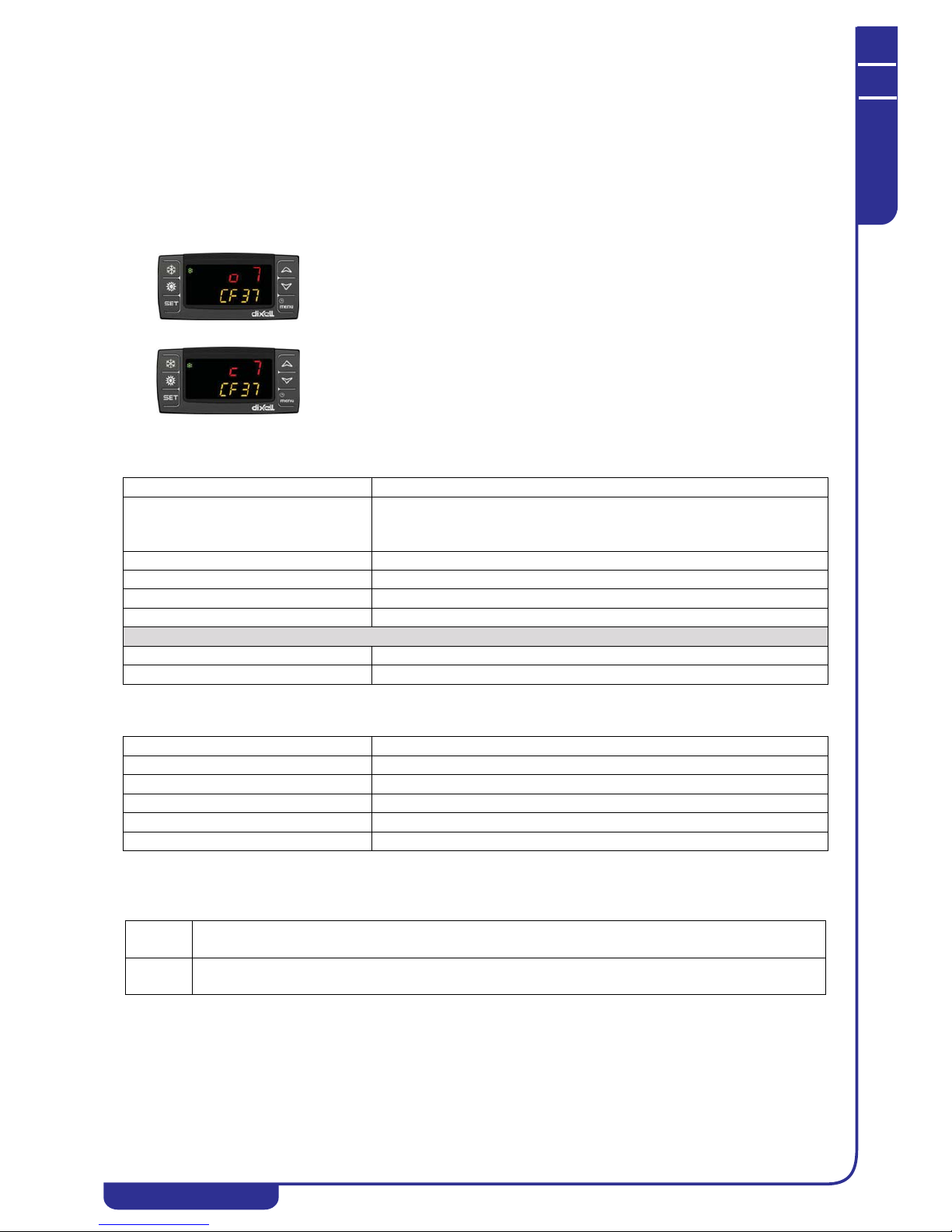
OPERATING AND MAINTENANCE MANUAL
Chapter 7 - Electronic controller
TAEevo Tech 015÷802 60 Hz UL
56
The data in this manual are not binding and they can be modified by the manufacturer without notice. Reproduction of this manual is strictly prohibited
ENGLISH
EN
7.12.7 Display in programming mode of polarity of digital inputs / ou tputs
The parameters enable the configuration of:
1. Digital inputs
2. Digital outputs (relays)
3. Proportional outputs configured as ON/OFF outputs
4. Analogue inputs configured as digital inputs
to enable assignment of a function and control of polarity.
Example of display in programming mode:
The lower display shows the parameter label (CF37) for configuration of the digital input ID8. The upper display shows label
“c” or “o” and the relative configuration number.
7.12.8 Remote terminal alarm
7.12.9 Remote terminal alarm
7.12.10 Alarm re lay / open - collector / buzzer notes
The unit features a general alarm relay that combines all alarms on a single output contact.
The relay is active with the following logic:
In the example, digital input ID8 is configured as a high pressure switch
on circuit 1, label “o”, active with contact OPEN.
In the example, digital input ID8 is configured as a high pressure switch
on circuit 1, label “c”, active with contact CLOSED.
Display labels meaning noL (no l ink signalling)
Cause of trip Incorrect connection between remote terminal and controller or two remote
terminals configured as present and both with same HW address (see position of
keypads address assignment switch)
Reset Correct connection - two different HW addresses
Reset Automatic
Icon Flashing
Action Alarm relay + buzzer activated
Regulators
Alarm Relay + buzzer activated
Other loads Follow their control
Display labels meaning Atr1 / Atr2
Cause of trip Remote terminal configured from parameter but not electrically connected
Reset Correct connection - remote terminal declared absent from parameter
Reset Automatic
Icon Flashing
Action Alarm relay + buzzer activated
ON With alarms not terminated;
With alarms not reset;
OFF With no alarms;
Unit power disconnected

OPERATING AND MAINTENANCE MANUAL
Chapter 7 - Electronic controller
TAEevo Tech 015÷802 60 Hz UL
57
The data in this manual are not binding and they can be modified by the manufacturer without notice. Reproduction of this manual is strictly prohibited
EN
ENGLISH
7.12.11 Dia gnostic of alarms that switch from automatic to manual
No. of trips per hour
Every hour is divided into 16 intervals each lasting 3600 / 16 = 225 seconds (3 minutes 45 seconds).
When the instrument is powered on each observation interval is flagged as “inactive”.
Each observation interval is initially flagged as “inactive” and subsequently, up to its termination (i.e. for 225 seconds) it is
flagged as “active” if at least one alarm trips. When each observation terminates the next one starts, remembering that the
observation is continuous and once the first 16 intervals have elapsed the 17th interval replaces the first, the 18th replaces the
second, and so forth.
In this manner the last hour of operation is always monitored and the “active” intervals can be counted. When the number of
active intervals exceeds the set limit, the alarm switches to manual.
Setting the limit to 0 the alarm will therefore be manual already at the first trip, while if the limit is set at 16 the alarm will
remain constantly automatic because the observation intervals are not 17 in number.
7.12.12 Display and delete the alarms log in the memory (ALOG function)
The function to display the alarm codes is active only if alarms are actually present.
• Enter the functions menu by pressing .
• Select the ALOG function.
•Press .
If no alarms are present, pressing is not enabled.
• The lower display shows the label with the alarm code, while the upper display shows the label “n” with a
sequential number from 00 to 99.
• Scroll through all the alarms present press or .
To exit the ALOG function and return to normal display mode press or wait for the time-out.
The memory has space for 99 alarms. Each alarm stored beyond this number will automatically overwrite the oldest alarm
(the alarms are displayed in ascending order from the oldest to the most recent).
• To clear the alarms log enter the functions menu.
• With the or buttons select the function ALOG on the lower display and press .
• Scroll the alarm labels until finding ArSt in the lower display. The upper display shows PASS.
• Press . Enter the deletion password (the password value to reset the alarms log is 14) and press to confirm.
• If the password is correct, the label ArSt flashes for 5 seconds to confirm the deletion. After deleting the
alarms log the system exits the functions menu automatically and returns to normal display mode.
• If the password is incorrect the message PASS appears again. If the correct password is not entered it is
anyway possible to scroll through the alarms in the memory with or .
To return to normal display mode press or wait for the time-out.
7.13 Programming from keypad
The parameters of the electronic controller are divided into groups subdivided into three levels, namely:
1. USER (Pr1);
2. SERVICE (Pr2).
3. MANUFACTURER (Pr3).
The USER level (Pr1) provides access exclusively to the user parameters, the SERVICE (Pr2) / MANUFACTURER level
(Pr3) provides access to parameters concerning unit configuration.
The association of a given parameter with a given level is established in the design stage.
ATTENTION
All levels are password protected.
The USER password is 23.
The SERVICE password is 32.

OPERATING AND MAINTENANCE MANUAL
Chapter 7 - Electronic controller
TAEevo Tech 015÷802 60 Hz UL
58
The data in this manual are not binding and they can be modified by the manufacturer without notice. Reproduction of this manual is strictly prohibited
ENGLISH
EN
The parameter families, identified by “Labels”, are divided as follows:
ATTENTION
Configurati on parameters “CF” are editable only with the unit in Stand-by.
7.13.1 Access to parameters
To enter the parameters menu “Pr1” (user level):
1. Press + for 3 seconds. The upper display shows the label “PASS”, the lower display shows the label
“Pr1”.
2. Press , the upper display shows flashing “0”.
3. To enter the password use or .
4. If the password entered is incorrect, you will be prompted to enter it again. If the password is correct press to
display the parameters. The upper part of the display shows the first label “ALL”.
5. To select the labels press or and then press . The lower display shows the label and the code of the
first parameter it contains; the upper display shows the associated value.
To enter the parameters menu “Pr2” (service level):
1. Enter “Pr1”, press for 2 seconds; the lower display shows the label “Pr2”. Repeat the procedure from point 2.
To enter the parameters menu “Pr3” (manufacturer level):
1. Enter “Pr2”, press for 2 seconds; the lower display shows the label “Pr3”. Repeat the procedure from point 2.
ATTENTION
Certain parameters may be read-only. If a parameter is read-only LEDs 1 and 2 will f lash.
To exit programming mode and return to normal display mode press + simultaneousl y.
LABEL ACTION
ALL Displays all parameters
ST Displays Thermoregulation parameters only
dP Displays Display Presentation parameters only
CF Displays Configuration parameters only
SD Displays dynamic setpoint parameters only
ES
Displays energy saving and starting parameters only (FUNCTION NOT ACTIVE)
Displays second setpoint parameters only
CO Displays Compressor parameters only
US Displays auxiliary output parameters only
FA Displays Fan parameters only
Ar Displays anti-freeze heater parameters only
DF Displays defrost parameters only
rC Displays Recovery parameters only
AL Displays Alarm parameters only
Pr Password
LED 4
LED 1
LED 2
LED 3

OPERATING AND MAINTENANCE MANUAL
Chapter 7 - Electronic controller
TAEevo Tech 015÷802 60 Hz UL
59
The data in this manual are not binding and they can be modified by the manufacturer without notice. Reproduction of this manual is strictly prohibited
EN
ENGLISH
7.13.2 How to change a parameter value
• Enter programming mode;
• Press + simultaneously for 3 seconds
• Select the desired parameter.
• To change the value press .
• Change the value with or .
• Press to store the new value and to go to the code of the next parameter.
To exit, press + when a parameter is displayed, or wait 240 seconds without pressing any b uttons.
NOTE
The new value you have entered is saved also when you exit the parameter setting function by waiting for it to time out
automatically without pressing .
7.14 Use of the hot-key (function UPL)
7.14.1 Programming the board with th e hot-key
With instrument off:
• Insert the key.
• Switch on the instrument.
• Data download now starts from the key to the instrument.
During this stage adjustments are blocked and the lower display shows flashing message “doL”.
At the end of the procedure one of two messages will be shown on the upper display:
•“End” if programming was successful (control starts after 30 seconds).
•“Err” if programming failed.
In the event of an error the instrument must be switched off and switched on again to repeat the operation or start with normal
control (in this case the key must be unplugged when the instrument is off).
7.14.2 Hot-key programming
ATTENTION
Important: the hot-key saves the instrument parameters but it does not program them.
With unit switched on:
• Insert the key.
• Enter the functions menu
• Select the function UPL on the lower display
Press to start data download from instrument to key.
During this stage the lower display shows flashing message “UPL”.
At the end of the procedure one of two messages will be shown on the upper display:
•“End” If programming was successful
•“Err” if programming failed.
To exit the UPL function press or wait for the time-out (15 sec) to elapse
7.15 Unit adjustment and control
7.15.1 Compresso rs control
The electronic controller manages compressor start and stops, observing the minimum run times.
The following section describes the two methods of control and rotation.
7.15.2 Choice of compress ors control type
The controller features the facility to choose between two temperature control types:
• Proportional
• Neutral Zone (factory setting)
7.15.3 Proportio nal control
For chillers, proportional control uses the setpoint temperature value as a reference and a deviation value called the
differential. When the measured temperature increases the system progressively starts the compressors. When the
temperature falls below the differential the compressors are progressively stopped.

OPERATING AND MAINTENANCE MANUAL
Chapter 7 - Electronic controller
TAEevo Tech 015÷802 60 Hz UL
60
The data in this manual are not binding and they can be modified by the manufacturer without notice. Reproduction of this manual is strictly prohibited
ENGLISH
EN
7.15.4 Compressors proport ional control diagram
Compressors regulation operation diagam in chiller mode.
7.15.5 Neutral zone control ( factory setting)
In chiller mode, if the reference temperature is > Setpoint+Differential, the unit’s compressors are started in sequence in
accordance with the starting time lag outside the neutral zone.
In contrast, if the reference temperature is <
Setpoint, the unit’s compressors are stopped in sequence in accordance with the
stopping time lag outside the neutral zone.
Moreover, to guarantee arrival at the temperature setpoint and rotation of the compressors, if the reference temperature is
within the neutral zone, the unit’s compressors are started in sequence, respecting the starting time lag in neutral zone
(CO53). Still within the neutral zone, after a programmable time interval (CO54) the controller stops one compressor and,
observing the programmed rotation, starts another. Actions in the neutral zone are performed only if at least one of the unit’s
compressors is already running.
Compressors regulator operation diagram in chiller mode:
7.15.6 Compressors rotatio n
For correct operation in the compressors time the electronic controller manages rotation of compressor starts with different
logic, selectable by means of a parameter.
The possible choices are:
• Fixed sequence: the first compressor to start is always the last one to stop.
• Rotation by hours: the compressor that will be started is the one with the lowest number of running hours,
while the first to be stopped will be the one, among the running compressors, with the highest number of
running hours.
• Rotation by starts (factory setting): the compressor that will be sta rted is the one, among those available,
with the lowest number of starts, while the first to be stopped will be the one, among the running compressors,
with the highest number of starts.
In two-circuit units it is also possible to choose whether to favour saturation or balancing of the compressors in each circuit.
7.15.7 Forced compre ssors rotation
For units that frequently operate at partial loads, the controller provides the facility to perform forced compressor rotations.
For circuits with more than one compressor although only one of which running, after programmable time (CO72) the
compressor is stopped and starting of the available compressor is forced.
Step
4th Step
3rd Step
2nd Step
1st Step
OFF
St07
T em perature
St01
Decrease
Cooling capacity
Zone
Neutral
Increase
Cooling capacity
Set
Set+Diff
Temperature

OPERATING AND MAINTENANCE MANUAL
Chapter 7 - Electronic controller
TAEevo Tech 015÷802 60 Hz UL
61
The data in this manual are not binding and they can be modified by the manufacturer without notice. Reproduction of this manual is strictly prohibited
EN
ENGLISH
7.15.8 Compressors s tarting time limitation
If there are several compressors in a circuit but only one is running, after programmable running time (CO52) the compressor
is stopped and another compressor is started (the first free compressor in accordance with the running hours or number of
starts).
7.16 Unloading function
This function makes it possible to reduce cooling capacity of the unit when required; it may affect the entire unit or a single
circuit and it is achieved by stopping one or more compressors. The unloading types are as follows:
• Unloading due to high temperature: having defined an unloading set and differential, if the temperature
measured by the probe remains above the set for an activation time, in each circuit one compressor is stopped.
If the temperature of the probe becomes lower than or equal to an unloading set less the differential, or if the
associated maximum duration has elapsed, the unloading function is deactivated and the compressors are
restarted.
• Unloading due to high pressure (if high pressure transducer is present): having defined a set, a differential
and an unloading time, if the condensing pressure measured in a circuit is greater than or equal to the set the
unloading function is activated in the circuit and then a compressor is stopped in only the circuit involved.
The unloading function is deactivated only if the condensing pressure decreases and remains below the
unloading set for a preset time or if it falls below set - diff.
7.17 Fans control
On TAEevo Tech units the fans can be controlled in the following ways:
• ON/OFF
•by steps
The selection is made on the basis of the unit configuration.
7.17.1 Units configured w ith “STEP” fans
(only models TAEevo Tech 402÷802)
These units are equipped with a pressure transducer located on the refrigerant compressor discharge pipeline.
On the basis of the pressure read by the transducer, the electronic controller manages operation of the fans according to ONOFF logic, i.e. supplying or disconnecting power to the fans.
7.17.2 Fan con trol diagrams
The following diagram illustrates the fans STEP control logic in accordance changes in condensing pressure.
STEP diagram (models TAEevo Tech 402÷802 only):
7.18 Hydraulic unit
The circulator pump is only installed on request; in general terms the following configurations are possible:
• Without pump
• Single pump
When the unit is powered on the pump (if installed) starts and continues to run until the unit is set to OFF.
NOTE
With configuration “without pump” there is a provision for an external pump.
7.19 Anti-freeze pump management (if ambient probe is
installed)
The pumps installed in the unit can be started in anti-freeze mode to prevent the formation of ice in the unit’s hydraulic
circuit. If the unit is powered off and the selected reference temperature is below the programmed setpoint, one of the pumps
BHP
OFF
FA11
Chiller
FA11
1st Step
FA09
2nd Step
FA10

OPERATING AND MAINTENANCE MANUAL
Chapter 7 - Electronic controller
TAEevo Tech 015÷802 60 Hz UL
62
The data in this manual are not binding and they can be modified by the manufacturer without notice. Reproduction of this manual is strictly prohibited
ENGLISH
EN
is started. The pump is stopped if the temperature increases above the setpoint + differential, in accordance with the
following diagram:
7.20 ModBus
The supervision system provides the facility to monitor and act on certain of the unit’s parameters by means of a remote
device using the RS485 port. The MODBUS communication mode for the controller features the following characteristics:
Baud Rate = 9600 bps
Data Bit = 8 bit
Parity = None
Stop Bit = 1
Start/stop= 4milliseconds of silence (approximately 3 characters)
Minimum time-out = 500 ms
For further information refer to the specific manual.
7.21 Automatic restart
In case of a power loss, when power is restored the unit will be ON if it was ON at the time of power loss, and OFF if it was
OFF.
7.22 Control with LCD graphic display
On the models TAEevo Tech 015÷351 the electronic control unit is installed on the door of the electrical panel, while on
models TAEevo Tech 381÷802 it is fitted inside the electrical panel while the door is equipped with LCD graphic display.
NOTE
To convert the semi-graphic LCD display on the door of the electrical panel (mod. TAEevo Tech 381÷802) to remote control,
the relevant remote control kit must be ordered.
In the main visualization it is possible to read:
• status of the unit: cooling, heating, remote OFF or STD-BY
• 4 probes value; it is possible to manage 4 lines to visualize the probe temperature / pressure (parameters
dP06..dP09)
LCD graphic display TAEevo Tech 381÷802
Pump status
ON
OFF
Ar27
Pb5 (BAT)
Ar26

OPERATING AND MAINTENANCE MANUAL
Chapter 7 - Electronic controller
TAEevo Tech 015÷802 60 Hz UL
63
The data in this manual are not binding and they can be modified by the manufacturer without notice. Reproduction of this manual is strictly prohibited
EN
ENGLISH
• load / function status as showed below:
7.23 Function of buttons
Meaning of the keys:
NOTE
In case of alarm the pressure of any key silences the alarm.
7.24 Probes visualization
7.25 Unit start/stop
Compressor/s
(blinking during the start up
delay)
Economy function or Energy Saving
/
Water pump / Supply fan Unloading function
Condenser fan or Condensing
valves
Economy or ON/OFF by timetable (Function not
available)
Electric heater Defrost (Function not available)
Sanitary water (Function not
available)
Alarm
Allows to read the value of the
probes configured in the Ichill
Allows to read/modify the set point
Allows to switch on the Ichill in
cooling mode
Allows to read the alarms
Allows to switch on the Ichill in
heating or cooling mode
(Function not available)
Allows to enter the SERVICE menù
Allows to put the Ichill in STDBY (active when the machine is
in cooling mode)
Allows to read the main information of the
circuits (compressor status, water pump status,
pressure probe value,…)
Mask Description
Press key to visualize the value of the probes configured in the
control (press or to visualize all the probes).
Mask Description
The unit can be switched on and off as follows:
• From the keypad
• From a digital input configured as remote ON/OFF
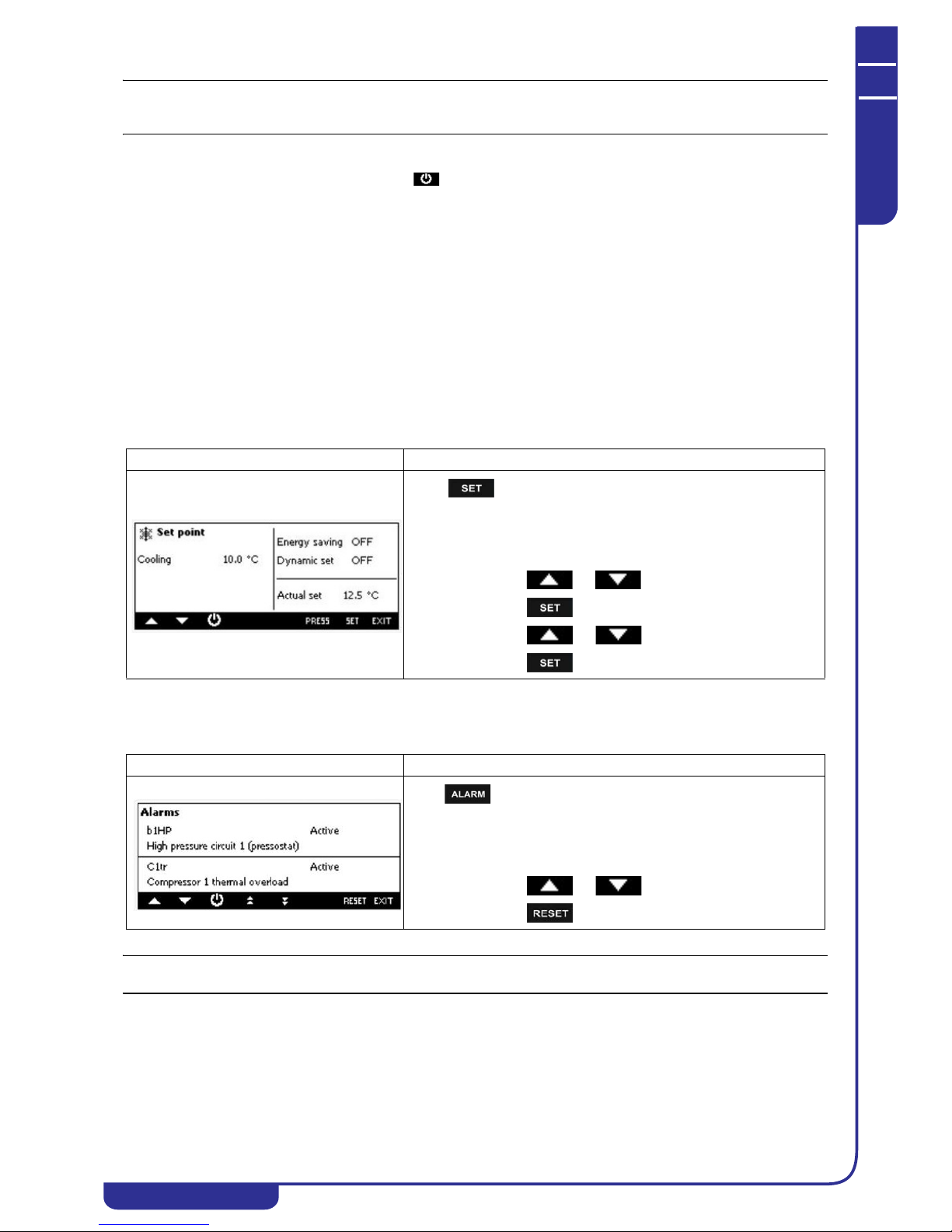
OPERATING AND MAINTENANCE MANUAL
Chapter 7 - Electronic controller
TAEevo Tech 015÷802 60 Hz UL
64
The data in this manual are not binding and they can be modified by the manufacturer without notice. Reproduction of this manual is strictly prohibited
ENGLISH
EN
NOTE
In case of a power loss, when pow er is restored the unit will be ON if it was ON at the time of power loss, and OFF if it was
OFF.
7.25.1 Start from the ke ypad
From unit OFF (stand-by) press and release button to switch the unit on or off in chiller mode. With the unit ON the
controller shows unit ON on the display.
Stand-by mode is set each time the unit is switched off from chiller operating mode. Also in stand-by the controller makes it
possible to:
• Display the measured values.
• Manage the alarm situation by displaying and signalling active alarms.
7.25.2 Start-up from a d igital input
The unit can be switched on/off from a digital input configured as remote On/OFF.
The power-off command (local or remote) always assumes priority with respect to the power-on command. If the unit is
powered-off with a local command it must be powered back on with a local command.
When the unit is in OFF status from a digital input the controller shows unit OFF on the display.
For details concerning the connection, refer to the electrical diagram.
7.26 Visualization / modification of the set point
7.27 Alarm visualization
NOTE
In case of alarm the pressure of any key silences the alarm.
Mask Description
Press key to read the value of the set point .
It is also possible to read the status of the Energy saving, the status of the
Dynamic set point and the real value of the set point if the Energy saving
or Dinamic set point are active.
To modify the set point (Cooling):
• press or to select the value of the set point
• press
• press or to modify the value
• press .to confirm the operation
Mask Description
Press key to read the alarm status; the alarm status can be:
• Active: the alarm is still active and it is not possible to
reset it
• Reset: the alarm is not active and it is possible to reset it.
Manual reset procedure:
• press or to select the alarm;
• press to reset the alarm
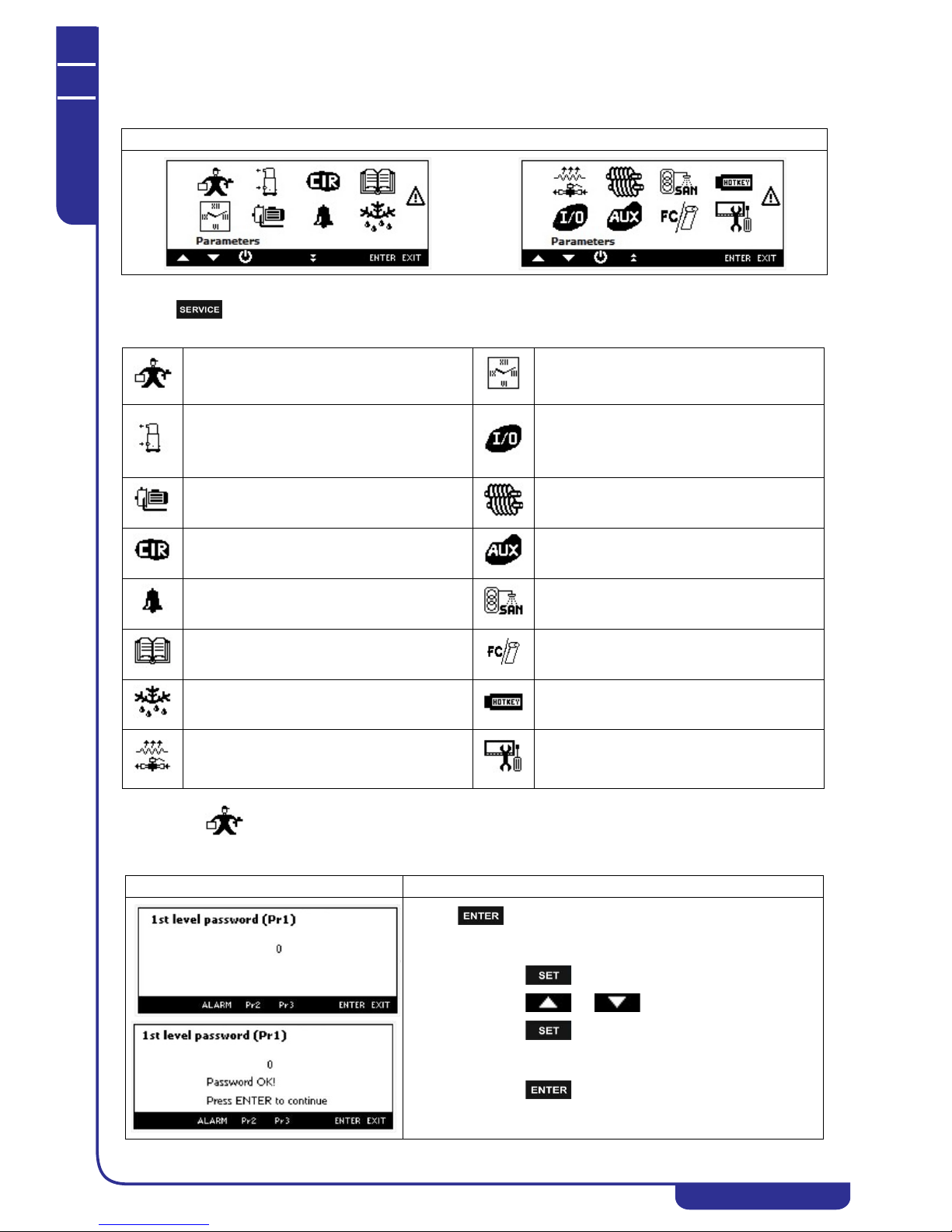
OPERATING AND MAINTENANCE MANUAL
Chapter 7 - Electronic controller
TAEevo Tech 015÷802 60 Hz UL
65
The data in this manual are not binding and they can be modified by the manufacturer without notice. Reproduction of this manual is strictly prohibited
EN
ENGLISH
7.28 Menu service visualization
Pressing it is possible to read the following information:
7.29 Parameters programming
Mask
Parameter programming
Programming clock
Energy saving and ON/OFF scheduling (Function not
available)
Compressor maintenance
It is possible to disable the compressor for
maintenance, read the working hours and number
of start up (and reset them)
I/O status
Water pump maintenance
It is possible to read / reset the working hours
Screw compressor information (Function not
available)
Circuit maintenance Auxiliary output status
Visualization and reset of the alarms
Sanitary water status, sanitary water temperature,
antilegionella status, etc. (Function not available)
Visualization and reset of the alarm log
Free cooling and Solar panel visualization (Function
not available)
Defrost status (Function not available) Upload e Download mappa parametri con Hot Key
Electrical heater
Visograph configuration
It is possible to change the language, to set the
contrast and the backlight.
Mask Description
Pressing it is possible to read/modify the parameters value:
• select the level 1 (default) or level 2 or level (by pressing
Pr2 or Pr3 key)
• press
• press or to enter the password
• press to confirm.
• the display shows "Password OK!" (otherwise repeat the
procedure)
• press to visualize the parameters.
If the value of the password is incorrect, the display will remain in
setting passwords and will be replayed the steps listed above.

OPERATING AND MAINTENANCE MANUAL
Chapter 7 - Electronic controller
TAEevo Tech 015÷802 60 Hz UL
66
The data in this manual are not binding and they can be modified by the manufacturer without notice. Reproduction of this manual is strictly prohibited
ENGLISH
EN
7.30 Compressor maintenance
Pressing it is possible to visualize the compressor working hour and the number of activations.
It is also possible to disable the compressor for maintenance.
Pressing in correspondence of the circuit 1 or circuit 2 allows access to the compressors of the circuit.
7.31 Water pump maintenance
Mask Description
Pressing or it is possible to select the group of
parameters to modify, then press .
How to modify the value of the parameter:
• press or to select the parameter to
modify
• press
• press or to modify the value
• press to confirm.
Press or to scroll the parameters.
Mask Description
How to reset the working hours and number of start up:
• press or to select the label RST;
• press for 5 seconds to reset hour and start up.
How to disable a compressor:
• press or to select the status of the
compressor (Enabled in the "Status" column);
• press for 5 seconds
• press or to select the status "Disabled"
• press for 5 seconds to confirm the operation.
Mask Description
How to reset the working hours:
• press or to select the label RST;
• press for 5 seconds to reset hour and start up.
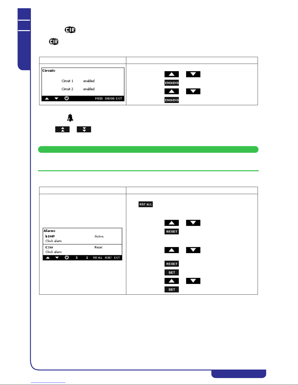
OPERATING AND MAINTENANCE MANUAL
Chapter 7 - Electronic controller
TAEevo Tech 015÷802 60 Hz UL
67
The data in this manual are not binding and they can be modified by the manufacturer without notice. Reproduction of this manual is strictly prohibited
EN
ENGLISH
7.32 Circuit maintenance
Press to disable the circuit for maintenance; all the compressor will be switched off after disabling the circuit.
7.33 Alarm visualization and reset
Pressing or it is possible to visualize the alarms; the alarm status can be:
• Active: the alarm is still active and it is not possible to reset it
• Reset: the alarm is not active and it is possible to reset it
ATTENTION
With this procedure you can reset all the alarms except for the compressor thermal cut-out alarms for which the
password will be required: 14.
Mask Description
How to disable a circuit:
• press or to select the circuit to disable
• press for 5 seconds
• press or to select the status "Disabled"
• press for 5 seconds to confirm the operation
Mask Description
Manual reset of all alarms:
press to reset all the alarms (only the alarms that are not active)
Manual reset procedure:
• press or to select the alarm;
• press to reset the alarm.
In case of compressor overload alarm when the password is requested,
operate in this way:
• press or to select the compressor
overload alarm
• press
• press
• press or to insert the password value
• press to confirm the operation
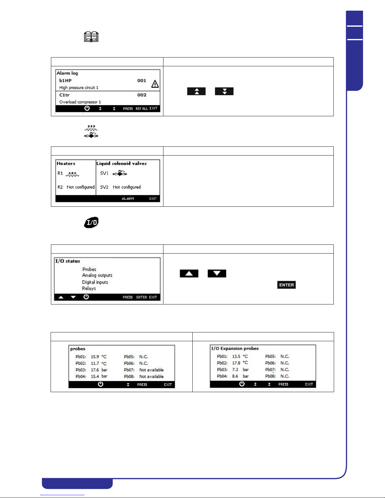
OPERATING AND MAINTENANCE MANUAL
Chapter 7 - Electronic controller
TAEevo Tech 015÷802 60 Hz UL
68
The data in this manual are not binding and they can be modified by the manufacturer without notice. Reproduction of this manual is strictly prohibited
ENGLISH
EN
7.34 Alarm log visualization
7.35 Electric heater visualization
7.36 I/O status
Display of temperatures and pressures measured by the probes configured.
Mask Description
Pressing or it is possible to read all stored alarms.
Mask Description
It is possible to read the status of the electrical heaters.
Mask Description
Press or to select the digital input, probes value,
analog output, digital input or relays, then press .
• Probe of the control • Probes Ex pansion I/O (if con figured)

OPERATING AND MAINTENANCE MANUAL
Chapter 7 - Electronic controller
TAEevo Tech 015÷802 60 Hz UL
69
The data in this manual are not binding and they can be modified by the manufacturer without notice. Reproduction of this manual is strictly prohibited
EN
ENGLISH
Viewing the status of the digital inputs
Viewing the status of the relays:
7.37 Auxiliary output visualization
• Probes Expansion I/O (if configured)
• Probes of the electronic expansion valve (if
configured)
• Display of values / state of the analog outputs
• Digital inputs of the control • I nputs of digital I/O extension (if configured)
• Relays of the control • Relay I/O extension (if configured)
Mask Description
Press or to select the auxiliary relay or analog output
and press to read the information (probe value, status of the
output).
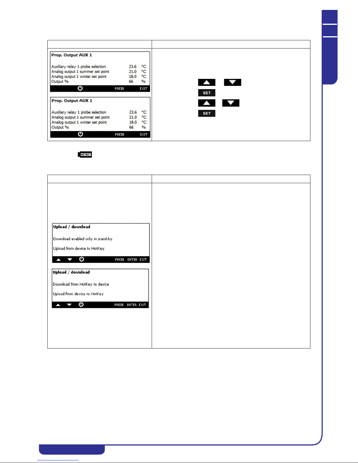
OPERATING AND MAINTENANCE MANUAL
Chapter 7 - Electronic controller
TAEevo Tech 015÷802 60 Hz UL
70
The data in this manual are not binding and they can be modified by the manufacturer without notice. Reproduction of this manual is strictly prohibited
ENGLISH
EN
7.38 Parameters programming with Hot Key
Mask Description
To view / modify the set point of operation of the analog outputs:
• press or to select the set point
• press
• press o to modify the value
• press to confirm the operation
Mask Description
It is possible to use the HotKey 64 for:
• copy the parameter map from the HotKey 64 to the control
(Download)
• copy the parameter map from the control to HotKey 64
(Upload)
Download from HotKey 64 to control:
this operation is enabled only if the control is in STD-BY or remote OFF,
otherwise the display shows the message "Download enabled only in
stand-by".
Download procedure:
• Insert the Hot Key 64 into the 5 ways connector through
the hole at the top of the control (see image below)
• Select "Download from HotKey to device"
• Press ENTER
• if the operation was successful the display shows "OK",
otherwise shows "ERR"
Upload from Ichill to Hot Key 64:
Upload procedure:
• Insert the Hot Key 64 into the 5 ways connector through
the hole at the top of the control (see image below)
• Select "Upload from device to HotKey"
• Press ENTER
• if the operation was successful the display shows "OK",
otherwise shows "ERR"
In case of Upload / Download failure:
• Hot Key 64 not properly inserted in the 5 ways connector
• Hot Key model different to Hot Key 64
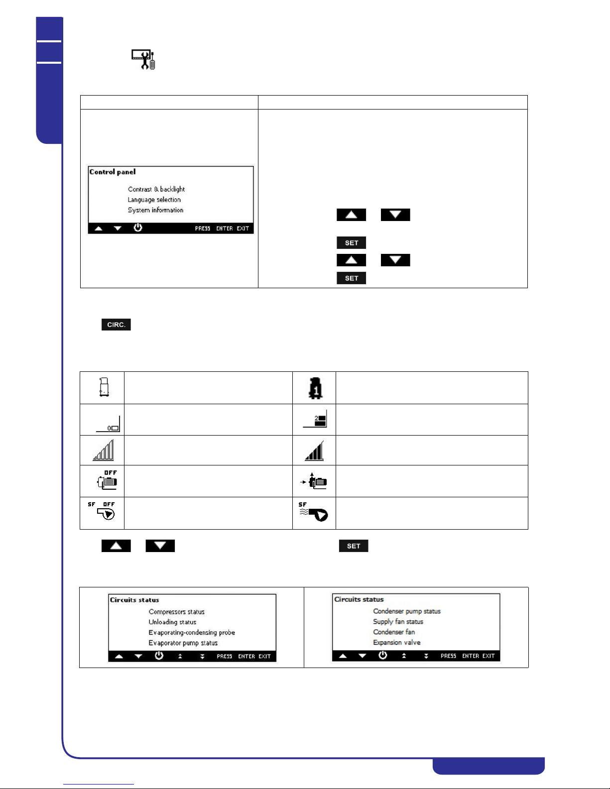
OPERATING AND MAINTENANCE MANUAL
Chapter 7 - Electronic controller
TAEevo Tech 015÷802 60 Hz UL
71
The data in this manual are not binding and they can be modified by the manufacturer without notice. Reproduction of this manual is strictly prohibited
EN
ENGLISH
7.39 Keyboard configuration
7.40 Circuit Information
Press to read the main information about the circuit of the compressor status, unloading status, evaporating condensing probes, water pump, condenser fan/valve status
Load status visualization:
Press or to select the information to read then press .
Circuits status
Mask Description
It is possible to set:
• contrast and backlight (it is strongly recommended to
reduce as possible the activation time of the backlight)
• language selection
• Ichill firmware release (to verify the compatibility control
Visograph keyboard)
• Visograph keyboard firmware release / Visograph
keyboard bin release.
How to modify the configuration:
• press or to select the configuration to
change
• press
• press or to change the configuration
• press to confirm.
Compressor OFF Compressor ON
Condenser fan OFF (step regulation)
(Function not available)
Condenser fan ON (step regulation) (Function not
available)
Condenser fan OFF (proportional regulation)
or condensation valve OFF
Condenser fan ON (proportional regulation) or
condensation valve OFF
Water pump OFF Water pump ON
Supply fan OFF (Function not available) Supply fan ON (Function not available)
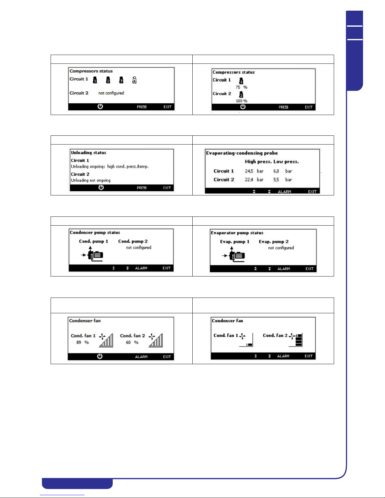
OPERATING AND MAINTENANCE MANUAL
Chapter 7 - Electronic controller
TAEevo Tech 015÷802 60 Hz UL
72
The data in this manual are not binding and they can be modified by the manufacturer without notice. Reproduction of this manual is strictly prohibited
ENGLISH
EN
Compressors status
• Compressors of ON/OFF type • Inverter compressors (not available)
Unloading status Evaporating and condensing probe reading
Condensator pump status Evaporator pump status
• Fans with speed control valves or
condensation
Condenser fan status
ON/OFF fan

OPERATING AND MAINTENANCE MANUAL
Chapter 7 - Electronic controller
TAEevo Tech 015÷802 60 Hz UL
73
The data in this manual are not binding and they can be modified by the manufacturer without notice. Reproduction of this manual is strictly prohibited
EN
ENGLISH
7.41 Parameters description-settings
The following is a list of all the programmable parameters complete with their associated access levels.
U= User level
S= Service level
C= Manufacturer level
ATTENTION
Ensure these instructions are observed in full to avoid incorrect operation of the unit.
7.41.1 Description of paramete rs
Parameter Level Description Min. Max. UM Resolution
Thermoregulator
ST01 U Chiller setpoint.
Enables setting of the working setpoint in chiller mode.
ST02 ST03 °C
°F
Dec
Int
ST02 U Chiller minimum set.
Establishes the minimum limit that can be utilised to set the
chiller working setpoint.
-50.0
-58
ST01 °C
°F
Dec
Int
ST03 C Chiller maximum set.
Establishes the maximum limit that can be utilised to set the
chiller working setpoint.
ST01 110.0
230°C°F
Dec
Int
ST04 C Heat pump setpoint.
Enables setting of the working setpoint in heat pump mode.
ST05 ST06 °C
°F
Dec
Int
ST05 C Heat pump minimum set.
Establishes the minimum limit that can be utilised to set the heat
pump working setpoint.
-50.0
-58
ST04 °C
°F
Dec
Int
ST06 C Heat pump maximum set.
Establishes the maximum limit that can be utilised to set the heat
pump working setpoint.
ST04 110.0
230°C°F
Dec
Int
ST07 U Control steps activation band in chiller mode. 0.1025.045°C
°F
Dec
Int
ST08 C Control steps activation band in heat pump mode. 0.1025.045°C
°F
Dec
Int
ST09 C Defines the probe for temperature control of the unit in chiller
mode:
0= Evaporator inlet NTC temperature probe
1= Evaporator outlet NTC temperature probe no. 1
2= Evaporator outlet NTC temperature probe no. 2
3= Common evaporator outlet NTC temperature probe
4= Remote terminal temperature probe no. 1
5= Remote terminal temperature probe no. 2
05

OPERATING AND MAINTENANCE MANUAL
Chapter 7 - Electronic controller
TAEevo Tech 015÷802 60 Hz UL
74
The data in this manual are not binding and they can be modified by the manufacturer without notice. Reproduction of this manual is strictly prohibited
ENGLISH
EN
ST10 C Defines the probe for temperature control of the unit in heat pump
mode:
0= Evaporator inlet NTC temperature probe
1= Evaporator outlet NTC temperature probe no. 1
2= Evaporator outlet NTC temperature probe no. 2
3= Common evaporator outlet NTC temperature probe
4= Remote terminal temperature probe no. 1
5= Remote terminal temperature probe no. 2
6= Common condenser water inlet NTC temperature probe
7= Circuit n° 1 condenser water inlet NTC temperature probe
8= Circuit n° 2 condenser water inlet NTC temperature probe
9= Circuit n° 1 condenser water outlet NTC temperature probe
10= Circuit n° 2 condenser water outlet NTC temperature probe
11= Common condenser water outlet NTC temperature probe
ATTENTION
If the same temperature control is required both in chiller
mode and in heat pump mode, set the same value in parameters
ST09 and ST10.
011
ST11 S Defines the temperature control type:
0= Proportional
1= Neutral zone
01
Pr1 U User password 0 999
Pr2 S Service password 0 999
Pr3 C Manufacturer password 0 999
Display message
dP01 S Upper display default presentation.
0= No visualization
1= Temperature probe of the evaporator water inlet (EIn label)
3= Temperature probe of the common evaporator water outlet
(EOut label)
016
dP02 S Lower display default presentation.
0= No visualization
1= Temperature probe of the evaporator water inlet (Label EIn)
3= Temperature probe of the common evaporator water outlet
(EOut label)
020
Forced display message
dP03 C Lower / upper display default presentation:
0= Configurable presentation
1= Upper display evaporator IN / lower display evaporator OUT
2= Upper display condenser IN / lower display condenser OUT
3= Upper display condensing temperature / pressure / lower
display evaporation pressure.
03
Remote terminals display forced presentation
dP04 C Remote terminal no.1 upper display default presentation:
0= The display mode depends on the value of parameters dP01 dP02 - dP03
1= The upper display shows the temperature measured by the
NTC probe on board remote terminal no.1
01
dP05 C Remote terminal no.2 upper display default presentation:
0= The display mode depends on the value of parameters dP01 dP02 - dP03
1= The upper display shows the temperature measured by the
NTC probe on board remote terminal no.2
01
dP06 S Visograph: first displayed probe selection 0 35
dP07 S Visograph: second displayed probe selection 0 35
dP08 S Visograph: third displayed probe selection 0 35
dP09 S Visograph: fourth displayed probe selection 0 35
Parameter Level Description Min. Max. UM Resolution

OPERATING AND MAINTENANCE MANUAL
Chapter 7 - Electronic controller
TAEevo Tech 015÷802 60 Hz UL
75
The data in this manual are not binding and they can be modified by the manufacturer without notice. Reproduction of this manual is strictly prohibited
EN
ENGLISH
Display presentation in STD-BY
dP10 S Ichill display presentation in STD-BY:
0= Shows label “STD-BY”
1= Shows parameters defined by par. dP1 and dP2
2= Shows label “OFF”
02
Pr1 U User password 0 999
Pr2 S Service passwo rd 0 999
Pr3 C Manufacturer password 0 999
Unit
CF01 C Defines the type of unit to control:
0= Air / air chiller
1= Air / water chiller
2= Water / water chiller
02
CF02 C Unit operation selection:
1= Chiller only
2= Heat pump only
3= Chiller with heat pump
13
CF03 C Condensing units:
0= No
1= Yes
01
Compressors
CF04 C Number of compressors present in ci rcuit no. 1:
1= 1 compressor
2= 2 compressors
3= 3 compressors
4= 4 compressors
14
CF05 C Number of compressors present in ci rcuit no. 2:
0= None
1= 1 compressor
2= 2 compressors
3= 3 compressors
03
CF06 C Number of capacity steps per compressor:
0= None
1= 1 step
2= 2 steps
3= 3 steps
03
Analogue inputs
CF07 C Operation in temperature or pressure fro m analogue input:
0= Operation in temperature / pressure NTC - 4...20 mA:
The condensing temperature is controlled via an NTC probe while
a transducer with 4..20mA output must be used for the
evaporation pressure control of circuits 1 and 2 and the pressure
probe configured as auxiliary output 1 and 2.
1= Operation in pressure with 4...20 mA input:
A transducer with 4..20mA output must be used to control the
condensing or evaporation pressures
2= Operation in temperature / pressure NTC - 0...5V:
The condensing temperature is controlled via an NTC probe while
a ratiometric transducer with 0..5V input must be used for the
evaporation pressure control of circuits 1 and 2 and the pressure
probe configured as auxiliary output 1 and 2.
3= Operation in pressure with 0...5V input:
A ratiometric transducer with 0..5V input must be used to control
the condensing or evaporation pressures.
03
CF08 C PB1 configuration
If configured as a digital input.
0
o 128c75
CF09 C PB2 configuration
If configured as a digital input.
0
o 128c75
CF10 C PB3 configuration
If configured as a digital input.
0
o 135c75
CF11 C PB4 configuration
If configured as a digital input.
0
o 135c75
Parameter Level Description Min. Max. UM Resolution

OPERATING AND MAINTENANCE MANUAL
Chapter 7 - Electronic controller
TAEevo Tech 015÷802 60 Hz UL
76
The data in this manual are not binding and they can be modified by the manufacturer without notice. Reproduction of this manual is strictly prohibited
ENGLISH
EN
CF12 C PB5 configuration
If configured as a digital input.
0
o 128c75
CF13 C PB6 configuration
If configured as a digital input.
0
o 128c75
CF14 C NOT USED 0 0
CF15 C NOT USED 0 0
Probes offset
CF16 S PB1 offset. -12.0
-21
12.021°C
°F
Dec
Int
CF17 S PB2 offset. -12.0
-21
12.021°C
°F
Dec
Int
CF18 S PB3 offset. -5.0
-72
5.072Bar
Psi
Dec
Int
CF19 S PB4 offset. -5.0
-72
5.072Bar
Psi
Dec
Int
CF20 S PB5 offset. -12.0
-21
12.021°C
°F
Dec
Int
CF21 S PB6 offset. -12.0
-21
12.021°C
°F
Dec
Int
CF22 S NOT USED 0 0
CF23 S NOT USED 0 0
CF24 C Transducer PB3 pressure value at 4mA - 0.5 V. -1.0
-14
50.0
725
Bar
Psi
Dec
Int
CF25 C Transducer PB3 pressure value at 20mA - 5 V. -1.0
-14
50.0
725
Bar
Psi
Dec
Int
CF26 C Transducer PB4 pressure value at 4mA - 0.5 V. -1.0
-14
50.0
725
Bar
Psi
Dec
Int
CF27 C Transducer PB4 pressure value at 20mA - 5 V. -1.0
-14
50.0
725
Bar
Psi
Dec
Int
CF28 C NOT USED 0 0
CF29 C NOT USED 0 0
Digital inputs
CF30 C ID1 configuration: 0 -o1 c75
CF31 C ID2 configuration: 0 -o1 c75
CF32 C ID3 configuration. 0 -o1 c75
CF33 C ID4 configuration. 0 -o1 c75
CF34 C ID5 configuration: 0 -o1 c75
CF35 C ID6 configuration. 0 -o1 c75
CF36 C ID7 configuration. 0 -o1 c75
CF37 C ID8 configuration. 0 -o1 c75
CF38 S ID9 configuratio n. 0 -o1 c75
CF39 C ID10 configuration. 0 -o1 c75
CF40 C ID11 configuration. 0 -o1 c75
Relay outputs
CF41 C RL1 configuration. 0 -o1 c74
CF42 C RL2 configuration. 0 -o1 c74
CF43 C RL3 configuration. 0 -o1 c74
CF44 C RL4 configuration: 0 -o1 c74
CF45 C RL5 configuration: 0 -o1 c74
CF46 C RL6 configuration. 0 -o1 c74
CF47 C RL7 configuration. 0 -o1 c74
CF48 C RL8 configuration. 0 -o1 c74
Condensing proportional outputs
CF49 C NOT USED
Modulating outputs
Parameter Level Description Min. Max. UM Resolution

OPERATING AND MAINTENANCE MANUAL
Chapter 7 - Electronic controller
TAEevo Tech 015÷802 60 Hz UL
77
The data in this manual are not binding and they can be modified by the manufacturer without notice. Reproduction of this manual is strictly prohibited
EN
ENGLISH
CF50 C Proportional output OUT 1:
0= Output disabled
1= Evaporator pump 0...10V with modulating operation
2= Modulating output 0...10V for Free cooling
3= Not used
4= 0...10V auxiliary output no. 1
5= 0...10V auxiliary output no. 2
6= 0...10V modulating output compressor 1 circuit no. 1
7= 0...10V modulating output compressor 1 circuit no. 2
8= Condensing fans 0...10V modulating output circuit no. 1
9= Condensing fans 0...10V modulating output circuit no. 2
Relay controlling ON / OFF output
0
o 19c50
CF51 C Proportional output OUT 2:
0= Output disabled
1= Evaporator pump 0...10V with modulating operation
2= Modulating output 0...10V for Free cooling
3= Not used
4= 0...10V auxiliary output no. 1
5= 0...10V auxiliary output no. 2
6= 0...10V modulating output compressor 1 circuit no. 1
7= 0...10V modulating output compressor 1 circuit no. 2
8= Condensing fans 0...10V modulating output circuit no. 1
9= Condensing fans 0...10V modulating output circuit no. 2
Relay controlling ON / OFF output
0
o 19c50
CF52 C Proportional output OUT 3:
0= Output disabled
1= Evaporator pump 0...10V with modulating operation
2= Modulating output 0...10V for Free cooling
3= Not used
4= 0...10V auxiliary output no. 1
5= 0...10V auxiliary output no. 2
6= 0...10V modulating output compressor 1 circuit no. 1
7= 0...10V modulating output compressor 1 circuit no. 2
8= Condensing fans 0...10V modulating output circuit no. 1
9= Condensing fans 0...10V modulating output circuit no. 2
10= Condensing fans phase chopping modulating output circuit
no. 1
11= Condensing fans phase chopping modulating output circuit
no. 2
Relay controlling ON / OFF output
0
o 111c50
CF53 C Proportional output OUT 4:
0= Output disabled
1= Evaporator pump 0...10V with modulating operation
2= Modulating output 0...10V for Free cooling
3= Not used
4= 0...10V auxiliary output no. 1
5= 0...10V auxiliary output no. 2
6= 0...10V modulating output compressor 1 circuit no. 1
7= 0...10V modulating output compressor 1 circuit no. 2
8= Condensing fans 0...10V modulating output circuit no. 1
9= Condensing fans 0...10V modulating output circuit no. 2
10= Condensing fans phase chopping modulating output circuit
no. 1
11= Condensing fans phase chopping modulating output circuit
no. 2
Relay controlling ON / OFF output
0
o 111c50
Remote terminal
CF54 U Configuration of remote terminal no. 1:
0= Absent
1= On board NTC probe
2= Without on board NTC probe
02
Parameter Level Description Min. Max. UM Resolution

OPERATING AND MAINTENANCE MANUAL
Chapter 7 - Electronic controller
TAEevo Tech 015÷802 60 Hz UL
78
The data in this manual are not binding and they can be modified by the manufacturer without notice. Reproduction of this manual is strictly prohibited
ENGLISH
EN
CF55 C Configuration of remote terminal no. 2:
0= Absent
1= On board NTC probe
2= Without on board NTC probe
02
CF56 C Remote terminal no. 1 NTC probe offset. -12.0
-21
12.021°C
°F
Dec
Int
CF57 C Remote terminal no. 2 NTC probe offset. -12.0
-21
12.021°C
°F
Dec
Int
Operating logic
CF58 C Operating logic:
0=
chiller / heat pump
1= chiller / heat pump
01
Chiller / heat pump mode selection
CF59 C Chiller / heat pump mode selection:
0= From keypad
1= From digital input
2= From analogue input
02
Automatic change-over
CF60 C Chiller / heat pump operation automatic changeover set if
parameter CF80=2.
-50.0
-58
110.0
230°C°F
Dec
Int
CF61 C Chiller / heat pump operation automatic changeover differential if
parameter CF80=2.
0.1025.045°C
°F
Dec
Int
Unit of measurement selection
CF62 C °C or °F selection:
0= °C / BAR
1 = °F / psi
01
Mains frequency selection
CF63 S Mains frequency selection:
0= 50 Hz
1= 60 Hz
2= Continuous power input (to use if the PWM outputs for control
of the condensing fans are not used)
02
Serial address
CF64 U Serial address. 1 247
CF65 C Firmware release
CF66 C Eeprom parameters 0 999
Temperature control of compressors with different cooling capacity
CF67 C Compressor 1 capacity 0 100%
CF68 C Compressor 2 capacity 0 100%
CF69 C Compressor 3 capacity 0 100%
CF70 C Compressor 4 capacity 0 100%
CF71 C NOT USED 0 0
CF72 C NOT USED 0 0
CF73 C Maximum number of compressor starts after 15 minutes ON:
0 = Function disabled
015
Compressors operation enabling
CF74 C Selection of compressors operation enabling:
0= Chiller and heat pump
1= Chiller only
2= Heat pump only
02
Enabling of units with hybrid exchangers
CF75 C Enabling of units with hybri d exchangers:
1= Enabled
01
Buzzer enabling
CF76 C Buzzer enabling:
0= Disabled
1= Enabled
01
Parameter Level Description Min. Max. UM Resolution
OPERATING AND MAINTENANCE MANUAL
Chapter 7 - Electronic controller
TAEevo Tech 015÷802 60 Hz UL
79
The data in this manual are not binding and they can be modified by the manufacturer without notice. Reproduction of this manual is strictly prohibited
EN
ENGLISH
Chiller mode
CF77 C Chiller mode:
1= With compressors
2= Only FC
3= With compressors and FC
13
I/O expansion enabling
CF78 C I/O expansion enabling:
0= Not enabled
1= Enabled
01
Electronic expansion valve driver enabling
CF79 C Circuit 1 electronic expansion valve enabling:
0= Not enabled
1= Enabled
01
CF80 C Circuit 2 electronic expansion valve enabling:
0= Not enabled
1= Enabled
01
CF81 C Electronic expansion valve address 1 15
CF82 C Evaporation probe positioning selection:
0= In Ichill controller
1= In IEV valve driver
01
CF83 C Temperature control start delay after transmitting valve start
command
0 250 Sec.
CF84 C Visograph keypad presence:
0= No
1= Yes
01
I/O expansion configuration
EI01 C I/O expansion board address 0 15
EI02 C PB1 configuration
If configured as a digital input.
0
o 128c75
EI03 C PB2 configuration
If configured as a digital input.
0
o 128c75
EI04 C PB3 configuration
If configured as a digital input.
0
o 135c75
EI05 C PB4 configuration
If configured as a digital input.
0
o 135c75
EI06 C PB5 configuration
If configured as a digital input.
0
o 135c75
EI07 C PB6 configuration
If configured as a digital input.
0
o 128c75
EI08 C PB7 configuration
If configured as a digital input.
0
o 128c75
EI09 C PB8 configuration
If configured as a digital input.
0
o 128c75
I/O expansion probes offset
EI10 C PB1 offset -12.0
-21
12.021°C
°F
Dec
Int
EI11 C PB2 offset -12.0
-21
12.021°C
°F
Dec
Int
EI12 C PB3 offset -5.0
-72
5.072Bar
Psi
Dec
Int
EI13 C PB4 offset -5.0
-72
5.072Bar
Psi
Dec
Int
EI14 C PB5 offset -12.0
-21
12.021°C
°F
Dec
Int
EI15 C PB6 offset -12.0
-21
12.021°C
°F
Dec
Int
EI16 C PB7 offset -12.0
-21
12.021°C
°F
Dec
Int
EI17 C PB8 offset -12.0
-21
12.021°C
°F
Dec
Int
Parameter Level Description Min. Max. UM Resolution

OPERATING AND MAINTENANCE MANUAL
Chapter 7 - Electronic controller
TAEevo Tech 015÷802 60 Hz UL
80
The data in this manual are not binding and they can be modified by the manufacturer without notice. Reproduction of this manual is strictly prohibited
ENGLISH
EN
EI18 C Transducer PB3 pressure value at 4mA - 0.5V. -1.0
-14
50.0
725
Bar
Psi
Dec
Int
EI19 C Transducer PB3 pressure value at 20mA - 4.5V. -1.0
-14
50.0
725
Bar
Psi
Dec
Int
EI20 C Transducer PB4 pressure value at 4mA - 0.5V. -1.0
-14
50.0
725
Bar
Psi
Dec
Int
EI21 C Transducer PB4 pressure value at 20mA - 4.5V. -1.0
-14
50.0
725
Bar
Psi
Dec
Int
EI22 C Transducer PB5 pressure value at 4mA - 0.5V. -1.0
-14
50.0
725
Bar
Psi
Dec
Int
EI23 C Transducer PB5 pressure value at 20mA - 4.5V. -1.0
-14
50.0
725
Bar
Psi
Dec
Int
I/O expansion digital inputs
EI24 C ID1 configuration 0 -o1 c75
EI25 C ID2 configuration 0 -o1 c75
EI26 C ID3 configuration 0 -o1 c75
EI27 C ID4 configuration 0 -o1 c75
EI28 C ID5 configuration 0 -o1 c75
EI29 C ID6 configuration 0 -o1 c75
EI30 C ID7 configuration 0 -o1 c75
EI31 C ID8 configuration 0 -o1 c75
EI32 C ID9 configuration 0 -o1 c75
I/O expansion relay inputs
EI33 C RL1 configuration 0 -o1 c74
EI34 C RL2 configuration 0 -o1 c74
EI35 C RL3 configuration 0 -o1 c74
EI36 C RL4 configuration 0 -o1 c74
EI37 C RL5 configuration 0 -o1 c74
EI38 C RL6 configuration 0 -o1 c74
EI39 C RL7 configuration 0 -o1 c74
I/O expansion proportional outputs
Modulating outputs
EI40 C Selection of analogue outputs signal 0..10V or 4..20mA 0 1
EI41 C Proportional output OUT 1:
0= Output disabled
1= Evaporator pump with modulating operation
2= Modulating output for Free cooling
3= Not used
4= 0...10V auxiliary output no. 1
5= 0...10V auxiliary output no. 2
6= Modulating output compressor 1 circuit no. 1
7= Modulating output compressor 1 circuit no. 2
8= 0...10V condensing fans circuit no. 1
9= 0...10V condensing fans circuit no. 2
Relay controlling ON / OFF output
0
o 19c50
EI42 C Proportional output OUT 2:
0= Output disabled
1= Evaporator pump with modulating operation
2= Modulating output for Free cooling
3= Not used
4= 0...10V auxiliary output no. 1
5= 0...10V auxiliary output no. 2
6= Modulating output compressor 1 circuit no. 1
7= Compressor 1 modulating output circuit no. 2
8= 0...10V condensing fans circuit no. 1
9= 0...10V condensing fans circuit no. 2
10= Condensing fans PWM output circuit 1
11= Condensing fans PWM output circuit 2
Relay controlling ON / OFF output
0
o 111c50
Parameter Level Description Min. Max. UM Resolution
OPERATING AND MAINTENANCE MANUAL
Chapter 7 - Electronic controller
TAEevo Tech 015÷802 60 Hz UL
81
The data in this manual are not binding and they can be modified by the manufacturer without notice. Reproduction of this manual is strictly prohibited
EN
ENGLISH
EI43 C Proportional output OUT 3:
0= Output disabled
1= Evaporator pump with modulating operation
2= Modulating output for Free cooling
3= Not used
4= 0...10V auxiliary output no. 1
5= 0...10V auxiliary output no. 2
6= Modulating output compressor 1 circuit no. 1
7= Modulating output compressor 1 circuit no. 2
8= 0...10V condensing fans circuit no. 1
9= 0...10V condensing fans circuit no. 2
10= Condensing fans PWM output circuit 1
11= Condensing fans PWM output circuit 2
Relay controlling ON / OFF output
0
o 111c50
Pr1 U User password 0 999
Pr2 S Service password 0 999
Pr3 C Manufacturer password 0 999
Dynamic setpoint
Sd01 U Dynamic setpoint max increase in chiller mode
Establishes the maximum variation of the working setpoint in
chiller mode.
-30.0
-54
30.054°C
°F
Dec
Int
Sd02 C Max dynamic setpoint increase in heat pump mode
Establishes the maximum variation of the working setpoint in
heat pump mode.
-30.0
-54
30.054°C
°F
Dec
Int
Sd03 U Dynamic setpoint ambient air temperature setting in chiller mode. -50.0
-58
110.0
230°C°F
Dec
Int
Sd04 C Dynamic setpoint ambient air temperature setting in heat pump
mode.
-50.0
-58
110.0
230
°C
°F
Dec
Int
Sd05 U Dynamic setpoint ambient air temperature differential in chiller
mode.
-30.0
-54
30.054°C
°F
Dec
Int
Sd06 C Dynamic setpoint ambient air temperature differential in heat
pump mode.
-30.0
-54
30.054°C
°F
Dec
Int
Sd07 C Dynamic setpoint max increase in chiller mode auxiliary
analogue output 1.
-30.0
-54
30.054°C
°F
Dec
Int
Sd08 C Dynamic setpoint max increase in heat pump mode auxiliary
analogue output 1.
-30.0
-54
30.054°C
°F
Dec
Int
Sd09 C Dynamic setpoint ambient air temperature setting in chiller mode
auxiliary analogue output 1.
-50.0
-58
110.0
230
°C
°F
Dec
Int
Sd10 C Dynamic setpoint ambient air temperature setting in heat pump
mode auxiliary analogue output 1.
-50.0
-58
110.0
230
°C
°F
Dec
Int
Sd11 C Dynamic setpoint ambient air temperature differential in chiller
mode auxiliary analogue output 1.
-30.0
-54
30.054°C
°F
Dec
Int
Sd12 C Dynamic setpoint ambient air temperature differential in heat
pump mode auxiliary analogue output 1.
-30.0
-54
30.054°C
°F
Dec
Int
Sd13 C Dynamic setpoint max increase in chiller mode auxiliary
analogue output 2.
-30.0
-54
30.054°C
°F
Dec
Int
Sd14 C Dynamic setpoint max increase in heat pump mode auxiliary
analogue output 2.
-30.0
-54
30.054°C
°F
Dec
Int
Sd15 C Dynamic setpoint ambient air temperature setting in chiller mode
auxiliary analogue output 2.
-50.0
-58
110.0
230
°C
°F
Dec
Int
Sd16 C Dynamic setpoint ambient air temperature setting in heat pump
mode auxiliary analogue output 2.
-50.0
-58
110.0
230
°C
°F
Dec
Int
Sd17 C Dynamic setpoint ambient air temperature differential in chiller
mode auxiliary analogue output 2.
-30.0
-54
30.054°C
°F
Dec
Int
Sd18 C Dynamic setpoint ambient air temperature differential in heat
pump mode auxiliary analogue output 2.
-30.0
-54
30.054°C
°F
Dec
Int
Sd19 C Dynamic setpoint max increase in chiller mode auxiliary relay 1. -30.0
-54
30.054°C
°F
Dec
Int
Sd20 C Dynamic setpoint max increase in heat pump mode auxiliary
relay 1.
-30.0
-54
30.054°C
°F
Dec
Int
Parameter Level Description Min. Max. UM Resolution
OPERATING AND MAINTENANCE MANUAL
Chapter 7 - Electronic controller
TAEevo Tech 015÷802 60 Hz UL
82
The data in this manual are not binding and they can be modified by the manufacturer without notice. Reproduction of this manual is strictly prohibited
ENGLISH
EN
Sd21 C Dynamic setpoint ambient air temperature setting in chiller mode
auxiliary relay 1.
-50.0
-58
110.0
230
°C
°F
Dec
Int
Sd22 C Dynamic setpoint ambient air temperature setting in heat pump
mode auxiliary relay 1.
-50.0
-58
110.0
230
°C
°F
Dec
Int
Sd23 C Dynamic setpoint ambient air temperature differential in chiller
mode auxiliary relay 1.
-30.0
-54
30.054°C
°F
Dec
Int
Sd24 C Dynamic setpoint ambient air temperature differential in heat
pump mode auxiliary relay 1.
-30.0
-54
30.054°C
°F
Dec
Int
Sd25 C Dynamic setpoint max increase in chiller mode auxiliary relay 2. -30.0
-54
30.054°C
°F
Dec
Int
Sd26 C Dynamic setpoint max increase in heat pump mode auxiliary
relay 2.
-30.0
-54
30.054°C
°F
Dec
Int
Sd27 C Dynamic setpoint ambient air temperature setting in chiller mode
auxiliary relay 2.
-50.0
-58
110.0
230
°C
°F
Dec
Int
Sd28 C Dynamic setpoint ambient air temperature setting in heat pump
mode auxiliary relay 2.
-50.0
-58
110.0
230
°C
°F
Dec
Int
Sd29 C Dynamic setpoint ambient air temperature differential in chiller
mode auxiliary relay 2.
-30.0
-54
30.054°C
°F
Dec
Int
Sd30 C Dynamic setpoint ambient air temperature differential in heat
pump mode auxiliary relay 2.
-30.0
-54
30.054°C
°F
Dec
Int
Pr1 U User password 0 999
Pr2 S Service password 0 999
Pr3 C Manufacturer password 0 999
Energy saving
ES01 C Start of operating band no. 1 (0...24) . 0 24.00 Hours 1 0 Min
ES02 C End of operating band no. 1 (0...24). 0 24.00 by Hours 10 Min
ES03 C Start of operating band no. 2 (0...24) . 0 24.00 by Hours 1 0 Min
ES04 C End of operating band no. 2 (0...24). 0 24.00 by Hours 10 Min
ES05 C Start of operating band no. 3 (0...24) . 0 24.00 by Hours 1 0 Min
ES06 C End of operating band no. 3 (0...24). 0 24.00 by Hours 10 Min
ES07 C Monday operation with time band in energy saving
Monday operation with automatic start / stop.
0 - 0 7 - 7
ES08 C Tuesday operation with time band in energy saving
Tuesday operation with automatic start / stop.
0 - 0 7 - 7
ES09 C Wednesday operation with time band in energy saving
Wednesday operation with automatic start / stop.
0 - 0 7 - 7
ES10 C Thursday operation with time band in energy saving
Thursday operation with automatic start / stop.
0 - 0 7 - 7
ES11 C Friday operation with time band in energy saving
Friday operation with automatic start / stop.
0 - 0 7 - 7
ES12 C Saturday operation with time band in energy sav ing
Saturday operation with automatic start / stop.
0 - 0 7 - 7
ES13 C Sunday operation with time band in energy saving
Sunday operation with automatic start / stop.
0 - 0 7 - 7
ES14 C Energy saving setting increase in chiller mode. -30.0
-54
30.054°C
°F
Dec
Int
ES15 C Energy saving differential in chiller mode. 0.1025.045°C
°F
Dec
Int
ES16 C Energy saving setting increase in heat pump mode. -30.0
-54
30.054°C
°F
Dec
Int
ES17 C Energy saving differential in heat pump mode. 0.1025.045°C
°F
Dec
Int
ES18 C Maximum operating time of unit in OFF from RTC if forced ON
from button.
1 250 10 Min Min.
ES19 C Start of time band 1 - domestic hot water (0...24) 0 24.00 by Hours 10 Min
ES20 C End of time band 1 - domestic hot water (0...24) 0 24.00 by Hours 10 Min
ES21 C Start of time band 2 - domestic hot water (0...24) 0 24.00 by Hours 10 Min
ES22 C End of time band 2 - domestic hot water (0...24) 0 24.00 by Hours 10 Min
ES23 C Start of time band 3 - domestic hot water (0...24) 0 24.00 by Hours 10 Min
Parameter Level Description Min. Max. UM Resolution
OPERATING AND MAINTENANCE MANUAL
Chapter 7 - Electronic controller
TAEevo Tech 015÷802 60 Hz UL
83
The data in this manual are not binding and they can be modified by the manufacturer without notice. Reproduction of this manual is strictly prohibited
EN
ENGLISH
ES24 C End of time band 3 - domestic hot water (0...24) 0 24.00 by Hours 10 Min
ES25 C Monday: energy saving active
Monday operation with domestic hot water time band
07
ES26 C Tuesday operation with domestic hot water time band 0 7
ES27 C Wednesday operation with domestic hot water time band 0 7
ES28 C Thursday operation with domestic hot water time band 0 7
ES29 C Friday operation with domestic hot water time band 0 7
ES30 C Saturday operation with domestic hot water time band 0 7
ES31 C Sunday operation with domestic hot water time band 0 7
ES32 C Domestic hot water energy saving setting increase -30.0
-54
30.054°C
°F
Dec
Int
ES33 C Domestic hot water differential in time band/digital input 0.1025.045°C
°F
Dec
Int
Pr1 U User password 0 999
Pr2 S Service password 0 999
Pr3 C Manufacturer password 0 999
Compressors plant
Cr01 C Defines the cooling plant temperature control type:
0= Disabled
1= Control with probe defined by ST09
2= Enabled with suction probe (evaporation) (condensing units
and heat pumps are automatically disabled)
02
Cr02 C Suction probe compressors setpoint (evaporation)
Makes it possible to program the working setpoint of the suction
probe
Cr03 Cr04 Bar
Psi
Dec
Int
Cr03 C Suction probe compressors minimum setting (evaporation)
Establishes the minimum limit that can be utilised to set the
suction probe working setpoint.
0 Cr02 Bar
Psi
Dec
Int
Cr04 C Suction probe compressors maximum setting (evaporation)
Establishes the maximum limit that can be utilised to set the
suction probe working setpoint.
Cr02 50
725
Bar
Psi
Dec
Int
Cr05 C Control steps activation band of suction probe. 0.1114.0
203
Bar
Psi
Dec
Int
Cr06 C Energy saving setting increase in cooling plant mode. 0.0014.0
203
Bar
Psi
Dec
Int
Cr07 C Energy saving differential in cooling plant mode. 0.1114.0
203
Bar
Psi
Dec
Int
Cr08 C No. of compressors to start in case of fault of probe allocated for
their control 0 ... 6
06
Cr09 C No. of condensing fan steps of the circuit to activate in case of
fault of probe allocated for their control 0 ... 4
04
Compressor
CO01 C Compressor minimum run time.
Establishes the time during which the compressor must run after
being starting, even if the demand drops.
0 250 10 Sec 10 Seconds
CO02 C Compressors minimum stop time.
Establishes the time during which the compressor must remain
stopped, even if restarting is requested.
During this period the compressor LED will flash.
0 250 10 Sec 10 Seconds
CO03 C Time lag between starts of 2 compressors / capacity steps.
With two compressors, establishes the starting time lag between
the two in order to limit starting peak current.
During this period the compressor LED will flash (only for the
compressor).
With unit having one capacity controlled compressor.
Establishes the activation time of the capacity control solenoid
for a start at minimum capacity (see heading “7.15.1 Compressors
control”).
1 250 Sec
Parameter Level Description Min. Max. UM Resolution
OPERATING AND MAINTENANCE MANUAL
Chapter 7 - Electronic controller
TAEevo Tech 015÷802 60 Hz UL
84
The data in this manual are not binding and they can be modified by the manufacturer without notice. Reproduction of this manual is strictly prohibited
ENGLISH
EN
CO04 C Time lag between stops of 2 compressors / capacity steps.
Establishes the stopping time lag between two compressors or
two capacity steps.
0250Sec
CO05 C Delay at compressors starting from power ON.
Starting construed as physical power-up of the controller.
Delays activation of all the outputs to distribute current draw and
protect the compressor(s) from repeated starts in the event of
frequent mains power losses.
0 250 10 Sec 10 Seconds
Capacity controls (INACTIVE FUNCTION)
CO06 C Capacity controls operation:
0= ON/OFF steps control
1= Direct action continuous run with capacity steps
2= Reverse action continuous run with capacity steps
3= Global continuous capacity step control
03
CO07 C Enabling for operation of minimum compressor capacity /
unloaded starting management:
0= Enables minimum capacity only at compressor start (start with
minimum capacity / unloaded starting with valve OFF and
compressor stopped)
1= Enables minimum capacity only at compressor start and during
temperature control (start with minimum capacity / unloaded
starting with valve OFF and compressor stopped)
2= Screw compressors, enables minimum capacity only at
compressor start (start with minimum capacity / unloaded starting
with valve ON and compressor stopped)
3= Screw compressors, enables minimum capacity at compressor
start and during temperature control (start with minimum capacity
/ unloaded starting with valve ON and compressor stopped)
03
CO08 C Screw compressor intermittent valve control relay ON time; if
parameter value is 0 the function is disabled.
0250Sec
CO09 C Screw compressor intermittent valve control relay OFF time. 0 250 Sec
Compressor starting
CO10 C Compressor starting (see heading “7.15.1 Compressors control”):
0= Direct
1= Part-winding
01
CO11 CIf CO10=1 part-winding starting time. Used to vary the
energization of the two different relays that feed the two motor
windings.
0 100 Dec Sec 0.1 Sec
CO12 C Time for which condensation fan thermal protection switch is
bypassed after controller power on
0250Sec
CO13 C Run time with gas by-pass valve / compressor unloaded starting
valve (see capacity controls operation).
0250Sec
Compressors rotation - balancing - temperature control
CO14 S Compressors rotation (see heading “7.15.6 Compressors
rotation”):
0= Fixed sequence
1= Rotation enabled with compressors temperature control on
basis of running hours
2= Rotation enabled with compressors temperature control on
basis of starts/hour (peak loads)
02
CO15 S Circuits balancing:
0= Circuits saturation
1= Circuits balancing
01
Parameter Level Description Min. Max. UM Resolution
OPERATING AND MAINTENANCE MANUAL
Chapter 7 - Electronic controller
TAEevo Tech 015÷802 60 Hz UL
85
The data in this manual are not binding and they can be modified by the manufacturer without notice. Reproduction of this manual is strictly prohibited
EN
ENGLISH
Evaporator water pump
CO16 S Evaporator pump / delivery fan operating mode:
0= Pump not installed and delivery fans not managed
1= Continuous operation; activation of the water pump / delivery
fan occurs when unit is powered on (chiller / heat pump mode
selection).
2= Operation on compressor request, starting and stopping of the
pump and delivery fan are linked to starting and stopping of the
compressor. In the case of an anti-freeze alarm the compressor
will stop and the pump will continue to run.
02
CO17 S Compressor ON time lag from start ing of pump / delivery fan. 1 250 Sec
CO18 S Evaporator water pump / delivery fan OFF time lack from
compressor stop. This time interval is observed also when the unit
is set to stand-by.
0 250 Min
CO19 U No. of hours for forced rotation of evaporator pumps. 0 999 10 Hours 10 Hours
CO20 S Simultaneous pumps run time after forced pumps rotation. 0 250 Sec
Condenser water pump
CO21 C Condenser pump operating mode:
0= Absent, pump is not managed
1= Continuous operation; starting and stopping of the pump
linked to starting and stopping of the unit
2= Operation on compressor request; starting and stopping of the
pump linked to starting and stopping of the compressor. In the
case of an anti-freeze alarm the compressor will stop and the
pump will continue to run.
02
CO22 CNot used 00
CO23 C Condenser pump OFF time lag from compressor stopping. This
time interval is observed also when the unit is set to stand-by.
0 250 Min
CO24 C No. of hours for forced rotation of condenser pumps. 0 999 10 Hours 10 Hour s
CO25 C Simultaneous pumps run time after forced rotation of condenser
pumps.
0 250 Sec
Maintenance of loads
CO26 S Compr essor 1 hour meter set. 0 999 10 Hours 10 Hours
CO27 S Compr essor 2 hour meter set. 0 999 10 Hours 10 Hours
CO28 S Compr essor 3 hour meter set. 0 999 10 Hours 10 Hours
CO29 S Compr essor 4 hour meter set. 0 999 10 Hours 10 Hours
CO30 C Compressor 5 hour meter set. 0 999 10 Hours 10 Hours
CO31 C Compressor 6 hour meter set. 0 999 10 Hours 10 Hours
CO32 S Pump / delivery fan hour meter set. 0 999 10 Hours 10 Hours
CO33 S Evap orator pump no. 2 hour meter set. 0 999 10 Hours 10 Hours
CO34 C Condenser pump hour meter set. 0 999 10 Hours 10 Hour s
CO35 C Condenser pump no. 2 hour meter set. 0 999 10 Hours 10 Hours
Pump down
CO36 C Pump-down operation:
0= Function disabled
1= Power off with pump-down without pump-down on starting
2= Power off with pump-down with pump-down on starting
3= Power off with pump-down only in chiller mode without
pump-down on starting
4= Power off with pump-down only in chiller mode with pumpdown on starting
04
CO37 C Pump-down pressure set. 0.0050.0
725
Bar
Psi
Dec
Int
CO38 C Pump-down pressure differential. 0.1112.0
174
Bar
Psi
Dec
Int
CO39 C Maximum holding time in pump-down in starting and in stopping. 0 250 Sec
Evaporator unloading
CO40 C Compressors unloading operation setpoint in chiller mode from
evaporator water inlet high temperature (see “7.16 Unloading
function”).
-50.0
-58
110.0
230
°C
°F
Dec
Int
Parameter Level Description Min. Max. UM Resolution
OPERATING AND MAINTENANCE MANUAL
Chapter 7 - Electronic controller
TAEevo Tech 015÷802 60 Hz UL
86
The data in this manual are not binding and they can be modified by the manufacturer without notice. Reproduction of this manual is strictly prohibited
ENGLISH
EN
CO41 C Compressor unloading relay differential from evaporator water
inlet high temperature (see “7.16 Unloading function”).
0.1025.045°C
°F
Dec
Int
CO42 C Compressor unloading function activation lag time from
evaporator water inlet high temperature (see “7.16 Unloading
function”).
1250Sec 10sec
CO43 C Compressor unloading operation holding time from evaporator
water inlet high temperature
0250Min
Condenser unloading
CO44 S Compressor temperature / pressure unloading setpoint in chill er
mode (see “7.16 Unloading function”).
0.0050.0
725
Bar
Psi
Dec
int
CO45 S Compressor temperature / pressu re differential in chiller mode
(see “7.16 Unloading function”).
0.1114.0
203
Bar
Psi
Dec
int
CO46 C Compressor temperature / pressure unloading setpoint in heat
pump mode (see “7.16 Unloading function”).
0.0050.0
725
Bar
Psi
Dec
int
CO47 C Compressor temperature / pressure unloading differential in heat
pump mode (see “7.16 Unloading function”).
0.1114.0
203
Bar
Psi
Dec
int
CO48 S Max holding time in compre ssors unloading operation f rom
temperature / pressure.
1250Min
CO49 C Selection of steps per circuit to activate in unloading operation:
1= No. 1 step
2= No. 2 steps
3= No. 3 steps
13
CO50 C Minimum operating time in ON capacity step after input in
unloading (only for compressors with capacity control steps).
0 250 Sec
Compressors liquid injection function
CO51 C Liquid injection solenoid valve activation setpoint 0
32
150
302°C°F
Dec
Int
CO52 C Liquid injection solenoid valve deactivation differential 0.1025.045°C
°F
Dec
Int
Management of resources in neutral zone operation
CO53 S Maximum permanence in neutral zone without activation of
resources - with at least one resource activated.
0 250 Min 10 Min
CO54 C Maximum permanence in neutral zone without rotation of
resources
0 999 by Hours 1 Hour
Evaporator water low temperature unloading
CO55 C Compressor unloading setpoint from evaporator water low
temperature
-50.0
-58
110.0
230°C°F
Dec
Int
CO56 C Compressor unloading differential from evaporator water low
temperature
0.1025.045°C
°F
Dec
Int
CO57 C Compressor unloading operation MAX holding time from
evaporator low water temperature
0250Min
Time controlled pump down
CO58 C Pump down time in starting:
CO58 = 0 Function disabled
CO58
0 Function enabled for set time
0250Sec
CO59 C Pump down time in stop:
CO59 = 0 Function disabled
CO59
0 Function enabled for set time
0250Sec
Compressor with modulating control
CO60 C Compressor run time at maximum speed from temperature control
request:
0 = Function disabled
0250Sec
CO61 C Minimum value for inverter controlled compressor 0...10V
analogue output at starting
0100%
CO62 C Interval for inverter controlled compressor power increase at
starting
0250Sec
Parameter Level Description Min. Max. UM Resolution
OPERATING AND MAINTENANCE MANUAL
Chapter 7 - Electronic controller
TAEevo Tech 015÷802 60 Hz UL
87
The data in this manual are not binding and they can be modified by the manufacturer without notice. Reproduction of this manual is strictly prohibited
EN
ENGLISH
CO63 C Establishes the minimum percentage of continuous operati on of
the inverter controlled compressor below which the count starts
of time CO64:
0= Function disabled
0 100 %
CO64 C MAX continuous operation time of inverter controlled
compressor with operation percentage below CO63:
0= Function disabled
0 250 Min 10 Min
CO65 C Operation time of inverter controlled compressor forced to
maximum speed
0 250 Sec
CO66 C Maximum time of continuous operation of inverter controlled
compressor after which the modulating compressor is stopped
and, in the basis of the rotation strategy, starting of another
compressor is forced:
0= Function disabled
0 999 by Hours
CO67 C Minimum value for 0...10V analogue output of inverter controlled
compressor no. 5 circuit no. 1
1 CO68 %
CO68 C Maximum value for 0...10V analogue output of inverter
controlled compressor no. 5 circuit no. 1
CO67 100 %
CO69 C Minimum value for 0...10V analogue output of inverter controlled
compressor no. 6 circuit no. 2
1 CO70 %
CO70 C Maximum value for 0...10V analogue output of inverter
controlled compressor no. 6 circuit no. 2
CO69 100 %
CO71 C Capacity increase interval in steady state conditions 1 250 Sec
Compressor forced rotation function
CO72 C Maximum time of continuous operation of single compressor in
circuit
0 250 Min
Maintenance of loads
CO73 C Domestic hot water pump hour meter set 0 999 10 Hours 10 Hours
CO74 C Solar panels pump hour meter set 0 999 10 Hours 10 Hours
CO75 C Inversion time of valve on compressor stop 0 250 Sec
Unit capacity control
CO76 C Limitation of number of steps in Chiller mode 1 15
CO77 C Limitation of number of steps in Heat Pump mode 1 15
CO78 C Limitation of number of steps in Domestic Hot Water mode 1 15
CO79 C Maximum output % of Inverter controlled compressor in Chiller
mode
1 100 %
CO80 C Maximum output % of Inverter controlled compressor in Heat
Pump mode
1 100 %
CO81 C Maximum output % of Inverter controlled compressor i n
Domestic Hot Water mode
1 100 %
CO82 C Ambient air temperature for compressor speed reduction in heat
pump mode
-50.0
-58
0.0
0
110.0
230
50.0
725
°C
°F
Bar
Psi
Dec
Int
Dec
Int
CO83 C Ambient air temperature hysteresis for compressor speed
reduction in heat pump mode
0.1
0
0.1
1
25.0
45
14.0
203
°C
°F
Bar
Psi
Dec
Int
Dec
Int
CO84 C Inverter controlled maximum speed for surpassing ambient air
temperature threshold
1 100 %
CO85 C Evaporator water pump stop time with unit at setpoint 0 250 10 Min
CO86 C Evaporator water pump stop time with unit stopped (stand-by or
OFF)
0 250 10 Hours
CO87 C Evaporator water pump run time 0 250 Sec
CO88 C Condenser water pump stop time with unit at setpoint 0 250 10 Min
CO89 C Condenser water pump stop time with unit stopped (stand-by or
OFF)
0 250 10 Hours
CO90 C Condenser water pump run time 0 250 Sec
CO91 C Minimum time between two starts of the same compressor 0 250 Sec
Parameter Level Description Min. Max. UM Resolution
OPERATING AND MAINTENANCE MANUAL
Chapter 7 - Electronic controller
TAEevo Tech 015÷802 60 Hz UL
88
The data in this manual are not binding and they can be modified by the manufacturer without notice. Reproduction of this manual is strictly prohibited
ENGLISH
EN
CO92 C Advance of water side solenoid valve activation with respect to
compressor start
0250Sec
CO93 C Time lag of water side solenoid valve activation with respect to
compressor stop
0250Sec
CO94 C % compressor inverter output in defrosting 0 100 %
CO95 C FC pump hours set 0 999 10 Hours
CO96 C Inverter compressor analogue output value in unloading 0 100 %
Pr1 U User password 0 999
Pr2 S Service password 0 999
Pr3 C Manufacturer password 0 999
Circuit 1 auxiliary relay
US01 C Auxiliary relay 1 operation(see paragraph “7.17 Fans control”):
0= Not enabled
1= Direct action always enabled
2= Direct action enabled only with unit in ON
3= Reverse action always enabled
4= Reverse action enabled only with unit in ON
04
US02 C Configuration of analogue input for management of circuit 1
auxiliary relay makes it possible to choose probe from PB1 to
PB10 for management of the function
120
US03 C Auxiliary relay 1 output minimum summer set -50.0
-58
US5 °C
°F
Dec
Int
US04 C Auxiliary relay 1 output maximum summer set US5 110.0
230
°C
°F
Dec
Int
US05 C Auxiliary relay 1 output summer setpoint US3 US4 °C
°F
Dec
Int
US06 C Auxiliary relay 1 output winter minimum setpoint -50.0
-58
US8 °C
°F
Dec
Int
US07 C Auxiliary relay 1 output winter maximum setpoint US8 110.0
230
°C
°F
Dec
Int
US08 C Auxiliary relay 1 output winter setpoint US6 US7 °C
°F
Dec
Int
US09 C Auxiliary relay 1 summer differential 0.1025.045°C
°F
Dec
Int
US10 C Auxiliary relay 1 winter differential 0.1025.045°C
°F
Dec
Int
Circuit 2 auxiliary relay
US11 C Auxiliary relay 2 operation:
0= Not enabled
1= Direct action always enabled
2= Direct action enabled only with unit in ON
3= Reverse action always enabled
4= Reverse action enabled only with unit in ON
04
US12 C Configuration of analogue input for management of circuit 2
auxiliary relay makes it possible to choose probe from PB1 to
PB10 for management of the function
120
US13 C Auxiliary relay 2 output minimum summer set -50.0
-58
US15 °C
°F
Dec
Int
US14 C Auxiliary relay 2 output maximum summer set US15 110.0
230
°C
°F
Dec
Int
US15 C Auxiliary relay 2 output summer setpoint US13 US14 °C
°F
Dec
Int
US16 C Auxiliary relay 2 output winter minimum setpoint -50.0
-58
US18 °C
°F
Dec
Int
US17 C Auxiliary relay 2 output winter maximum setpoint US18 110.0
230
°C
°F
Dec
Int
US18 C Auxiliary relay 2 output winter setpoint US16 US7 °C
°F
Dec
Int
US19 C Auxiliary relay 2 summer differential 0.1025.045°C
°F
Dec
Int
Parameter Level Description Min. Max. UM Resolution

OPERATING AND MAINTENANCE MANUAL
Chapter 7 - Electronic controller
TAEevo Tech 015÷802 60 Hz UL
89
The data in this manual are not binding and they can be modified by the manufacturer without notice. Reproduction of this manual is strictly prohibited
EN
ENGLISH
US20 C Auxiliary relay 2 winter differential 0.1025.045°C
°F
Dec
Int
US21 C Auxiliary relays maximum activation time 0 250 Min
Auxiliary 0...10V proportional output 1
US22 C Operation of auxiliary proportional output 1:
0= Not enabled
1= Direct action always enabled
2= Direct action enabled only with unit in ON
3= Reverse action always enabled
4= Reverse action enabled only with unit ON
04
US23 C Configuration of analogue input for management of auxiliary
output 1 makes it possible to select probe from PB1 to PB10 for
management of the function
120
US24 C Auxiliary analogue output 1 minimum summer set -50.0
-58
0.0
0
US26 °C
°F
Bar
Psi
Dec
Int
Dec
Int
US25 C Auxiliary analogue output 1 maximum summer set US26 110 .0
230
50.0
725
°C
°F
Bar
Psi
Dec
Int
Dec
Int
US26 C Auxiliary analogue output 1 summer set US24 US25 °C
°F
Bar
Psi
Dec
Int
Dec
Int
US27 C Auxiliary analogue output 1 minimum winter set -50.0
-58
US29 °C
°F
Dec
Int
US28 C Auxiliary analogue output 1 maximum winter set US29 110.0
230
°C
°F
Dec
Int
US29 C Auxiliary analogue output 1 winter set US27 US28 °C
°F
Dec
Int
US30 C Auxiliary analogue output 1 summer differential 0.0025.045°C
°F
Dec
Int
US31 C Auxiliary analogue output 1 winter differential 0.0025.045°C
°F
Dec
Int
US32 C Auxiliary analogue output 1 minimum value 0
US33 %
US33 C Auxiliary analogue output 1 maximum value US32 100 %
Auxiliary 0...10V proportional output 2
US34 C Operation of auxiliary proportional output 2 (see function and
auxiliary output diagrams):
0= Not enabled
1= Direct action always enabled
2= Direct action enabled only with unit in ON
3= Reverse action always enabled
4= Reverse action enabled only with unit ON
04
US35 C Configuration of analogue input for management of auxiliary
output 2 makes it possible to select probe from PB1 to PB10 for
management of the function
120
US36 C Auxiliary analogue output 2 minimum summer set -50.0
-58
US38 °C
°F
Dec
Int
US37 C Auxiliary analogue output 2 maximum summer set US38 110 .0
230
°C
°F
Dec
Int
US38 C Auxiliary analogue output 2 summer set US36 US37 °C
°F
Dec
Int
US39 C Auxiliary analogue output 2 minimum winter set -50.0
-58
US41 °C
°F
Dec
Int
US40 C Auxiliary analogue output 2 maximum winter set US41 110.0
230
°C
°F
Dec
Int
US41 C Auxiliary analogue output 2 winter set US39 US40 °C
°F
Dec
Int
Parameter Level Description Min. Max. UM Resolution

OPERATING AND MAINTENANCE MANUAL
Chapter 7 - Electronic controller
TAEevo Tech 015÷802 60 Hz UL
90
The data in this manual are not binding and they can be modified by the manufacturer without notice. Reproduction of this manual is strictly prohibited
ENGLISH
EN
US42 C Auxiliary analogue output 2 summer differential 0.1025.045°C
°F
Dec
Int
US43 C Auxiliary analogue output 2 winter differential 0.1025.045°C
°F
Dec
Int
US44 C Auxiliary analogue output 2 minimum value 0 US45 %
US45 C Auxiliary analogue output 2 maximum value US44 100 %
Modulating output minimum value
US46 C Forcing to 0 of the analogue output below the minimum value 0 1
Modulating evaporator pump
US47 C Select probe 1 for modulating pump operation in chiller mode 0 20
US48 C Select probe 2 for modulating pump operation in chiller mode 0 20
US49 C Set point for modulating pump maximum speed in chiller mode 30.0
-58
110.0
230°C°F
Dec
Int
US50 C Modulating pump regulation proportional band in chiller mode 0.0025.045°C
°F
Dec
Int
US51 C Modulating pump minimum speed in chiller mode 0 100 %
US52 C Modulating pump maximum speed in chiller mode 0 100 %
US53 C Select probe 1 for modulating pump operation in heat pump mode 0 20
US54 C Select probe 2 for modulating pump operation in heat pump mode 0 20
US55 C Set point for modulating pump maximum speed in heat pump
mode
-50.0
-58
110.0
230°C°F
Dec
Int
US56 C Modulating pump regulation proportional band in heat pump
mode
0.1025.045°C
°F
Dec
Int
US57 C Modulating pump minimum speed in heat pump mode 0 100 %
US58 C Modulating pump maximum speed in heat pump mode 0 100 %
US59 C Modulating pump speed during free cooling 0 100 %
US60 C Modulating pump speed with compressor off 0 10 0 %
Auxiliary outputs enabling
US61 C Auxiliary relay 1 output enable:
1= Chiller only
2= Heat pump only
3= Chiller and heat pump
13
US62 C Auxiliary relay 2 output enable:
1= Chiller only
2= Heat pump only
3= Chiller and heat pump
13
US63 C Auxiliary relay 1 analogue output enable:
1= Chiller only
2= Heat pump only
3= Chiller and heat pump
13
US64 C Auxiliary relay 2 analogue output enable:
1= Chiller only
2= Heat pump only
3= Chiller and heat pump
13
Pr1 U User password 0 999
Pr2 S Service password 0 999
Pr3 C Manufacturer password 0 999
Condensing fans
FA01 C Fans control:
0= Absent
1= Always on
2= ON/OFF steps control
3= Continuous ON/OFF steps control
4= Proportional speed regulator
04
FA02 C Fans operating mode:
0= Dependent on compressor
1= Independent on compressor
01
Parameter Level Description Min. Max. UM Resolution

OPERATING AND MAINTENANCE MANUAL
Chapter 7 - Electronic controller
TAEevo Tech 015÷802 60 Hz UL
91
The data in this manual are not binding and they can be modified by the manufacturer without notice. Reproduction of this manual is strictly prohibited
EN
ENGLISH
FA03 C Fans max speed start time after ON (TRIAC). At each start,
irrespective of the condensing temperature / pressure the fan is
fed at maximum voltage for time FA03 after which the fan
continues to run at the speed set by the regulator.
0 250 Sec
FA04 C Fans staggering 0 8 Micro-
seconds
250ms
FA05 C Single or separate condensing fan:
0= Single
1= Separate
01
FA06 C Pre-ventilation in chiller mode before compressor ON.
Used to set a run time of the fans at maximum speed in chiller
mode before compressor start, in order to anticipate the sudden
condensing temperature / pressure increase (resulting from
starting of the compressor) and improve temperature control.
0 250 Sec
Operation in chiller mode
FA07 C Minimum operating speed of fans in chiller mode.
Used to set a minimum value of the proportional control of the
fans in chiller mode.
Expressed as a percentage from 0 to 100% of the maximum
permitted voltage.
0 100 %
FA08 C Maximum operating speed of fans in chiller mode.
Used to set a maximum value of the proportional control of the
fans in chiller mode.
Expressed as a percentage from 0 to 100% of the maximum
permitted voltage.
0 100 %
FA09 C Proportional control:
Used to set the condensing temperature / pressure value in chiller
mode corresponding to the minimum fan speed.
Step control
1st STEP SET Used to set the condensing temperature / pressure
value in chiller mode to which operation in ON corresponds of the
relay output configured as 1st condensing fan speed step.
0.0050.0
725
Bar
Psi
Dec
Int
FA10 C Proportional control:
Used to set the condensing temperature / pressure value in chiller
mode corresponding to the maximum fan speed.
Step control
2nd STEP SET Used to set the condensing temperature / pressure
value in chiller mode to which operation in ON corresponds of the
relay output configured as 2nd condensing fan speed step.
0.0050.0
725
Bar
Psi
Dec
Int
FA11 C Proportional control:
Fans control proportional band in chiller mode.
Used to set a temperature / pressure differential with a
corresponding change in fan speed from minimum to maximum.
Step control
With Par. FA01 = 2 or 3 this becomes the differential on the step
of circuit 1 in chiller mode.
0.1114.0
203
Bar
Psi
Dec
Int
FA12 C Proportional control:
CUT-OFF differential in chiller mode.
Used to set a temperature / pressure differential in chiller mode
for stopping of the fan.
Step control
With Par. FA01 = 2 or 3 this becomes the differential on the step
of circuit 2 in chiller mode.
0.1114.0
203
Bar
Psi
Dec
Int
FA13 C Override CUT-OFF in chiller mode.
Used to set a temperature / pressure differential in chiller mode at
which the fan remains at minimum speed.
0.1114.0
203
Bar
Psi
Dec
Int
FA14 C CUT-OFF delay time.
Used to set a time lag for activation of the CUT-OFF function at
starting of the fans.
If at the compressor start the proportional controller requests fan
cut-off and FA14 is different from 0, the fan will be forced to the
minimum speed for the set time.
If FA14=0 the function is not enabled.
0 250 Sec
Parameter Level Description Min. Max. UM Resolution

OPERATING AND MAINTENANCE MANUAL
Chapter 7 - Electronic controller
TAEevo Tech 015÷802 60 Hz UL
92
The data in this manual are not binding and they can be modified by the manufacturer without notice. Reproduction of this manual is strictly prohibited
ENGLISH
EN
FA15 C Night function speed in chiller mode.
Used to set a maximum value of the proportional control of the
fans in chiller mode.
Expressed as a percentage from 0 to 100% of the maximum
permitted voltage.
0100%
Operation in heat pump mode
FA16 C Fans minimum speed in heat pump mode.
Used to set a minimum value of the proportional control of the
fans in heat pump mode.
Expressed as a percentage from 0 to 100% of the maximum
permitted voltage.
0100%
FA17 C Fans maximum speed in heat pump mode.
Used to set a maximum value of the proportional control of the
fans in heat pump mode.
Expressed as a percentage from 0 to 100% of the maximum
permitted voltage.
0100%
FA18 C Proportional control:
Fans maximum speed temperature / pressure set in heat pump
mode.
Used to set the condensing temperature / pressure value in heat
pump mode corresponding to the minimum fan speed.
Step control
1st STEP SET Used to set the condensing temperature / pressure
value in heat pump mode to which operation in ON corresponds
of the relay output configured as 1st condensing fan speed step.
0.0050.0
725
Bar
Psi
Dec
Int
FA19 C Proportional control:
Fans minimum speed temperature / pressure set in heat pump
mode.
Used to set the condensing temperature / pressure value in heat
pump mode corresponding to the maximum fan speed.
Step control
2nd STEP SET Used to set the condensing temperature / pressure
value in heat pump mode to which operation in ON corresponds
of the relay output configured as 2nd condensing fan speed step.
0.0050.0
725
Bar
Psi
Dec
Int
FA20 C Proportional control:
Fans proportional band in heat pump mode.
Used to set a temperature / pressure differential with a
corresponding change in fan speed from minimum to maximum.
Step control
With Par. FA01= 2 or 3 this becomes the differential on the step
of circuit 1 in heat pump mode (see fans control diagram).
0.1114.0
203
Bar
Psi
Dec
Int
FA21 C Proportional control:
CUT-OFF differential in heat pump mode.
Used to set a temperature / pressure differential in heat pump
mode for stopping of the fan.
Step control
With Par. FA01= 2 / 3 becomes the differential on the step of
circuit no. 2 in heat pump mode (see fans control diagram).
0.1
1
14.0
203
Bar
Psi
Dec
Int
FA22 C CUT-OFF override in heat pump mode.
Used to set a temperature / pressure differential in heat pump
mode at which the fan remains at minimum speed.
0.1114.0
203
Bar
Psi
Dec
Int
FA23 C Night function speed in heat pump mod e.
Used to set a maximum value of the proportional control of the
fans in heat pump mode.
Expressed as a percentage from 0 to 100% of the maximum
permitted voltage.
0100%
Hot start
FA24 C Hot start setpoint. -50.0
-58
110.0
230
°C
°F
Dec
Int
FA25 C Hot start differential. 0.1025.045°C
°F
Dec
Int
Parameter Level Description Min. Max. UM Resolution

OPERATING AND MAINTENANCE MANUAL
Chapter 7 - Electronic controller
TAEevo Tech 015÷802 60 Hz UL
93
The data in this manual are not binding and they can be modified by the manufacturer without notice. Reproduction of this manual is strictly prohibited
EN
ENGLISH
3-4 Fans step (chiller mode operation)
FA26 C Step control
3rd STEP SET Used to set the condensing temperature / pressure
value in chiller mode to which operation in ON corresponds of the
relay output configured as 3rd condensing fan speed step.
0.0050.0
725
Bar
Psi
Dec
Int
FA27 C Step control
4th STEP SET Used to set the condensing temperature / pressure
value in chiller mode to which operation in ON corresponds of the
relay output configured as 4th condensing fan speed step.
0.0050.0
725
Bar
Psi
Dec
Int
3-4 Fans step (heat pump mode operation)
FA28 C Step control
3rd STEP SET Used to set the condensing temperature / pressure
value in heat pump mode to which operation in ON corresponds
of the relay output configured as 3rd condensing fan speed step.
0.0050.0
725
Bar
Psi
Dec
Int
FA29 C Step control
4th STEP SET Used to set the condensing temperature / pressure
value in heat pump mode to which operation in ON corresponds
of the relay output configured as 4th condensing fan speed step.
0.0050.0
725
Bar
Psi
Dec
Int
Pre-ventilation in heat pump mode
FA30 C Pre-ventilation in heat pump mode.
Used to set a run time of the fans at maximum speed in Heat
pump mode before starting of the compressor (only if FA01 = 4)
0 250 Sec Sec
FA31 C Post-ventilation in heat pump mode.
Used to keep the fan running for a certain period after
stopping of the compressor
0 250 Sec 10Sec
FA32 C Ambient air temperature for post-ventilation in heat pump mode -50.0
-58
110.0
230°C°F
Dec
int
FA33 C Fans speed during post-ventilation 0 100 %
Pr1 U User password 0 999
Pr2 S Service password 0 999
Pr3 C Manufacturer password 0 999
Anti-freeze - support - water heater elements
Ar01 S Anti-freeze heaters setpoint (air/air unit) in chiller mode.
Used to set a temperature value below which the anti-freeze
heaters are switched on
-50.0
-58
110.0
230°C°F
Dec
Int
Ar02 S Anti-freeze / support heaters regulation band range in chiller
mode
0.1025.045°C
°F
Dec
Int
Ar03 C Support heaters setpoint (air/air unit) in heat pump mode.
Used to set a temperature value below which the anti-freeze
heaters are switched on
-50.0
-58
110.0
230°C°F
Dec
Int
Ar04 C Anti-freeze / support heaters regulation band range in heat pump
mode
0.1025.045°C
°F
Dec
Int
Ar05 C Operation of anti-freeze / support heaters in defrost:
0= Activated only by thermoregulator
1= Activated by thermoregulator and during defrost cycle
01
Ar06 C Anti-freeze / support heaters thermoregulation probe in chiller
mode:
0= Disabled
1= Regulation on evaporator inlet
2= Regulation on evaporator outlet 1 / 2
3= Regulation on evaporator outlet 1 / 2 and common outlet
4= Regulation on ambient air temperature
04
Ar07 C Anti-freeze / support heaters thermoregulation probe in heat
pump mode:
0= Disabled
1= Regulation on evaporator inlet
2= Regulation on evaporator outlet 1 / 2
3= Regulation on evaporator outlet 1 / 2 and common outlet
4= Regulation on ambient air temperature
04
Parameter Level Description Min. Max. UM Resolution

OPERATING AND MAINTENANCE MANUAL
Chapter 7 - Electronic controller
TAEevo Tech 015÷802 60 Hz UL
94
The data in this manual are not binding and they can be modified by the manufacturer without notice. Reproduction of this manual is strictly prohibited
ENGLISH
EN
Ar08 C Condenser anti-freeze heaters thermoregulation probe:
0= Disabled
1= Regulates common condenser water inlet probe
2= Regulates common condenser and condenser 1 / 2 water inlet
probe
3= Regulates condenser 1 / 2 water outlet probe
4= Regulates condenser 1 / 2 and common water outlet probe
5= Regulation on ambient air temperature
05
Ar09 C Switches on anti-freeze heaters when instrument is in remote OFF
or Stand-by:
0= Always off in remote OFF or Stand-by
1= On in remote OFF or Stand-by (switched on in accordance
with thermoregulator request)
01
Ar10 S Establishes operation of evap orator / condenser anti-freeze
heaters in case of fault of a probe dedicated to heaters control:
0= Off in case of probe fault
1= On in case of probe fault
01
Water heater function
Ar11 C Water heater function:
0= Disabled
1= Enabled with control in integration
2= Enabled with control in heating
02
Ar12 C Water heater elements activation ambient air setpoint. -50.0
-58
110.0
230°C°F
Dec
Int
Ar13 C Water heater elements deactivation ambient air differential. 0.1025.045°C
°F
Dec
Int
Ar14 C Water heater elements activation time lag. 0 250 Min
Water heater operation in chiller mode
Ar15 C Water heater elements setpoint in chiller mode. -50.0
-58
110.0
230°C°F
Dec
Int
Ar16 C Water heater elements proportional band in chiller mode. 0.1025.045°C
°F
Dec
Int
Water heater operation in heat pump mode
Ar17 C Water heater elements setpoint in heat pump mode. -50.0
-58
110.0
230°C°F
Dec
Int
Ar18 C Water heater elements proportional band in heat pump mode. 0.1025.045°C
°F
Dec
Int
Ar19 C Compressors off ambient air setpoint in integration mode. -50 .0
-58
110.0
230°C°F
Dec
Int
Ar20 C Compressors on ambient air differential in integration mode. 0.1025.045°C
°F
Dec
Int
Anti-freeze alarm
Ar21 C Anti-freeze alarm thermoregulation probe in chiller mode:
0= Disabled
1= Regulation on evaporator inlet
2= Regulation on evaporator outlet 1/2
3= Regulation on evaporator outlet 1/2 and common outlet
4= Regulation on temperature Ambient air
04
Ar22 C Anti-freeze alarm thermoregulation probe in heat pump mode:
0= Disabled
1= Regulation on evaporator inlet
2= Regulation on evaporator 1 / 2 outlet
3= Regulation on evaporator outlet 1 / 2 and common outlet
4= Regulation on Ambient Air Temp.
04
Ar23 C Condenser anti-freeze alarm thermoregulation probe:
0= Disabled
1= Regulates common condenser water inlet probe
2= Regulates common condenser and condenser 1 / 2 water inlet
probe
3= Regulates condenser 1 / 2 water outlet probe
4= Regulates condenser 1 / 2 and common water outlet probe
5= Regulation on ambient air temperature
05
Parameter Level Description Min. Max. UM Resolution
OPERATING AND MAINTENANCE MANUAL
Chapter 7 - Electronic controller
TAEevo Tech 015÷802 60 Hz UL
95
The data in this manual are not binding and they can be modified by the manufacturer without notice. Reproduction of this manual is strictly prohibited
EN
ENGLISH
Evaporator water pump operation with anti-freeze alarm
Ar24 S Causes pump/s to start for anti-freeze when device is OFF or on
Stand-by:
0= Always off in remote OFF or Stand-by
1= On in remote OFF or Stand-by (switched on in accordance
with thermoregulator request)
01
Ar25 C Pump/s operation thermoregulation probe for anti-freeze:
0= Disabled
1= Regulation on evaporator inlet
2= Regulation on evaporator outlet 1 / 2
3= Regulation on evaporator outlet 1 / 2 and common outlet
4= Regulation on Ambient Air Temp.
04
Ar26 C Pump activation setpoint in anti-freeze operation on
thermoregulation probe
-50.0
-58
110.0
230°C°F
Dec
Int
Ar27 C Pump deactivation differential in anti-freeze operation on
thermoregulation probe
0.1025.0
45.0°C°F
Dec
Int
Pr1 U User password 0 999
Pr2 S Service password 0 999
Pr3 C Manufacturer password 0 999
Defrosting
dF01 C Defrost modes:
0= Defrosting disabled
1= Temperature / pressure
2= Start depends on value of par. dF24 end by time
3= Start depends on value of par. dF24 end by external contact
4= With condensing fan
5= Start by external contact and end depending on value of par.
dF24
05
dF02 C Defrost start pressure / temperature. 0.0050.0
725
Bar
Psi
Dec
Int
dF03 C Defrost end pressure / temperature. 0.0050.0
725
Bar
Psi
Dec
Int
dF04 C Defrost minimum duration. 0 250 Sec
dF05 C Defrost maximum duration. 0 250 Min
dF06 C Time lag between defrosting of two circuits. 0 250 Min
dF07 C Wait time in compressor OFF before defrosting. 0 250 Sec
dF08 C Wait time in compressor OFF after defrosting. 0 250 Sec
dF09 C Defrosting interval on same circuit. 1 99 Min
dF10 C Temperature set for combined defrost cycle start, circuit no. 1
after count of parameter DF10.
-50.0
-58
110.0
230°C°F
Dec
Int
dF11 C Temperature set for combined defrost cycle end, circuit no. 1. -50.0
-58
110.0
230°C°F
Dec
Int
dF12 C Temperature set for combined defrost cycle start, circuit no. 2
after count of parameter DF10.
-50.0
-58
110.0
230°C°F
Dec
Int
dF13 C Temperature set for combined defrost cycle end, circuit no. 2. -50.0
-58
110.0
230°C°F
Dec
Int
dF14 C Forcing in ON activates all defrost steps in circuit no. 1:
0= Disabled
1= Enabled
01
dF15 C Forcing in ON activates all defrost steps in circuit no. 2:
0= Disabled
1= Enabled
01
dF16 C Starting time lag between two compressors in defrost. 0 250 Sec
dF17 C Enabling of fan ON during defrosting / dripping:
0= Disabled
1= Only defrost enabled
2= Defrost / dripping enabled
02
dF18 C Pressure / temperature set for forced ON of fans during defrost. 0.0050.0
725
Bar
Psi
Dec
Int
Parameter Level Description Min. Max. UM Resolution
OPERATING AND MAINTENANCE MANUAL
Chapter 7 - Electronic controller
TAEevo Tech 015÷802 60 Hz UL
96
The data in this manual are not binding and they can be modified by the manufacturer without notice. Reproduction of this manual is strictly prohibited
ENGLISH
EN
Forced defrost
dF19 C Minimum wait time before forced defrost. 0 250 Sec
dF20 C Forced defrost temperature / pressure set. 0.0050.0
725
Bar
Psi
Dec
Int
dF21 C Forced defrost differential. 0.1114.0
203
Bar
Psi
Dec
Int
Defrost mode
dF22 C Start of defrost cycle in units with two circuits:
0= Independent
1= If both circuits have reached defrost start request
2= If at least one circuit has reached defrost start request
02
dF23 C Defrost cycle end in units with two circuits and single condensing
fan:
0= Independent
1= If both circuits have reached defrost end condition
2= If at least one circuit has reached defrost end condition
02
Defrost start end from analogue input
dF24 C Probe that determines defrost start end:
0= Start and end with condensing temperature / pressure probe
1= Start with evaporation pressure probe, stop with condensing
temperature / pressure prone
2= Start with condensing temperature / pressure probe, stop with
evaporation pressure probe
3= Start and end by evaporation pressure
03
Delivery fan operation in defrost
dF25 C Delivery fan block during defrosting:
0= Not enabled
1=Enabled
01
Defrost with condensing fans
dF26 C Defrost enable set with condensing fans -50.0
-58
110.0
230°C°F
Dec
Int
Hybrid exchangers
dF27 C Summer exchange temperature/pressure set 1 hybrid exchangers -50.0
-58
110.0
230°C°F
Dec
Int
dF28 C Summer exchange temperature/pressure set 2 hybrid exchangers -50.0
-58
110.0
230°C°F
Dec
Int
dF29 C Summer exchange temperature differential 1 hybrid exchangers 0.10 25.045°C
°F
Dec
Int
dF30 C Summer exchange temperature differential 2 hybrid exchangers 0.10 25.045°C
°F
Dec
Int
dF31 C Winter exchange temperature/pressure set 1 hybrid exchangers -50.0
-58
110.0
230°C°F
Dec
Int
dF32 C Winter exchange temperature/pressure set 2 hybrid exchangers -50.0
-58
110.0
230°C°F
Dec
Int
dF33 C Winter exchange temperature/pressure differential 1 hybrid
exchangers
0.10 25.045°C
°F
Dec
Int
dF34 C Winter exchange temperature/pressure differential 2 hybrid
exchangers
0.10 25.045°C
°F
Dec
Int
dF35 C Probe for management of hybrid exchangers:
0= Ambient air temperature
1= Condensing temperature / pressure
01
dF36 C Split coils forcing time in summer mode at compressor start 0 250 Sec.
Dynamic setpoint in defrosting
dF37 C Maximum dynamic setpoint increase in defrosting -14.0
-203
14.0
203
Bar
Psi
Dec
Int
dF38 C Dynamic setpoint ambient air temperature setting in defrosting -50.0
-58
110.0
230
°C Dec
Int
dF39 C Dynamic setpoint ambient air temperature differential in
defrosting
-30.0
-54
30.054°C
°F
Dec
Int
Pr1 U User password 0 999
Parameter Level Description Min. Max. UM Resolution
OPERATING AND MAINTENANCE MANUAL
Chapter 7 - Electronic controller
TAEevo Tech 015÷802 60 Hz UL
97
The data in this manual are not binding and they can be modified by the manufacturer without notice. Reproduction of this manual is strictly prohibited
EN
ENGLISH
Pr2 S Service password 0 999
Pr3 C Manufacturer password 0 999
Heat recovery
rC01 C Recovery operation:
0= Disabled
1= 2 separate circuits
2= 2 circuits in parallel
02
rC02 C Forced step deactivation time. 0 250 Sec
rC03 C Forced step deactivation time after rotation of recovery valve. 0 250 Sec
rC04 C Minimum operation time in recovery mode. 0 250 Min
rC05 C Minimum time lag between recovery end and next recovery. 0 250 Min
rC06 C Recovery function disabling set. 0.0050.0
725
Bar
Psi
Dec
Int
rC07 C Recovery function enabling differential. 0.1114.0
203
Bar
Psi
Dec
Int
rC08 C Maximum disabling time of recovery from condensing pressure /
temperature.
0 250 Min
rC09 C Fans disabling in recovery 0 1
Pr1 U User password 0 999
Pr2 S Service password 0 999
Pr3 C Manufacturer password 0 999
Domestic hot water
FS01 C Enabling of domestic hot water production or domestic hot water
and free cooling:
0= Disabled
1= Domestic hot water production with common return, heating/
cooling
2= Domestic hot water production with dedicated return, heating/
cooling
02
FS02 C Operating priority:
0= Heating / cooling
1= Domestic hot water
2= Domestic hot water from digital input
02
FS03 C Domestic hot water setpoint
Used to program the working setpoint for the production of
domestic hot water
FS05 FS06 °C
°F
Dec
Int
FS04 C Domestic hot water control steps activation band 0.1025.045°C
°F
Dec
Int
FS05 C Domestic hot water minimum setpoint value
Establishes the minimum limit that can be utilised to set the
domestic hot water setpoint
-50.0
-58
FS06 °C
°F
Dec
Int
FS06 C Domestic hot water maximum setpoint value
Establishes the maximum limit that can be utilised to set the
domestic hot water setpoint
FS05 110.0
230°C°F
Dec
Int
FS07 C Activation of steps to reach the domestic hot water setpoint:
0= Start all compressors
1= Start compressors and heaters
01
FS08 C Switch on heaters in domestic hot water temperature control:
0= No
1= Yes
01
FS09 C Time to start all compressors and heaters in domestic hot water
production
0 250 Min
FS10 C Outputs energization delay for the production of domestic hot
water
0 250 Sec Int
FS11 C Cycle inversion delay during production of domestic hot water 0 250 Sec Int
FS12 C Type of Anti-Legionella activation:
0= By time
1= By hourly bands
2= Daily
02
Parameter Level Description Min. Max. UM Resolution
OPERATING AND MAINTENANCE MANUAL
Chapter 7 - Electronic controller
TAEevo Tech 015÷802 60 Hz UL
98
The data in this manual are not binding and they can be modified by the manufacturer without notice. Reproduction of this manual is strictly prohibited
ENGLISH
EN
FS13 C Time lag between two Anti-Legionella production cycles. If the
value is set to 0 the function is disabled.
0 250 by Hours
FS14 C Anti-Legionella setpoint
Used to set the Anti-Legionella working setpoint
FS15 FS16 °C
°F
Dec
Int
FS15 C Anti-Legionella setpoint minimum value
Establishes the minimum limit that can be utilised to set the AntiLegionella setpoint
-50.0
-58
FS14 °C
°F
Dec
Int
FS16 C Anti-Legionella setpoint maximum value
Establishes the maximum limit that can be utilised to set the AntiLegionella setpoint
FS14 110.0
230°C°F
Dec
Int
FS17 C Anti-Legionella activation time 0 24.00 by Hours 10 Min
FS18 C Anti-Legionella activation day:
1= Sunday ……. 7= Saturday
07
FS19 C Holding time in Anti-Legionella production 1 250 Min
FS20 C Heating elements switch-off band in Anti-Legionella 0.1025.045°C
°F
Dec
Int
FS21 C Free cooling operation enabling differential 0.1025.045°C
°F
Dec
Int
FS22 C Free cooling operation hysteresis 0.1025.045°C
°F
Dec
Int
FS23 C Water setpoint for solar panels integration
Used to set the working setpoint of the solar panels
FS25 FS26 °C
°F
Dec
Int
FS24 C Solar panels integration operation band 0.1025.045°C
°F
Dec
Int
FS25 C Solar panels minimum water set
Establishes the minimum limit that can be utilised to set the solar
panels setpoint
-50.0
-58
FS23 °C
°F
Dec
Int
FS26 C Solar panels maximum water set
Establishes the maximum limit that can be utilised to set the solar
panels setpoint
FS23 110.0
230°C°F
Dec
Int
FS27 C Domestic hot water outlets inversion delay from starting of
domestic hot water pump
0250Sec
FS28 C Domestic hot water pump off delay from inversion of domestic
hot water outlets
0250Sec
FS29 C Maximum holding time in Anti-Legionella function 0 250 Min
FS30 C Domestic hot water production suspension setpoint -50.0
-58
110.0
230°C°F
FS31 C Domestic hot water production re-enabling differential 0.1025.045°C
°F
FS32 C Domestic hot water production suspension minimum duration 0 250 Min
FS33 C Domestic hot water pump continuous operation enabling 0 1
FS34 C Free cooling pump off time for units with exclusively Free
cooling
0250Min
FS35 C Free cooling pump on time for units with exclusively Free cooling 0 250 Sec
FS36 C Maximum holding time in Free cooling 0 250 Min
FS37 C Free cooling control setpoint -50
-58
110.0
230°C°F
Dec
Int
FS38 C Free cooling control proportional band 0.1025.045°C
°F
Dec
Int
FS39 C Free cooling valve outlet minimum value 0 100 %
FS40 C Free cooling valve outlet maximum value 0 100 %
FS41 C Selection of T1 probe for Free cooling:
0= Disabled
1= Pb1
2= Pb2, others.
020
FS42 C Selection of T1 probe for Free cooling:
0= Disabled
1= Pb1
2= Pb2, others.
020
Parameter Level Description Min. Max. UM Resolution

OPERATING AND MAINTENANCE MANUAL
Chapter 7 - Electronic controller
TAEevo Tech 015÷802 60 Hz UL
99
The data in this manual are not binding and they can be modified by the manufacturer without notice. Reproduction of this manual is strictly prohibited
EN
ENGLISH
FS43 C Ambient air set point for condensing fans forcing to maximum
speed
-50
-58
110.0
230°C°F
FS44 C Ambient air differential for condensing fans forcing to maximum
speed
0.1025.045°C
°F
FS45 C Condensing fans control delay time in free cooling 0 250 Min
FS46 C Anti-Legionella cycle operation type:
0= Compressors and heaters
1= First compressors and then heaters
2= Heaters only
3= Compressors only
03
FS47 C Disabling of evaporator pump in domestic hot water production:
0= Enabled
1= Disabled
01
FS48 C Selection of probe for forced exit from domestic hot water
production:
0= Function disabled
1= Probe Pb1
2= Probe Pb2
...
020
FS49 C Start domestic hot water temperature control:
0= On request of all steps
1= On request of first step
01
FS50 C Compressors deactivation setpoint during Anti-Legionella cycle -50
-58
110.0
230°C°F
FS51 C Safety time of compressor in case of domestic hot water request:
0= Safety times not observed
1= Safety times observed
01
FS52 C Domestic hot water low temperature setpoint -50
-58
110.0
230°C°F
FS53 C Domestic hot water low temperature proportional band 0.1025.045°C
°F
FS54 C Selection of probe for low temperature control of domestic hot
water:
0= Not used
1= Pb1
2= Pb2
....
020
FS55 C Enabling of solar panels in heatin g / integration with domestic hot
water production:
0= Not enabled
1= Integration
2= Heating
02
FS56 C Enabling of solar panels in heating or integration with heating:
0= Not enabled
1= Integration
2= Heating
02
FS57 C Selection of probe for solar panels Dt in domestic hot water
production
020
FS58 C Selection of probe for solar panels Dt in heating 0 20
FS59 C Solar panels enabling Dt in domestic hot water production 0.1025.045°C
°F
Dec
Int
FS60 C Solar panels enabling Dt in heating 0.1025.045°C
°F
Dec
Int
FS61 C Solar panels maximum time if set is not satisfied 0 250 Min
FS62 C Selection of probe for Free cooling end due to low temperature 0 20
FS63 C Free cooling end setpoint due to low temperature -50
-58
110
230°C°F
FS64 C Free cooling end differential due to low temperature 0.1025.045°C
°F
Pr1 U User password 0 999
Pr2 S Service password 0 999
Parameter Level Description Min. Max. UM Resolution
 Loading...