


Chillers and inverter air/water heat pumps
with axial fans
TECHNICAL MANUAL
NGSi 05÷15
38178800879
Original in
structions in Italian language

TECHNICAL MANUAL
Chillers and inverter air/water heat pumps with axial fans
38178800879
Ed.A
Any waste electrical and electronic equipment must not be disposed of with ordinary household waste; it must be dealt with in accordance with the
legal requirements for WEEE under European Directive 2002/96/EC and the subsequent amendments 2003/108/EC, requesting instructions from
the relevant Local Authority, or from the dealer if the product is replaced with another of the same type.

TECHNICAL MANUAL
- Contents
NGSi 05÷15
1
ENGLISH
EN
The data in this manual are not binding and they can be modified by the manufacturer without notice. Reproduction of this manual is strictly prohibited
CONTENTS
CONTENTS...........................................................................................................................................................1
Chapter 1
PURPOSE AND CONTENTS OF THIS MANUAL .....................................................................................................4
1.1 Conserving the manual .................................................................................................................... 4
1.2 Symbols used in the manual ............................................................................................................ 4
Chapter 2
STANDARDS OF REFERENCE...............................................................................................................................4
Chapter 3
PERMITTED USE..................................................................................................................................................4
Chapter 4
GENERAL SAFETY REGULATIONS ......................................................................................................................5
4.1 Occupational health and safety........................................................................................................ 5
4.2 Personal protective equipment ........................................................................................................ 5
4.3 Safety signs...................................................................................................................................... 6
4.4 Refrigerants safety datasheet ........................................................................................................... 6
Chapter 5
TECHNICAL FEATURES.......................................................................................................................................7
5.1 Frame............................................................................................................................................... 7
5.2 Refrigerant circuit............................................................................................................................ 7
5.3 Compressors .................................................................................................................................... 7
5.4 Air side exchanger........................................................................................................................... 7
5.5 Fans ................................................................................................................................................. 7
5.6 User heat exchangers....................................................................................................................... 7
5.7 Control panel ................................................................................................................................... 8
5.8 Control system................................................................................................................................. 8
5.9 Monitoring and protection devices .................................................................................................. 8
5.10 Water circuit .................................................................................................................................... 8
5.11 Fan speed regulation........................................................................................................................ 8
Chapter 6
VERSIONS AVAILABLE ........................................................................................................................................ 8
6.1 Optional accessories ........................................................................................................................ 8
Chapter 7
INSTALLATION ....................................................................................................................................................8
7.1 General ............................................................................................................................................ 8
7.2 Lifting and handling ........................................................................................................................ 9
7.3 Positioning and spaces required for technical purposes ................................................................ 9
7.4 Water connections ........................................................................................................................... 9
7.4.1 Connecting to the condensate drain ............................................................... 10
7.4.2 Service tap ...................................................................................................... 10
7.4.3 System drainage ............................................................................................. 10
7.4.4 Water system diagram .................................................................................... 10
7.5 5-9 kW chiller diagram.................................................................................................................. 11
7.6 12-15 kW chiller diagram ............................................................................................................ 11
7.7 Electrical connections.................................................................................................................... 12
7.7.1 Connection terminal board ............................................................................ 12
Chapter 8
START-UP .......................................................................................................................................................... 14
Chapter 9
USER - CONTROL INTERFACE .........................................................................................................................14
9.1 Menu structure............................................................................................................................... 15
9.1.1 Analogue inputs menu .................................................................................... 15
9.2 Parameters category ...................................................................................................................... 16
9.3 Setpoints settable by the user ........................................................................................................ 16
9.4 Display........................................................................................................................................... 16
9.5 LEDs.............................................................................................................................................. 16
9.6 Modifying the dynamic setpoint.................................................................................................... 17
9.7 Modifying the setpoint from 0-10V input ..................................................................................... 17

TECHNICAL MANUAL
- Contents
NGSi 05÷15
2
ENGLISH
EN
The data in this manual are not binding and they can be modified by the manufacturer without notice. Reproduction of this manual is strictly prohibited
9.8 Hydraulic pump operation .............................................................................................................18
9.8.1 Operation on call from temperature controller (Default) ..............................18
9.8.2 Operation on call from temperature controller with periodic activation .......19
9.8.3 Continuous operation .....................................................................................19
9.8.4 Pump proportional adjustment .......................................................................19
9.9 Heaters for antifreeze protection (if AK accessory is installed) ....................................................20
9.10 Remote on-off and remote summer-winter switching ...................................................................20
9.11 Remote water temperature probe ...................................................................................................20
9.12 Domestic hot water production enable ..........................................................................................20
9.12.1 Probe storage in heating mode ....................................................................... 21
9.12.2 Domestic hot water production call from digital input ..................................21
9.13 Domestic hot water accumulation in hot mode .............................................................................22
9.14 System backup heaters...................................................................................................................23
9.15 Systems backup heater in defrost mode.........................................................................................23
9.16 Domestic hot water backup heater .................................................................................................23
9.17 Backup heaters selection mode......................................................................................................23
9.18 Activation of backup and hot water tank heaters in joint operation mode/compressor replacement mode23
9.19 System season indication ...............................................................................................................30
9.20 Fan and dissipation control ............................................................................................................30
9.20.1 Ventilation control in chiller mode ................................................................. 30
9.20.2 Ventilation control in heating mode ...............................................................30
9.21 Defrost cycle ..................................................................................................................................31
9.22 Compressor crankcase heater.........................................................................................................31
9.23 Functions which can be enabled with Hi-T accessory...................................................................31
9.23.1 Screed function ...............................................................................................31
9.23.2 Disinfection (Legionella prevention) ..............................................................31
9.24 Handbook for installation configurations ......................................................................................31
9.25 Tables of settings which can be made by the user and installer ....................................................31
9.26 Alarms............................................................................................................................................38
9.26.1 Flow switch E06 .............................................................................................. 38
9.26.2 High temperature E18 ....................................................................................38
9.26.3 Antifreeze E05 ................................................................................................. 38
9.26.4 Probe alarms ................................................................................................... 38
9.26.5 Inverter timeout E80 .......................................................................................38
9.26.6 Remote ON/OFF E00 ...................................................................................... 38
9.26.7 High pressure E01 .......................................................................................... 38
9.26.8 High pressure switch HP (in series with compressor delivery line probe) E64 38
9.26.9 Low pressure E02 ........................................................................................... 38
9.27 No voltage......................................................................................................................................38
9.28 User cutout alarm table ..................................................................................................................38
Chapter 10
LENGTH SHUT-DOWNS......................................................................................................................................39
Chapter 11
ROUTINE CHECKS AND MAINTENANCE............................................................................................................39
11.1 Environmental protection ..............................................................................................................40
Chapter 12
TAKING THE UNIT OUT OF SERVICE ................................................................................................................40
Chapter 13
TECHNICAL DATA .............................................................................................................................................40
Chapter 14
ELECTRICAL DATA OF UNIT AND CONTROL DEVICES.....................................................................................42
Chapter 15
HEAT PUMP WORKING HEADS..........................................................................................................................42
15.1 Mod. NGSi 05................................................................................................................................42
15.2 Mod. NGSi 07................................................................................................................................43
15.3 Mod. NGSi 10................................................................................................................................43
15.4 Mod. NGSi 15................................................................................................................................43
Chapter 16
OPERATING LIMITS...........................................................................................................................................44
16.1 Evaporator water flow rate ............................................................................................................44
16.2 Chilled water production (summer operation) ...............................................................................44

TECHNICAL MANUAL
- Contents
NGSi 05÷15
3
ENGLISH
EN
The data in this manual are not binding and they can be modified by the manufacturer without notice. Reproduction of this manual is strictly prohibited
16.3 Hot water production (winter operation)....................................................................................... 44
16.4 Room air temperature and summary table .................................................................................... 44
Chapter 17
CORRECTION FACTORS FOR THE USE OF GLYCOL.........................................................................................45
Chapter 18
DIMENSIONS......................................................................................................................................................45
18.1 Mod. NGSi 05 ............................................................................................................................... 45
18.2 Mod. NGSi 07 ............................................................................................................................... 46
18.3 Mod. NGSi 10-15 .......................................................................................................................... 46
Chapter 19
ELECTRIC WIRING DIAGRAMS ......................................................................................................................... 47
19.1 Mod. NGSi 05-07 .......................................................................................................................... 47
19.2 Mod. NGSi 10 ............................................................................................................................... 48
19.3 Mod. NGSi 15 ............................................................................................................................... 49
Chapter 20
CRH REMOTE KEYPAD (OPTIONAL ACCESSORY)...........................................................................................50
20.1 Connecting the CRH keypad to the minichiller ............................................................................ 50
Chapter 21
DOUBLE SETPOINT KIT (OPTIONAL ACCESSORY) ...........................................................................................50
21.1 Scope and field of application ....................................................................................................... 50
21.2 Kit components and technical data................................................................................................ 51
21.3 Humidity switch mode operation .................................................................................................. 51
21.4 Minichiller settings........................................................................................................................ 52
21.5 Installation notes............................................................................................................................ 52
21.6 Settable setpoints ........................................................................................................................... 52
21.7 Switching functions ....................................................................................................................... 53
21.8 Electrical wiring diagram .............................................................................................................. 53
21.8.1 Wiring diagram, configuration without external relay .................................. 53
21.8.2 Wiring diagram, configuration with external relay ....................................... 54
21.9 Humidity switch connections ........................................................................................................ 54
21.10 Standard water system diagram..................................................................................................... 55
TECHNICAL MANUAL
Chapter 1 - Purpose and contents of this manual
NGSi 05÷15
4
ENGLISH
EN
The data in this manual are not binding and they can be modified by the manufacturer without notice. Reproduction of this manual is strictly prohibited
CHAPTER 1
PURPOSE AND CONTENTS OF THIS MANUAL
The manual of NGSi units contains all the necessary information for optimal use of the equipment in conditions of safety for the
operator, as required by the Machinery Directive 2006/42/EC and subsequent amendments.
This manual is intended to provide the information required for the selection, installation, use and maintenance of NGSi units. The
instructions it contains are intended for the operator who uses the unit; even if he is not specifically skilled, the information he will find here
will enable him to use it effectively.
The manual describes the equipment at the time of sale and is therefore to be considered appropriate to it, notwithstanding any subsequent
technological improvements made by MTA to the capabilities, ergonomics, safety and functionality of its products.
MTA therefore does not accept any obligation to update the manuals of previous versions of its equipment.
Users are urged to comply strictly with the information in this manual, especially that relating to safety and routine maintenance.
1.1 Conserving the manual
The manual must always accompany the unit to which it refers. It must be kept in a safe place, protected from dust and damp and easily
accessible to the operator, who must consult it whenever he is in any doubt regarding the use of the equipment.
MTA reserves the right to modify the manual together with its products, without any obligation to update materials already delivered.
Disclaims any liability for any inaccuracies in the manual, if due to printing errors or copying errors.
Any updates sent to the customer must be kept attached to this manual.
MTA is at customers’ service for the provision of more detailed information the topics covered by this manual, or information concerning
the use and maintenance of its equipment, on request.
1.2 Symbols used in the manual
CHAPTER 2
STANDARDS OF REFERENCE
The equipment covered by MTA and its individual component units have been designed in accordance with the relevant harmonised EC
standards and the other European and domestic standards, applicable in accordance with the Machinery Directive issued by the Council of
the European Communities (2006/42/EC and subsequent amendments).
The following have also been complied with:
• EN ISO 12100 standard
• EN ISO 13857 standard
• UNI EN 378-1, 378-2, 378-3 and 378-4 standards
• UNI EN 12735-1 standard
• CEI EN 60204-1 standard
• EN 55014-1, EN 55014-2, EN 61000-3-2, EN 61000-3-3, EN 62233 standards
• Community Directives 97/23/EC, 2006/95/EC, 2004/108/EC, 2002/95/EC and 2002/96/EC
CHAPTER 3
PERMITTED USE
• The company excludes all contractual and extra-contractual liability for damage caused to persons, animals or things, by
incorrect installation, adjustment and maintenance, improper use or partial or superficial reading of the information
contained in this manual.
• These units have been designed for heating and/or cooling water. A different application, unless expressly authorized by the
manufacturer, is to be considered improper and therefore not permitted.
• The location, the water and electrical systems must be determined by the system designer and must take into account both
the purely technical needs as well as any applicable local legislation and specific authorizations.
• The execution of all work must be performed by qualified and experienced personnel, who knows the rules in force in
different countries.
Indicates operations dangerous for people and/or for the correct operation of the equipment.
Indicates operations which must not be carried out.
Indicates information with which the operator must comply to ensure that the equipment performs well in conditions of
safety.
TECHNICAL MANUAL
Chapter 4 - General safety regulations
NGSi 05÷15
5
ENGLISH
EN
The data in this manual are not binding and they can be modified by the manufacturer without notice. Reproduction of this manual is strictly prohibited
CHAPTER 4
GENERAL SAFETY REGULATIONS
Before starting any type of procedure on the NGSi units, every operator must be perfectly familiar with operation of the equipment and its
controls and have read and understood all the information in this manual.
4.1 Occupational health and safety
It is reminded that the European Union has issued directives concerning the safety and health of workers, among which: 89/391/EEC,
89/686/EEC, 89/655/EEC, 86/188/EEC and 77/576/EEC that each employer has obligation to respect and enforce. Users are therefore
reminded that:
4.2 Personal protective equipment
During use and maintenance of NGSi units, personal protective equipment must be used, including:
The removal of and/or tampering with any safety device is strictly forbidden.
Children or unassisted disabled persons are not allowed to use the equipment.
Do not touch the equipment when barefoot or parts of the body are wet or damp.
Do not pull, detach or twist the electrical cables coming from the equipment, even if it is disconnected from the mains power
supply.
Do not stand with feet, sit and/or lean on any type of object on the equipment.
Do not spray or pour water directly on the equipment.
It is prohibited to dispose of, abandon or leave within reach of children packaging materials (cardboard, staples, plastic bags,
etc.) because it can be a potential source of danger.
All routine or unplanned maintenance operations must be carried out with the equipment at a standstill and disconnected
from the electricity supply.
Do not place hands or fit screwdrivers, spanners or other tools on moving parts.
The person in charge of the equipment and the maintenance operative must receive appropriate training and instruction to
enable them to perform their tasks in conditions of safety.
Operators must be familiar with personal protection equipment and the safety rules contained in national and international
laws and standards.
Tampering with or replacement of parts of the equipment not specifically authorised by the manufacturer is forbidden.
Procedures of this kind relieve the manufacturer of all liability under civil or criminal law.
The use of components, consumables or parts other than those recommended by the manufacture and/or specified in this
manual may be dangerous for operators and/or cause damage to the equipment.
The operator’s workstation must be kept clean and tidy and free of any objects which may restrict his freedom of movement.
The workplace must be suitably lit for the planned procedures. Insufficient or excessive lighting may be a source of risks.
Ensure that workplaces are well ventilated at all times and that extraction system are always in operation, in good condition
and compliant with the relevant legal requirements.
Clothing: Anyone performing maintenance on or using the system must wear clothing compliant with the relevant essential
safety requirements. He must also wear safety footwear with non-slip soles, especially in areas with slippery floors.
Gloves: Suitable protective gloves must be worn during cleaning and maintenance procedures.
TECHNICAL MANUAL
Chapter 4 - General safety regulations
NGSi 05÷15
6
ENGLISH
EN
The data in this manual are not binding and they can be modified by the manufacturer without notice. Reproduction of this manual is strictly prohibited
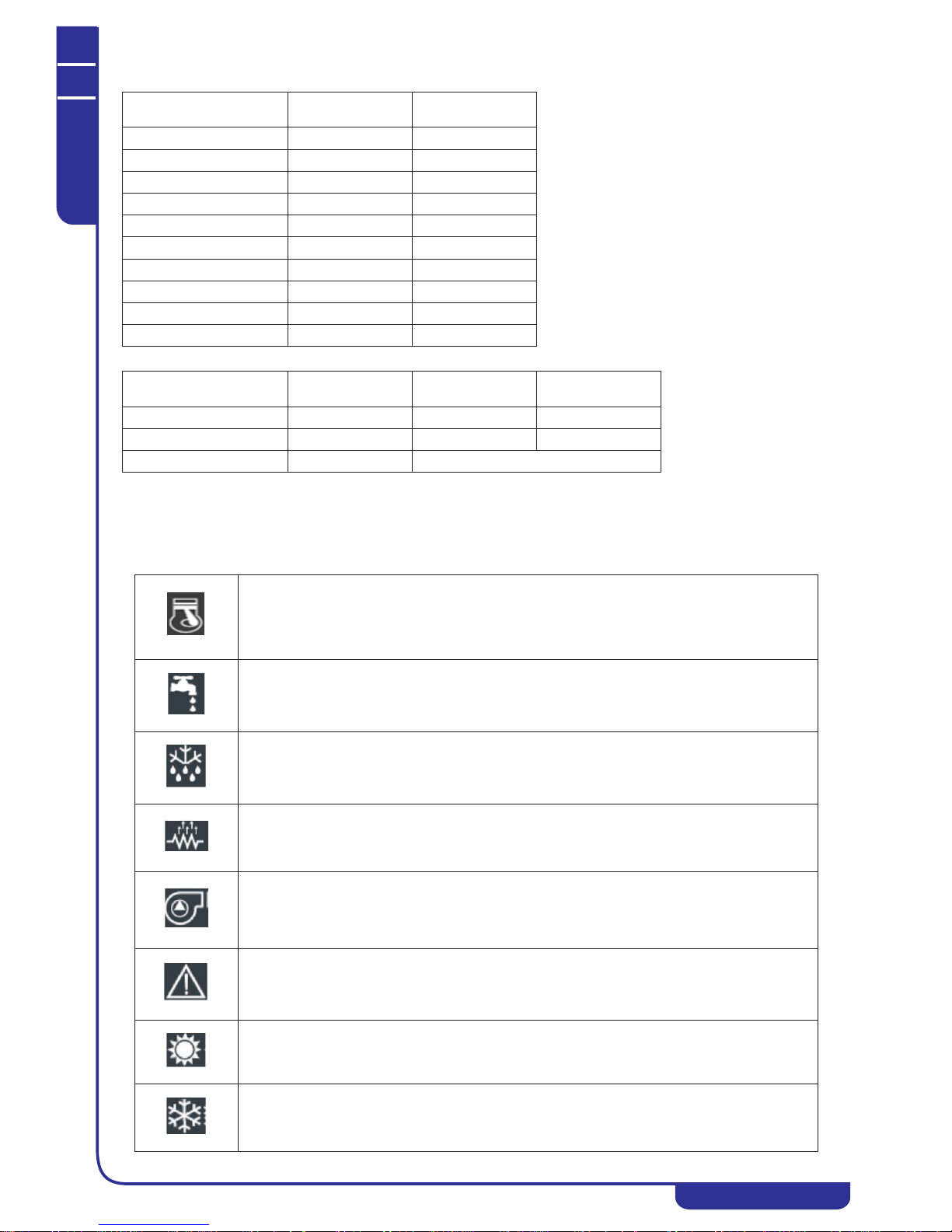
4.3 Safety signs
The unit carries the following safety signs, with which personnel must comply:
4.4 Refrigerants safety datasheet
Mask and goggles: A mask to protect the airways and protective goggles must be worn during cleaning operations.
General hazard.
Dangerous voltage.
Moving parts.
Surfaces which may cause injuries.
Denomination: R410A (50% Difluoromethane (R32); 50% Pentafluoroethane (R125).
INDICATION OF HAZARDS
Major hazards: Suffocation.
Specific hazards: Rapid evaporation can cause cold burns.
FIRST AID MEASURES
General information: Do not attempt to administer liquids or solids to persons who have lost consciousness.
Inhalation: Move victims to the open air.
Use oxygen or artificial respiration if necessary.
Do not administer adrenaline or similar substances.
Contact with the eyes: Wash thoroughly with plenty of clean water for at least 15 minutes and seek medical assistance.
Contact with the skin: Wash immediately in plenty of clean water.
Remove contaminated clothing immediately.
FIRE-FIGHTING MEASURES
Means of extinction: Any.
Specific hazards: Pressure rise.
Specific methods: Cool containers with water spray.
MEASURES IN THE EVENT OF ACCIDENTAL LEAKAGE
Individual precautions: Evacuate personnel to safe muster points.
Provide adequate ventilation.
Use personal protective equipment.
Environmental precautions: Evaporates.
Cleaning methods: Evaporates.
HANDLING AND STORAGE
Handling technical
measures/precautions:
Ensure the presence of sufficient ventilation and/or air extraction means in the workplace.
Recommendations for safe use: Do not breath fumes or aerosol.
Storage: Close hermetically and store in a cool, dry and well-ventilated place.
Store in its original containers. Incompatible products: explosive materials, inflammable materials,
organic peroxide.
CONTROL OF EXPOSURE/INDIVIDUAL PROTECTION
Control parameters: AEL (8-h and 12-h TWA) = 1000 ml/m3 for each of the two components.
Respiratory protection: For rescue and maintenance work in tanks, use autonomous breathing apparatus.
The vapours are heavier than air and can cause suffocation, reducing the oxygen available for breathing.
Protection of the eyes: Safety spectacles.
Protection of the hands: Rubber gloves.
Hygiene measures: Do not smoke.

TECHNICAL MANUAL
Chapter 5 - Technical features
NGSi 05÷15
7
ENGLISH
EN
The data in this manual are not binding and they can be modified by the manufacturer without notice. Reproduction of this manual is strictly prohibited
CHAPTER 5
TECHNICAL FEATURES
NGSi series water chillers and heat pumps are designed for residential and commercial applications. They are extremely versatile and when
operating in heat pump mode they are able to produce hot water at a temperature of 55°C for environmental heating and domestic use. The
brushless INVERTER compressor, combined with an electronic expansion valve, pump and variable speed fan, optimises the power
consumption and operating efficiency of the refrigerating components.
5.1 Frame
All NGSi units are in hot-galvanised sheet metal, painted with polyurethane powder enamels baked at 180°C to ensure the best resistance to
atmospheric agents. The frame is free-standing with removable panels for easier inspection and maintenance of the internal components. All
screws and rivets for outdoor installations are in galvanised steel.
5.2 Refrigerant circuit
The refrigerant circuit has been manufactured with components supplied by top international producers and in accordance with the UNI EN
13134 standard on braze-welding procedures. The refrigerant gas used is R410A. The refrigerant circuit includes: 4-way reverse cycle valve,
electronic expansion valve, liquid separator (07, 10 and 15 models), liquid receiver, inspection valves for maintenance and checks, PED
standard safety device (high pressure pressure switch), pressure transducers for accurate control of evaporating and condensing pressures and
filters to prevent fouling of the thermal expansion valve.
5.3 Compressors
The DC inverter compressors are of rotary hermetic (05 and 07 models), twin rotary (10 model) and scroll (15 model) types, specifically
designed for use with R410A refrigerant; they are all equipped with thermal overload protection and mounted on rubber dampers.
The compressors are installed in a separate chamber, out of the air stream, to reduce noise.
The crankcase heater is powered up when the compressor is off by at least 30 minutes and if the discharge temperature is below 20°C (with
hysteresis of 2.0°C). The crankcase heater is disabled when the compressor restarts. It is recommend to plug the unit in and put it on standby at least 6 hours before it starts operation.
Compressors can be inspected through the front panel, which allows maintenance to be performed even with the unit in operation.
5.4 Air side exchanger
The air side heat exchangers are constructed with copper tubes and aluminium fins. The copper tubes have a diameter of 7 mm in the 05 and
07 models and 5/16” in the 10 and 15 models; the aluminium fins are 0.1 mm thick. The tubes are mechanically expanded into the aluminium
fins to improve the heat exchange factor. The geometry of these exchangers guarantees low air side pressure drop, meaning that fans
operating at low rpm can be used (reducing the unit’s noise level).
5.5 Fans
The unit is fitted with plastic axial fans with aerofoil blades. They are all statically and dynamically balanced and supplied complete with
safety grille as required by the EN 60335 standard (safety of household and similar electrical appliances). The fans are installed on the unit
on rubber dampers to reduce the noise level. All electric motors used are of 8 pole modulating brushless type (200/1000 rpm). The motors are
directly coupled and equipped with integral thermal overload protection. Motors all have IP X4 protection rating.
5.6 User heat exchangers
The user heat exchangers are of braze-welded plate type and are in AISI 316 stainless steel, insulated with closed-cell material in the factory;
they can be equipped with antifreeze heaters (AK optional accessory). Each evaporator is protected by an antifreeze protection temperature
probe, which starts up the water circulator, even with the unit switched off, if the conditions set on the control unit occur.
PHYSICAL AND CHEMICAL PROPERTIES
Colour: Colourless.
Odour: Slight.
Boiling point: -52.8°C at atmospheric pressure.
Flash point: Non-flammable.
Relative density: 1.08 kg/l at 25°C.
Solubility in water: Negligible.
STABILITY AND REACTIVITY
Stability: No reactivity if used in compliance with the relative instructions.
Materials to avoid: Strong oxidants. Incompatible with magnesium, zinc, sodium, potassium and aluminium.
The incompatibility becomes more serious if the metal is in powder form or if the surfaces have recently
not been protected.
Hazardous decomposition
products:
These products are halogen compounds, hydrofluoric acid, carbon oxides (CO, CO2) and carbonyl
halides.
TOXICOLOGICAL INFORMATION
Acute toxicity: (R32) LC50/inhalation/4 hours/lab.rats >760 mg/l
(R125) LC50/inhalation/4 hours/lab.rats >3480 mg/l
Local effects: Concentrations significantly above the TLV can cause narcotic effects.
Inhalation of products in decomposition can lead to respiratory difficulty (pulmonary oedema).
Long-term toxicity: No carcinogenic, teratogenic, or mutagenic effects observed in laboratory animals.
ECOLOGICAL INFORMATION
Global warming potential GWP
(R11=1):
1.730
Ozone depletion potential ODP
(R11=1):
0
Considerations on disposal: usable with reconditioning.

TECHNICAL MANUAL
Chapter 6 - Versions available
NGSi 05÷15
8
ENGLISH
EN
The data in this manual are not binding and they can be modified by the manufacturer without notice. Reproduction of this manual is strictly prohibited
5.7 Control panel
The control panel is constructed in compliance with the relevant European standards. The panel is accessed by removing the front and side
panels and top of the unit with the aid of a suitable tool. The panel control protection rating is IP24. The panel also comprises a terminal
board with clean contacts for remote ON-OFF switching, summer/winter switching, the auxiliary heater, the domestic hot water sensor,
control of a remote 3-way valve and contacts for the remote control panel and double set point operation.
5.8 Control system
All NGSi units are equipped with a microprocessor with overheating control by means of the electronic thermostatic valve operated in
response to the signals sent by the pressure transducers. The CPU also controls the water temperature setting, antifreeze protection,
compressor timing, alarm reset, alarm control and operating LEDs. On request, the microprocessors can be connected to BMS remote control
systems and the simpler HNS system with our terminals. The control system, combined with the use of INVERTERS and the on-board
sensors, monitors performance of the inverter compressor, circulator and fan (2 fans in 10 and 15 models) and adapts its constantly and
swiftly as required.
The INVERTER system reduces the system’s minimum water content from the conventional 12-15 litres/kW of chilling power to the
ABSOLUTE figures of 18 litres for the 05, 25 litres for the 07, 35 litres for the 10 and 45 litres for the 15 model in the NGSi series.
Thanks to these exceptionally low water contents, NGSI series units are suitable for systems without water tanks, with obvious
benefits in terms of reduction in unit size, installation space requirements, heat loss and system installation and maintenance costs.
5.9 Monitoring and protection devices
All units are supplied as standard with the following monitoring and protection devices: return water temperature probe on the system water
return line,
operating and antifreeze probe on the pipe delivering water to the system, high pressure transducer, low pressure
transducer, compressor inlet and outlet temperature probes, compressor thermal protection devices, fan thermal protection devices, water
side flow switch to protect the evaporator and high pressure switch.
5.10 Water circuit
NGSi chiller units have an integral water circuit including the circulator pump, suitable for the use of chilled water and directly controlled by
the unit’s own control unit. The circulator, always of modulating type, has an induction motor. The water circuit also includes the expansion
vessel, the safety valve (6 bar) and the automatic air bleeder valve.
5.11 Fan speed regulation
The fan speed is controlled by the microprocessor in order to optimise the evaporation/condensation pressure for summer/winter operation,
to enable the unit to operate correctly.
CHAPTER 6
VERSIONS AVAILABLE
NGSi - reversible heat pump with integrated hydronic system (expansion vessel, safety valve, pressure gauge, modulating circulator pump,
flow switch, automatic air bleeder valve. intake/discharge valve).
Models available: 05, 07, 10 and 15.
6.1 Optional accessories
Hi-T - Multi-function touch screen remote control that integrates the centralized management of the minichiller and of the HNS system, the
functions of USB port, humidity and temperature sensors. It is also equipped with an extremely intuitive interface that simplifies the use of
the control.
CRH - Remote control panel for installation in the room for remote control of the unit, with extra functions in addition to those provided on
the unit, also able to control our hydronic terminals.
AG - Rubber dampers for installation underneath the unit to cushion any vibrations.
AK - Antifreeze kit (this accessory must be installed in the factory and must be specified when ordering). It comprises a heating cable wound
around the base of the unit near to the condensation coil and a Mylar heating element on the faces of the plate heat exchanger.
KDS - Double setpoint kit (already integrated in the Hi-T) for the management of a second working setpoint on the system side.
CHAPTER 7
INSTALLATION
7.1 General
When installing or servicing the unit, staff must comply strictly with the instructions provided in this manual and those on the unit itself, and
always take all necessary precautions. Failure to follow instructions may be dangerous.
MTA must be notified of the damage within 8 days. The Customer must draw up a written report in the event of significant damage.
WARNING:
The INVERTER control system is able to manage minimum system water contents of 18 litres for the 05 model, 25 litres for
the 07 model, 35 litres for the 10 model and 45 litres for the 15 model. These figures in litres are absolute values, and not values
per kW of rated power.
WARNING:
All the operations described below must only be performed by QUALIFIED STAFF. Before doing any work on the unit,
make sure that the electricity supply is disconnected.
On receipt of the unit, inspect it for damage: it left the factory in perfect condition. Any damage must be reported to the
forwarder at once and noted on the Delivery Sheet before it is signed.
TECHNICAL MANUAL
Chapter 7 - Installation
NGSi 05÷15
9
ENGLISH
EN
The data in this manual are not binding and they can be modified by the manufacturer without notice. Reproduction of this manual is strictly prohibited
7.2 Lifting and handling
7.3 Positioning and spaces required for technical purposes
* Recommended installation and maintenance space
** Recommended servicing and maintenance space
7.4 Water connections
The water connections must be made in accordance with national or local regulations; the pipelines may be in steel, galvanised steel or PVC.
The size of the pipelines must be carefully calculated for the unit’s rated flow rate and the pressure drops in the water circuit. All water
connections must be insulated with closed cell material of suitable thickness. The chiller must be connected to the pipeline by means of
flexible couplings. The following components should be installed in the water circuit:
• Well thermometer for measuring the temperature in the circuit.
• Manual gate valves for shutting off the chiller from the water circuit.
• Y-shaped metal filter (on the system return line) with metal mesh of no more than 1 mm.
• Loading assembly and discharge valve where necessary.
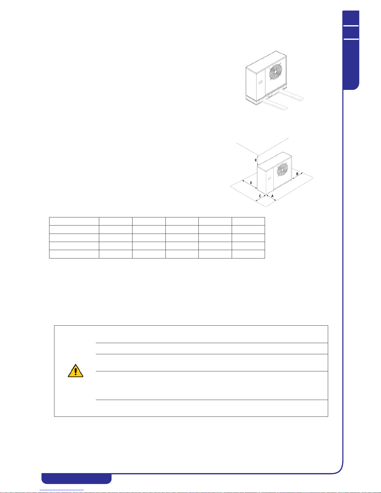
When unloading and positioning the unit, the greatest care must be taken to
avoid sharp or violent movements, to protect the internal components. Units can
be lifted with the aid of a forklift truck, or with slings, taking care not to damage
the side and top panels. The unit must always be kept horizontal during these
operations.
All NGSi series models are designed and built for outdoor installation; they
should therefore never be covered with canopy roofs or placed close to trees or
walls to ensure that air is not recycled through them. A plinth of suitable size for
the unit should be provided. Units transmit only a low level of vibration to the
ground, but vibration damping supports should be placed between the base frame
and the supporting surface. It is also important to avoid problems of recirculation
of air between the intake and delivery sides to avoid impairment of the unit’s
performance or even a shut-down of normal operation. To ensure this, the
minimum operating spaces detailed below must be left.
MOD. A B* C D E**
NGSi 05 1,500 500 400 400 500
NGSi 07 1,500 500 400 400 500
NGSi 10 1,500 500 400 400 500
NGSi 15 1,500 500 400 400 500
WARNING:
when deciding pipeline sizes, take care not to exceed the maximum system side pressure drop shown in the technical data
table in Section
“Technical data” (see working head values).
WARNING:
Connect the pipes to the connections using always the double key system.
WARNING:
The system return pipeline must be connected to the point marked “WATER INTAKE”; otherwise, the evaporator might
freeze.
WARNING:
A metal filter with (mesh of no more than 1 mm) must be installed on the system return pipeline labelled “WATER
INTAKE”. If the flow switch is tampered with or modified, or if the metal mesh filter is not installed on the system, all
warranty cover is forfeited at once. The filter must be kept clean, so the user must check after installation that it is still clean,
and then inspect it regularly.
All units leave the factory complete with flow switch (mounted in the factory). If the flow switch is modified or removed, or if
the water filter is not fitted in the unit, the warranty will lose all validity. Refer to the wiring diagram provided with the unit
for connection of the flow switch.

TECHNICAL MANUAL
Chapter 7 - Installation
NGSi 05÷15
10
ENGLISH
EN
The data in this manual are not binding and they can be modified by the manufacturer without notice. Reproduction of this manual is strictly prohibited
7.4.1 Connecting to the condensate drain
All NGSi units are built so that the base of the unit acts as a condensate collection basin. A plastic union is supplied as standard for
connection to the fitting provided underneath the base, to allow connection of a pipe to drain off the condensate.
The base of the hydronic kit of each unit (on the right-hand side panels) of each unit also has a hole to allow drainage of any condensate
which may percolate from the water system pipes. Since these pipes are well insulated, the amount of condensate produced is minimal, and
therefore the connection of a drain pipe to this hole is not essential.
7.4.2 Service tap
If it becomes necessary to top up the system or adapt the glycol concentration, it is possible to use the service valve. Unscrew the cap of the
service tap and connect a hose connection to the 14 mm (inner diameter) hose connected to the water network, and then load the system by
unscrewing the ring nut. After the operation, re-tighten the nut and screw on the cap. It is in any case recommendable for loading the system,
to use an external tap whose prearrangement is made by the installer.
7.4.3 System drainage
If it is necessary to fully discharge the unit, first close the inlet and outlet manual gate valves (not supplied) and then remove the tubes
arranged externally on the water inlet and outlet so as to drain the liquid contained in the unit (to make this operation easy, it is
recommended to externally install on the water input and output two drain valves interposed between the unit and the manual gate valves).
7.4.4 Water system diagram
Condensate drain union Union connected to the unit Condensate drain union fitting
KEY
A Plate heat exchanger
B Flow switch
CService tap
D Circulator pump
E Expansion vessel
F Air bleed valve
G Safety valve
H Pressure gauge
Ring nut
Cap with gasket
A
B
H
G
F
E
D
C

TECHNICAL MANUAL
Chapter 7 - Installation
NGSi 05÷15
11
ENGLISH
EN
The data in this manual are not binding and they can be modified by the manufacturer without notice. Reproduction of this manual is strictly prohibited
7.5 5-9 kW chiller diagram
7.6 12-15 kW chiller diagram
C Compressor
CLS Compressor liquid separator
ST Compressor intake temperature
DT Compressor outlet temperature
HP High pressure transducer
Pr High pressure switch
LP Low pressure transducer
LS Liquid separator (on 07, 10 and 15 models only)
4WV Cycle reverser valve
LR Liquid receiver
EEV Electronic expansion valve
FL Filter
M Axial fan
SE External air temperature
P Circulator installed on unit
IN Water intake temperature
OUT Water outlet temperature
C Compressor
CLS Compressor liquid separator
OS Oil separator (on 10 and 15 models only)
ST Compressor intake temperature
DT Compressor outlet temperature
HP High pressure transducer
Pr High pressure switch
LP Low pressure transducer
LS Liquid separator (on 07, 10 and 15 models only)
4WV Cycle reverser valve
LR Liquid receiver
EEV Electronic expansion valve
NRV Check valve (may be fitted on some models)
FL Filter
M Axial fan
SE External air temperature
P Circulator installed on unit
IN Water intake temperature
OUT Water outlet temperature
CP Capillary
WARNING:
The unit must be installed in a manner which allows maintenance and repairs. The warranty does not cover costs of the
platforms or handling equipment required for any work on the unit.
All maintenance and inspection procedures must only be performed by QUALIFIED STAFF.
Before doing any work on the unit, make sure that the electricity supply is disconnected.
WARNING:
The unit contains several moving components. Take great care when working in their vicinity, even if the electricity supply is
disconnected.
The compressor heads and delivery pipeline are often at quite high temperatures. Take special care when working in the
vicinity of the heat exchanger coils.
The aluminium fans are particularly sharp and may cause serious injuries.
SE
EEV
LR
IN
OUT
4WV
DT
LP
HP
ST
M
P
C
LS
OS
FL FL
NRV
CP
CLS
Pr

TECHNICAL MANUAL
Chapter 7 - Installation
NGSi 05÷15
12
ENGLISH
EN
The data in this manual are not binding and they can be modified by the manufacturer without notice. Reproduction of this manual is strictly prohibited
7.7 Electrical connections
Check that the electricity supply corresponds to the unit’s rated data (voltage, phases and frequency) marked on the nameplate on its righthand panel. The electrical connection must be made in accordance with the wiring diagram supplied with the unit and with the local and
international regulations (provide a magneto-thermal master switch, differential security breakers for each line, suitable ground connection
for the system, etc.). The power supply cables, electrical protection devices and line fuses must be of the size stated in the unit’s wiring
diagram and in the electrical data in the technical specification table (see Section
“Technical data”).
7.7.1 Connection terminal board
The electrical connections must be made by qualified staff. The connection terminal board underneath the plastic cover on the same side
as the water connections (for the 10 and 15 models, the protective casing must be removed). When connecting the terminal board, comply
with the instructions provided below (the drawing is guideline).
The connections described below are standard. Other connections are described in the table in Point 9.25.
After maintenance procedures, put the panels back in place, securing them with the fixing screws.
WARNING:
There must be no variations in the power supply voltage in excess of ±10% of the nominal value. If this tolerance is not
complied with, please contact our technical department.
WARNING:
The electricity supply must comply with the stated limits: otherwise, the warranty becomes null and void immediately. Before
starting any work on the unit, make sure that the electricity supply is disconnected.
WARNING:
The flow switch (B in the water system diagram above and installed in the factory) must ALWAYS be connected as stated in
the wiring diagram. Never bridge the flow switch connections on the terminal board. No warranty cover will be provided if
the flow switch connections have been modified or incorrectly connected.
WARNING:
The remote control panel is connected to the chiller by 4 cables with gauge 1.5 mm
2
. The power supply cables must be
separate from the remote control cables. Maximum distance 50 metres.
WARNING:
The remote control panel cannot be installed in an area with strong vibrations, corrosive gases, excess dirt or high humidity
levels. Leave the area close to the cooling system unobstructed.
The connections to the terminal board must only be made by qualified staff.
Terminal Type Connection
GND power supply
1-Ph/N/PE
230V, 50Hz
(3-Ph/N/PE
400 Vac, 50Hz in the 15kW size)
connect the ground cable
N1 power supply
1-Ph/N/PE
230V, 50Hz
(3-Ph/N/PE
400 Vac, 50Hz in the 15kW size)
connect the mains neutral cable
L1 power supply
1-Ph/N/PE
230V, 50Hz
(3-Ph/N/PE
400 Vac, 50Hz in the 15kW size)
connect the mains live cable (in three-phase versions, there
are two additional terminals, L2 and L3).

TECHNICAL MANUAL
Chapter 7 - Installation
NGSi 05÷15
13
ENGLISH
EN
The data in this manual are not binding and they can be modified by the manufacturer without notice. Reproduction of this manual is strictly prohibited
NC1 digital output
230 Vac with exchange contact
NC terminal for supply of power (230V AC) to 3-way valve
for domestic hot water heater (only used for 3-way valves
with 3-point power supply, for switching to system side)
(for other configurations see Point 9.25)
N digital output
230 Vac with exchange contact
neutral terminal for supply of power (230V AC) to 3-way
valve for domestic hot water heater (for other
configurations see Point 9.25)
NO1 digital output
230 Vac with exchange contact
NO terminal for supply of power (230V AC) to 3-way valve
for domestic hot water heater (for switching the valve to the
heater side) (for other configurations see Paragraph 9.25)
NC2 digital output
230 Vac with exchange contact
NC terminal for supply of power (230V, 50Hz, 5A resistive
load, 1 A inductive load) to 3-way valve for double setpoint
for radiators (optional to be used only on series V2, see
Point
“Double setpoint kit (optional accessory)”) (for
other configurations see Point 9.25)
N2 digital output
230 Vac with exchange contact
neutral terminal for supply of power (230V AC) to 3-way
valve for double setpoint for radiators (optional to be used
only on series V2, see Point
“Double setpoint kit (optional
accessory)”
) (for other configurations see Point 9.25)
NO2 digital output
230 Vac with exchange contact
NO terminal for supply of power (230V, 50Hz, 5A resistive
load, 1 A inductive load) to 3-way valve for double setpoint
for radiators (optional to be used only on series V2, see
Point
“Double setpoint kit (optional accessory)”) (for
other configurations see Point 9.25)
R+ serial communication connection of modbus + signal for remote keypad
R-
serial communication connection of modbus - signal for remote keypad
GNDR serial communication modbus for remote keypad ground reference connection
12V+ power supply output 12Vac, 50Hz remote keypad power supply output (12V, 50Hz, 500mA)
12V- power supply output 12Vac, 50Hz remote keypad power supply output (12V, 50Hz, 500mA)
SE analogue (ST8) / digital (DI7) input input for humidity switch for double setpoint control
(optional) (for other configurations see Point 9.25)
SE analogue (ST8) / digital (DI7) input input for humidity switch for double setpoint control
(optional) (for other configurations see Point 9.25)
AEHN digital output (DO3) 230Vac neutral output for backup heater for domestic hot water
(230V, 50Hz, 5A) (for other configurations see Point 9.25)
AEH digital output (DO3) 230 Vac phase output for backup heater for domestic hot water
(230V, 50Hz, 5A) (per for other configurations see Point
9.25)
SAN analogue input (ST9) / digital (DI8) input for domestic hot water heater probe (for other
configurations see Point 9.25)
SAN analogue input (ST9) / digital (DI8) input for domestic hot water heater probe (for other
configurations see Point 9.25)
DO5N digital output (DO5) 230 Vac neutral output (optional to be used only if the machine has
not the antifreeze kit “AK” included) (for other possible
configurations see Point 9.25)
DO5 digital output (DO5) 230 Vac phase output (optional to be used only if the machine has
not the antifreeze kit “AK” included) (for other possible
configurations see Point 9.25)
DO4N digital output (DO4) 230 Vac neutral output (230V, 50Hz, 5A resistive load,
1 A inductive load) (optional to be used only if the machine
has not the antifreeze kit “AK” included) (for other possible
configurations see Point 9.25)
DO4 digital output (DO4) 230 Vac phase output (230V, 50Hz, 5A resistive load, 1 A inductive
load) (optional to be used only if the machine has not the
antifreeze kit “AK” included) (for other possible
configurations see Point 9.25)
SW digital input input for remote summer/winter mode switching (closed=
summer mode / open= winter mode)
SW digital input input for remote summer/winter mode switching (closed=
summer mode / open= winter mode)
onoff digital input remote on/off input (closed=unit on / open=unit off)
Terminal Type Connection

TECHNICAL MANUAL
Chapter 8 - Start-up
NGSi 05÷15
14
ENGLISH
EN
The data in this manual are not binding and they can be modified by the manufacturer without notice. Reproduction of this manual is strictly prohibited
CHAPTER 8
START-UP
Before start-up:
• Check that system diagrams and manuals for the unit installed are available.
• Check that electrical and water system diagrams of the system to which the unit is connected are available.
• Check that the water circuit stop taps are turned on.
• Check that the water system has been filled and pressurised and the air has been vented.
• Check that all the water system connections have been made correctly and all the instructions on the decals have been
followed.
• Check that arrangements have been made for the drainage of condensate.
• Check the electrical connection and that all the terminals are secure.
• Check that the electrical connections have been made in accordance with the relevant standards, including the ground
connection.
• The voltage must be as stated on the unit nameplate.
• Check that the power supply voltage is within the tolerance limits (±10%).
• Check that the compressor heaters are receiving power correctly.
• Check that there are no gas leaks.
• Before switching on the system, check that all the enclosing panels are in place and secured with the screws provided.
CHAPTER 9
USER - CONTROL INTERFACE
onoff digital input remote on/off input (closed=unit on / open=unit off)
0-10V+ analogue input (ST10) 0-10V (+) signal input for setpoint modification
0-10V- analogue input (ST10) 0-10V (-) signal input for setpoint modification
WARNING:
The unit must be connected to the electrical mains and set in STANDBY mode (powered up) by turning on the master switch
at least 12 hours before start-up, to allow the heater to warm up the compressor crankcase as required (the heaters are
automatically powered up when the master switch is on). The heaters are operating correctly if the compressor crankcase
temperature has risen to 10÷15°C above room temperature within a few minutes.
WARNING:
Never stop the unit temporarily by turning off the master switch; this must only be done to disconnect the unit from the power
supply for lengthy stoppages (e.g. seasonal lay-offs, etc.). When the power supply is disconnected the crankcase heaters no
longer receive power, leading to the risk of a compressor breakdown when the unit is started up.
WARNING:
Do not modify the electrical connections to the unit; otherwise, warranty cover is forfeited at once.
WARNING:
Summer/winter operating mode must be selected at the start of the relative season. Frequent switching back and forth
between these modes is not recommended, as it may damage the compressors.
WARNING:
When the unit is installed and commissioned, check that it operates correct in both heating and cooling modes.
Selects the operating mode and resets alarms which can be rearmed manually. The sequence at consecutive
pressures on the key is:
off Æ cool ÆheatÆ off
If domestic hot water is enabled, the sequence is:
offÆ cool Æ cool+san Æ heat Æheat+sanÆ off
During parameter setting, it moves BACK one level.
Accesses the parameter setting menu, allowing setting of the summer, winter and domestic hot water setpoints.
Terminal Type Connection

TECHNICAL MANUAL
Chapter 9 - User - Control Interface
NGSi 05÷15
15
ENGLISH
EN
The data in this manual are not binding and they can be modified by the manufacturer without notice. Reproduction of this manual is strictly prohibited
9.1 Menu structure
Level 0 (U) = always visible
Level 1 (M) = visible if the maintenance password (H80) or the manufacturer password is entered
Level 2 (C) = visible only if the manufacturer password is entered
Level 3 (A)= visible only through Modbus
9.1.1 Analogue inputs menu
Entering the maintenance password in the analogue inputs menu “tP” at level 1 of the menu structure of the control installed on the unit, it is
possible to read the values of the probes:
t01: water intake temperature (°C);
t02: water outlet temperature (°C);
t03: compressor intake temperature (°C);
t04: compressor outlet temperature (°C);
t05: high pressure (bar);
t06: low pressure (bar);
t07: outdoor air temperature (°C);
t09: domestic hot water temperature (°C) (if domestic hot water production is enabled).
UP key. In parameter setting mode, used to move to a higher level menu or to increase the value of a parameter
when in “modify” mode.
DOWN key. In parameter setting mode, used to move to a lower level menu or to decrease the value of a
parameter when in “modify” mode.
Level 0 Level 1 Level 2 Level 3 Level 4
Adjustment probe
Acve alarm
U Setpoint:
SEt
Label Set cooling:
Coo
Cooling setpoint value
Label Set heang:
HEA
Heang setpoint value
M
Analogue Input:tP
Input code:
t01-t04
Analogue Input value
UAlarms:
Err
Acve alarms code:
E00
M
Digital Inputs: Id Input code:
i01-i05
Digital input status
M Parameters:
PAr
Parameters category
Parameter index Parameter value
U Password:
PSS
Password value
M
Operaon Hours:
Ohr
Compressor hours 1:
OH1
Number of hours
Compressor hours 2:
OH2
Number of hours
Pump hours:
OHP
Number of hours
U = user
M = maintainer
C = manufacturer
TECHNICAL MANUAL
Chapter 9 - User - Control Interface
NGSi 05÷15
16
ENGLISH
EN
The data in this manual are not binding and they can be modified by the manufacturer without notice. Reproduction of this manual is strictly prohibited
9.2 Parameters category
9.3 Setpoints settable by the user
The second setpoint is only operational if the relative optional kit has been purchased.
9.4 Display
Normally, the display shows the water output temperature in tenths of a degree Celsius or the alarm code if at least one alarm has been
tripped. With several alarms present, the first one is shown and the second one appears after the first has been reset. In menu mode, the
contents of the screen depend on the function being used.
9.5 LEDs
Description
Group identification
code
Parameter index
Configuration
CnF H01-
Compressor
CP C01-
Fan
FAn F01-
Alarms
ALL A01-
Adjustment
Re b01-
Pump
PUP P01-
Electric heaters
Fro r01-
Defrosting
dFr d01-
Electronic valve
EEu U01-
Offset
OFF o01-
Setpoint type
Setpoint
(summer/winter)
Summer
default (range)
Winter
default (range)
First setpoint [°C]
Coo/Hea 7 (5÷18) 45 (35÷55)
Second setpoint [°C]
Co2/He2 18 (7÷23) 35 (25÷45)
Hot water setpoint [°C]
San 48 (25÷55)
Compressor LED • ON with compressor in operation.
• OFF with compressor not running.
• FLASHING if compressor start delay timer is running.
Domestic hot
water LED
• ON with domestic hot water valve active.
• OFF with domestic hot water valve not active.
Defrost LED • ON with defrosting active.
• OFF with defrosting disabled or completed.
• FLASHING if defrosting interval timer is running.
Antifreeze heater
LED
• LED ON with antifreeze heater (optional) in operation.
Pump LED • LED ON with pump in operation.
Alarm LED • LED ON with an alarm tripped.
Heating mode
LED
• LED ON with unit in heating mode.
Cooling mode
LED
• LED ON with unit in cooling mode.

TECHNICAL MANUAL
Chapter 9 - User - Control Interface
NGSi 05÷15
17
ENGLISH
EN
The data in this manual are not binding and they can be modified by the manufacturer without notice. Reproduction of this manual is strictly prohibited
9.6 Modifying the dynamic setpoint
The regulator allows the setpoint to be modified by adding an offset to the external air temperature probe reading. To use this function, the
user has to set the values of parameters b08 to b14 following the instructions provided below (modifications to be made by the installer).
Parameters of regulator PAr->rE->
• b08 = dynamic setpoint enabled=1 / disabled=0 (must be disabled if weather compensation from the optional CRH remote
keypad is used).
• b09 = cooling maximum offset.
• b10 = heating maximum offset.
• b11 = External temperature setting in cooling mode.
• b12 = External temperature setting in heating mode.
• b13 = Temperature delta in cooling mode.
• b14 = Temperature delta. in heating mode.
Modifying the setpoint in relation to the external temperature:
9.7 Modifying the setpoint from 0-10V input
Another type of adjustment allows to change the set-point by adding (or subtracting) a value according to the 0-10V input (if enabled). To
enable the function, set H21=40, and if necessary change the value of the parameter b15 (0-10 range), taking into consideration that:
• with 0 Volt input the current setpoint will be: (Coo/Hea) setpoint set – b15/2
• with 5 Volt input the setpoint will be the one set (Coo/Hea)
• with 10 Volt input the current setpoint will be: (Coo/Hea) setpoint set – b15/2
Cooling
Heating
Ext. temp. set.
Ext. temp. set.

TECHNICAL MANUAL
Chapter 9 - User - Control Interface
NGSi 05÷15
18
ENGLISH
EN
The data in this manual are not binding and they can be modified by the manufacturer without notice. Reproduction of this manual is strictly prohibited
The 0-10V signal must be applied to 0-10V+ and 0-10V terminals (see wiring diagrams).
NOTE
In “cool” mode, considering that the chiller setpoint by default is set to 7°C, the parameter b15 must not have a value greater than or equal
to 6 to ensure that the new setpoint set from the 0-10V input can achieve values below the antifreeze activation threshold (4°C).
9.8 Hydraulic pump operation
The hydraulic pump can be set according to one of the three following types of operation:
• operation on call of the temperature controller (default)
• operation on call from the temperature controller with periodic activation
• continuous operation
The pump is switched off immediately if the flow switch alarm is activated in manual reset.
The pump instead is always on if the antifreeze heaters are operating or if the hydraulic pump in antifreeze mode operation is activated.
The operation in antifreeze mode is activated if the adjustment temperature drops below P04 °C (default 5°C), it is disabled if the adjustment
temperature rises above P04+P05 °C (Default value of P05=2.0°C).
The pump adjustment is proportional (see Point 9.8.4).
9.8.1 Operation on call from temperature controller (Default)
In this user mode (P03=1, default), the pump is activated upon request of the temperature controller; and after a time delay of 20 seconds
from the pump start up, also the compressor activates. In power off, instead, the pump is switched off with a delay time of 120 seconds from
the call with the temperature controller in off status (off status coinciding with the compressor power off).
With flow switch alarm active in automatic reset the pump is however turned on even if the compressor is off.
If the machine operation is enabled from the remote “on-off” digital input (see Point 9.10), the circulator is immediately activated for a time
of 2 minutes, regardless of the temperature control inside the unit (the activated water recirculation allows the correct activation of the
temperature control).
0 - 10 V Input [V]
New setpoint [°C]
Setpoint set

TECHNICAL MANUAL
Chapter 9 - User - Control Interface
NGSi 05÷15
19
ENGLISH
EN
The data in this manual are not binding and they can be modified by the manufacturer without notice. Reproduction of this manual is strictly prohibited
9.8.2 Operation on call from temperature controller with periodic activation
The function is disabled if P17=0 (default). If the pump is set into operation on call from the temperature controller (P03=1, default), it is
activated periodically for a time defined by the parameter P17 (in seconds) after a count whose duration can be set by the parameter P16 (in
minutes), activated when the pump is switched off when the temperature control is met.
With flow switch alarm active in automatic reset the pump is however turned on even if the compressor is off.
The periodic function is also interrupted in the case of intervention of the antifreeze regulator that forces the pump activation.
9.8.3 Continuous operation
In this operation mode, which is active if P03=0, the pump is always on. It is powered off only with the unit OFF.
9.8.4 Pump proportional adjustment
The pump speed is varied according to the temperature difference between the exchanger intake water and discharge water, according to the
diagram below, where:
P07: modulating pump maximum speed (%)
P08: modulating pump minimum speed (%)
P09: modulating pump intake/discharge water Delta T set (°C)
P10: Modulating pump Delta (°C)
Temperature controller
Compressor
Pump
Time
Time
Time
Power on delay between
pump and compressor
Power off delay between
compressor and pump

TECHNICAL MANUAL
Chapter 9 - User - Control Interface
NGSi 05÷15
20
ENGLISH
EN
The data in this manual are not binding and they can be modified by the manufacturer without notice. Reproduction of this manual is strictly prohibited
In domestic hot water production the pump is forced to the maximum speed.
9.9 Heaters for antifreeze protection (if AK accessory is installed)
The antifreeze heaters on the faces of the evaporator plates come on even with the unit off (but powered up) when the output water
temperature drops below r02 °C (default 4°C) in “heat” mode or below r03 °C (default 4°C) in “cool” and “OFF” mode. The heaters are
switched off when the temperature reading of the output water probe exceeds r02+r06 in “heat” or r03+r06 in “cool” mode and in “OFF”
(default value r06=2.0°C). The heating cable on the base of the machine is activated, instead, when the outside air temperature drops below
3°C or the machine goes into defrost (after a set delay). It is disabled when the outdoor temperature exceeds 5°C.
9.10 Remote on-off and remote summer-winter switching
The terminal board has two digital inputs for operating the unit by means of a remote enabling signal.
9.11 Remote water temperature probe
In some system solutions (e.g. heat pump in parallel with the hot water tank on the same hydronic circuit and bypass diverter valve) it may
be necessary to remotely control the system temperature probe so that the controller installed on the unit can successfully process the system
management.
To configure the remote probe set H19=41 and H44=0 and connect the probe to the SE-SE terminals, or set H20=41 and H45=0 to use the
SAN-SAN terminals).
9.12 Domestic hot water production enable
To activate the domestic hot water function, connect a probe to be inserted in the tank to the SAN-SAN terminals (enabled as analogue
input). After fitting and connecting the temperature probe, the domestic hot water function has to be enabled by setting parameter H10 with
the value 1 and parameter H20 with the value 6 to enable the analogue input for the probe. These settings are accessed by entering the
maintenance password and accessing parameters PRG->PSS->PAr->Cnf->H10/H20 (modifications to be made by the installer).
If the domestic hot water temperature is below the relative setpoint (set at 48°C by default, which can be modified by accessing the PRG-
>Set->SAN menu) the unit activates the domestic hot water valve and the compressor switches to the minimum frequency for a time of 2
minutes, giving the valve time to divert the flow of water to the domestic hot water tank. After the switching time, the compressor is set at
the maximum frequency starting the modulation at one degree before the setpoint and switching off one degree after. Once the setpoint is
reached, the valve returns to the rest position and compressor operation is controlled in the usual way.
If a 3-way switching valve with 3-point power supply is used, it must be connected to terminals NO1, N and NC1.
If a 3-way switching valve with 2-point power supply (with return spring) is used, it must be connected to terminals NO1 and N.
Contact NO1 closed means that the valve is excited and is diverting the flow of water to the domestic hot water tank.
Contact NO1 open means that the valve is not excited and is diverting the flow of water to the user.
SW-SW:
Input for remote summer/winter mode switching.
To enable this function, set parameter H76 with the value 1.
The parameter is protected by a password (it can only be modified by the installer).
With open contact the machine is in “heat” mode, with closed contact the machine switches to “cool” mode.
onoff-onoff:
Remote on-off input.
This function is already enabled by default.
Remove the jumper from the terminal board to set the unit in standby status (in this status the display of control
installed on the unit shows “E00”).
When the contact closes, the machine comes out of the standby mode and the circulator is turned on for 2 minutes.
If the domestic hot water operation is enabled, the remote on-off function has no effect on the production of ACS,
it disables only the operation in heating and chiller mode on the system side (in this status the display installed on
the unit shows “SAN”).

TECHNICAL MANUAL
Chapter 9 - User - Control Interface
NGSi 05÷15
21
ENGLISH
EN
The data in this manual are not binding and they can be modified by the manufacturer without notice. Reproduction of this manual is strictly prohibited
When the system switches from user water to domestic hot water, the working probe changes its function from “water outlet probe” to
“domestic hot water probe”. When the system switches from winter to domestic hot water operation, the compressor does not switch off and is
turned up to the maximum frequency set by the controller, while if it switches from summer to domestic hot water, the compressor is switched
off and waits for the safety pause time.
9.12.1 Probe storage in heating mode
When the system switches from user water to domestic hot water, the working probe changes its function from “water outlet probe” to
“domestic hot water probe”. For this reason, in hot mode, before entering into domestic hot water mode, the last value read by the probe is
stored.
After the domestic hot water temperature control is met, the reference temperature on the system side returns to the temperature previously
stored. The storage function stops:
• in the moment in which the temperature read by the probe becomes lower than the stored value;
• or after the expiry of a time equal to b06 seconds (default 45 seconds).
9.12.2 Domestic hot water production call from digital input
Alternatively to the temperature probe use, the activation of the domestic hot water function can be performed by closing a digital input of
the unit (SAN SAN terminals enabled as digital input). This function is recommended in case of use of two or more minichillers hydronically
connected in cascade to a same storage tank for domestic hot water; in this way the domestic hot water tank function is imposed by the tank
probe connected to the first machine, while the other machines are enabled automatically by digital consent. Only in machines with domestic
hot water call from digital input, in addition to enabling the domestic hot water function with H10=1, it is also necessary to enable the
digital input setting H20=0, H45=28, H54=128. For each minichiller (except the last of the cascade), it is necessary to use a relay (not
supplied), controlled by the output 230VAC NO1 and N present in the terminal board, which enables, through its COM and NO clean
contacts, the SAN SAN digital input of the chiller in the next cascade. For this configuration, refer to the wiring diagram below.

TECHNICAL MANUAL
Chapter 9 - User - Control Interface
NGSi 05÷15
22
ENGLISH
EN
The data in this manual are not binding and they can be modified by the manufacturer without notice. Reproduction of this manual is strictly prohibited
NOTE
If the unit is switched off from a remote control position (by means of the onoff-onoff terminals), the keypad on the unit or a remote keypad,
operation in domestic hot water mode is unaffected. Once parameter H10 has been set as 1, the unit switches to domestic hot water mode as
priority as soon as it is powered up. The display on the unit shows the temperature reading of the probe inside the domestic hot water tank.
Once the domestic hot water cycle has been completed, the display again shows the water output probe temperature.
If the remote ON-OFF digital input (onoff onoff terminals) is open, with domestic hot water function enabled (H10=1 and H20=6), the
machine display instead shows “SAN”. Once the sanitary cycle is finished, the display returns to show the message “E00” indicating that the
remote ON-OFF contact is open.
During winter mode operation, defrosting always takes place on the user side and never on the domestic hot water tank.
9.13 Domestic hot water accumulation in hot mode
If the parameter H83=1, the machine utilizes the domestic hot water accumulation tank also for heating on the system side. In these
conditions, the relay that controls the domestic hot water valve is energized also during operation in hot mode and not only in domestic hot
water mode. During defrosting and in chiller mode the valve is de-energized. When H83=1 it is possible to enable the domestic hot water
Terminal board
of the
Terminal board
of the
Settings
H10=1
H20=6
Settings
H10=1
H20=0
H45=28
H54=128
SAN, SAN direction
of the terminal board
of the Minichiller
no. 3
Towards L1, N1, GND
of the terminal board
of the Minichiller
no. 3
Rated voltage
of the
230 V AC coil
COM, NO
Clean contact
for domestic hot
water call from the
digital input
Rated voltage
of the
230 V AC coil
COM, NO
Clean contact
for domestic hot
water call from the
digital input
3-way valve
side
Domestic hot water sensor
Domestic hot water tank side
Connection for valve with 3-point power supply only, system side
no. 1
no. 2
Minichiller
Minichiller

TECHNICAL MANUAL
Chapter 9 - User - Control Interface
NGSi 05÷15
23
ENGLISH
EN
The data in this manual are not binding and they can be modified by the manufacturer without notice. Reproduction of this manual is strictly prohibited
backup heater to that is acts also as a backup heater on system side: for this purpose set r10=1 and r15=2 (for other settings of r15 refer to
Point 9.16); furthermore no digital output must be set as the system backup heater.
9.14 System backup heaters
The system backup heater output is active only with the settings H58=22 (output 230V AEH AEHN already set by default) or H61=22
(output 230V NO1 N, not set by default) (for other outputs which can be used in the terminal board and the related settings refer to Point
9.25). The heater is enabled using parameter r10=1. It is also necessary to set the parameter r24 to 1 or to 3 (refer to the r24 parameter
settings explanation in Point 9.18). In heat pump normal operation mode, if the control temperature remains lower than the water setpoint
less r11 (°C) and the machine is in cut-out mode for the intervention of an alarm, the heater is enabled. It turns off when the machine comes
out of the cutout alarm. The backup heater can also be activated with the heat pump not in cut-off mode, depending on the machine operation
in the joint ranges or in replacement mode indicated in Point 9.18, if the production of hot water continues for a time longer than the
operation time set with the parameter r12 (minutes), always if the control temperature remains below the water setpoint minus r11 (°C). In
these cases, the heater is switched off when the machine reaches the setpoint set (also taking into account any offset set with parameters r29
or r30 (refer to Point 9.18).
9.15 Systems backup heater in defrost mode
During the defrost cycle (see Point 9.21), setting r21=1 (in addition to r10=1 and r24=1 or 3) the electric heater activates on the system side,
if required (control temperature below the water setpoint minus r11 (°C)), without waiting for the time defined by r12.
9.16 Domestic hot water backup heater
This is an additional resources for heating the water in the domestic hot water tank if the compressor alone is not able to reach the setpoint
within a reasonable time. The domestic hot water backup heater output is only active with the settings H58=26 (output 230V, AEH, AEHN
not set by default) or H61=26 (output 230V NO1 N not set by default) (for other outputs that can be used in the terminal board and their
configurations refer to Point 9.25).
The heater is enabled with the parameter r15=1 (with r15=0 the heater is disabled). It is also necessary to set the parameter r24 to 2 or to 3
(refer to the r24 parameter settings explanation in Point 9.18). If the production of domestic hot water continues for a time longer than r16
(minutes) or if the machine enters in cutout mode for the intervention of an alarm, the heater is activated. It turns off when the machine
finishes the production of domestic hot water (taking into account a possible offset of the setpoint set with the parameter r31, as explained in
Point 9.18).
9.17 Backup heaters selection mode
It is possible to set the backup heaters activation priority order on the system side and domestic hot water side, in particular the
configurations are:
1. r14=0 (default), the heaters can be activated simultaneously if present;
2. r14=1, the heaters are activated in exclusion to each other:
• r20=0, system priority (the domestic hot water heater is activated only if the temperature control is reached for the system
side heater);
• r20=1, domestic hot water priority (the system side heater is activated only if the temperature control is reached for the
domestic hot water side heater).
9.18 Activation of backup and hot water tank heaters in joint operation
mode/compressor replacement mode
The compressor use is inhibited in case of low outside temperature.
Considering this mode, there are 4 areas of operation of the machine:
1. operation in heat pump mode (normal operation, with the compressor enabled) in which the backup heaters and the hot water
tank intervene only in case the heat pump goes into alarm;
2. joint operation (First range), in which the compressor use is enabled in synergy with the auxiliary heaters (in winter or
domestic hot water modes, if the outdoor temperature drops below r22 (°C) (default 7°C) but remains above r28 (default -7°C).
The operation returns normal if the temperature rises above r22+1.0 (°C). In particular, in this range of operation, the auxiliary
heaters and the hot water tank are activated after a time defined by r12 (minutes) for the system side and by r16 (minutes) for
the domestic hot water side, from the activation of the heat pump, according to the priorities set by the parameters r14, r20
(refer to Point 9.17) and r23, r24 (see following explanation). If the backup heaters are used, they must be enabled also from the
parameter r10 (system backup heater case, see Point 9.14) and from the parameter r15 (domestic hot water backup heater case,
see Point 9.16).
3. joint operation (Second range), in which the compressor use is enabled in synergy with the auxiliary heaters (in winter or
domestic hot water modes, if the outdoor temperature drops below r28 (°C) (default -7°C) but remains above r08 °C (default 16°C). The operation returns normal if the temperature rises above r28+1.0 (°C). In particular, in this range of operation, the hot
water tank is activated first, then the heat pump and the auxiliary heaters after a time defined by r12 (minutes) for the system
side and by r16 (minutes) for the domestic hot water side, according to the operating priorities set by the parameters r14, r20
(refer to Point 9.17) and r23, r24. If the backup heaters are used, they must be enabled also from the parameter r10 (system
backup heater case, see Point 9.14) and from the parameter r15 (domestic hot water backup heater case, see Point 9.16).
If the system or domestic hot water backup heater must start after the heat pump, it is necessary to enable the hot water tank
setting r23 with one of the values among 4, 5 or 6, instead if the system heater has to start before the heat pump r23 must be
configured with 0, 1, 2 or 3 (therefore even when the hot water tank is not used).
4. operation in replacement mode, in which the compressor use is inhibited and the auxiliary units operate in their replacement
according to the times defined with r12 (minutes) for the system side and r16 (minutes) for the domestic hot water side, (in winter or
domestic hot water mode, if the outdoor temperature drops below r08
(°C), default -16°C). The compressor is enabled again if the
temperature rises above r08+ r09 (°C) (r09=1.0°C by default).
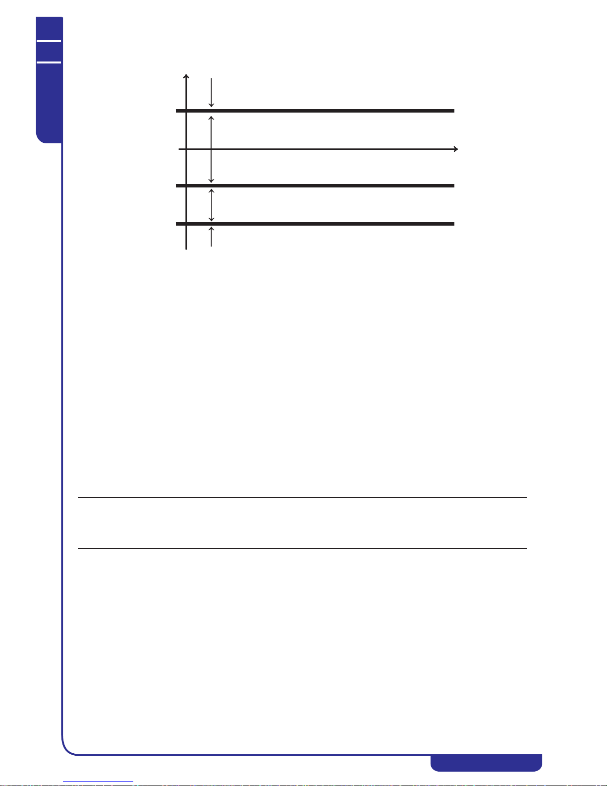
TECHNICAL MANUAL
Chapter 9 - User - Control Interface
NGSi 05÷15
24
ENGLISH
EN
The data in this manual are not binding and they can be modified by the manufacturer without notice. Reproduction of this manual is strictly prohibited
If it is necessary to change the value of parametersr22, r28, r08, comply with r22 r28 r08.
Setting r22=r28 it is possible to eliminate the zone related to the joint operation of the First range; setting r28=r08 it is possible to eliminate
the zone related to the joint operation of the Second range; setting r22=r28=r08 it is possible to eliminate both ranges related to the joint
operation.
The auxiliary units which can be used for the joint operation or for operation in replacement mode are:
• hot water tank (or external heaters with independent temperature control), installed if H58=29 (output 230V AEH AEHN
not set by default) or H61=29 (output 230V NO1 N, not set by default); (for other outputs that can be used in the terminal
board and their configurations refer to Point 9.25).
• system backup heater (refer to Point 9.14);
• domestic hot water heater (refer to Point 9.16).
For the allowed configurations and the digital outputs that can be used in the terminal board refer to Point 9.25 and electricaldiagrams.
To define the mode of use the auxiliary units, it is necessary to set the parameter r23, which defines how to use the hot water tank, and the
parameter r24,which defines how to use the backup heaters:
• r23=0 hot water tank not used (heaters intervention priority);
• r23=1 hot water tank used only on system (heaters intervention priority);
• r23=2 hot water tank used only in domestic hot water mode (heaters intervention priority);
• r23=3 hot water tank used both in domestic hot water mode and on system (heaters intervention priority);
• r23=4 hot water tank used only on system with priority (no heaters intervention priority);
• r23=5 hot water tank used only in domestic hot water mode with priority (no heaters intervention priority);
• r23=6 (default) hot water tank used both in domestic hot water mode and on system with priority (no heaters intervention
priority);
• r24=0 backup heaters not used;
• r24=1 only system backup heater use;
• r24=2 only domestic hot water backup heater use
• r24=3 use of both system backup heater and domestic hot water backup heater.
NOTE
In the first three ranges (heat pump operation, First Range joint operation and Second Range joint operation), to enable the system backup
heaters, also r10=1 must be set, while to enable the domestic hot water backup heater also r15=1 must be set. In the replacement mode
operation range, however, it is not necessary to enable the backup heaters with r10 or r15 since the heaters operate in replacement mode
(and not in backup mode) to the heat pump (therefore it is necessary to just select the type of use by parameter r24).
It is then possible to configure an analogue input in the minichiller for a possible remotable probe for detecting the system water temperature
(set H19=41 and H44=0 to connect the remotable probe to the SE-SE terminals, or H20=41 and H45=0 to use the SAN-SAN terminals) (See
Point 9.11).
The possible configurations of the backup parameters are listed in Tables 1,2,3 and 4 shown below, divided by operation ranges (in the
“STATUS” boxes and by “rxx” parameters; the mode of operation and possible parameters values are shown so that a given order of
intervention of the backup units occurs in a given operation of the machine; more parameters statuses and values can be selected
alternatively and are therefore shown within a same cell separated by the symbol “/”).
Pompa di calore
T
est
.[°C]
r22=7
r28=-7
r08=-16
0
Pompa di calore + [ Caldaia e/o Resistenza]
FUNZIONAMENTO CONGIUNTO I FASCIA
Caldaia e/o Resistenza
Caldaia + [ Pompa di calore e/o Resistenza]
FUNZIONAMENTO CONGIUNTO II FASCIA
Heat pump
Heat pump+ [Hot water tank and/or Heater]
JOINT OPERATION FIRST RANGE
Hot water tank + [Heat pump and/or Heater]
JOINT OPERATION SECOND RANGE
Hot water tank and/or Heater
OPERATION IN REPLACEMENT MODE

TECHNICAL MANUAL
Chapter 9 - User - Control Interface
NGSi 05÷15
25
ENGLISH
EN
The data in this manual are not binding and they can be modified by the manufacturer without notice. Reproduction of this manual is strictly prohibited
Table 1 HEAT PUMP NORMAL OPERATION
No.
BACKUP
OPERATIONS ORDER
(A set-point not met and
with the machine in
cutout alarm)
STATUS OPERATION r10 r15 r12 r16 r23 r24
1
1) System backup
heater
HEAT /
HEAT+
DOMESTIC
HOT WATER
heat 1 0/1/2 / / 0/2/5 1/3
2
1) Hot water tank
HEAT /
HEAT+
DOMESTIC
HOT WATER
heat 0/1 0/1/2 / / 1/3/4/6 0/2
3
1) System backup
heater
2) After r12 minutes, hot
water tank
HEAT /
HEAT+
DOMESTIC
HOT WATER
heat 1 0/1/2 set the
minutes
/1/31/3
4
1) Hot water tank
2) After r12 minutes,
system backup heater
HEAT /
HEAT+
DOMESTIC
HOT WATER
heat 1 0/1/2 set the
minutes
/4/61/3
5
1) Domestic hot water
backup heater
HEAT+
DOMESTIC
HOT WATER
domestic hot
water
0/1 1 / / 0/1/4 2/3
6
1) Hot water tank
HEAT+SAN/
COOL+SAN
domestic hot
water
0/1 0/1/2 / / 2/3/5/6 0/1
7
1) Domestic hot water
backup heater
2) After r15 minutes, hot
water tank
HEAT+
DOMESTIC
HOT WATER
domestic hot
water
0/1 1 / set the
minutes
2/3 2/3
8
1) Hot water tank
2) After r15 minutes,
domestic hot water
backup heater
HEAT+
DOMESTIC
HOT WATER
domestic hot
water
0/1 1 / set the
minutes
5/6 2/3
9
1) System/domestic hot
water backup heater
HEAT /
HEAT+
DOMESTIC
HOT WATER
both in heat
mode and
domestic hot
water mode
11 / / 03
10
1) Hot water tank
HEAT /
HEAT+
DOMESTIC
HOT WATER
both in heat
mode and
domestic hot
water mode
0/1 0/1/2 / / 3/6 0
11
1) System/domestic hot
water backup heater
2) After r12 minutes, hot
water tank
HEAT /
HEAT+
DOMESTIC
HOT WATER
both in heat
mode and
domestic hot
water mode
11set the
minutes
set the
minutes
33
12
1) Hot water tank
2) After r12 minutes,
system/domestic hot
water backup heater
HEAT /
HEAT+
DOMESTIC
HOT WATER
both in heat
mode and
domestic hot
water mode
11set the
minutes
set the
minutes
63
Table 2 JOINT OPERATION, RANGE 1
No.
OPERATION ORDER
(A set-point not met)
STATUS OPERATION r10 r15 r12 r16 r23 r24
1
1) Heat pump
2) After r12 minutes,
system backup heater
HEAT /
HEAT+
DOMESTIC
HOT WATER
heat 1 0/1/2 set the
minutes
/ 0/2/5 1/3

TECHNICAL MANUAL
Chapter 9 - User - Control Interface
NGSi 05÷15
26
ENGLISH
EN
The data in this manual are not binding and they can be modified by the manufacturer without notice. Reproduction of this manual is strictly prohibited
2
1) Heat pump
2) After r12 minutes, hot
water tank
HEAT /
HEAT+
DOMESTIC
HOT WATER
heat 0/1 0/1/2 set the
minutes
/ 1/3/4/6 0/2
3
1) Heat pump
2) After r12 minutes,
system backup heater
3) After additional r12
minutes, hot water tank
HEAT /
HEAT+
DOMESTIC
HOT WATER
heat 1 0/1/2 set the
minutes
/1/31/3
4
1) Heat pump
2) After r12 minutes, hot
water tank
3) After additional r12
minutes, system backup
heater
HEAT /
HEAT+
DOMESTIC
HOT WATER
heat 1 0/1/2 set the
minutes
/4/61/3
5
1) Heat pump
2) After r15 minutes,
domestic hot water
backup heater
HEAT+
DOMESTIC
HOT WATER
domestic hot
water
0/1 1 / set the
minutes
0/1/4 2/3
6
1) Heat pump
2) After r15 minutes, hot
water tank
HEAT+
DOMESITC
HOT WATER/
domestic hot
water
0/1 0/1/2 / set the
minutes
2/3/5/6 0/1
7
1) Heat pump
2) After r15 minutes,
domestic hot water
backup heater
3) After additional r15
minutes, hot water tank
HEAT+
DOMESTIC
HOT WATER
domestic hot
water
0/1 1 / set the
minutes
2/3 2/3
8
1) Heat pump
2) After r15 minutes, hot
water tank
3) After additional r15
minutes, domestic hot
water backup heater
HEAT+
DOMESTIC
HOT WATER
domestic hot
water
0/1 1 / set the
minutes
5/6 2/3
9
1) Heat pump
2) After r12 minutes,
system/domestic hot
water backup heater
HEAT /
HEAT+
DOMESTIC
HOT WATER
both in heat
mode and
domestic hot
water mode
1 1 set the
minutes
set the
minutes
03
10
1) Heat pump
2) After r12 minutes, hot
water tank
HEAT /
HEAT+
DOMESTIC
HOT WATER
both in heat
mode and
domestic hot
water mode
0/1 0/1/2 set the
minutes
set the
minutes
3/6 0
11
1) Heat pump
2) After r12 minutes,
system/domestic hot
water backup heater
3) After additional r12
minutes, hot water tank
HEAT /
HEAT+
DOMESTIC
HOT WATER
both in heat
mode and
domestic hot
water mode
1 1 set the
minutes
set the
minutes
33
12
1) Heat pump
2) After r12 minutes, hot
water tank
3) After additional r12
minutes,
system/domestic hot
water backup heater
HEAT /
HEAT+
DOMESTIC
HOT WATER
both in heat
mode and
domestic hot
water mode
1 1 set the
minutes
set the
minutes
63
Table 2 JOINT OPERATION, RANGE 1
No.
OPERATION ORDER
(A set-point not met)
STATUS OPERATION r10 r15 r12 r16 r23 r24

TECHNICAL MANUAL
Chapter 9 - User - Control Interface
NGSi 05÷15
27
ENGLISH
EN
The data in this manual are not binding and they can be modified by the manufacturer without notice. Reproduction of this manual is strictly prohibited
Table 3 JOINT OPERATION, RANGE 2
No.
OPERATION ORDER
(A set-point not met)
STATUS OPERATION r10 r15 r12 r16 r23 r24
1
1) Hot water tank
2) After r12 minutes,
heat pump
HEAT /
HEAT+
DOMESTIC
HOT WATER
heat 0/1 0/1/2 set the
minutes
/ 1/3/4/6 0/2
2
1) Hot water tank
2) After r12 minutes,
system backup heater
3) After additional r12
minutes, heat pump
HEAT /
HEAT+
DOMESTIC
HOT WATER
heat 1 0/1/2 set the
minutes
/1/31/3
3
1) Hot water tank
2) After r12 minutes,
heat pump
3) After additional r12
minutes, system backup
heater
HEAT /
HEAT+
DOMESTIC
HOT WATER
heat 1 0/1/2 set the
minutes
/4/61/3
4
1) System backup
heater
2) After r12 minutes,
heat pump
HEAT /
HEAT+
DOMESTIC
HOT WATER
heat 1 0/1/2 set the
minutes
/0/2/51/3
5
1) Hot water tank
2) After additional r15
minutes, heat pump
HEAT+
DOMESTIC
HOT WATER
domestic hot
water
0/1 0/1/2 / set the
minutes
2/3/5/6 0/1
6
1) Hot water tank
2) After r15 minutes,
domestic hot water
backup heater
3) After additional r15
minutes, heat pump
HEAT+
DOMESTIC
HOT WATER
domestic hot
water
0/1 1 / set the
minutes
2/3 2/3
7
1) Hot water tank
2) After r15 minutes,
heat pump
3) After additional r15
minutes, domestic hot
water backup heater
HEAT+
DOMESTIC
HOT WATER
domestic hot
water
0/1 1 / set the
minutes
5/6 2/3
8
1) Domestic hot water
backup heater
2) After r15 minutes,
heat pump
HEAT+
DOMESITC
HOT WATER/
domestic hot
water
0/1 1 / set the
minutes
0/1/4 2/3
9
1) Hot water tank
2) After r12 minutes,
heat pump
HEAT /
HEAT+
DOMESTIC
HOT WATER
both in heat
mode and
domestic hot
water mode
1 1 set the
minutes
set the
minutes
3/6 0
10
1) Hot water tank
2) After r12 minutes,
system/domestic hot
water backup heater
3) After additional r12
minutes, heat pump
HEAT /
HEAT+
DOMESTIC
HOT WATER
both in heat
mode and
domestic hot
water mode
1 1 set the
minutes
set the
minutes
33
11
1) Hot water tank
2) After r12 minutes,
heat pump
3) After additional r12
minutes,
system/domestic hot
water backup heater
HEAT /
HEAT+
DOMESTIC
HOT WATER
both in heat
mode and
domestic hot
water mode
1 1 set the
minutes
set the
minutes
63
12
1) System/domestic hot
water backup heater
2) After r12 minutes,
heat pump
HEAT /
HEAT+
DOMESTIC
HOT WATER
both in heat
mode and
domestic hot
water mode
1 1 set the
minutes
set the
minutes
03

TECHNICAL MANUAL
Chapter 9 - User - Control Interface
NGSi 05÷15
28
ENGLISH
EN
The data in this manual are not binding and they can be modified by the manufacturer without notice. Reproduction of this manual is strictly prohibited
Table 4 REPLACEMENT OPERATION
No.
OPERATION ORDER
(A set-point not met)
STATUS OPERATION r10 r15 r12 r16 r23 r24
1
1) Hot water tank
2) After r12 minutes,
System backup heater
HEAT /
HEAT+
DOMESTIC
HOT WATER
heat 0/1 0/1/2 set the
minutes
/4/61/3
2
1) System backup
heater
2) After r12 minutes, hot
water tank
HEAT /
HEAT+
DOMESTIC
HOT WATER
heat 0/1 0/1/2 set the
minutes
/1/31/3
3
1) Hot water tank
2) After r12 minutes,
Domestic hot water
backup heater
HEAT+
DOMESTIC
HOT WATER
domestic hot
water
0/1 0/1/2 / set the
minutes
5/6 2/3
4
1) Domestic hot water
backup heater
2) After r12 minutes, hot
water tank
HEAT+
DOMESTIC
HOT WATER
domestic hot
water
0/1 0/1/2 / set the
minutes
2/3 2/3
5
1) Hot water tank
2) After r12 minutes,
System/domestic hot
water backup heater
HEAT /
HEAT+
DOMESTIC
HOT WATER
both in heat
mode and
domestic hot
water mode
0/1 0/1/2 set the
minutes
set the
minutes
63
6
1) System/domestic hot
water backup heater
2) After r12 minutes, hot
water tank
HEAT /
HEAT+
DOMESTIC
HOT WATER
both in heat
mode and
domestic hot
water mode
0/1 0/1/2 set the
minutes
set the
minutes
33
7
1) Hot water tank
HEAT /
HEAT+
DOMESTIC
HOT WATER
heat 0/1 0/1/2 set the
minutes
/ 1/3/4/6 0/2
8
1) System backup
heater
HEAT /
HEAT+
DOMESTIC
HOT WATER
heat 0/1 0/1/2 set the
minutes
/ 0/2/5 1/3
9
1) Hot water tank
HEAT+
DOMESTIC
HOT WATER
domestic hot
water
0/1 0/1/2 / set the
minutes
2/3/5/6 0/1
10
1) Domestic hot water
backup heater
HEAT+
DOMESTIC
HOT WATER
domestic hot
water
0/1 0/1/2 / set the
minutes
0/1/4 2/3
11
1)Hot water tank
HEAT /
HEAT+
DOMESTIC
HOT WATER
both in heat
mode and
domestic hot
water mode
0/1 0/1/2 set the
minutes
set the
minutes
3/6 0
12
1) System/domestic hot
water backup heater
HEAT /
HEAT+
DOMESTIC
HOT WATER
both in heat
mode and
domestic hot
water mode
0/1 0/1/2 set the
minutes
set the
minutes
03

TECHNICAL MANUAL
Chapter 9 - User - Control Interface
NGSi 05÷15
29
ENGLISH
EN
The data in this manual are not binding and they can be modified by the manufacturer without notice. Reproduction of this manual is strictly prohibited
Table 5 shows the settings required to enable the backup units in “Summer and domestic hot water” mode (in this case, the only backup that
can be activated is the domestic hot water backup heater and the division into operating ranges does not apply).
Table 6 shows the behaviour of the system and domestic hot water backup heaters in all operation cases of the machine.
It can finally be established that the hot water tank and/or backup heaters (depending on the resources and the priorities selected) have a
setpoint in “heat” mode or in “domestic hot water” mode greater than that of the heat pump. This is achieved by setting an offset on the
setpoints:
• r29: Temperature offset for hot water tank and system heaters first setpoint (G02);
• r30: Temperature offset for hot water tank and system heaters first setpoint (G05);
• r31: Temperature offset for hot water tank and domestic hot water heaters (G03).
Table 5 OPERATION IN COOL + DOMESTIC HOT WATER MODE (DOMESTIC HOT WATER IN OPERATION)
No.
BACKUP
OPERATIONS ORDER
- A setpoint not met after
r16 minutes after the
compressor start or
- a setpoint not met with
machine in cutout alarm
STATUS OPERATION r10 r15 r12 r16 r23 r24
1
1) Domestic hot water
backup heater
COOL+
DOMESTIC
HOT WATER
domestic hot
water
0/1 1 / set the
minutes
0/1/2/
3/4/5/6
2/3
Table 6 BACKUP HEATERS OPERATION
No. STATUS OPERATION SYSTEM BACKUP HEATER
DOMESTIC HOT WATER
BACKUP HEATER
1
HEAT+DOMESTIC HOT
WATER
heat It works as shown in Tables
1,2,3 and 4.
In “HEAT + DOMESTIC HOT
WATER” mode the domestic
hot water temperature control
by default has precedence over
the system, so if the
temperature control requires it,
the machine goes into
“DOMESTIC HOT WATER”
operation and the domestic hot
water backup heater works as
shown in Tables 1, 2, 3 and 4.
2
HEAT+DOMESTIC HOT
WATER
domestic hot water Only if all of the following 3
conditions occurred:
- configured the output for
System backup Heater;
- r24=1/3;
- water temperature remote
probe of the current system
and configured
(see Point 9.11).
The system backup heater start
operating in the following
situations:
- after r12 minutes after the
counting starts in “HEAT”
mode which was previously in
operation (see line No. 1);
- if the counting in the
“HEAT” operation mode
mentioned above has not
already been activated, after
r12 minutes from the request
of temperature control.
In DOMESTIC HOT WATER
mode, with remote probe not
configured, the system backup
heater is disabled or its counts
are interrupted.
With “remote on-off” contact
open the System backup heater
is disabled.
It works as shown in Tables
1,2,3 and 4.
3
COOL+ DOMESTIC HOT
WATER
domestic hot water It can not be activated. It operates as shown in table 5.
4
COOL+ DOMESTIC HOT
WATER
cool It can not be activated. It can not be activated.

TECHNICAL MANUAL
Chapter 9 - User - Control Interface
NGSi 05÷15
30
ENGLISH
EN
The data in this manual are not binding and they can be modified by the manufacturer without notice. Reproduction of this manual is strictly prohibited
In this way, the heat pump will stop at the setpoint set (G02, G03, G05) and the temperature difference, according to the offset set, will be
supported by the hot water tank and/or the heaters.
9.19 System season indication
It is possible to configure a digital output to indicate the season of operation of the machine, on system side (the digital outputs are 230V
AC, for this purpose they must therefore operate a relay not supplied with voltage-free contacts). The digital outputs are configured setting
to 31 the parameters H58 (230V AEH, AEHN output) or H61 (230V, NO1, N output) (for other outputs which can be used in the terminal
board and their configurations see Part 9.25). The output is active in summer operation, while in OFF or heat status it is disabled. During
domestic hot water operation, the output keeps the same setting of the season of origin.
9.20 Fan and dissipation control
The dissipation control depends on the condensing pressure in chiller mode, while it depends on the evaporation pressure in heat pump
mode.
The ventilation adjustment occurs in a way dependent on the compressor operation.
9.20.1 Ventilation control in chiller mode
The ventilation control in chiller mode occurs according to the diagram shown below, where:
F08 = Pressure setpoint for the fan minimum speed in chiller mode
F09 = Fan proportional band in chiller mode
F10 = Fan delta cut-off in chiller/heating mode
F11 = Cut-off hysteresis in chiller/heating mode
F14 = Pressure setpoint for the fan maximum speed in chiller mode
In chiller mode a pre-ventilation period is active: before starting the compressor, the fan is turned on for 5 seconds; the fan speed is
proportional to the condensing temperature, however, if the controller requires the cut-off during this period, the fan will run at the minimum
speed set. This function prevents the compressor from starting with too high condensation temperatures.
9.20.2 Ventilation control in heating mode
The ventilation control in heat pump mode occurs according to the diagram shown below, where:
F17 = Pressure setpoint for fan minimum speed in heating mode
F18 = Fan proportional band in heating mode
F10 = Fan delta cut-off in chiller/heating mode
F11 = Cut-off hysteresis in chiller/heating mode
F20 = Pressure setpoint for fan maximum speed in heating mode

TECHNICAL MANUAL
Chapter 9 - User - Control Interface
NGSi 05÷15
31
ENGLISH
EN
The data in this manual are not binding and they can be modified by the manufacturer without notice. Reproduction of this manual is strictly prohibited
9.21 Defrost cycle
The defrost cycle is a function that works only in heat pump mode and is used to prevent the formation of ice on the surface of the air/air
battery. The formation of ice on the evaporator, which occurs more frequently for very low temperatures of the external environment, in
addition to greatly reducing the thermodynamic efficiency of the machine, leads to the risk of damaging the machine itself.
9.22 Compressor crankcase heater
The crankcase heater is activated when the compressor is off for at least 30 minutes and if the discharge temperature is below a certain
threshold (20°C with a hysteresis of 2.0°C). The crankcase heater is disabled when the compressor restarts.
9.23 Functions which can be enabled with Hi-T accessory
9.23.1 Screed function
A function is implemented in the machines for connecting the screed in radiator systems installation. This function can be activated only if
the Hi-T accessory is installed, therefore for more information, refer to the manual of this control.
9.23.2 Disinfection (Legionella prevention)
The legionella prevention disinfection function is implemented in the machines. This function is enabled only if the Hi-T accessory is
installed, therefore for more details refer to the manual of this control. The parameters related to disinfection are:
• r25: Disinfection setpoint (anti-legionella) (in °C);
• r26: Disinfection duration (in minutes);
• r27: Heat pump in disinfection mode operation setpoint (in °C).
9.24 Handbook for installation configurations
In case of need for clarification on the possible configurations, a “Handbook”has been prepared, which is a technical book consisting of a
collection of system diagrams which highlights some of the proposed installation configurations of our high efficiency heat pumps. The
“Handbook” also sets the task of showing the symbiosis potential with some of our items in the catalogue.
Ask the Head Office in order to consult the technical handbook.
9.25 Tables of settings which can be made by the user and installer
Parameter Description Unit Default Range Visibility Permitted settings Notes
Coo First cooling
setpoint
°C 7.0 5.0÷Co2 U
Hea First heating
setpoint
°C 45.0 He2÷55.0 U
San Domestic hot water
setpoint
°C 48.0 25.0...55.0 U
Co2 Second cooling
setpoint
°C 18.0 Coo÷23.0 U
He2 Second heating
setpoint
°C 35.0 25.0÷Hea U

TECHNICAL MANUAL
Chapter 9 - User - Control Interface
NGSi 05÷15
32
ENGLISH
EN
The data in this manual are not binding and they can be modified by the manufacturer without notice. Reproduction of this manual is strictly prohibited
H10 Domestic hot water
function enabling
/ 0 0...1 I
0 = function
disabled
1 = function
enabled
H19 ST8 input
configuration
/ 0 0...41 I
0 = input not
assigned
41= water
temperature remote
probe
SE-SE Terminals
Input which can be
used in exclusion
of D.I.7 (if used set
H44=0)
H20 ST9 input
configuration
/ 0 0...41 I
0 = input not
assigned
6 = domestic hot
water temperature
41= water
temperature remote
probe
SAN-SAN
terminals
Input which can be
used in exclusion
of D.I.8. (if used
set H45=0)
H21 ST10 configuration
/ 0 0...41 I
0 = input not
assigned
40= 0-10V input
0-10V-0-10V
Terminals
H44
DI7 Configuration
/ 26 0...28 I
0=input not
assigned
26= humidity
switch second
setpoint
28= domestic hot
water temperature
control from digital
mode
SE-SE Terminals
Input which can be
used in exclusion
of ST8 (if used set
H19=0)
H45 DI8 configuration
/ 0 0...28 I
0 = input not
assigned
26= humidity
switch second
setpoint
28= domestic hot
water temperature
control from digital
mode
SAN-SAN
terminals
Input which can be
used in exclusion
of ST9 (if used set
H20=0)
H54 Digital inputs
polarity
/ 0 0...255 I
0= digital inputs
polarity= NO
64 = polarity DI7 =
NC (for domestic
hot water
temperature
controller digital
call from SE-SE)
128= polarity
DI8=NC (for
domestic hot water
temperature
controller digital
call from SANSAN)
H58 DO3 configuration
/ 22 0...32 I
0 = input not
assigned
22= system backup
heater
24= alarm
26= domestic hot
water backup
heater
29= hot water tank
31= system season
indication
AEHN-AEH
terminals to
connect to the
remote control
switch coil (NO
230Vac contact)
Parameter Description Unit Default Range Visibility Permitted settings Notes

TECHNICAL MANUAL
Chapter 9 - User - Control Interface
NGSi 05÷15
33
ENGLISH
EN
The data in this manual are not binding and they can be modified by the manufacturer without notice. Reproduction of this manual is strictly prohibited
H59 DO4 configuration
/ 0 0...32 I/ Not
visible if
the
machine
is with
AK from
the
factory
0 = input not
assigned
22= system backup
heater
24= alarm
26= domestic hot
water backup
heater
29= hot water tank
31= system season
indication
DO4N-DO4
terminals
It is recommended
to use an external
relay to limit the
total power
consumption of the
machine
H60 DO5 configuration
/ 0 0...32 I/ Not
visible if
the
machine
is with
AK from
the
factory
0 = input not
assigned
22= system backup
heater
24= alarm
26= domestic hot
water backup
heater
29= hot water tank
31= system season
indication
DO5N-DO5
terminals
It is recommended
to use an external
relay to limit the
total power
consumption of the
machine
H61 Open collector 1
configuration
/ 6 0...32 I
0 = input not
assigned
6= domestic hot
water 3-way valve
22= system backup
heater
24= alarm
26= domestic hot
water backup
heater
29= hot water tank
31= system season
indication
For correct
connection to
terminals NC1,N1
and NO1 see Points
21.8.1 and 21.8.2.
It is necessary to
use an external
relay to limit the
total power
consumption of the
machine
.H62 Open collector 2
configuration
/ 25 0...32 I
0 = input not
assigned
22= system backup
heater
24= alarm
25= radiator 3-way
valve
26= domestic hot
water backup
heater
29= hot water tank
31= system season
indication
For correct
connection to
terminals NC2, N2
and NO2 see Points
21.8.1 and 21.8.2.
It is recommended
to use an external
relay to limit the
total power
consumption of the
machine.
H76 Remote operating
mode
(summer/winter)
selection
/ 0 0...1 I
0 = function
disabled
1 = function
enabled
H79 Serial address
/ 1 1...200 I
In case of more
minichillers in
cascade assign a
different address
to each control.
H82 Double setpoint
enabling
/ 0 0...4 I
0= selection menu
appears on CRH
1= standard mode
2= summer double
setpoint
3= winter double
setpoint
4= summer and
winter double
setpoint
Parameter Description Unit Default Range Visibility Permitted settings Notes

TECHNICAL MANUAL
Chapter 9 - User - Control Interface
NGSi 05÷15
34
ENGLISH
EN
The data in this manual are not binding and they can be modified by the manufacturer without notice. Reproduction of this manual is strictly prohibited
H83 Enabling of
constant heating of
domestic hot water
/ 0 0...1 I
0 = function
disabled
1= with heating
always turned to
domestic hot water
A16 Cooling low
pressure setting
Bar 5.0 4.0...80.0 I
If in doubt
concerning the
value to set,
contact the
manufacturer
Values other than
the default value
may impair
operation of
the unit.
b01 Band in chiller
mode
°C 1.0 0...10.0 I
If in doubt
concerning the
value to set,
contact the
manufacturer
Values other than
the default value
may impair
operation of
the unit.
b02 Band in heating
mode
°C 1.0 0...10.0 I
If in doubt
concerning the
value to set,
contact the
manufacturer
Values other than
the default value
may impair
operation of
the unit.
b03 Band in domestic
hot water mode
°C 1.0 0...10.0 I
If in doubt
concerning the
value to set,
contact the
manufacturer
Values other than
the default value
may impair
operation of
the unit.
b04 Radiator valve
switching time
seconds 30 0...600 I
b06 Transient domestic
hot water output
seconds 45 0...255 I
b08 Dynamic setpoint
enabling
/ 0 0...1 I
0 = function
disabled
1 = function
enabled
b09 Cooling maximum
offset
°C 3.0 -50.0...80.0 I
b10 Heating maximum
offset
°C -3.0 -50.0...80.0 I
b11 Cooling mode
external
temperature
setpoint
°C 25 -127...127 I
b12 Heating mode
external
temperature
setpoint
°C 15 -127...127 I
b13 Cooling mode
temperature delta
°C -10.0 -50.0...80.0 I
b14 Heating mode
temperature delta
°C 10.0 -50.0...80.0 I
b15 Decalibration band
setting from 0-10V
analogue input
°C 5.0 0.0...10.0 I
b20 0-10V
input/ratiometric
enable
/ 0 0...1 I
0= 0-10V input
1= ratiometric
input
F08 Pressure setting
with fan operation
at minimum speed
in chiller mode
Bar depending
on model
-50.0...80.0 I
If in doubt
concerning the
value to set,
contact the
manufacturer
Values other than
the default value
may impair
operation of
the unit.
F09 Proportional band
for fan modulation
in chiller mode
Bar depending
on model
0.0...25.5 I
If in doubt
concerning the
value to set,
contact the
manufacturer
Values other than
the default value
may impair
operation of
the unit.
Parameter Description Unit Default Range Visibility Permitted settings Notes

TECHNICAL MANUAL
Chapter 9 - User - Control Interface
NGSi 05÷15
35
ENGLISH
EN
The data in this manual are not binding and they can be modified by the manufacturer without notice. Reproduction of this manual is strictly prohibited
F10 Fan cut-off delta
Bar depending
on model
0.0...25.5 I
If in doubt
concerning the
value to set,
contact the
manufacturer
Values other than
the default value
may impair
operation of
the unit.
F11 Cut-off hysteresis
Bar depending
on model
0.0...25.5 I
If in doubt
concerning the
value to set,
contact the
manufacturer
Values other than
the default value
may impair
operation of
the unit.
F12 Cut-off bypass time
Sec depending
on model
0...25.5 I
If in doubt
concerning the
value to set,
contact the
manufacturer
Values other than
the default value
may impair
operation of
the unit.
F14 Pressure setpoint
with fan at
maximum speed in
chiller mode
Bar depending
on model
-50.0...80.0 I
If in doubt
concerning the
value to set,
contact the
manufacturer
Values other than
the default value
may impair
operation of
the unit.
F17 Pressure setting
with fan at
minimum speed in
hot mode
Bar depending
on model
-50.0...80.0 I
If in doubt
concerning the
value to set,
contact the
manufacturer
Values other than
the default value
may impair
operation of
the unit.
F18 Proportional band
for modulating the
fan in hot mode
Bar depending
on model
0.0...25.5 I
If in doubt
concerning the
value to set,
contact the
manufacturer
Values other than
the default value
may impair
operation of
the unit.
F20 Pressure setting
with fan at
maximum speed in
hot mode
Bar depending
on model
-50.0...80.0 I
If in doubt
concerning the
value to set,
contact the
manufacturer
Values other than
the default value
may impair
operation of
the unit.
P03 Pump operation
mode
/ 1 0...1 I
0= continuous
operation
1= operation
according to the
temperature control
P04 Antifreeze pump
setting
°C 5 -15...15 I
If in doubt
concerning the
value to set,
contact the
manufacturer
Values other than
the default value
may impair
operation of
the unit.
P05 Pump hysteresis is
in antifreeze mode
°C 2.0 0.0...15.0 I
If in doubt
concerning the
value to set,
contact the
manufacturer
Values other than
the default value
may impair
operation of
the unit.
P07 Modulating pump
maximum speed
% depending
on model
0...100 I
Default÷100 (if in
doubt concerning
the value, to set
contact the
manufacturer)
Values below the
default value may
impair operation of
the unit.
P08 Modulating pump
minimum speed
% depending
on model
0...100 I
Default÷100 (if in
doubt concerning
the value, to set
contact the
manufacturer)
Values below the
default value may
impair operation of
the unit.
P09 T delta setting of
modulating pump
inlet/outlet water
°C 5 0...15 I
If in doubt
concerning the
value to set,
contact the
manufacturer
Values other than
the default value
may impair
operation of
the unit.
Parameter Description Unit Default Range Visibility Permitted settings Notes

TECHNICAL MANUAL
Chapter 9 - User - Control Interface
NGSi 05÷15
36
ENGLISH
EN
The data in this manual are not binding and they can be modified by the manufacturer without notice. Reproduction of this manual is strictly prohibited
P10 Modulating pump
delta
°C 5.0 0.0...15.0 I
If in doubt
concerning the
value to set,
contact the
manufacturer
Values other than
the default value
may impair
operation of
the unit.
P16 Interval between 2
activations of the
pump in periodic
mode
min 0 0...600 I
P17 Pump operation
time in periodic
mode
seconds 0 0...255 I
0= periodic mode
disabled
r02 Antifreeze heater
setpoint in heating
mode
°C 4 3...6 I
r03 Antifreeze heater
setpoint in cooling
mode
°C 4 3...6 I
r06 Antifreeze heater
delta
°C 2.0 0.0...25.5 I
r08 Operation upper
limit in
replacement mode
°C -16 -16...50 I
Comply with r22
r28 r08
r10 System backup
heater enabling
/ 0 0...1 I
0 = function
disabled
1 = function
enabled
r11 System backup
heater delta
°C 0.5 0.0...25.5 I
r12 System backup
heater/heat pump
activation delay
min 10 0...255 I
r14 Exclusive heaters
operation
/ 0 0...1 I
0= heaters that can
be activated
simultaneously
1= heaters that can
be activated
exclusively
r15 Domestic hot water
backup heater
enabling
/ 0 0...2 I
0 = function
disabled
1 = function
enabled
2= operation from
backup heater on
system side *
* It is possible to
set value 2 only if
H83=1
r16 Domestic hot water
backup heater/heat
pump activation
delay
min 15 0...255 I
r20 Heaters use priority
/ 1 0...1 I
0= priority on
system side
1= priority on
domestic hot water
side
The setting of this
parameter is
required only if
r14=1
r21 Enables mitigation
on system side with
heaters in defrost
mode
/ 0 0...1 I
0 = function
disabled
1 = function
enabled
r22 Joint operation
upper limit First
range
°C 7 -16...50 I
Comply with r22
r28 r08
Parameter Description Unit Default Range Visibility Permitted settings Notes

TECHNICAL MANUAL
Chapter 9 - User - Control Interface
NGSi 05÷15
37
ENGLISH
EN
The data in this manual are not binding and they can be modified by the manufacturer without notice. Reproduction of this manual is strictly prohibited
r23 Hot water tank type
of use
/ 6 0...6 I
0= hot water tank
not used
1= hot water tank
used only on
system with heaters
intervention
priority
2= hot water tank
used only in
domestic hot water
mode with heaters
intervention
priority
3= hot water tank
used both in
domestic hot water
mode and on
system with heaters
intervention
priority
4= hot water tank
used only on
system with heaters
priority
5= hot water tank
used only in
domestic hot water
mode with heaters
priority
6= hot water tank
used both in
domestic hot water
mode and on
system with heaters
priority
r24 Backup heaters
type of use
/ 3 0...3 I
0= backup heaters
not used
1= only system
backup heater use
2= only domestic
hot water backup
heater use
3= use of both
system backup
heater and
domestic hot water
backup heater
r25 Disinfection
setpoint
(Legionella
prevention)
°C 80 0...100 I
Function that is
activated if the HiT accessory is
present (refer to its
manual for more
details)
r26 Disinfection
duration
min 12 0...255 I
Function that is
activated if the HiT accessory is
present (refer to its
manual for more
details)
r27 Heat pump
operation setting in
disinfection mode
°C 48.0 -50.0...80.0 I
Function that is
activated if the HiT accessory is
present (refer to its
manual for more
details)
r28 Upper limit for
joint operation with
Second range
°C -7 -16...50 I
Comply with r22
r28 r08
Parameter Description Unit Default Range Visibility Permitted settings Notes

TECHNICAL MANUAL
Chapter 9 - User - Control Interface
NGSi 05÷15
38
ENGLISH
EN
The data in this manual are not binding and they can be modified by the manufacturer without notice. Reproduction of this manual is strictly prohibited
NOTE
U= user, I= installer
Not all configurations are selectable at the same time. For more information contact the manufacturer.
9.26 Alarms
9.26.1 Flow switch E06
The water side flow switch is pre-installed in the unit and MUST NEVER be tampered with or bypassed. The flow switch is bypassed for a
time of 10 seconds when the unit is switched on. The alarm is signalled after 5 seconds of error persistence (lack of water flow, air in the
circuit, etc.). The alarm has an automatic rearming function the 2 times and resets after 5 seconds. If the alarm occurs more than 3 times in
an hour, it must be reset manually.
9.26.2 High temperature E18
The alarm is tripped if the water output probe gives a reading of more than 65°C for at least 50 seconds. It is deactivated when the
temperature drops back below 62°C.
9.26.3 Antifreeze E05
The alarm is activated if the output water probe reading is below 4°C. It is deactivated if the probe temperature reading rises back above
+7°C.
9.26.4 Probe alarms
The alarm is tripped if any of the probes connected and enabled is short-circuited or interrupted.
The alarm is also tripped if the probe upper limit (100°C) or lower limit (-50°C) is passed.
A probe configured as a probe for domestic hot water, does not provide an alarm if domestic hot water is not enabled.
9.26.5 Inverter timeout E80
If the controller does not communicate with the compressor driver PCB, a timeout alarm is tripped to avoid losing control of the system.
9.26.6 Remote ON/OFF E00
If the unit is controlled by a remote digital input.
9.26.7 High pressure E01
The alarm is tripped if the pressure transducer on the unit gives a pressure reading of more than 41 bar.
In this case the compressor is shut down at once. The alarm resets when the pressure drops below 37 bar.
If the alarm occurs more than 3 times in an hour, it must be reset manually.
9.26.8 High pressure switch HP (in series with compressor delivery line probe) E64
The alarm is tripped if the pressure switch on the unit gives a pressure reading of more than 44 bar.
In this case the compressor is shut down at once. The alarm resets when the pressure drops below 31 bar.
9.26.9 Low pressure E02
The alarm is tripped if the pressure transducer on the unit gives a pressure reading below the value set on the controller (A16=5 bar default,
1.5 bar in “heat” mode) In this case the compressor is shut down at once. The alarm resets when the pressure rises back above the threshold
of 2.0 bar.
If the alarm occurs more than 3 times in an hour, it must be reset manually.
9.27 No voltage
When power supply is restored:
1. the device returns to its status before the blackout
2. if a defrosting cycle is in progress it is aborted
3. all timers running are cleared and restarted.
9.28 User cutout alarm table
r29 Temperature offset
for hot water tank
and system heaters
first set point (G02)
°C 0 0...100 I
r30 Temperature offset
for hot water tank
and system heaters
second set point
(G05)
°C 0 0...100 I
r31 Temperature offset
for hot water tank
and domestic hot
water heaters (G03)
°C 0 0...100 I
Type of failure Code Compressor Pump Heaters Fan
Remote off E00
OFF OFF OFF OFF
Inverter hardware problem E75
OFF OFF
Compressor overcurrent E76
OFF OFF
Voltage out of range E78
OFF OFF
Inverter high temperature dissipator E77
OFF OFF
Parameter Description Unit Default Range Visibility Permitted settings Notes
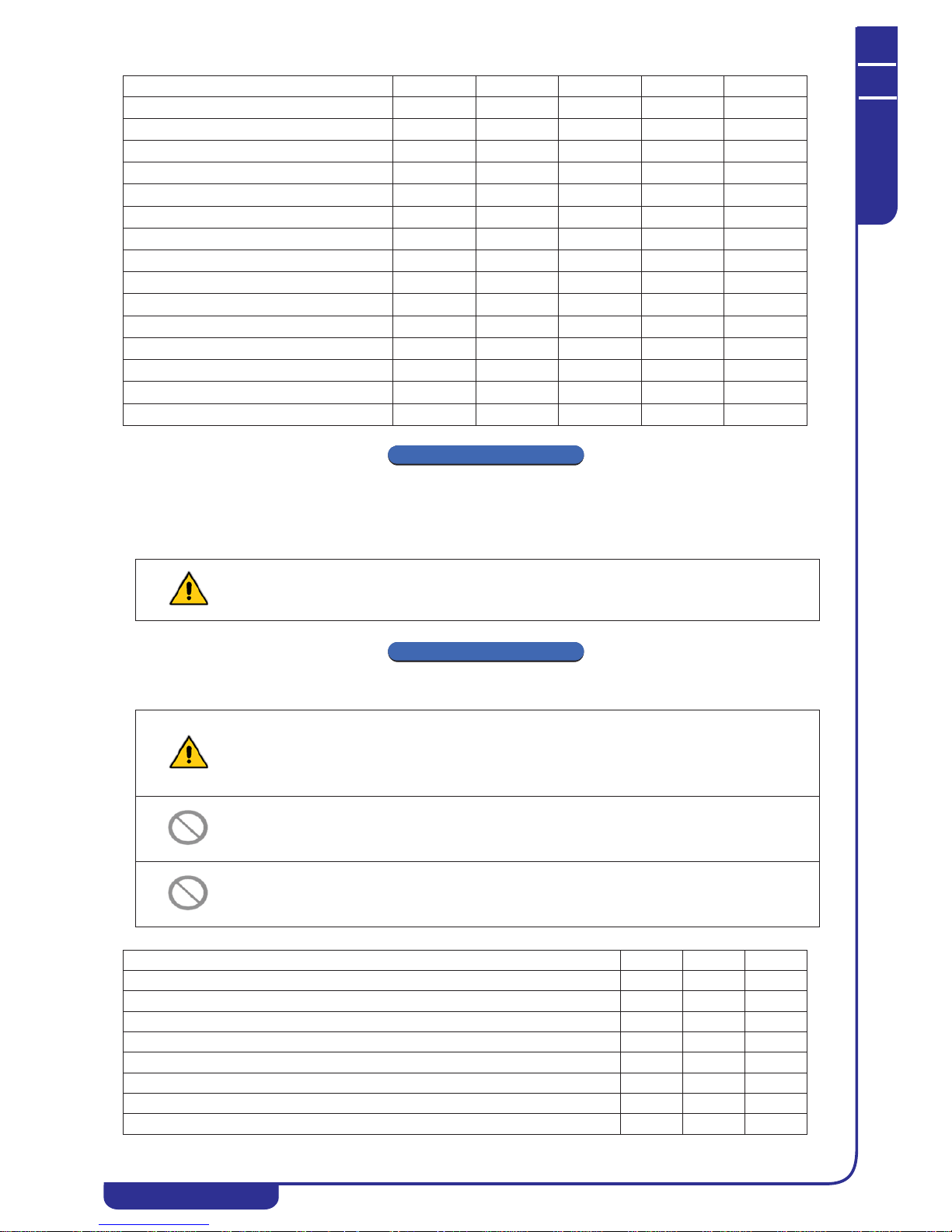
TECHNICAL MANUAL
Chapter 10 - Length shut-downs
NGSi 05÷15
39
ENGLISH
EN
The data in this manual are not binding and they can be modified by the manufacturer without notice. Reproduction of this manual is strictly prohibited
CHAPTER 10
LENGTH SHUT-DOWNS
• Turn off the units by turning the switch of each device to “OFF”.
• Turn off the water taps.
• Turn the master switch to “OFF”.
CHAPTER 11
ROUTINE CHECKS AND MAINTENANCE
Regular inspections should be performed to ensure that the unit is operating correctly:
Compressor not connected to power supply E79
OFF OFF
Inverter timeout E80
OFF OFF
Intake water probe E61
OFFOFFOFFOFF
Output water probe E62
OFFOFFOFFOFF
Compressor intake probe E63
OFFOFFOFFOFF
Compressor output probe + high pressure switch E64
OFFOFFOFFOFF
High pressure transducer E65
OFFOFFOFFOFF
Low pressure transducer E66
OFFOFFOFFOFF
External air probe for weather control E67
OFFOFFOFFOFF
Domestic hot water tank probe (optional) E69
OFFOFFOFFOFF
Flow switch E06
OFFOFFOFFOFF
High temperature E18
OFF OFF
High pressure E01
OFF OFF
Low pressure E02
OFF OFF
Anti-freeze alarm E05
OFF ON OFF OFF
If the temperature drops below zero there is a serious risk of freezing: fill the system with a mixture of water and glycol, or
drain the water system and heat pump water circuits.
WARNING:
All the operations described in this section MUST ALWAYS BE PERFORMED BY QUALIFIED STAFF. Before doing any
work on the unit or accessing internal parts, make sure that the electricity supply has been disconnected. The compressor
heads and delivery pipeline are often at quite high temperatures. Take special care when working in the vicinity of the heat
exchanger coils. The aluminium fans are particularly sharp and may cause serious injuries. After maintenance procedures,
put the panels back in place, securing them with the fixing screws.
The cooling circuits must not be charged with a refrigerant different from the one specified on the nameplate. Use of a
different refrigerant may seriously damage the compressor.
The use of oils other than those specified in this manual is forbidden. Use of a different oil may seriously damage the
compressor.
OPERATION 1 month 4 months 6 months
Filling of water circuit. x
Presence of bubbles in water circuit. x
Check that monitoring and safety devices are operating correctly. x
Check that there are no oil leaks from the compressor. x
Check that there are no water leaks in the water circuit. x
Check that the flow switch is operating correctly. x
Check that the crankcase heaters are powered up and operational. x
Clean the metal filters in the water circuit. x
Type of failure Code Compressor Pump Heaters Fan
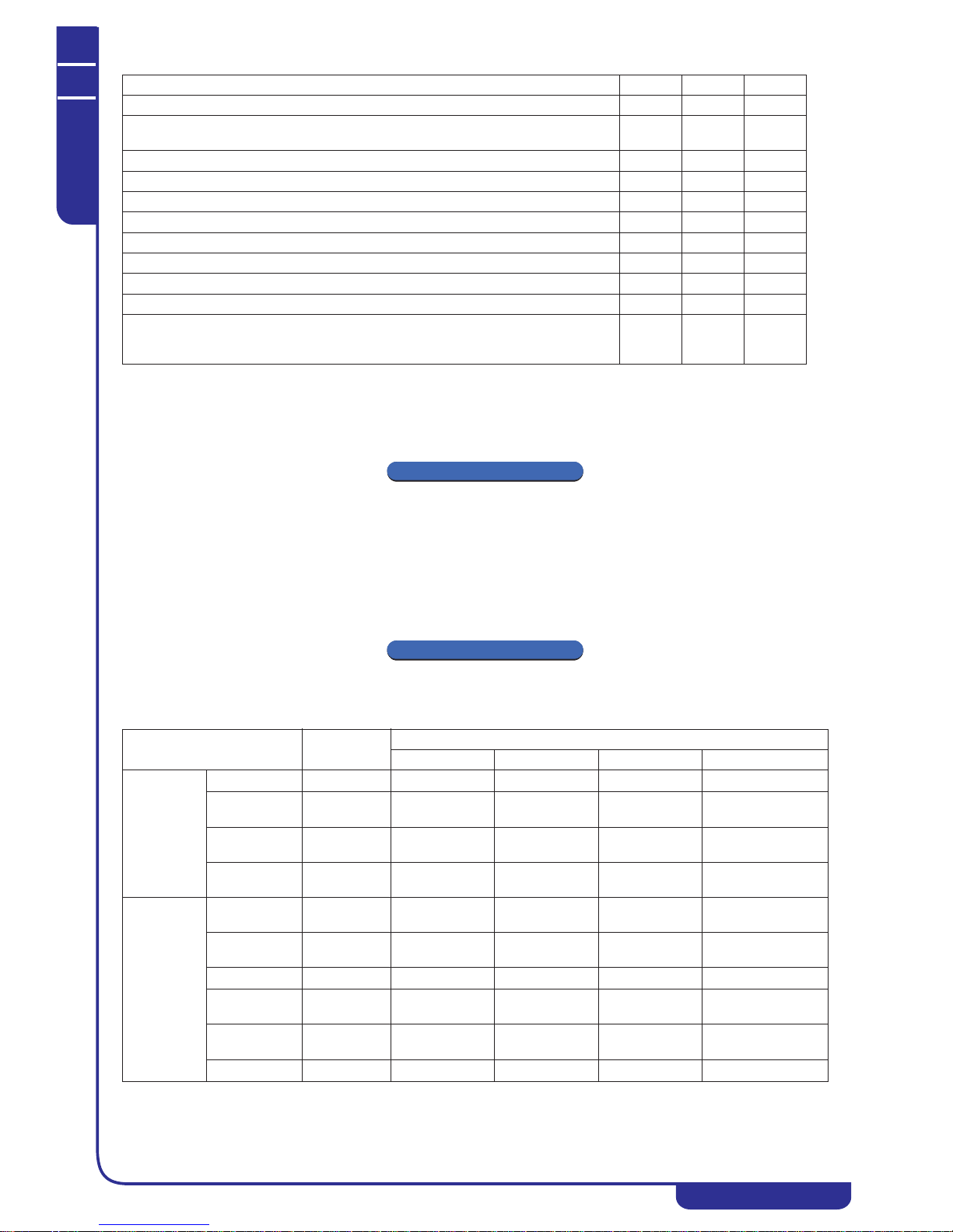
TECHNICAL MANUAL
Chapter 12 - Taking the unit out of service
NGSi 05÷15
40
ENGLISH
EN
The data in this manual are not binding and they can be modified by the manufacturer without notice. Reproduction of this manual is strictly prohibited
11.1 Environmental protection
The law regulating the use of ozone-depleting substances forbids the discharge of refrigerant gases into the environment. They must be
recovered and returned to the disposal centres provided at the end of their useful life. R410A is one of the refrigerants subjected to specific
control mechanisms enforced by law and its users must therefore comply with the requirements set out above. Special care must therefore be
taken during maintenance, to minimise any refrigerant leaks.
CHAPTER 12
TAKING THE UNIT OUT OF SERVICE
A number of recommendations must be followed when the unit reaches the end of its working life and therefore needs to be replaced:
• the refrigerant must be recovered by specialist staff and sent to the disposal centres;
• the compressor lubricating oil must also be recovered and sent to the disposal centres;
• if they are not usable, the structure and the various components must be dismantled and subdivided by type, especially the
copper and aluminium, of which the unit contains fairly large amounts.
These procedures facilitate the recovery and recycling of the substances concerned, thus reducing environmental impact.
CHAPTER 13
TECHNICAL DATA
Clean the finned coil exchangers using compressed air or a jet of water. x
Check that the electric terminals inside both the control panel and the compressor terminal boards
are securely fixed.
x
Tightness of water connections. x
Check that the fans are well fixed and balanced. x
Correct electrical voltage. x
Correct power drawdown. x
Check on the charge of refrigerant. x
Check on working pressure, overheating and under-cooling. x
Operation of circulator pump. x
Check on expansion vessel. x
If the unit is to be out of use for a long time, drain the water from the pipelines and heat
exchanger. This is essential if room temperatures below the freezing point of the fluid used are
expected during the lay-off.
x
Technical features
Unit of
measurement
Model
NGSi 05 NGSi 07 NGSi 10 NGSi 15
Electrical data
Power supply
230V/1/50Hz 230V/1/50Hz 230V/1/50Hz 400V/3+N+PE/50Hz
Max. power
drawdown
kW 2.81 4.61 5.78 7.93
Maximum
starting current
A 7.9 13.0 16.4 7.5
Maximum current
drawdown
A 12.3 20.2 25.4 11.5
Cooling
Cooling capacity
(1)
kW 4.13 6.49 8.20 10.51
Power drawdown
(1)
kW 1.33 2.08 2.65 3.39
E.E.R. (1)
W/W 3.11 3.12 3.10 3.10
Cooling capacity
(2)
kW 5.72 8.93 12.36 14.00
Power drawdown
(2)
kW 1.44 2.27 2.98 3.64
E.E.R. (2)
W/W 3.98 3.93 4.15 3.85
OPERATION 1 month 4 months 6 months

TECHNICAL MANUAL
Chapter 13 - Technical data
NGSi 05÷15
41
ENGLISH
EN
The data in this manual are not binding and they can be modified by the manufacturer without notice. Reproduction of this manual is strictly prohibited
Heating
Heating capacity
(3)
kW 5.48 8.43 11.81 13.38
Power drawdown
(3)
kW 1.65 2.55 3.45 4.13
C.O.P. (3)
W/W 3.32 3.30 3.42 3.24
Heating capacity
(4)
kW 5.77 9.06 12.40 14.16
Power drawdown
(4)
kW 1.39 2.21 2.95 3.45
C.O.P. (4)
W/W 4.15 4.11 4.21 4.11
Compressor
Type
Rotary
DC Inverter
Rotary
DC Inverter
Twin Rotary
DC inverter
Scroll
DC inverter
Number
111 1
Refrigerant oil
(type, quantity)
mL
ESTER OIL
VG74, 480
ESTER OIL
VG74, 820
FV50S, 1070 FV50S/1400
Fans
Type
Brushless DC
motor
Brushless DC
motor
Brushless DC
motor
Brushless DC motor
Number
112 2
Rated power
drawdown
kW 0.156 0.188 0.180 (×2) 0.180 (×2)
Rated current
drawdown
A 0.48 0.57 0.55 (×2) 0.55 (×2)
Speed
r/min 900 900 1.000 1.000
Maximum air
flow
m3/s
1.08 1.63 2.11 2.59
Refrigerant
gases
Type
R410A R410A R410A R410A
Quantity of
refrigerant
kg 1.55 2.10 3.65 3.90
Design pressure
(high/low)
MPa 4.2/1.5 4.2/1.5 4.2/1.5 4.2/1.5
Water circuit
Water flow rate
(4)
L/s 0.29 0.45 0.59 0.72
Usable head (4)
kPa 43 29 51 48
Pump rated
power (4)
kW 0.094 0.102 0.125 0.136
Pump maximum
power
kW 0.124 0.124 0.165 0.165
Pump maximum
current
drawdown
A 0.55 0.55 0.75 0.75
Expansion vessel
L222 2
Water
connections
inches 1”M 1”M 1”M 1”M
Minimum water
volume
L18 25 35 45
Noise level
Sound level
power (5)
dB(A) 63 65 67 68
Sound pressure
(6)
dB(A) 50 52 54 55
Dimensions
and weights
Dimensions
(W×H×D)
mm 1134x719x376 1229x861x371 1258×1402×448 1258×1402×448
Max. packaging
dimensions
(WxHxD)
mm 1310x850x430 1310x1000x430 1430x1546x690 1430x1546x690
Operating weight
kg 73 92 147 152
Net/gross weight
kg 69/77 87/96 140/153 145/158
Technical features
Unit of
measurement
Model
NGSi 05 NGSi 07 NGSi 10 NGSi 15

TECHNICAL MANUAL
Chapter 14 - Electrical data of unit and control devices
NGSi 05÷15
42
ENGLISH
EN
The data in this manual are not binding and they can be modified by the manufacturer without notice. Reproduction of this manual is strictly prohibited
Performance figures relate to the following conditions:
(1) Cooling: external air temperature 35°C; intake/outlet water temperature 12/7°C.
(2) Cooling: external air temperature 35°C; intake/outlet water temperature 23/18°C.
(3) Heating: external air temperature 7°C d.b. 6°C w.b.; intake/outlet water temperature 40/45°C.
(4) Heating: external air temperature 7°C d.b. 6°C w.b.; intake/outlet water temperature 30/35°C.
(5) Sound level power: determined based on the measurements carried out in accordance with ISO 3744.
(6) Sound pressure at 1 m obtained in free field over a reflecting plane. Tolerance values ± 2 dB. Sound levels refer to the unit under
maximum operating conditions. The data refer to the operating conditions with outside air temp 35°C, water temp. 7/12°C.
NOTE
The stated performance data are guideline and may be subject to variation.
Furthermore, the yields stated in points (1), (2), (3) and (4) are to be understood referring to the instantaneous power according to EN
14511.
CHAPTER 14
ELECTRICAL DATA OF UNIT AND CONTROL DEVICES
* For sizes 05, 07 and 10
** For size 15
NOTE
Electrical data are subject to variation due to updates. Therefore, users should always refer to the technical data sticker on the unit’s right
hand side panel.
CHAPTER 15
HEAT PUMP WORKING HEADS
Blow are shown the head-flow rate curves net of hydronic kit pressure drop. Each curve shows the optimal operating point under the
conditions specified at the peak (4) of Chapter 13 “Technical data”.
The system must be designed in a manner which guarantees the nominal flow rates for the duty points specified below.
15.1 Mod. NGSi 05
WARNING:
The minimum temperature allowed for the unit storage is 5°C.
Unit power supply
V/~/Hz
230/1/50 *
400/3+N+PE/50
**
Remote control circuit
V/~/Hz 12/1/50
On-board control circuit
V/~/Hz 12/1/50
Fan power supply
V/~/Hz 230/1/50
0
10
20
30
40
50
60
70
0,60,81,01,21,41,6
Water flow rate [m3/h]
Work head [kPa]
Flow rate [m3/h]

TECHNICAL MANUAL
Chapter 15 - Heat pump working heads
NGSi 05÷15
43
ENGLISH
EN
The data in this manual are not binding and they can be modified by the manufacturer without notice. Reproduction of this manual is strictly prohibited
15.2 Mod. NGSi 07
15.3 Mod. NGSi 10
15.4 Mod. NGSi 15
0
10
20
30
40
50
60
1,0 1,2 1,4 1,8 2,0 2,2
1,6
Work head [kPa]
Flow rate [m3/h]
0
10
20
30
40
50
60
70
1,3 1,5 1,7 1,9 2,1 2,3 2,5 2,7 2,9 3,1 3,3 3,5
Work head [kPa]
Flow rate [m3/h]
0
10
20
30
40
50
60
70
1,6 1,8 2,0 2,2 2,4 2,6 2,8 3,0 3,2 3,4 3,6 3,8 4,0 4,2
Work head [kPa]
Flow rate [m3/h]

TECHNICAL MANUAL
Chapter 16 - Operating limits
NGSi 05÷15
44
ENGLISH
EN
The data in this manual are not binding and they can be modified by the manufacturer without notice. Reproduction of this manual is strictly prohibited
CHAPTER 16
OPERATING LIMITS
16.1 Evaporator water flow rate
The nominal flow rate refers to a temperature difference of 5°C between the evaporator intake and outlet. The maximum permitted flow rate
occurs with a temperature difference of 3°C. Higher values may cause excessively high pressure drops. The minimum permitted flow rate
occurs with a temperature difference of 8°C (except for the model NGSi 05 for which a maximum temperature difference of 6.25°C is
allowed). Insufficient flow rates may cause excessively low evaporation temperatures, tripping the safety devices and causing the unit to cut
out, and in extreme cases even causing ice to form in the evaporator, leading to serious damage to the cooling circuit.
For greater precision, the table below shows the minimum flow rates to be assured at the plate heat exchanger to guarantee correct operation for
each model (N.B.: the water flow switch is provided as protection against failed tripping of the antifreeze probe due to low flow rate; it does not
guarantee the minimum water flow rate required for correct operation of the unit).
As a basic guide, if no other measurement systems are available, the correct flow rate for assuring the best performance from the unit can be
checked, with the circulator pump at maximum rpm, by using a pressure gauge to measure the pressure difference between the water return
and output lines on the unit’s external water connections, and ensure that this value is at least as high as the working heads shown on the
curves provided in Chapter 15 “Heat pump working heads” for the respective models.
16.2 Chilled water production (summer operation)
The minimum temperature permitted at the evaporator output is 5°; for lower temperatures, structural modifications must be made to the
unit. In this case, contact our technical department for the feasibility and specification of the modifications to be made depending on
requirements. The maximum temperature which can be maintained during normal operation at the evaporator outlet is 25°C. Higher
temperatures (up to a maximum of 40°C) can be tolerated in transients and during start-up. In all case, the maximum power drawdown is
during operation in heat pump mode with outlet water at 55°C and external temperature of -10°C.
16.3 Hot water production (winter operation)
Once the system is in normal operation, the water intake temperature must drop below 25°C; except during transients or start-up, lower
values may cause system malfunctions with possible compressor failures. The maximum outlet water temperature must not exceed 55°C. At
this temperature, electricity drawdown and COP are optimised if the external temperature is over 5°C, although the unit is able to operate
down to the limit of -15°C.
For temperatures above those indicated, especially with low water flow rates, unit malfunctions may occur, or in the most critical cases the
safety devices may be tripped.
16.4 Room air temperature and summary table
Units are designed and built to operate in summer mode, with condensation control, with an external air temperature between -10°C and
46°C. During operation in heat pump mode, the permitted external air temperature range is from -15°C to +40°C, depending on the outlet
water temperature as shown in the table below.
Operating limits
Model NGSi 05 NGSi 07 NGSi 10 NGSi 15
Rated cooling power [kW]
5.67 8.93 11.90 14.36
Minimum water flow rate to by guaranteed [L/s]
0.217 0.267 0.355 0.429
Water chiller mode
Room temperature
Minimum -10°C Maximum +46°C
Outlet water temperature
Minimum +5°C Maximum +25°C
Heat pump mode
Room temperature
Minimum -15°C Maximum +30°C
Outlet water temperature
Minimum +25°C Maximum +55°C
Heat pump mode for domestic hot water
Room temperature with water at 48°C max.
Minimum -15°C Maximum +40°C
Room temperature with water at 55°C max.
Minimum -15°C Maximum +35°C
Outlet water temperature
Minimum +20°C Maximum +55°C

TECHNICAL MANUAL
Chapter 17 - Correction factors for the use of glycol
NGSi 05÷15
45
ENGLISH
EN
The data in this manual are not binding and they can be modified by the manufacturer without notice. Reproduction of this manual is strictly prohibited
CHAPTER 17
CORRECTION FACTORS FOR THE USE OF GLYCOL
CCF: Chilling correction factor
IPCF: Input power correction factor
WFCF: Water flow correction factor
PDCF: Pressure drop correction factor.
The water flow and pressure drop correction factors must be applied to values obtained without the use of glycol. The water flow correction
factor is calculated in order to maintain the temperature difference achieved without the use of glycol. The pressure drop correction factor is
applied to the water flow rate corrected by the water flow correction factor.
CHAPTER 18
DIMENSIONS
18.1 Mod. NGSi 05
IN/OUT:1”M
Percentage of glycol Freezing point (°C) CCF IPCF WFCF PDCF
10% -3.2 0.985 1 1.02 1.08
20% -7.8 0.98 0.99 1.05 1.12
30% -14.1 0.97 0.98 1.10 1.22
40% -22.3 0.965 0.97 1.14 1.25
50% -33.8 0.955 0.965 1.2 1.33

TECHNICAL MANUAL
Chapter 18 - Dimensions
NGSi 05÷15
46
ENGLISH
EN
The data in this manual are not binding and they can be modified by the manufacturer without notice. Reproduction of this manual is strictly prohibited
18.2 Mod. NGSi 07
IN/OUT: 1”M
18.3 Mod. NGSi 10-15
IN/OUT: 1”M

TECHNICAL MANUAL
Chapter 19 - Electric wiring diagrams
NGSi 05÷15
47
ENGLISH
EN
The data in this manual are not binding and they can be modified by the manufacturer without notice. Reproduction of this manual is strictly prohibited
CHAPTER 19
ELECTRIC WIRING DIAGRAMS
19.1 Mod. NGSi 05-07
(*) It is necessary to setting the correct parameters. P ossible other resource configurations.
(**) Digital outputs are not available if it is p resent AK version.

TECHNICAL MANUAL
Chapter 19 - Electric wiring diagrams
NGSi 05÷15
48
ENGLISH
EN
The data in this manual are not binding and they can be modified by the manufacturer without notice. Reproduction of this manual is strictly prohibited
19.2 Mod. NGSi 10
Temp Sensor
Heat Sink
(*) It is necessary to setting the correct parameters.
Possible other resource configurations.
(**) Digital outputs are not available if it is prese nt AK version.

TECHNICAL MANUAL
Chapter 19 - Electric wiring diagrams
NGSi 05÷15
49
ENGLISH
EN
The data in this manual are not binding and they can be modified by the manufacturer without notice. Reproduction of this manual is strictly prohibited
19.3 Mod. NGSi 15
(*) It is necessary to se tting the correct
parameters. Possible other resource configurat ions.
(**) Digital outputs are not available if it is
present AK version.

TECHNICAL MANUAL
Chapter 20 - CRH remote keypad (optional accessory)
NGSi 05÷15
50
ENGLISH
EN
The data in this manual are not binding and they can be modified by the manufacturer without notice. Reproduction of this manual is strictly prohibited
CHAPTER 20
CRH REMOTE KEYPAD (OPTIONAL ACCESSORY)
The CRH remote keypad allows the user to set the operating mode of chillers and fancoils connected in an RS485 network. The network may
consist of up to 5 cascade-connected chillers and up to 70 fancoils, subdivided into 9 temperature control zones. The keypad can be fixed to
the E503 inset wall-mounting boxes.
For further information, please refer to the specific manual for the CRH.
20.1 Connecting the CRH keypad to the minichiller
The connection between the CRH panel, the minichillers and the terminal units is very simple: it is made using a series-connected 2x0.5mm2
screened twisted pair.
CHAPTER 21
DOUBLE SETPOINT KIT (OPTIONAL ACCESSORY)
21.1 Scope and field of application
The double setpoint function adds a second working setpoint on the system side (in both cooling and heating modes).
They are mainly used in the case of underfloor cooling systems with dehumidification fan coils.
The purpose of the application is to prevent condensation from forming on the floor in any conditions and to ensure comfortable temperature
and humidity conditions at all times.
5: connect to the GNDR reference terminal of the
unit output terminal board;
6: connect to the R- output terminal of the unit
output terminal board;
7: connect to the R+ output terminal of the unit
output terminal board;
8: connect to the 12V- output terminal of the unit
output terminal board;
9: connect to the 12V+ output terminal of the unit
output terminal board.
ESC: back to previous
menu level
F1: access to menus and
submenus
F2: select unit and
modify parameter value
ENTER: access to
DOWN: decrease the
parameter value or
UP: increase the parameter
value or scroll menu
scroll menu
submenu and confirm
parameter value

TECHNICAL MANUAL
Chapter 21 - Double setpoint kit (optional accessory)
NGSi 05÷15
51
ENGLISH
EN
The data in this manual are not binding and they can be modified by the manufacturer without notice. Reproduction of this manual is strictly prohibited
21.2 Kit components and technical data
Humidity switch
DIN bar socket
Relay
21.3 Humidity switch mode operation
The dewpoint is calculated by means of the internal temperature and humidity probe reading.
The room temperature measured by the probe inside the controller is compared with the dewpoint (calculated at the last moment of tAr)
added to parameters odr and Hy:
• if Tr<Tint<Tr+odr ĺ the relay is activated for the whole of the next time tAr
• if Tr+odr<Tint<Tr+odr+Hy ĺ the relay is activated for the % value of tAr selected on the ramp
• if Tint<Tr+odr+Hy ĺ the relay is deactivated for whole of the next time tAr
Parameters tAr, odr and Hy are set in the factory and cannot be modified.
• power supply 12-24 Vac
• internal temperature and humidity probe
• trimmer for setting an offset of -3 to +3°C in
relation to the dewpoint
• RS485 serial
• for application on DIN bar
• maximum current per pole: 10 A
• 230V DC power supply
• maximum resistive load per pole: 8 A
• maximum inductive load per pole: 1.6 A

TECHNICAL MANUAL
Chapter 21 - Double setpoint kit (optional accessory)
NGSi 05÷15
52
ENGLISH
EN
The data in this manual are not binding and they can be modified by the manufacturer without notice. Reproduction of this manual is strictly prohibited
21.4 Minichiller settings
Double setpoint mode setting parameter H82 (from maintenance menu):
Inputs/outputs setting:
• H44=26 for the digital input DI7 setting (SE-SE terminals)
• H62=25 for the digital output DI7 setting OC2 (NC2,N2,NO2 terminals)
21.5 Installation notes
Humidity switch
The humidity switch relay must be connected as NC.
There are two possible options:
1. dehumidification not necessary (double setpoint activation):
when the relay is not activated, water is sent to the floor system (second setpoint)
2. dehumidification necessary (double setpoint deactivation):
when the relay is activated, water is sent to the fancoils (second setpoint)
Relay
The three-way valve can be connected directly to the relay with switching contact on the unit (5A resistive, 1A inductive, 230 VAC),
connecting it to terminals NC2, N2 and NO2 (if a valve with 3-point power supply is available), or to terminals N2-NC2 (if the valve
available has 2-point power supply, with return spring).
However, an external relay, including in the double setpoint kit, should be used to allow connection with higher loads (up to 8A resistive,
1,6A inductive) and at the same time to separate the power supply lines of the minichiller, three-way valve and fancoil (in this case, suitable
electrical protection must be provided for the fancoil power supply line).
In this second case, the relay must be installed on DIN bar of the user terminal board on the unit, connecting the power supply to terminals
N2-NC2. The three-way valve must then be connected to the NO COM NC relay outputs if it has 3-point power supply, or to NO-COM with
2-point power supply with return spring.
For setting these parameters, refer to the tables in Point 9.25, while for the electrical connections refer to the electrical diagrams in Point
21.8.
Three-way valve with 2 or 3 point power supply (not included in kit)
The three-way valve is used to divert the flow between the floor system and the fancoils.
For three-way valves with 2 point power supply (return spring), the default line must be connected to the floor system.
For three-way valves with 3 point power supply, the valve line with the water connection to the floor system must receive power as shown in
the wiring diagrams provided in Point 21.8. In these diagrams, the floor side or system side is the line to which the valve must switch when
it receives power.
21.6 Settable setpoints
Use the SET key to set the setpoints from the panel on the unit.
H82 OPERATION
0 Pop-up selection menu appears on CRH
1 Standard mode
2 Double setpoint active in summer
3 Double setpoint active in winter
4 Double setpoint active in summer and winter
Setpoint type Setpoint (summer/winter) Summer Winter
First setpoint (°C)
Coo/Hea 7 (5÷18) 45 (35÷55)
Second setpoint (°C)
Co2/He2 18 (7÷23) 35 (25÷45)
100
0
Tempo di ON del relé rispetto a tAr
Hy
odr
T
int
[°C/°F]
Punto
Rugiada
Punto
Rugiada
+ odr
% OUTPUT
Relay ON time in relation to tAr
Dew
point
Dew
point + odr

TECHNICAL MANUAL
Chapter 21 - Double setpoint kit (optional accessory)
NGSi 05÷15
53
ENGLISH
EN
The data in this manual are not binding and they can be modified by the manufacturer without notice. Reproduction of this manual is strictly prohibited
The second setpoint is higher than the first setpoint in summer and lower in winter:
• in summer: T2 >= T
• in winter: T2 <= T
21.7 Switching functions
Switching sequence from normal setpoint to second setpoint:
1. working setpoint change
2. in summer: 3-way valve only switches when the second setpoint – 5°C has been reached
in winter: 3-way valve only switches when the second setpoint + 5°C has been reached
(switching always takes place 5 min after the setpoint change)
Switching sequence from second setpoint to normal setpoint:
1. 3-way valve switches
2. working setpoint changes after a parameter-controlled time equal to opening of the three-way valve (default b04=30s from
maintenance menu)
21.8 Electrical wiring diagram
In these diagrams, the domestic hot water tank, system, floor side or fancoil side is the line to which the valve must switch when the relative
connection receives power.
21.8.1 Wiring diagram, configuration without external relay
3-WAY VALVE
DOMESTIC HOT WATER
3-WAY VALVE
DOUBLE SETPOINT
Connection for valve with 3-point power supply only, system side
Domestic hot water tank side
Fancoil side
Connection for valve with 3-point power supply only
floor side
NC2-N2 connection for fan coil consent
Maximum permitted resistive load: 5 A
Maximum permitted inductive load: 1 A
Remote control
serial
Double humidity switch for
NC contact setpoint
Auxiliary heater
220V SA
Sensor
domestic hot water
Summer/Winter
On/Off
remote
Remote control + humidity
switch power supply

TECHNICAL MANUAL
Chapter 21 - Double setpoint kit (optional accessory)
NGSi 05÷15
54
ENGLISH
EN
The data in this manual are not binding and they can be modified by the manufacturer without notice. Reproduction of this manual is strictly prohibited
21.8.2 Wiring diagram, configuration with external relay
21.9 Humidity switch connections
Make the following connections between the humidity switch and the minichiller terminal board:
• connect POWER SUPPLY to 12V+ and 12V-
• connect RELAY-C/NC to the two SE terminals
WARNING:
If a double setpoint three-way valve with three point power supply is used in the configuration with external relay, the valve is
live even when the minichiller is OFF or is switched off using the internal circuit breaker. In the event of a system malfunction,
always disconnect the power supply using the external circuit breaker.
3-WAY VALVE
DOMESTIC
3-WAY VALVE
DOUBLE SETPOINT
Connection for valve with 3-point power supply only, system side
Domestic hot water tank side
Fancoil side
* floor side
Relay
Finder
Remote control
serial
Remote control + humidity
switch power supply
Double humidity switch for
NC contact setpoint
Auxiliary heater
220V 5A
Sensor
domestic hot water
Summer/Winter
On/Off
remote
* Connection for valve with 3-point power supply only
11-14 on relay: clean NO contact for fan coil enabling
Maximum permitted resistive load: 8 A
Maximum permitted inductive load: 1.6 A
HOT WATER
Analogue
output
RS485
serial
Power supply
12-24 Vac/dc
Digital
input
External
probe

TECHNICAL MANUAL
Chapter 21 - Double setpoint kit (optional accessory)
NGSi 05÷15
55
ENGLISH
EN
The data in this manual are not binding and they can be modified by the manufacturer without notice. Reproduction of this manual is strictly prohibited
21.10 Standard water system diagram
Underfloor
heating system
Fan coil
3-way valve
Double setpoint
(VD accessory)
3-way valve for
domestic hot water
(VD accessory)
Hot water storage tank
Mains water
Water Probe
Domestic hot
water
(SAS accessory)

 Loading...