

MTA HAST 090 N, HAST 110 N, HAST 080 N, HAST 140 N, HAST 070 SN Maintenance And Operating Manual
...
HEAT PUMPS
MAINTENANCE AND OPERATING MANUAL
HAS T 070÷140
38178801085
Original instructions in Italian language

MAINTENANCE AND OPERATING MANUAL
Quick guide
HAS T 070÷140
1
ENGLISH
EN
The data in this manual are not binding and they can be modified by the manufacturer without notice. Reproduction of this manual is strictly prohibited.
QUICK GUIDE
0.1 Power up and power down
Power up the machine.
At the time of commissioning, follow the machine configuration instructions (see "6.2.1 First power-up").
The display switches on and the main mask appears.
Check the unit status and the presence of blocking alarms.
Hold down the key for 2 sec
. The pump, if installed, will start running and the unit's refrigerant compressors will start
after a preset time lag.
To stop the unit hold down the key for 2 seconds.
The electronic controller and the display will remain on.
0.2 Keys
Summary table showing all types of keys present on the controller.
Key Function
Scroll through masks
Scroll and select the fields in a mask / increase and decrease the value of a field
Scroll the parameters on different circuits (pronged press)
Scroll the masks in the ALARM menu
Access the I/O menu (see "6.3 I/O menu")
Access the SET menu (see "6.4 Setpoints Menu")
Access the USER menu (see "6.5 User Menu")
Access the reserved menu (see "6.7 Reserved menu")
Access the ALARM menu (see "6.8 Alarms")
Power the unit on and off (see "6.2.4 Powering up the unit")
Exit a menu
Activate a field/confirmation
Alarms reset in ALARM menu (see "6.8 Alarms")
Access to EX/MD submenu from I/O menu (optional, see "6.3 I/O menu")

MAINTENANCE AND OPERATING MANUAL
Quick guide
HAS T 070÷140
2
ENGLISH
EN
The data in this manual are not binding and they can be modified by the manufacturer without notice. Reproduction of this manual is strictly prohibited.
0.3 Changing the setpoint
0.4 Alarms
The unit can be either on or off.
Press in the main menu to open the setpoint menu.
Scroll through the menu with the keys until reaching mask ST02.
Use the key to select the setpoint.
Press .
Use the keys to set the value.
Press to confirm.
Press to quit the menu.
The presence of active alarms is signalled by the icon.
Press the key to enter the mask to display the alarms.
The mask contains a list of active alarms. Use the keys to scroll
the list.
The symbol shows that the alarm is resettable.
Press to reset an individual alarm.
Press and keep it pressed for 2 seconds to reset all active alarms.
Press to quit the mask.

MAINTENANCE AND OPERATING MANUAL
Contents
HAS T 070÷140
3
ENGLISH
EN
The data in this manual are not binding and they can be modified by the manufacturer without notice. Reproduction of this manual is strictly prohibited.
CONTENTS
QUICK GUIDE ......................................................................................................................................1
0.1 Power up and power down...............................................................................1
0.2 Keys..................................................................................................................1
0.3 Changing the setpoint.......................................................................................2
0.4 Alarms ..............................................................................................................2
CONTENTS...........................................................................................................................................3
G
ENERAL INFORMATION....................................................................................................................5
1.1 How to interpret the model...............................................................................5
1.2 How to interpret the codes ...............................................................................5
1.3 Data plate..........................................................................................................6
1.4 Declaration of conformity ................................................................................6
1.5 Performance data..............................................................................................7
1.6 Noise ................................................................................................................7
1.7 How to interpret the alphanumeric string.........................................................7
TECHNICAL PARAMETERS FOR HEAT PUMP SPACE HEATERS AND HEAT PUMP
COMBINATION
HEATERS.....................................................................................................................7
S
AFETY ..............................................................................................................................................32
2.1 General ...........................................................................................................32
2.2 General precautions........................................................................................33
2.2.1 Precautions during lifting and transport ........................................................33
2.2.2 Precautions to be adopted during operation ..................................................33
2.2.3 Disposal .......................................................................................................... 33
2.2.4 Precautions for maintenance and repair ........................................................33
2.3 Refrigerants .................................................................................................... 34
DESCRIPTION ....................................................................................................................................35
3.1 Operating principle.........................................................................................35
3.2 Components....................................................................................................35
3.2.1 Compressors ...................................................................................................35
3.2.2 Condensers ......................................................................................................35
3.2.3 Fans ................................................................................................................36
3.2.4 Evaporator ......................................................................................................36
3.2.5 Heat recovery and desuperheater ...................................................................36
3.2.6 Liquid receiver ...............................................................................................37
3.2.7 Cycle reversal valve .............................................................................. ..........37
3.3 Hydraulic system (optional)...........................................................................38
3.4 Cabinet ...........................................................................................................39
3.5 Protection rating .............................................................................................39
3.6 Electrical circuit .............................................................................................39
3.7 Overall dimensions.........................................................................................39
INSTALLATION ..................................................................................................................................40
4.1 Foreword ........................................................................................................40
4.2 Symbols..........................................................................................................40
4.3 Installation......................................................................................................40
4.3.1 Inspection ................... ........................ ......................... ........................ ............ 40
4.3.2 Location .......................................................................................................... 40
4.3.3 Hydraulic connections ....................................................................................41
4.3.4 Freeze protection ............................................................................................44
4.3.5 Electrical connections .....................................................................................45
4.3.6 Phase Monitor .............. ...................................................................................45
START-UP ..........................................................................................................................................46
E
LECTRONIC CONTROLLER .............................................................................................................47
6.1 Technical features ..........................................................................................47
6.1.1 Controller connectivity ...................................................................................47
6.1.2 Display ..................... .......................................... .......................................... ...48
6.1.3 Auxiliary hardware .........................................................................................49

MAINTENANCE AND OPERATING MANUAL
Contents
HAS T 070÷140
4
ENGLISH
EN
The data in this manual are not binding and they can be modified by the manufacturer without notice. Reproduction of this manual is strictly prohibited.
6.2 Using the display ........................................................................................... 50
6.2.1 First power-up ................................................................................................ 50
6.2.2 Main menu ...................................................................................................... 51
6.2.3 Display menus ................................................................................................ 51
6.2.4 Powering up the unit ......................................... .............................................51
6.2.5 Power-on from a digital input ........................................................................ 51
6.2.6 Power-on by supervision system ........................................... ......................... 51
6.2.7 Keys ................................................................................................................ 52
6.2.8 Icons ............................................................................................................... 53
6.3 I/O menu ........................................................................................................ 54
6.3.1 EX/MD auxiliary I/Os ....................................... .............................................55
6.4 Setpoints Menu .............................................................................................. 57
6.5 User Menu...................................................................................................... 59
6.5.1 Autostart ......................................................................................................... 60
6.5.2 Display language ............................................................................................60
6.5.3 Buzzer ............................................................................................................. 60
6.5.4 Backlighting and contrast ........................................................................... .. . 60
6.6 Alarm Menu................................................................................................... 60
6.7 Reserved menu............................................................................................... 61
6.7.1 Reserved menu icons ......................................................................................61
6.7.2 Access to menu functions .... ................................. ................................. ..........62
6.7.3 Configuration ................................................................................................. 63
6.7.4 Compressors .................. ...................................... .................................... ....... 63
6.7.5 Fans ........................... ............................................... ...................................... 6 5
6.7.6 Anti-freeze ...................................................................................................... 67
6.7.7 Heat recovery ................................................................................................. 68
6.7.8 Regulation ...................................................................................................... 70
6.7.9 Defrost ..................... .............................................. ......................................... 7 2
6.7.10 Operating hours ........................................... .................................................. 73
6.7.11 Manual procedure ..........................................................................................73
6.7.12 Alarms set ......... .............................................................................................. 74
6.7.13 Log ............................. .......................... ........................... ........................... .....74
6.7.14 Pumps ............................................................................................................. 74
6.7.15 Date/time ........................................................................................................ 75
6.7.16 Time bands .....................................................................................................75
6.7.17 Modularity ...................................................................................................... 75
6.7.18 Supervision ........................................................ ............................................. 76
6.7.19 Unloading ....................................................................................................... 76
6.7.20 Special functions ............................................................................................. 77
6.7.21 Free-cooling ................................................................................................... 79
6.7.22 Other settings ........................................... ...................................................... 80
6.8 Alarms............................................................................................................ 80
6.8.1 Buzzer ............................................................................................................. 80
6.8.2 Alarms list ............. ............................................................... ........................... 80
FUNCTIONS AND COMPONENTS OF THE UNIT .................................................................................89
7.1 Electronic thermostatic valve (optional)........................................................ 89
7.2 High pressure switches (HP).......................................................................... 89
7.3 Temperature and pressure transducers........................................................... 89
7.3.1 Pressure transducers .......... ................................................................ ............90
7.4 Flow switch.................................................................................................... 90
7.5 Level sensor ................................................................................................... 90
7.6 Forced ventilation of the electrical board ...................................................... 91
7.7 Antifreeze control .......................................................................................... 91
OPERATION AND MAINTENANCE .....................................................................................................92
8.1 Operation ....................................................................................................... 92
8.2 Maintenance................................................................................................... 92
8.2.1 Access to the unit's internal compartments ................................................. ...92
8.2.2 Emptying of the evaporator ............................................................................93
8.2.3 Planning of checks and maintenance operations ........................................... 94
TROUBLESHOOTING .........................................................................................................................95
R
ISK ANALYSIS: RESIDUAL RISK......................................................................................................98
A
PPENDIX........................................................................................................................................101
10.1 Settings table ................................................................................................ 101

MAINTENANCE AND OPERATING MANUAL
General information
HAS T 070÷140
5
ENGLISH
EN
The data in this manual are not binding and they can be modified by the manufacturer without notice. Reproduction of this manual is strictly prohibited.
CHAPTER 1
GENERAL INFORMATION
These units are designed to cool or heat a liquid (WATER in the majority of applications).
The term “WATER” is used for the sake of simplicity to identify the liquid to be cooled, even if the liquid involved is not
water (for example mixtures of water and ethylene or propylene glycol).
The liquid to be cooled must be compatible with the materials used.
This analysis must be carried out when installing the unit.
ATTENTION
Requests for spare parts and any information must be addressed to the local dealer or service centre, specifying
the MODEL and SERIAL NUMBER shown on the unit's nameplate and on the last page of this manual.
1.1 How to interpret the model
1.2 How to interpret the codes
MODEL DESCRIPTION
H AS T
Unit version (N, SN or SSN)
Nominal power of compressor expressed in HP
HAries Tech model
H = Heat pump
/N
Low noise operation value: standard. Fan rotation speed approx. 900 rpm. Compressors compartment only
partially acoustically insulated.
/SN
Low noise operation value: medium. Fan rotation speed approx. 700 rpm. Acoustically insulated compressors
compartment.
/SSN
Low noise operation value: high. Fan rotation speed approx. 700 rpm. Compressors compartment with high
efficiency acoustic insulation.

MAINTENANCE AND OPERATING MANUAL
General information
HAS T 070÷140
6
ENGLISH
EN
The data in this manual are not binding and they can be modified by the manufacturer without notice. Reproduction of this manual is strictly prohibited.
1.3 Data plate
The data plate affixed to the unit shows the main technical data.
1.4 Declaration of conformity
MODEL and CODE Identify the size of the unit (see Chapter 1 “General information“) and the
type of construction.
MANUAL Code number of this manual.
SERIAL NUMBER Unit serial number or manufacturing number.
YEAR OF CONSTRUCTION Year of unit's final testing.
VOLTAGE/PHASES/FREQUENCY Power supply specifications.
MAX CURRENT INPUT
I
MAX
Unit current input in limit working conditions
INSTALLED POWER
P
MAX
Unit power input in limit working conditions
PROTECTION RATING Protection rating of the entire unit, according to European standard EN
60529.
REFRIGERANT Type of refrigerant charge with which the unit is filled.
REFRIGERANT CHARGE Quantity of refrigerant supplied to the circuit.
MAX. REFRIGERANT PRESS. HP SIDE Refrigerant circuit design pressure (high pressure side).
MAX. REFRIGERANT PRESS. LP SIDE Refrigerant circuit design pressure (low pressure side).
USER CIRC. FLUID Fluid cooled or heated by the unit (usually: water).
MAX. WORKING PRESSURE User circuit maximum design pressure.
MAX TEMPERATURE User circuit maximum design temperature - not to be confused with the
maximum working temperature, which is specified at the time of the offer.
SOUND PRESSURE LEVEL Free field sound pressure level in hemispherical radiation conditions
(open field) at a distance of 1 m from the condenser side of the unit and a
height of 1.6 m from the ground.
AMBIENT TEMPERATURE Thermal exchange air minimum and maximum temperature values.
WEIGHT Approximate weight of the unit without packaging.
List:
a) Name of manufacturer
b) Definition of responsibility
c) Type of unit
d) Model of the unit
e) Serial or construction number of the unit
f) Directives and standards
g) PED
h) Officer responsible for technical file
i) Particulars of the officer responsible for the technical file
j) Place and date
M.T.A. S.p.A.
V
IA ARTIGIANATO
,2-Z
ONA INDUSTRIALE
- 35026CONSELVE (PD)- ITALY
Dichiarazione di conformità CE / UE
a) Noi:
b) Dichiariamo sotto la nostra sola responsabilità che la macchina
c) Tipo:
d) Modello:
e) Matricola:
f) è conforme a quanto prescritto dalle Direttive e norme:
x Direttiva Macchine 2006 /42/CE
- UNI EN ISO 12100
- CEI EN 60204-1 : 2006-09
x Direttiva Compatibilità Elettromagnetica 2 014/30/UE
- CEI EN 61000-6-1 : 2007-10
- CEI EN 61000-6-3 : 2007-11
- CEI EN 61000-6-2 : 2006-10
- CEI EN 61000-6-4 : 2007-11
g) inoltre è stata progettata, costruita e ispezionata conformemente
ai requisiti richiesti dalla Direttiva PED 2014/68/UE
-EN 378
x l’insieme ricade in categoria:
x la procedura di valutazione di conformità utilizzata è secondo il modulo:
(rif. Allegati II e III della Direttiva 2014/68/UE)
x l’organismo notificato i ncaricato della sorveglianza del sistema di qualità:
x estremi dell'Attestato di approvazione del sistema qualità:
x la macchina è considerata insieme ai fini della direttiva PED. Le attrezzature in pressione che la
compongono e le relative procedure di valutazione di conformità sono le seguenti:
Gli altri componenti non recano la marcatura CE in quanto rientrano nelle prescrizioni dell’Art. 1
par. 2 f della Direttiva 2014/68/UE
h) che la persona autorizzata alla costituzione del fascicolo tecnico è:
indirizzo:
i) Nome:
Cognome: Posizione:
j)
Luogo, Data Firma
Allegati: Lista dei pericoli considerati secondo l’Allegato I della Direttiva Macchine
MUT002/H
FACS
I
MI
LE

MAINTENANCE AND OPERATING MANUAL
Technical parameters for heat pump space heaters and heat pump combination heaters
HAS T 070÷140
7
ENGLISH
EN
The data in this manual are not binding and they can be modified by the manufacturer without notice. Reproduction of this manual is strictly prohibited.
1.5 Performance data
The performance of the unit depends mainly on the flow rate and the temperature of chilled water (CHILLER) or heated
water (HEAT PUMP) and on the ambient temperature.
Performance values are defined at the time of the contract, refer to the offer data if necessary.
1.6 Noise
Data concerning noise levels are shown in the appendix to the manual.
1.7 How to interpret the alphanumeric string
ATTENTION
See the tabl e concerning the alphanumeric string in th e appendix.
The alphanumeric string is shown on the metal data plate on the cover page of this manual.
TECHNICAL PA RAMETERS FOR HEAT PUMP SPACE HEATERS AND HEAT PUMP
COMBINATION HEATERS
Parameters shall be declared for medium-temperature application, except for low-temperature heat pumps.
For low temperature heat pumps, parameters shall be declared for low-temperature application.
Parameters shall be declared for average climate conditions.
This symbol shown alongside appears in some refrigerant circuit diagrams and electrical
diagrams. This symbol refers to the alphanumeric string reported in the manual. The upper
box (X) identifies the position of the string, the lower box (Y) identifies the assigned value.
The empty alphanumerical string is circled in the adjacent figure; each
position in the upper row is associated with an alphanumeric value in the
lower row (0, 1, 2, A, B, etc.) and each character is associated with a
specific feature of the unit.
Model/Version HAS T 0 7 0 N
Air-to-water heat pump: YES
Water-to-water heat pump: NO
Brine-to-water heat pump: NO
Low-temperature heat pump: YES
Equipped with a supplementary heater: NO
Heat pump combination heater: NO
Item Symbol Value Unit Item Symbol Value Unit
Rated heat output Prated 163,15 kW
Seasonal space heating energy
efficiency
ηs 117,69 %
Seasonal coefficient of performance SCOP 3,02 --
T
j
= – 7 °C
Pdh 124,75 kW Tj = – 7 °C
COPd
or PERd
2,48 -- o %
T
j
= + 2 °C
Pdh 160,48 kW Tj = + 2 °C
COPd
or PERd
3,43 -- o %
T
j
= + 7 °C
Pdh 184,53 kW Tj = + 7 °C
COPd
or PERd
4,14 -- o %

MAINTENANCE AND OPERATING MANUAL
Technical parameters for heat pump space heaters and heat pump combination heaters
HAS T 070÷140
8
ENGLISH
EN
The data in this manual are not binding and they can be modified by the manufacturer without notice. Reproduction of this manual is strictly prohibited.
Parameters shall be declared for medium-temperature application, except for low-temperature heat pumps.
For low temperature heat pumps, parameters shall be declared for low-temperature application.
Parameters shall be declared for average climate conditions.
T
j
= + 12 °C
Pdh 212,30 kW Tj = + 12 °C
COPd
or PERd
4,98 -- o %
Tj = bivalent
temperature
Pdh 131,78 kW Tj = bivalent temperature
COPd
or PERd
2,67 -- o %
Tj = operation limit
temperature
Pdh 115,24 kW Tj = operation limit temperature
COPd
or PERd
2,23 -- o %
Bivalent
temperature
Tbiv -5 °C
For air-to-water heat pumps:
Operation limit temperature
TOL -10 °C
Degradation coefficient
Cdh 0,9 —
Heating water operating limit
temperature
WTOL 55 °C
Power consumption in modes other than active mode Supplementary heater*
Off mode
P
OFF
0kW
Rated heat output Psup -- kW
Thermostat-off
mode
P
TO
0,92 kW
Standby mode
P
SB
0,02 kW
Type of energy input --
Crankcase heater
mode
P
CK
0,30 kW
Other items
For air-to-water heat pumps: Rated
air flow rate, outdoors
- 44800
m
3
/h
Capacity control
fixed/
variable
fixed
Sound power level,
indoors
L
WA
--
dB(A)
For water-/brine-to-water heat
pumps: Rated brine or water flow
rate, outdoor heat exchanger
---
m3/h
Sound power level,
outdoors
L
WA
93,0
Contact details M.T.A. S.p.A. Via Artigianato, 2 - 35026 Conselve (PD) Italy
Parameters are declared with variable water temperature output.
*if available
Model/Version H A S T 080 N
Air-to-water heat pump: YES
Water-to-water heat pump: NO
Brine-to-water heat pump: NO
Low-temperature heat pump: YES
Equipped with a supplementary heater: NO
Heat pump combination heater: NO
Item Symbol Value Unit Item Symbol Value Unit
Rated heat output Prated 195,06 kW
Seasonal space heating energy
efficiency
ηs 123,86 %
Seasonal coefficient of performance SCOP 3,17 --
T
j
= – 7 °C
Pdh 149,06 kW Tj = – 7 °C
COPd
or PERd
2,62 -- o %
T
j
= + 2 °C
Pdh 191,89 kW Tj = + 2 °C
COPd
or PERd
3,61 -- o %
T
j
= + 7 °C
Pdh 220,53 kW Tj = + 7 °C
COPd
or PERd
4,35 -- o %
T
j
= + 12 °C
Pdh 253,74 kW Tj = + 12 °C
COPd
or PERd
5,24 -- o %
Item Symbol Value Unit Item Symbol Value Unit

MAINTENANCE AND OPERATING MANUAL
Technical parameters for heat pump space heaters and heat pump combination heaters
HAS T 070÷140
9
ENGLISH
EN
The data in this manual are not binding and they can be modified by the manufacturer without notice. Reproduction of this manual is strictly prohibited.
Tj = bivalent
temperature
Pdh 157,55 kW Tj = bivalent temperature
COPd
or PERd
2,81 -- o %
Tj = operation limit
temperature
Pdh 137,37 kW Tj = operation limit temperature
COPd
or PERd
2,36 -- o %
Bivalent
temperature
Tbiv -5 °C
For air-to-water heat pumps:
Operation limit temperature
TOL -10 °C
Degradation coefficient
Cdh 0,9 —
Heating water operating limit
temperature
WTOL 55 °C
Power consumption in modes other than active mode Supplementary heater*
Off mode
P
OFF
0kW
Rated heat output Psup -- kW
Thermostat-off
mode
P
TO
1,10 kW
Standby mode
P
SB
0,02 kW
Type of energy input --
Crankcase heater
mode
P
CK
0,30 kW
Other items
For air-to-water heat pumps: Rated
air flow rate, outdoors
- 43000
m
3
/h
Capacity control
fixed/
variable
fixed
Sound power level,
indoors
L
WA
--
dB(A)
For water-/brine-to-water heat
pumps: Rated brine or water flow
rate, outdoor heat exchanger
---
m3/h
Sound power level,
outdoors
L
WA
92,0
Contact details M.T.A. S.p.A. Via Artigianato, 2 - 35026 Conselve (PD) Italy
Parameters are declared with variable water temperature output.
*if available
Item Symbol Value Unit Item Symbol Value Unit

MAINTENANCE AND OPERATING MANUAL
Technical parameters for heat pump space heaters and heat pump combination heaters
HAS T 070÷140
10
ENGLISH
EN
The data in this manual are not binding and they can be modified by the manufacturer without notice. Reproduction of this manual is strictly prohibited.
Parameters shall be declared for medium-temperature application, except for low-temperature heat pumps.
For low temperature heat pumps, parameters shall be declared for low-temperature application.
Parameters shall be declared for average climate conditions.
Model/Version HAST 90 N
Air-to-water heat pump: YES
Water-to-water heat pump: NO
Brine-to-water heat pump: NO
Low-temperature heat pump: YES
Equipped with a supplementary heater: NO
Heat pump combination heater: NO
Item Symbol Value Unit Item Symbol Value Unit
Rated heat output Prated 209,48 kW
Seasonal space heating energy
efficiency
ηs 125,67 %
Seasonal coefficient of performance SCOP 3,22 --
T
j
= – 7 °C
Pdh 160,05 kW Tj = – 7 °C
COPd
or PERd
2,67 -- o %
T
j
= + 2 °C
Pdh 205,95 kW Tj = + 2 °C
COPd
or PERd
3,66 -- o %
T
j
= + 7 °C
Pdh 236,51 kW Tj = + 7 °C
COPd
or PERd
4,41 -- o %
T
j
= + 12 °C
Pdh 272,13 kW Tj = + 12 °C
COPd
or PERd
5,32 -- o %
Tj = bivalent
temperature
Pdh 169,20 kW Tj = bivalent temperature
COPd
or PERd
2,86 -- o %
Tj = operation limit
temperature
Pdh 147,41 kW Tj = operation limit temperature
COPd
or PERd
2,40 -- o %
Bivalent
temperature
Tbiv -5 °C
For air-to-water heat pumps:
Operation limit temperature
TOL -10 °C
Degradation coefficient
Cdh 0,9 —
Heating water operating limit
temperature
WTOL 55 °C
Power consumption in modes other than active mode Supplementary heater*
Off mode
P
OFF
0kW
Rated heat output Psup -- kW
Thermostat-off
mode
P
TO
1,16 kW
Standby mode
P
SB
0,02 kW
Type of energy input --
Crankcase heater
mode
P
CK
0,30 kW
Other items
For air-to-water heat pumps: Rated
air flow rate, outdoors
- 47800
m
3
/h
Capacity control
fixed/
variable
fixed
Sound power level,
indoors
L
WA
--
dB(A)
For water-/brine-to-water heat
pumps: Rated brine or water flow
rate, outdoor heat exchanger
---
m3/h
Sound power level,
outdoors
L
WA
93,0
Contact details M.T.A. S.p.A. Via Artigianato, 2 - 35026 Conselve (PD) Italy
Parameters are declared with variable water temperature output.
*if available

MAINTENANCE AND OPERATING MANUAL
Technical parameters for heat pump space heaters and heat pump combination heaters
HAS T 070÷140
11
ENGLISH
EN
The data in this manual are not binding and they can be modified by the manufacturer without notice. Reproduction of this manual is strictly prohibited.
Parameters shall be declared for medium-temperature application, except for low-temperature heat pumps.
For low temperature heat pumps, parameters shall be declared for low-temperature application.
Parameters shall be declared for average climate conditions.
Model/Version HAST 100 N
Air-to-water heat pump: YES
Water-to-water heat pump: NO
Brine-to-water heat pump: NO
Low-temperature heat pump: YES
Equipped with a supplementary heater: NO
Heat pump combination heater: NO
Item Symbol Value Unit Item Symbol Value Unit
Rated heat output Prated 220,71 kW
Seasonal space heating energy
efficiency
ηs 125,65 %
Seasonal coefficient of performance SCOP 3,22 --
T
j
= – 7 °C
Pdh 168,57 kW Tj = – 7 °C
COPd
or PERd
2,67 -- o %
T
j
= + 2 °C
Pdh 216,82 kW Tj = + 2 °C
COPd
or PERd
3,65 -- o %
T
j
= + 7 °C
Pdh 248,78 kW Tj = + 7 °C
COPd
or PERd
4,41 -- o %
T
j
= + 12 °C
Pdh 286,02 kW Tj = + 12 °C
COPd
or PERd
5,31 -- o %
Tj = bivalent
temperature
Pdh 178,26 kW Tj = bivalent temperature
COPd
or PERd
2,86 -- o %
Tj = operation limit
temperature
Pdh 155,19 kW Tj = operation limit temperature
COPd
or PERd
2,41 -- o %
Bivalent
temperature
Tbiv -5 °C
For air-to-water heat pumps:
Operation limit temperature
TOL -10 °C
Degradation coefficient
Cdh 0,9 —
Heating water operating limit
temperature
WTOL 55 °C
Power consumption in modes other than active mode Supplementary heater*
Off mode
P
OFF
0kW
Rated heat output Psup -- kW
Thermostat-off
mode
P
TO
1,18 kW
Standby mode
P
SB
0,02 kW
Type of energy input --
Crankcase heater
mode
P
CK
0,30 kW
Other items
For air-to-water heat pumps: Rated
air flow rate, outdoors
- 47800
m
3
/h
Capacity control
fixed/
variable
fixed
Sound power level,
indoors
L
WA
--
dB(A)
For water-/brine-to-water heat
pumps: Rated brine or water flow
rate, outdoor heat exchanger
---
m
3
/h
Sound power level,
outdoors
L
WA
93,0
Contact details M.T.A. S.p.A. Via Artigianato, 2 - 35026 Conselve (PD) Italy
Parameters are declared with variable water temperature output.
*if available

MAINTENANCE AND OPERATING MANUAL
Technical parameters for heat pump space heaters and heat pump combination heaters
HAS T 070÷140
12
ENGLISH
EN
The data in this manual are not binding and they can be modified by the manufacturer without notice. Reproduction of this manual is strictly prohibited.
Parameters shall be declared for medium-temperature application, except for low-temperature heat pumps.
For low temperature heat pumps, parameters shall be declared for low-temperature application.
Parameters shall be declared for average climate conditions.
Model/Version HAST 110 N
Air-to-water heat pump: SI
Water-to-water heat pump: NO
Brine-to-water heat pump: NO
Low-temperature heat pump: SI
Equipped with a supplementary heater: NO
Heat pump combination heater: NO
Item Symbol Value Unit Item Symbol Value Unit
Rated heat output Prated 250,79 kW
Seasonal space heating energy
efficiency
ηs 118,43 %
Seasonal coefficient of performance SCOP 3,04 --
T
j
= – 7 °C
Pdh 191,44 kW Tj = – 7 °C
COPd
or PERd
2,54 -- o %
T
j
= + 2 °C
Pdh 246,87 kW Tj = + 2 °C
COPd
or PERd
3,45 -- o %
T
j
= + 7 °C
Pdh 283,27 kW Tj = + 7 °C
COPd
or PERd
4,14 -- o %
T
j
= + 12 °C
Pdh 325,11 kW Tj = + 12 °C
COPd
or PERd
4,95 -- o %
Tj = bivalent
temperature
Pdh 202,56 kW Tj = bivalent temperature
COPd
or PERd
2,72 -- o %
Tj = operation limit
temperature
Pdh 175,99 kW Tj = operation limit temperature
COPd
or PERd
2,30 -- o %
Bivalent
temperature
Tbiv -5 °C
For air-to-water heat pumps:
Operation limit temperature
TOL -10 °C
Degradation coefficient
Cdh 0,9 —
Heating water operating limit
temperature
WTOL 55 °C
Power consumption in modes other than active mode Supplementary heater*
Off mode
P
OFF
0kW
Rated heat output Psup -- kW
Thermostat-off
mode
P
TO
1,37 kW
Standby mode
P
SB
0,02 kW
Type of energy input --
Crankcase heater
mode
P
CK
0,30 kW
Other items
For air-to-water heat pumps: Rated
air flow rate, outdoors
- 67200
m
3
/h
Capacity control
fixed/
variable
fixed
Sound power level,
indoors
L
WA
--
dB(A)
For water-/brine-to-water heat
pumps: Rated brine or water flow
rate, outdoor heat exchanger
---
m3/h
Sound power level,
outdoors
L
WA
93,0
Contact details M.T.A. S.p.A. Via Artigianato, 2 - 35026 Conselve (PD) Italy
Parameters are declared with variable water temperature output.
*if available

MAINTENANCE AND OPERATING MANUAL
Technical parameters for heat pump space heaters and heat pump combination heaters
HAS T 070÷140
13
ENGLISH
EN
The data in this manual are not binding and they can be modified by the manufacturer without notice. Reproduction of this manual is strictly prohibited.
Parameters shall be declared for medium-temperature application, except for low-temperature heat pumps.
For low temperature heat pumps, parameters shall be declared for low-temperature application.
Parameters shall be declared for average climate conditions.
Model/Version HAST 120 N
Air-to-water heat pump: YES
Water-to-water heat pump: NO
Brine-to-water heat pump: NO
Low-temperature heat pump: YES
Equipped with a supplementary heater: NO
Heat pump combination heater: NO
Item Symbol Value Unit Item Symbol Value Unit
Rated heat output Prated 289,65 kW
Seasonal space heating energy
efficiency
ηs 124,39 %
Seasonal coefficient of performance SCOP 3,18 --
T
j
= – 7 °C
Pdh 221,07 kW Tj = – 7 °C
COPd
or PERd
2,67 -- o %
T
j
= + 2 °C
Pdh 285,09 kW Tj = + 2 °C
COPd
or PERd
3,63 -- o %
T
j
= + 7 °C
Pdh 327,22 kW Tj = + 7 °C
COPd
or PERd
4,34 -- o %
T
j
= + 12 °C
Pdh 375,6 kW Tj = + 12 °C
COPd
or PERd
5,19 -- o %
Tj = bivalent
temperature
Pdh 233,95 kW Tj = bivalent temperature
COPd
or PERd
2,86 -- o %
Tj = operation limit
temperature
Pdh 203,32 kW Tj = operation limit temperature
COPd
or PERd
2,42 -- o %
Bivalent
temperature
Tbiv -5 °C
For air-to-water heat pumps:
Operation limit temperature
TOL -10 °C
Degradation coefficient
Cdh 0,9 —
Heating water operating limit
temperature
WTOL 55 °C
Power consumption in modes other than active mode Supplementary heater*
Off mode
P
OFF
0kW
Rated heat output Psup -- kW
Thermostat-off
mode
P
TO
1,39 kW
Standby mode
P
SB
0,02 kW
Type of energy input --
Crankcase heater
mode
P
CK
0,30 kW
Other items
For air-to-water heat pumps: Rated
air flow rate, outdoors
- 64500
m
3
/h
Capacity control
fixed/
variable
fixed
Sound power level,
indoors
L
WA
--
dB(A)
For water-/brine-to-water heat
pumps: Rated brine or water flow
rate, outdoor heat exchanger
---
m
3
/h
Sound power level,
outdoors
L
WA
92,0
Contact details M.T.A. S.p.A. Via Artigianato, 2 - 35026 Conselve (PD) Italy
Parameters are declared with variable water temperature output.
*if available

MAINTENANCE AND OPERATING MANUAL
Technical parameters for heat pump space heaters and heat pump combination heaters
HAS T 070÷140
14
ENGLISH
EN
The data in this manual are not binding and they can be modified by the manufacturer without notice. Reproduction of this manual is strictly prohibited.
Parameters shall be declared for medium-temperature application, except for low-temperature heat pumps.
For low temperature heat pumps, parameters shall be declared for low-temperature application.
Parameters shall be declared for average climate conditions.
Model/Version HAST 130 N
Air-to-water heat pump: YES
Water-to-water heat pump: NO
Brine-to-water heat pump: NO
Low-temperature heat pump: YES
Equipped with a supplementary heater: NO
Heat pump combination heater: NO
Item Symbol Value Unit Item Symbol Value Unit
Rated heat output Prated 308,76 kW
Seasonal space heating energy
efficiency
ηs 124,50 %
Seasonal coefficient of performance SCOP 3,19 --
T
j
= – 7 °C
Pdh 235,88 kW Tj = – 7 °C
COPd
or PERd
2,67 -- o %
T
j
= + 2 °C
Pdh 303,51 kW Tj = + 2 °C
COPd
or PERd
3,63 -- o %
T
j
= + 7 °C
Pdh 348,25 kW Tj = + 7 °C
COPd
or PERd
4,34 -- o %
T
j
= + 12 °C
Pdh 399,68 kW Tj = + 12 °C
COPd
or PERd
5,18 -- o %
Tj = bivalent
temperature
Pdh 249,38 kW Tj = bivalent temperature
COPd
or PERd
2,86 -- o %
Tj = operation limit
temperature
Pdh 217,43 kW Tj = operation limit temperature
COPd
or PERd
2,41 -- o %
Bivalent
temperature
Tbiv -5 °C
For air-to-water heat pumps:
Operation limit temperature
TOL -10 °C
Degradation coefficient
Cdh 0,9 —
Heating water operating limit
temperature
WTOL 55 °C
Power consumption in modes other than active mode Supplementary heater*
Off mode
P
OFF
0kW
Rated heat output Psup -- kW
Thermostat-off
mode
P
TO
1,41 kW
Standby mode
P
SB
0,02 kW
Type of energy input --
Crankcase heater
mode
P
CK
0,41 kW
Other items
For air-to-water heat pumps: Rated
air flow rate, outdoors
- 64500
m
3
/h
Capacity control
fixed/
variable
fixed
Sound power level,
indoors
L
WA
--
dB(A)
For water-/brine-to-water heat
pumps: Rated brine or water flow
rate, outdoor heat exchanger
---
m3/h
Sound power level,
outdoors
L
WA
92,0
Contact details M.T.A. S.p.A. Via Artigianato, 2 - 35026 Conselve (PD) Italy
Parameters are declared with variable water temperature output.
*if available

MAINTENANCE AND OPERATING MANUAL
Technical parameters for heat pump space heaters and heat pump combination heaters
HAS T 070÷140
15
ENGLISH
EN
The data in this manual are not binding and they can be modified by the manufacturer without notice. Reproduction of this manual is strictly prohibited.
Parameters shall be declared for medium-temperature application, except for low-temperature heat pumps.
For low temperature heat pumps, parameters shall be declared for low-temperature application.
Parameters shall be declared for average climate conditions.
Model/Version HAST 140 N
Air-to-water heat pump: YES
Water-to-water heat pump: NO
Brine-to-water heat pump: NO
Low-temperature heat pump: YES
Equipped with a supplementary heater: NO
Heat pump combination heater: NO
Item Symbol Value Unit Item Symbol Value Unit
Rated heat output Prated 345,13 kW
Seasonal space heating energy
efficiency
ηs 130,16 %
Seasonal coefficient of performance SCOP 3,33 --
T
j
= – 7 °C
Pdh 264,31 kW Tj = – 7 °C
COPd
or PERd
2,80 -- o %
T
j
= + 2 °C
Pdh 337,56 kW Tj = + 2 °C
COPd
or PERd
3,79 -- o %
T
j
= + 7 °C
Pdh 387,37 kW Tj = + 7 °C
COPd
or PERd
4,53 -- o %
T
j
= + 12 °C
Pdh 445,18 kW Tj = + 12 °C
COPd
or PERd
5,41 -- o %
Tj = bivalent
temperature
Pdh 278,76 kW Tj = bivalent temperature
COPd
or PERd
3,00 -- o %
Tj = operation limit
temperature
Pdh 244,62 kW Tj = operation limit temperature
COPd
or PERd
2,53 -- o %
Bivalent
temperature
Tbiv -5 °C
For air-to-water heat pumps:
Operation limit temperature
TOL -10 °C
Degradation coefficient
Cdh 0,9 —
Heating water operating limit
temperature
WTOL 55 °C
Power consumption in modes other than active mode Supplementary heater*
Off mode
P
OFF
0kW
Rated heat output Psup -- kW
Thermostat-off
mode
P
TO
1,60 kW
Standby mode
P
SB
0,02 kW
Type of energy input --
Crankcase heater
mode
P
CK
0,52 kW
Other items
For air-to-water heat pumps: Rated
air flow rate, outdoors
- 64500
m
3
/h
Capacity control
fixed/
variable
fixed
Sound power level,
indoors
L
WA
--
dB(A)
For water-/brine-to-water heat
pumps: Rated brine or water flow
rate, outdoor heat exchanger
---
m
3
/h
Sound power level,
outdoors
L
WA
92,0
Contact details M.T.A. S.p.A. Via Artigianato, 2 - 35026 Conselve (PD) Italy
Parameters are declared with variable water temperature output.
*if available

MAINTENANCE AND OPERATING MANUAL
Technical parameters for heat pump space heaters and heat pump combination heaters
HAS T 070÷140
16
ENGLISH
EN
The data in this manual are not binding and they can be modified by the manufacturer without notice. Reproduction of this manual is strictly prohibited.
Parameters shall be declared for medium-temperature application, except for low-temperature heat pumps.
For low temperature heat pumps, parameters shall be declared for low-temperature application.
Parameters shall be declared for average climate conditions.
Model/Version HAST 070 SN
Air-to-water heat pump: YES
Water-to-water heat pump: NO
Brine-to-water heat pump: NO
Low-temperature heat pump: YES
Equipped with a supplementary heater: NO
Heat pump combination heater: NO
Item Symbol Value Unit Item Symbol Value Unit
Rated heat output Prated 158,83 kW
Seasonal space heating energy
efficiency
ηs 122,44 %
Seasonal coefficient of performance SCOP 3,14 --
T
j
= – 7 °C
Pdh 121,64 kW Tj = – 7 °C
COPd
or PERd
2,57 -- o %
T
j
= + 2 °C
Pdh 155,56 kW Tj = + 2 °C
COPd
or PERd
3,56 -- o %
T
j
= + 7 °C
Pdh 178,52 kW Tj = + 7 °C
COPd
or PERd
4,31 -- o %
T
j
= + 12 °C
Pdh 205,23 kW Tj = + 12 °C
COPd
or PERd
5,19 -- o %
Tj = bivalent
temperature
Pdh 128,29 kW Tj = bivalent temperature
COPd
or PERd
2,77 -- o %
Tj = operation limit
temperature
Pdh 112,63 kW Tj = operation limit temperature
COPd
or PERd
2,31 -- o %
Bivalent
temperature
Tbiv -5 °C
For air-to-water heat pumps:
Operation limit temperature
TOL -10 °C
Degradation coefficient
Cdh 0,9 —
Heating water operating limit
temperature
WTOL 55 °C
Power consumption in modes other than active mode Supplementary heater*
Off mode
P
OFF
0kW
Rated heat output Psup -- kW
Thermostat-off
mode
P
TO
0,87 kW
Standby mode
P
SB
0,02 kW
Type of energy input --
Crankcase heater
mode
P
CK
0,30 kW
Other items
For air-to-water heat pumps: Rated
air flow rate, outdoors
- 33000
m
3
/h
Capacity control
fixed/
variable
fixed
Sound power level,
indoors
L
WA
--
dB(A)
For water-/brine-to-water heat
pumps: Rated brine or water flow
rate, outdoor heat exchanger
---
m3/h
Sound power level,
outdoors
L
WA
86,0
Contact details M.T.A. S.p.A. Via Artigianato, 2 - 35026 Conselve (PD) Italy
Parameters are declared with variable water temperature output.
*if available

MAINTENANCE AND OPERATING MANUAL
Technical parameters for heat pump space heaters and heat pump combination heaters
HAS T 070÷140
17
ENGLISH
EN
The data in this manual are not binding and they can be modified by the manufacturer without notice. Reproduction of this manual is strictly prohibited.
Parameters shall be declared for medium-temperature application, except for low-temperature heat pumps.
For low temperature heat pumps, parameters shall be declared for low-temperature application.
Parameters shall be declared for average climate conditions.
Model/Version HAST 080 SN
Air-to-water heat pump: YES
Water-to-water heat pump: NO
Brine-to-water heat pump: NO
Low-temperature heat pump: YES
Equipped with a supplementary heater: NO
Heat pump combination heater: NO
Item Symbol Value Unit Item Symbol Value Unit
Rated heat output Prated 189,19 kW
Seasonal space heating energy
efficiency
ηs 127,47 %
Seasonal coefficient of performance SCOP 3,26 --
T
j
= – 7 °C
Pdh 144,78 kW Tj = – 7 °C
COPd
or PERd
2,70 -- o %
T
j
= + 2 °C
Pdh 185,29 kW Tj = + 2 °C
COPd
or PERd
3,71 -- o %
T
j
= + 7 °C
Pdh 212,53 kW Tj = + 7 °C
COPd
or PERd
4,48 -- o %
T
j
= + 12 °C
Pdh 244,22 kW Tj = + 12 °C
COPd
or PERd
5,40 -- o %
Tj = bivalent
temperature
Pdh 152,81 kW Tj = bivalent temperature
COPd
or PERd
2,89 -- o %
Tj = operation limit
temperature
Pdh 133,75 kW Tj = operation limit temperature
COPd
or PERd
2,43 -- o %
Bivalent
temperature
Tbiv -5 °C
For air-to-water heat pumps:
Operation limit temperature
TOL -10 °C
Degradation coefficient
Cdh 0,9 —
Heating water operating limit
temperature
WTOL 55 °C
Power consumption in modes other than active mode Supplementary heater*
Off mode
P
OFF
0kW
Rated heat output Psup -- kW
Thermostat-off
mode
P
TO
1,02 kW
Standby mode
P
SB
0,02 kW
Type of energy input --
Crankcase heater
mode
P
CK
0,30 kW
Other items
For air-to-water heat pumps: Rated
air flow rate, outdoors
- 31600
m
3
/h
Capacity control
fixed/
variable
fixed
Sound power level,
indoors
L
WA
--
dB(A)
For water-/brine-to-water heat
pumps: Rated brine or water flow
rate, outdoor heat exchanger
---
m
3
/h
Sound power level,
outdoors
L
WA
85,0
Contact details M.T.A. S.p.A. Via Artigianato, 2 - 35026 Conselve (PD) Italy
Parameters are declared with variable water temperature output.
*if available

MAINTENANCE AND OPERATING MANUAL
Technical parameters for heat pump space heaters and heat pump combination heaters
HAS T 070÷140
18
ENGLISH
EN
The data in this manual are not binding and they can be modified by the manufacturer without notice. Reproduction of this manual is strictly prohibited.
Parameters shall be declared for medium-temperature application, except for low-temperature heat pumps.
For low temperature heat pumps, parameters shall be declared for low-temperature application.
Parameters shall be declared for average climate conditions.
Model/Version HAST 090 SN
Air-to-water heat pump: YES
Water-to-water heat pump: NO
Brine-to-water heat pump: NO
Low-temperature heat pump: YES
Equipped with a supplementary heater: NO
Heat pump combination heater: NO
Item Symbol Value Unit Item Symbol Value Unit
Rated heat output Prated 204,00 kW
Seasonal space heating energy
efficiency
ηs 129,48 %
Seasonal coefficient of performance SCOP 3,31 --
T
j
= – 7 °C
Pdh 156,03 kW Tj = – 7 °C
COPd
or PERd
2,74 -- o %
T
j
= + 2 °C
Pdh 199,85 kW Tj = + 2 °C
COPd
or PERd
3,76 -- o %
T
j
= + 7 °C
Pdh 229,15 kW Tj = + 7 °C
COPd
or PERd
4,55 -- o %
T
j
= + 12 °C
Pdh 263,35 kW Tj = + 12 °C
COPd
or PERd
5,49 -- o %
Tj = bivalent
temperature
Pdh 164,77 kW Tj = bivalent temperature
COPd
or PERd
2,94 -- o %
Tj = operation limit
temperature
Pdh 144,01 kW Tj = operation limit temperature
COPd
or PERd
2,48 -- o %
Bivalent
temperature
Tbiv -5 °C
For air-to-water heat pumps:
Operation limit temperature
TOL -10 °C
Degradation coefficient
Cdh 0,9 —
Heating water operating limit
temperature
WTOL 55 °C
Power consumption in modes other than active mode Supplementary heater*
Off mode
P
OFF
0kW
Rated heat output Psup -- kW
Thermostat-off
mode
P
TO
1,08 kW
Standby mode
P
SB
0,02 kW
Type of energy input --
Crankcase heater
mode
P
CK
0,30 kW
Other items
For air-to-water heat pumps: Rated
air flow rate, outdoors
- 35600
m
3
/h
Capacity control
fixed/
variable
fixed
Sound power level,
indoors
L
WA
--
dB(A)
For water-/brine-to-water heat
pumps: Rated brine or water flow
rate, outdoor heat exchanger
---
m3/h
Sound power level,
outdoors
L
WA
86,0
Contact details M.T.A. S.p.A. Via Artigianato, 2 - 35026 Conselve (PD) Italy
Parameters are declared with variable water temperature output.
*if available

MAINTENANCE AND OPERATING MANUAL
Technical parameters for heat pump space heaters and heat pump combination heaters
HAS T 070÷140
19
ENGLISH
EN
The data in this manual are not binding and they can be modified by the manufacturer without notice. Reproduction of this manual is strictly prohibited.
Parameters shall be declared for medium-temperature application, except for low-temperature heat pumps.
For low temperature heat pumps, parameters shall be declared for low-temperature application.
Parameters shall be declared for average climate conditions.
Model/Version HAST 100 SN
Air-to-water heat pump: YES
Water-to-water heat pump: NO
Brine-to-water heat pump: NO
Low-temperature heat pump: YES
Equipped with a supplementary heater: NO
Heat pump combination heater: NO
Item Symbol Value Unit Item Symbol Value Unit
Rated heat output Prated 214,69 kW
Seasonal space heating energy
efficiency
ηs 129,00 %
Seasonal coefficient of performance SCOP 3,30 --
T
j
= – 7 °C
Pdh 164,12 kW Tj = – 7 °C
COPd
or PERd
2,74 -- o %
T
j
= + 2 °C
Pdh 210,18 kW Tj = + 2 °C
COPd
or PERd
3,74 -- o %
T
j
= + 7 °C
Pdh 240,69 kW Tj = + 7 °C
COPd
or PERd
4,53 -- o %
T
j
= + 12 °C
Pdh 276,43 kW Tj = + 12 °C
COPd
or PERd
5,47 -- o %
Tj = bivalent
temperature
Pdh 173,40 kW Tj = bivalent temperature
COPd
or PERd
2,93 -- o %
Tj = operation limit
temperature
Pdh 151,43 kW Tj = operation limit temperature
COPd
or PERd
2,48 -- o %
Bivalent
temperature
Tbiv -5 °C
For air-to-water heat pumps:
Operation limit temperature
TOL -10 °C
Degradation coefficient
Cdh 0,9 —
Heating water operating limit
temperature
WTOL 55 °C
Power consumption in modes other than active mode Supplementary heater*
Off mode
P
OFF
0kW
Rated heat output Psup -- kW
Thermostat-off
mode
P
TO
1,10 kW
Standby mode
P
SB
0,02 kW
Type of energy input --
Crankcase heater
mode
P
CK
0,30 kW
Other items
For air-to-water heat pumps: Rated
air flow rate, outdoors
- 35600
m
3
/h
Capacity control
fixed/
variable
fixed
Sound power level,
indoors
L
WA
--
dB(A)
For water-/brine-to-water heat
pumps: Rated brine or water flow
rate, outdoor heat exchanger
---
m
3
/h
Sound power level,
outdoors
L
WA
86,0
Contact details M.T.A. S.p.A. Via Artigianato, 2 - 35026 Conselve (PD) Italy
Parameters are declared with variable water temperature output.
*if available

MAINTENANCE AND OPERATING MANUAL
Technical parameters for heat pump space heaters and heat pump combination heaters
HAS T 070÷140
20
ENGLISH
EN
The data in this manual are not binding and they can be modified by the manufacturer without notice. Reproduction of this manual is strictly prohibited.
Parameters shall be declared for medium-temperature application, except for low-temperature heat pumps.
For low temperature heat pumps, parameters shall be declared for low-temperature application.
Parameters shall be declared for average climate conditions.
Model/Version HAST 110 SN
Air-to-water heat pump: YES
Water-to-water heat pump: NO
Brine-to-water heat pump: NO
Low-temperature heat pump: YES
Equipped with a supplementary heater: NO
Heat pump combination heater: NO
Item Symbol Value Unit Item Symbol Value Unit
Rated heat output Prated 243,68 kW
Seasonal space heating energy
efficiency
ηs 123,15 %
Seasonal coefficient of performance SCOP 3,15 --
T
j
= – 7 °C
Pdh 186,24 kW Tj = – 7 °C
COPd
or PERd
2,64 -- o %
T
j
= + 2 °C
Pdh 239,12 kW Tj = + 2 °C
COPd
or PERd
3,58 -- o %
T
j
= + 7 °C
Pdh 273,99 kW Tj = + 7 °C
COPd
or PERd
4,30 -- o %
T
j
= + 12 °C
Pdh 314,13 kW Tj = + 12 °C
COPd
or PERd
5,16 -- o %
Tj = bivalent
temperature
Pdh 196,82 kW Tj = bivalent temperature
COPd
or PERd
2,82 -- o %
Tj = operation limit
temperature
Pdh 171,58 kW Tj = operation limit temperature
COPd
or PERd
2,39 -- o %
Bivalent
temperature
Tbiv -5 °C
For air-to-water heat pumps:
Operation limit temperature
TOL -10 °C
Degradation coefficient
Cdh 0,9 —
Heating water operating limit
temperature
WTOL 55 °C
Power consumption in modes other than active mode Supplementary heater*
Off mode
P
OFF
0kW
Rated heat output Psup -- kW
Thermostat-off
mode
P
TO
1,27 kW
Standby mode
P
SB
0,02 kW
Type of energy input --
Crankcase heater
mode
P
CK
0,30 kW
Other items
For air-to-water heat pumps: Rated
air flow rate, outdoors
- 49500
m
3
/h
Capacity control
fixed/
variable
fixed
Sound power level,
indoors
L
WA
--
dB(A)
For water-/brine-to-water heat
pumps: Rated brine or water flow
rate, outdoor heat exchanger
---
m3/h
Sound power level,
outdoors
L
WA
86,0
Contact details M.T.A. S.p.A. Via Artigianato, 2 - 35026 Conselve (PD) Italy
Parameters are declared with variable water temperature output.
*if available

MAINTENANCE AND OPERATING MANUAL
Technical parameters for heat pump space heaters and heat pump combination heaters
HAS T 070÷140
21
ENGLISH
EN
The data in this manual are not binding and they can be modified by the manufacturer without notice. Reproduction of this manual is strictly prohibited.
Parameters shall be declared for medium-temperature application, except for low-temperature heat pumps.
For low temperature heat pumps, parameters shall be declared for low-temperature application.
Parameters shall be declared for average climate conditions.
Model/Version HAST 120 SN
Air-to-water heat pump: YES
Water-to-water heat pump: NO
Brine-to-water heat pump: NO
Low-temperature heat pump: YES
Equipped with a supplementary heater: NO
Heat pump combination heater: NO
Item Symbol Value Unit Item Symbol Value Unit
Rated heat output Prated 280,95 kW
Seasonal space heating energy
efficiency
ηs 128,27 %
Seasonal coefficient of performance SCOP 3,28 --
T
j
= – 7 °C
Pdh 214,69 kW Tj = – 7 °C
COPd
or PERd
2,76 -- o %
T
j
= + 2 °C
Pdh 275,53 kW Tj = + 2 °C
COPd
or PERd
3,73 -- o %
T
j
= + 7 °C
Pdh 315,66 kW Tj = + 7 °C
COPd
or PERd
4,47 -- o %
T
j
= + 12 °C
Pdh 361,89 kW Tj = + 12 °C
COPd
or PERd
5,36 -- o %
Tj = bivalent
temperature
Pdh 226,92 kW Tj = bivalent temperature
COPd
or PERd
2,95 -- o %
Tj = operation limit
temperature
Pdh 197,81 kW Tj = operation limit temperature
COPd
or PERd
2,50 -- o %
Bivalent
temperature
Tbiv -5 °C
For air-to-water heat pumps:
Operation limit temperature
TOL -10 °C
Degradation coefficient
Cdh 0,9 —
Heating water operating limit
temperature
WTOL 55 °C
Power consumption in modes other than active mode Supplementary heater*
Off mode
P
OFF
0kW
Rated heat output Psup -- kW
Thermostat-off
mode
P
TO
1,30 kW
Standby mode
P
SB
0,02 kW
Type of energy input --
Crankcase heater
mode
P
CK
0,30 kW
Other items
For air-to-water heat pumps: Rated
air flow rate, outdoors
- 47400
m
3
/h
Capacity control
fixed/
variable
fixed
Sound power level,
indoors
L
WA
--
dB(A)
For water-/brine-to-water heat
pumps: Rated brine or water flow
rate, outdoor heat exchanger
---
m
3
/h
Sound power level,
outdoors
L
WA
85,0
Contact details M.T.A. S.p.A. Via Artigianato, 2 - 35026 Conselve (PD) Italy
Parameters are declared with variable water temperature output.
*if available
MAINTENANCE AND OPERATING MANUAL
Technical parameters for heat pump space heaters and heat pump combination heaters
HAS T 070÷140
22
ENGLISH
EN
The data in this manual are not binding and they can be modified by the manufacturer without notice. Reproduction of this manual is strictly prohibited.
Parameters shall be declared for medium-temperature application, except for low-temperature heat pumps.
For low temperature heat pumps, parameters shall be declared for low-temperature application.
Parameters shall be declared for average climate conditions.
Model/Version HAST 130 SN
Air-to-water heat pump: YES
Water-to-water heat pump: NO
Brine-to-water heat pump: NO
Low-temperature heat pump: YES
Equipped with a supplementary heater: NO
Heat pump combination heater: NO
Item Symbol Value Unit Item Symbol Value Unit
Rated heat output Prated 298,86 kW
Seasonal space heating energy
efficiency
ηs 127,63 %
Seasonal coefficient of performance SCOP 3,27 --
T
j
= – 7 °C
Pdh 228,74 kW Tj = – 7 °C
COPd
or PERd
2,74 -- o %
T
j
= + 2 °C
Pdh 292,68 kW Tj = + 2 °C
COPd
or PERd
3,71 -- o %
T
j
= + 7 °C
Pdh 335,08 kW Tj = + 7 °C
COPd
or PERd
4,44 -- o %
T
j
= + 12 °C
Pdh 384,19 kW Tj = + 12 °C
COPd
or PERd
5,32 -- o %
Tj = bivalent
temperature
Pdh 241,39 kW Tj = bivalent temperature
COPd
or PERd
2,93 -- o %
Tj = operation limit
temperature
Pdh 211,38 kW Tj = operation limit temperature
COPd
or PERd
2,48 -- o %
Bivalent
temperature
Tbiv -5 °C
For air-to-water heat pumps:
Operation limit temperature
TOL -10 °C
Degradation coefficient
Cdh 0,9 —
Heating water operating limit
temperature
WTOL 55 °C
Power consumption in modes other than active mode Supplementary heater*
Off mode
P
OFF
0kW
Rated heat output Psup -- kW
Thermostat-off
mode
P
TO
1,30 kW
Standby mode
P
SB
0,02 kW
Type of energy input --
Crankcase heater
mode
P
CK
0,41 kW
Other items
For air-to-water heat pumps: Rated
air flow rate, outdoors
- 47400
m
3
/h
Capacity control
fixed/
variable
fixed
Sound power level,
indoors
L
WA
--
dB(A)
For water-/brine-to-water heat
pumps: Rated brine or water flow
rate, outdoor heat exchanger
---
m3/h
Sound power level,
outdoors
L
WA
85,0
Contact details M.T.A. S.p.A. Via Artigianato, 2 - 35026 Conselve (PD) Italy
Parameters are declared with variable water temperature output.
*if available

MAINTENANCE AND OPERATING MANUAL
Technical parameters for heat pump space heaters and heat pump combination heaters
HAS T 070÷140
23
ENGLISH
EN
The data in this manual are not binding and they can be modified by the manufacturer without notice. Reproduction of this manual is strictly prohibited.
Parameters shall be declared for medium-temperature application, except for low-temperature heat pumps.
For low temperature heat pumps, parameters shall be declared for low-temperature application.
Parameters shall be declared for average climate conditions.
Model/Version HAST 140 SN
Air-to-water heat pump: YES
Water-to-water heat pump: NO
Brine-to-water heat pump: NO
Low-temperature heat pump: YES
Equipped with a supplementary heater: NO
Heat pump combination heater: NO
Item Symbol Value Unit Item Symbol Value Unit
Rated heat output Prated 333,21 kW
Seasonal space heating energy
efficiency
ηs 132,60 %
Seasonal coefficient of performance SCOP 3,39 --
T
j
= – 7 °C
Pdh 255,56 kW Tj = – 7 °C
COPd
or PERd
2,85 -- o %
T
j
= + 2 °C
Pdh 324,21 kW Tj = + 2 °C
COPd
or PERd
3,85 -- o %
T
j
= + 7 °C
Pdh 371,12 kW Tj = + 7 °C
COPd
or PERd
4,60 -- o %
T
j
= + 12 °C
Pdh 425,80 kW Tj = + 12 °C
COPd
or PERd
5,51 -- o %
Tj = bivalent
temperature
Pdh 269,13 kW Tj = bivalent temperature
COPd
or PERd
3,05 -- o %
Tj = operation limit
temperature
Pdh 237,30 kW Tj = operation limit temperature
COPd
or PERd
2,58 -- o %
Bivalent
temperature
Tbiv -5 °C
For air-to-water heat pumps:
Operation limit temperature
TOL -10 °C
Degradation coefficient
Cdh 0,9 —
Heating water operating limit
temperature
WTOL 55 °C
Power consumption in modes other than active mode Supplementary heater*
Off mode
P
OFF
0kW
Rated heat output Psup -- kW
Thermostat-off
mode
P
TO
1,30 kW
Standby mode
P
SB
0,02 kW
Type of energy input --
Crankcase heater
mode
P
CK
0,52 kW
Other items
For air-to-water heat pumps: Rated
air flow rate, outdoors
- 47400
m
3
/h
Capacity control
fixed/
variable
fixed
Sound power level,
indoors
L
WA
--
dB(A)
For water-/brine-to-water heat
pumps: Rated brine or water flow
rate, outdoor heat exchanger
---
m
3
/h
Sound power level,
outdoors
L
WA
85,0
Contact details M.T.A. S.p.A. Via Artigianato, 2 - 35026 Conselve (PD) Italy
Parameters are declared with variable water temperature output.
*if available

MAINTENANCE AND OPERATING MANUAL
Technical parameters for heat pump space heaters and heat pump combination heaters
HAS T 070÷140
24
ENGLISH
EN
The data in this manual are not binding and they can be modified by the manufacturer without notice. Reproduction of this manual is strictly prohibited.
Parameters shall be declared for medium-temperature application, except for low-temperature heat pumps.
For low temperature heat pumps, parameters shall be declared for low-temperature application.
Parameters shall be declared for average climate conditions.
Model/Version HAST 070 SSN
Air-to-water heat pump: YES
Water-to-water heat pump: NO
Brine-to-water heat pump: NO
Low-temperature heat pump: YES
Equipped with a supplementary heater: NO
Heat pump combination heater: NO
Item Symbol Value Unit Item Symbol Value Unit
Rated heat output Prated 155,05 kW
Seasonal space heating energy
efficiency
ηs 125,85 %
Seasonal coefficient of performance SCOP 3,22 --
T
j
= – 7 °C
Pdh 118,88 kW Tj = – 7 °C
COPd
or PERd
2,64 -- o %
T
j
= + 2 °C
Pdh 151,24 kW Tj = + 2 °C
COPd
or PERd
3,66 -- o %
T
j
= + 7 °C
Pdh 173,28 kW Tj = + 7 °C
COPd
or PERd
4,43 -- o %
T
j
= + 12 °C
Pdh 198,94 kW Tj = + 12 °C
COPd
or PERd
5,34 -- o %
Tj = bivalent
temperature
Pdh 125,23 kW Tj = bivalent temperature
COPd
or PERd
2,84 -- o %
Tj = operation limit
temperature
Pdh 110,37 kW Tj = operation limit temperature
COPd
or PERd
2,37 -- o %
Bivalent
temperature
Tbiv -5 °C
For air-to-water heat pumps:
Operation limit temperature
TOL -10 °C
Degradation coefficient
Cdh 0,9 —
Heating water operating limit
temperature
WTOL 55 °C
Power consumption in modes other than active mode Supplementary heater*
Off mode
P
OFF
0kW
Rated heat output Psup -- kW
Thermostat-off
mode
P
TO
0,82 kW
Standby mode
P
SB
0,02 kW
Type of energy input --
Crankcase heater
mode
P
CK
0,30 kW
Other items
For air-to-water heat pumps: Rated
air flow rate, outdoors
- 24600
m
3
/h
Capacity control
fixed/
variable
fixed
Sound power level,
indoors
L
WA
--
dB(A)
For water-/brine-to-water heat
pumps: Rated brine or water flow
rate, outdoor heat exchanger
---
m3/h
Sound power level,
outdoors
L
WA
80,0
Contact details M.T.A. S.p.A. Via Artigianato, 2 - 35026 Conselve (PD) Italy
Parameters are declared with variable water temperature output.
*if available

MAINTENANCE AND OPERATING MANUAL
Technical parameters for heat pump space heaters and heat pump combination heaters
HAS T 070÷140
25
ENGLISH
EN
The data in this manual are not binding and they can be modified by the manufacturer without notice. Reproduction of this manual is strictly prohibited.
Parameters shall be declared for medium-temperature application, except for low-temperature heat pumps.
For low temperature heat pumps, parameters shall be declared for low-temperature application.
Parameters shall be declared for average climate conditions.
Model/Version HAST 080 SSN
Air-to-water heat pump: YES
Water-to-water heat pump: NO
Brine-to-water heat pump: NO
Low-temperature heat pump: YES
Equipped with a supplementary heater: NO
Heat pump combination heater: NO
Item Symbol Value Unit Item Symbol Value Unit
Rated heat output Prated 184,28 kW
Seasonal space heating energy
efficiency
ηs 129,99 %
Seasonal coefficient of performance SCOP 3,32 --
T
j
= – 7 °C
Pdh 141,16 kW Tj = – 7 °C
COPd
or PERd
2,74 -- o %
T
j
= + 2 °C
Pdh 179,78 kW Tj = + 2 °C
COPd
or PERd
3,77 -- o %
T
j
= + 7 °C
Pdh 205,70 kW Tj = + 7 °C
COPd
or PERd
4,56 -- o %
T
j
= + 12 °C
Pdh 236,12 kW Tj = + 12 °C
COPd
or PERd
5,52 -- o %
Tj = bivalent
temperature
Pdh 148,84 kW Tj = bivalent temperature
COPd
or PERd
2,94 -- o %
Tj = operation limit
temperature
Pdh 130,73 kW Tj = operation limit temperature
COPd
or PERd
2,48 -- o %
Bivalent
temperature
Tbiv -5 °C
For air-to-water heat pumps:
Operation limit temperature
TOL -10 °C
Degradation coefficient
Cdh 0,9 —
Heating water operating limit
temperature
WTOL 55 °C
Power consumption in modes other than active mode Supplementary heater*
Off mode
P
OFF
0kW
Rated heat output Psup -- kW
Thermostat-off
mode
P
TO
0,94 kW
Standby mode
P
SB
0,02 kW
Type of energy input --
Crankcase heater
mode
P
CK
0,30 kW
Other items
For air-to-water heat pumps: Rated
air flow rate, outdoors
- 23600
m
3
/h
Capacity control
fixed/
variable
fixed
Sound power level,
indoors
L
WA
--
dB(A)
For water-/brine-to-water heat
pumps: Rated brine or water flow
rate, outdoor heat exchanger
---
m
3
/h
Sound power level,
outdoors
L
WA
80,0
Contact details M.T.A. S.p.A. Via Artigianato, 2 - 35026 Conselve (PD) Italy
Parameters are declared with variable water temperature output.
*if available

MAINTENANCE AND OPERATING MANUAL
Technical parameters for heat pump space heaters and heat pump combination heaters
HAS T 070÷140
26
ENGLISH
EN
The data in this manual are not binding and they can be modified by the manufacturer without notice. Reproduction of this manual is strictly prohibited.
Parameters shall be declared for medium-temperature application, except for low-temperature heat pumps.
For low temperature heat pumps, parameters shall be declared for low-temperature application.
Parameters shall be declared for average climate conditions.
Model/Version HAST 090 SSN
Air-to-water heat pump: YES
Water-to-water heat pump: NO
Brine-to-water heat pump: NO
Low-temperature heat pump: YES
Equipped with a supplementary heater: NO
Heat pump combination heater: NO
Item Symbol Value Unit Item Symbol Value Unit
Rated heat output Prated 204,95 kW
Seasonal space heating energy
efficiency
ηs 132,08 %
Seasonal coefficient of performance SCOP 3,38 --
T
j
= – 7 °C
Pdh 156,75 kW Tj = – 7 °C
COPd
or PERd
2,79 -- o %
T
j
= + 2 °C
Pdh 200,95 kW Tj = + 2 °C
COPd
or PERd
3,84 -- o %
T
j
= + 7 °C
Pdh 230,44 kW Tj = + 7 °C
COPd
or PERd
4,65 -- o %
T
j
= + 12 °C
Pdh 264,91 kW Tj = + 12 °C
COPd
or PERd
5,61 -- o %
Tj = bivalent
temperature
Pdh 165,54 kW Tj = bivalent temperature
COPd
or PERd
3,00 -- o %
Tj = operation limit
temperature
Pdh 144,61 kW Tj = operation limit temperature
COPd
or PERd
2,52 -- o %
Bivalent
temperature
Tbiv -5 °C
For air-to-water heat pumps:
Operation limit temperature
TOL -10 °C
Degradation coefficient
Cdh 0,9 —
Heating water operating limit
temperature
WTOL 55 °C
Power consumption in modes other than active mode Supplementary heater*
Off mode
P
OFF
0kW
Rated heat output Psup -- kW
Thermostat-off
mode
P
TO
1,10 kW
Standby mode
P
SB
0,02 kW
Type of energy input --
Crankcase heater
mode
P
CK
0,30 kW
Other items
For air-to-water heat pumps: Rated
air flow rate, outdoors
- 34500
m
3
/h
Capacity control
fixed/
variable
fixed
Sound power level,
indoors
L
WA
--
dB(A)
For water-/brine-to-water heat
pumps: Rated brine or water flow
rate, outdoor heat exchanger
---
m3/h
Sound power level,
outdoors
L
WA
81,0
Contact details M.T.A. S.p.A. Via Artigianato, 2 - 35026 Conselve (PD) Italy
Parameters are declared with variable water temperature output.
*if available

MAINTENANCE AND OPERATING MANUAL
Technical parameters for heat pump space heaters and heat pump combination heaters
HAS T 070÷140
27
ENGLISH
EN
The data in this manual are not binding and they can be modified by the manufacturer without notice. Reproduction of this manual is strictly prohibited.
Parameters shall be declared for medium-temperature application, except for low-temperature heat pumps.
For low temperature heat pumps, parameters shall be declared for low-temperature application.
Parameters shall be declared for average climate conditions.
Model/Version HAST 100 SSN
Air-to-water heat pump: YES
Water-to-water heat pump: NO
Brine-to-water heat pump: NO
Low-temperature heat pump: YES
Equipped with a supplementary heater: NO
Heat pump combination heater: NO
Item Symbol Value Unit Item Symbol Value Unit
Rated heat output Prated 215,74 kW
Seasonal space heating energy
efficiency
ηs 131,48 %
Seasonal coefficient of performance SCOP 3,36 --
T
j
= – 7 °C
Pdh 164,92 kW Tj = – 7 °C
COPd
or PERd
2,79 -- o %
T
j
= + 2 °C
Pdh 211,30 kW Tj = + 2 °C
COPd
or PERd
3,82 -- o %
T
j
= + 7 °C
Pdh 242,15 kW Tj = + 7 °C
COPd
or PERd
4,62 -- o %
T
j
= + 12 °C
Pdh 278,10 kW Tj = + 12 °C
COPd
or PERd
5,58 -- o %
Tj = bivalent
temperature
Pdh 174,25 kW Tj = bivalent temperature
COPd
or PERd
2,99 -- o %
Tj = operation limit
temperature
Pdh 152,10 kW Tj = operation limit temperature
COPd
or PERd
2,52 -- o %
Bivalent
temperature
Tbiv -5 °C
For air-to-water heat pumps:
Operation limit temperature
TOL -10 °C
Degradation coefficient
Cdh 0,9 —
Heating water operating limit
temperature
WTOL 55 °C
Power consumption in modes other than active mode Supplementary heater*
Off mode
P
OFF
0kW
Rated heat output Psup -- kW
Thermostat-off
mode
P
TO
1,11 kW
Standby mode
P
SB
0,02 kW
Type of energy input --
Crankcase heater
mode
P
CK
0,30 kW
Other items
For air-to-water heat pumps: Rated
air flow rate, outdoors
- 34500
m
3
/h
Capacity control
fixed/
variable
fixed
Sound power level,
indoors
L
WA
--
dB(A)
For water-/brine-to-water heat
pumps: Rated brine or water flow
rate, outdoor heat exchanger
---
m
3
/h
Sound power level,
outdoors
L
WA
81,0
Contact details M.T.A. S.p.A. Via Artigianato, 2 - 35026 Conselve (PD) Italy
Parameters are declared with variable water temperature output.
*if available

MAINTENANCE AND OPERATING MANUAL
Technical parameters for heat pump space heaters and heat pump combination heaters
HAS T 070÷140
28
ENGLISH
EN
The data in this manual are not binding and they can be modified by the manufacturer without notice. Reproduction of this manual is strictly prohibited.
Parameters shall be declared for medium-temperature application, except for low-temperature heat pumps.
For low temperature heat pumps, parameters shall be declared for low-temperature application.
Parameters shall be declared for average climate conditions.
Model/Version HAST 110 SSN
Air-to-water heat pump: YES
Water-to-water heat pump: NO
Brine-to-water heat pump: NO
Low-temperature heat pump: YES
Equipped with a supplementary heater: NO
Heat pump combination heater: NO
Item Symbol Value Unit Item Symbol Value Unit
Rated heat output Prated 250,93 kW
Seasonal space heating energy
efficiency
ηs 132,77 %
Seasonal coefficient of performance SCOP 3,39 --
T
j
= – 7 °C
Pdh 191,97 kW Tj = – 7 °C
COPd
or PERd
2,84 -- o %
T
j
= + 2 °C
Pdh 245,55 kW Tj = + 2 °C
COPd
or PERd
3,86 -- o %
T
j
= + 7 °C
Pdh 281,23 kW Tj = + 7 °C
COPd
or PERd
4,64 -- o %
T
j
= + 12 °C
Pdh 322,55 kW Tj = + 12 °C
COPd
or PERd
5,58 -- o %
Tj = bivalent
temperature
Pdh 202,67 kW Tj = bivalent temperature
COPd
or PERd
3,04 -- o %
Tj = operation limit
temperature
Pdh 177,15 kW Tj = operation limit temperature
COPd
or PERd
2,58 -- o %
Bivalent
temperature
Tbiv -5 °C
For air-to-water heat pumps:
Operation limit temperature
TOL -10 °C
Degradation coefficient
Cdh 0,9 —
Heating water operating limit
temperature
WTOL 55 °C
Power consumption in modes other than active mode Supplementary heater*
Off mode
P
OFF
0kW
Rated heat output Psup -- kW
Thermostat-off
mode
P
TO
1,34 kW
Standby mode
P
SB
0,02 kW
Type of energy input --
Crankcase heater
mode
P
CK
0,30 kW
Other items
For air-to-water heat pumps: Rated
air flow rate, outdoors
- 33600
m
3
/h
Capacity control
fixed/
variable
fixed
Sound power level,
indoors
L
WA
--
dB(A)
For water-/brine-to-water heat
pumps: Rated brine or water flow
rate, outdoor heat exchanger
---
m3/h
Sound power level,
outdoors
L
WA
80,0
Contact details M.T.A. S.p.A. Via Artigianato, 2 - 35026 Conselve (PD) Italy
Parameters are declared with variable water temperature output.
*if available

MAINTENANCE AND OPERATING MANUAL
Technical parameters for heat pump space heaters and heat pump combination heaters
HAS T 070÷140
29
ENGLISH
EN
The data in this manual are not binding and they can be modified by the manufacturer without notice. Reproduction of this manual is strictly prohibited.
Parameters shall be declared for medium-temperature application, except for low-temperature heat pumps.
For low temperature heat pumps, parameters shall be declared for low-temperature application.
Parameters shall be declared for average climate conditions.
Model/Version HAST 120 SSN
Air-to-water heat pump: YES
Water-to-water heat pump: NO
Brine-to-water heat pump: NO
Low-temperature heat pump: YES
Equipped with a supplementary heater: NO
Heat pump combination heater: NO
Item Symbol Value Unit Item Symbol Value Unit
Rated heat output Prated 273,49 kW
Seasonal space heating energy
efficiency
ηs 130,99 %
Seasonal coefficient of performance SCOP 3,35 --
T
j
= – 7 °C
Pdh 209,20 kW Tj = – 7 °C
COPd
or PERd
2,82 -- o %
T
j
= + 2 °C
Pdh 267,28 kW Tj = + 2 °C
COPd
or PERd
3,81 -- o %
T
j
= + 7 °C
Pdh 305,80 kW Tj = + 7 °C
COPd
or PERd
4,56 -- o %
T
j
= + 12 °C
Pdh 350,13 kW Tj = + 12 °C
COPd
or PERd
5,47 -- o %
Tj = bivalent
temperature
Pdh 220,89 kW Tj = bivalent temperature
COPd
or PERd
3,01 -- o %
Tj = operation limit
temperature
Pdh 193,19 kW Tj = operation limit temperature
COPd
or PERd
2,56 -- o %
Bivalent
temperature
Tbiv -5 °C
For air-to-water heat pumps:
Operation limit temperature
TOL -10 °C
Degradation coefficient
Cdh 0,9 —
Heating water operating limit
temperature
WTOL 55 °C
Power consumption in modes other than active mode Supplementary heater*
Off mode
P
OFF
0kW
Rated heat output Psup -- kW
Thermostat-off
mode
P
TO
1,19 kW
Standby mode
P
SB
0,02 kW
Type of energy input --
Crankcase heater
mode
P
CK
0,30 kW
Other items
For air-to-water heat pumps: Rated
air flow rate, outdoors
- 33600
m
3
/h
Capacity control
fixed/
variable
fixed
Sound power level,
indoors
L
WA
--
dB(A)
For water-/brine-to-water heat
pumps: Rated brine or water flow
rate, outdoor heat exchanger
---
m
3
/h
Sound power level,
outdoors
L
WA
81,0
Contact details M.T.A. S.p.A. Via Artigianato, 2 - 35026 Conselve (PD) Italy
Parameters are declared with variable water temperature output.
*if available

MAINTENANCE AND OPERATING MANUAL
Technical parameters for heat pump space heaters and heat pump combination heaters
HAS T 070÷140
30
ENGLISH
EN
The data in this manual are not binding and they can be modified by the manufacturer without notice. Reproduction of this manual is strictly prohibited.
Parameters shall be declared for medium-temperature application, except for low-temperature heat pumps.
For low temperature heat pumps, parameters shall be declared for low-temperature application.
Parameters shall be declared for average climate conditions.
Model/Version HAST 130 SSN
Air-to-water heat pump: YES
Water-to-water heat pump: NO
Brine-to-water heat pump: NO
Low-temperature heat pump: YES
Equipped with a supplementary heater: NO
Heat pump combination heater: NO
Item Symbol Value Unit Item Symbol Value Unit
Rated heat output Prated 290,60 kW
Seasonal space heating energy
efficiency
ηs 129,76 %
Seasonal coefficient of performance SCOP 3,32 --
T
j
= – 7 °C
Pdh 222,69 kW Tj = – 7 °C
COPd
or PERd
2,79 -- o %
T
j
= + 2 °C
Pdh 283,37 kW Tj = + 2 °C
COPd
or PERd
3,77 -- o %
T
j
= + 7 °C
Pdh 323,94 kW Tj = + 7 °C
COPd
or PERd
4,51 -- o %
T
j
= + 12 °C
Pdh 371,10 kW Tj = + 12 °C
COPd
or PERd
5,41 -- o %
Tj = bivalent
temperature
Pdh 234,72 kW Tj = bivalent temperature
COPd
or PERd
2,98 -- o %
Tj = operation limit
temperature
Pdh 206,29 kW Tj = operation limit temperature
COPd
or PERd
2,52 -- o %
Bivalent
temperature
Tbiv -5 °C
For air-to-water heat pumps:
Operation limit temperature
TOL -10 °C
Degradation coefficient
Cdh 0,9 —
Heating water operating limit
temperature
WTOL 55 °C
Power consumption in modes other than active mode Supplementary heater*
Off mode
P
OFF
0kW
Rated heat output Psup -- kW
Thermostat-off
mode
P
TO
1,20 kW
Standby mode
P
SB
0,02 kW
Type of energy input --
Crankcase heater
mode
P
CK
0,41 kW
Other items
For air-to-water heat pumps: Rated
air flow rate, outdoors
- 33600
m
3
/h
Capacity control
fixed/
variable
fixed
Sound power level,
indoors
L
WA
--
dB(A)
For water-/brine-to-water heat
pumps: Rated brine or water flow
rate, outdoor heat exchanger
---
m3/h
Sound power level,
outdoors
L
WA
81,0
Contact details M.T.A. S.p.A. Via Artigianato, 2 - 35026 Conselve (PD) Italy
Parameters are declared with variable water temperature output.
*if available

MAINTENANCE AND OPERATING MANUAL
Technical parameters for heat pump space heaters and heat pump combination heaters
HAS T 070÷140
31
ENGLISH
EN
The data in this manual are not binding and they can be modified by the manufacturer without notice. Reproduction of this manual is strictly prohibited.
Parameters shall be declared for medium-temperature application, except for low-temperature heat pumps.
For low temperature heat pumps, parameters shall be declared for low-temperature application.
Parameters shall be declared for average climate conditions.
Model/Version HAST 140 SSN
Air-to-water heat pump: YES
Water-to-water heat pump: NO
Brine-to-water heat pump: NO
Low-temperature heat pump: YES
Equipped with a supplementary heater: NO
Heat pump combination heater: NO
Item Symbol Value Unit Item Symbol Value Unit
Rated heat output Prated 323,19 kW
Seasonal space heating energy
efficiency
ηs 134,09 %
Seasonal coefficient of performance SCOP 3,43 --
T
j
= – 7 °C
Pdh 248,42 kW Tj = – 7 °C
COPd
or PERd
2,89 -- o %
T
j
= + 2 °C
Pdh 313,01 kW Tj = + 2 °C
COPd
or PERd
3,89 -- o %
T
j
= + 7 °C
Pdh 357,39 kW Tj = + 7 °C
COPd
or PERd
4,65 -- o %
T
j
= + 12 °C
Pdh 409,43 kW Tj = + 12 °C
COPd
or PERd
5,57 -- o %
Tj = bivalent
temperature
Pdh 261,03 kW Tj = bivalent temperature
COPd
or PERd
3,08 -- o %
Tj = operation limit
temperature
Pdh 231,18 kW Tj = operation limit temperature
COPd
or PERd
2,61 -- o %
Bivalent
temperature
Tbiv -5 °C
For air-to-water heat pumps:
Operation limit temperature
TOL -10 °C
Degradation coefficient
Cdh 0,9 —
Heating water operating limit
temperature
WTOL 55 °C
Power consumption in modes other than active mode Supplementary heater*
Off mode
P
OFF
0kW
Rated heat output Psup -- kW
Thermostat-off
mode
P
TO
1,33 kW
Standby mode
P
SB
0,02 kW
Type of energy input --
Crankcase heater
mode
P
CK
0,52 kW
Other items
For air-to-water heat pumps: Rated
air flow rate, outdoors
- 33600
m
3
/h
Capacity control
fixed/
variable
fixed
Sound power level,
indoors
L
WA
--
dB(A)
For water-/brine-to-water heat
pumps: Rated brine or water flow
rate, outdoor heat exchanger
---
m
3
/h
Sound power level,
outdoors
L
WA
81,0
Contact details M.T.A. S.p.A. Via Artigianato, 2 - 35026 Conselve (PD) Italy
Parameters are declared with variable water temperature output.
*if available

MAINTENANCE AND OPERATING MANUAL
Safety
HAS T 070÷140
32
ENGLISH
EN
The data in this manual are not binding and they can be modified by the manufacturer without notice. Reproduction of this manual is strictly prohibited.
CHAPTER 2
SAFETY
This plant is designed for safety in its intended use, provided it is installed, commissioned, and serviced in compliance with
the instructions given in the present manual.
ATTENTION
All persons who interact with the plant must be informed of the indications, regul ations and prescriptions given in this
manual.
Pay special attention when working on the unit: the unit contains electrical components that operate at mains voltage and also
moving parts such as fan units.
To avoid the risk of accidents, disconnect the unit from the power supply before working inside it.
Any maintenance operations other than normal tasks must be executed by skilled and suitably qualified personnel.
Keep unauthorized persons (e.g. children) away from the place of installation of the unit.
2.1 General
When handling or servicing the unit, personnel must work safely and comply with the prescriptions concerning health and
safety in the installation site.
ATTENTION
Numerous accidents that occur during operation and maintenance of the units are caused by failure to comply with
basic safety rules or precautions.
Frequently accidents can be avoided by early identification of potentially hazardous situations.
The user must ensure that all personnel involved in operating and servicing the unit have read and understood all the
warnings, precautions, prohibitions and notes given in this manual and affixed to the unit.
Improper operation or maintenance of the unit and auxiliary equipment can be dangerous and can cause serious or fatal
accidents.
It is not possible to cover all possible circumstances that could feasibly give rise to potential hazards for persons.
Therefore the notes concerning safety in this manual cannot be considered to be exhaustive.
If the user adopts operational procedures or uses tools or working procedures that are not specifically recommended, care
must be taken to ensure that the unit and the auxiliary equipment are not damaged or made unsafe and that no risks emerge in
relation to persons or property.
ATTENTION
Use exclusively suitable methods that offer the maximum environmental respect in daily operation, routine or
supplementary maintenance, and at the time of decommissioning of the plant.
Any improper conduct or incorrect use of the unit by the user automatically releases the manufacturer from all liability for
possible damage, injury and/or accidents affecting persons or property.
Arbitrary modifications made to the unit will automatically invalidate all forms of guarantee provided by the manufacturer.
ATTENTION
The hot / cold w ater produced by MTA units cannot be used directly for domestic hygiene or food
applications. In the case of such applications, the installer is responsible for fitting an intermediate
exchanger.
If the intermediate exchanger is not fitted, the installer should affix a notice stating "non-drinking water".

MAINTENANCE AND OPERATING MANUAL
Safety
HAS T 070÷140
33
ENGLISH
EN
The data in this manual are not binding and they can be modified by the manufacturer without notice. Reproduction of this manual is strictly prohibited.
2.2 General precautions
2.2.1 Precautions during lifting and transport
Check that all chains, hooks, shackles and slings are in good condition and of suitable capacity.
Lifting accessories must be tested and approved in compliance with statutory safety regulations in force in the place of
installation.
Cables, chains or ropes must never be attached directly to lifting eyebolts.
Always use a correctly positioned intermediate shackle or hook.
Ensure that lifting cables do not describe excessively tight bends.
Use a spreader bar to avoid lateral loading of hooks and eyebolts.
ATTENTION
When a load is lifted from the ground keep well clear of the area beneath the load and the immediately surrounding
area.
Keep lifting acceleration and speed well within safety limits and never leave a suspended load attached to a hoist any longer
than strictly necessary
2.2.2 Precautions to be adopted during operation
The unit must be operated by competent personnel under the guidance of a qualified supervisor.
All connections of the refrigerant circuit, electrical system and control unit wiring must be easily identifiable, painted or
marked clearly in compliance with local safety prescriptions in force in the place of installation.
ATTENTION
Do not remove or tamper with safety devices, protections, or the insulating materials installed in the unit or in the
auxiliary equipment.
All electrical connections must comply with local prescriptions in force in the installation site.
The unit and its auxiliary equipment must be connected to earth and protected against short circuits and overloads.
When the main power switch is closed the voltage in the electrical circuit assumes potentially lethal values.
The maximum precautions must be adopted if work is to be carried out on the electrical circuit.
2.2.3 Disposal
If the product is scrapped, it must be disposed of in accordance with the environmental protection legislation in force in the
country of use. The unit may include all or some of the materials listed below:
• Refrigerant fluid R ...
• Copper parts
• Aluminium parts
• Carbon Steel parts
• Stainless Steel parts
•PVC parts
• CFC-free synthetic insulating material
• Polystyrene parts
• Polyester oil
•Brass
2.2.4 Precautions for maintenance and repair
ATTENTION
When it is necessary to discharge waste material do not pollute water pipelines, groundwater or watercourses. Avoid
the combustion of materials that could cause atmospheric pollution. Use exclusively suitable storage methods that offer the
maximum environmental respect.
Keep a written record of all work carried out on the unit and the auxiliary equipment. The frequency and nature of the work
required of the unit must not cause abnormal operating conditions.
ATTENTION
Use exclusively the refrigerant specified on the unit’s data plate.
Make sure that all the instructions concerning operation and maintenance are followed scrupulously and that the entire unit
and all the accessories and safety devices are maintained in proper working order. The accuracy of temperature and pressure

MAINTENANCE AND OPERATING MANUAL
Safety
HAS T 070÷140
34
ENGLISH
EN
The data in this manual are not binding and they can be modified by the manufacturer without notice. Reproduction of this manual is strictly prohibited.
measuring devices must be checked regularly. Such devices must be replaced when the permitted tolerance values are
exceeded.
Coloured tracers can be used in service-maintenance operations.
Inspect all refrigerant circuit joints including connectors, flanges, and more generally all critical points (open joints) in order
to prevent possible leakage of refrigerant gas.
ATTENTION
Do not weld or perform w ork that generates h eat close t o a system that cont ains oil or i nflammab le l iquids. S yst ems that
may contain oil or inflammable liquids must be completely drained and cleaned, for example with steam, before performing
any such operations.
To prevent an increase in working temperature and pressure values clean the heat exchange surfaces (e.g. the fins of
condensers) regularly. For all units establish a suitable time interval for cleaning procedures.
ATTENTION
DO NOT damage the pressure relief valves and other pressure limiting devices.
Do not clog these devices with paint, oil, or accumulated dirt.
Use exclusively original spare parts.
Never use an open flame as a light source to inspect parts of the unit.
When a repair has been completed make sure that no tools or detached parts are left in the unit.
ATTENTION
Check the direction of rotation of the motors when starting the unit for the first time and after work has been performed
on the electrical connections or on the power supply sectioning device.
All the protections must be refitted following maintenance or repair work.
Do not use inflammable liquids to clean components while the unit is running.
If non-inflammable hydrocarbons containing chloride are used all the relevant safety precautions must be adopted to protect
against the toxic fumes that may be given off.
ATTENTION
Before removing any panels or dismantling any parts of the unit perform the following steps:
- Isolate the unit from the electrical power supply by disconnecting the supply upstream of the power feeding line.
- Lock out the disconnect switch on the “OFF” position by fitting a padlock.
- Place a sign on the disconnect switch handle stating “WORK IN PROGRESS - DO NOT CONNECT POWER”.
- Do not set the electrical power switch to ON or attempt to start the unit if the warning sign is displayed.
2.3 Refrigerants
ATTENTION
See the refrigerants safety datasheet in the manua l appendix.
These units may be charged exclusively with R410A.
Do not replace the refrigerant with a different type or mix two different types of refrigerant.
To clean a refrigerant circuit that has been seriously contaminated, e.g. following a compressor burn-out, the relative work
must be carried out by an expert refrigeration engineer.
The use and storage of cylinders containing refrigerants must be in compliance with the prescriptions of the manufacturers of
the cylinders and in compliance with the applicable safety laws and prescriptions in force in the place of installation.
In order to eliminate the risk of refrigerant gas leaks, the circuit is checked using an electronic sniffer set to 5 g / year.

MAINTENANCE AND OPERATING MANUAL
Description
HAS T 070÷140
35
ENGLISH
EN
The data in this manual are not binding and they can be modified by the manufacturer without notice. Reproduction of this manual is strictly prohibited.
CHAPTER 3
DESCRIPTION
3.1 Operating principle
The unit is equipped with two separate and independent refrigerant circuits. A plate evaporator allows heat exchange between
the refrigerant and the process fluid.
Suitable compressors are utilised to compress freon in order to achieve a change from the gaseous to the liquid phase. In this
stage the refrigerant gas releases energy in the form of heat.
The liquid refrigerant enters the evaporator where it expands and returns to its initial gaseous state. As it returns to the
gaseous state the refrigerant absorbs energy in the form of heat. In compliance with the first principle of thermodynamics, the
heat is released by the process fluid that flows over the surfaces of the evaporator at a temperature that is higher than that of
the refrigerant fluid.
During winter mode operation the unit serves to heat the process fluid, in which case the cycle is reversed and the evaporator
functions as a condenser.
The following parameters are managed by an electronic control unit:
• evaporator water inlet temperature to keep it within the preset limits;
• the evaporator water outlet temperature and the pressure difference between evaporator inlet and outlet water
to avoid the risk of freezing in low or zero flow conditions.
3.2 Components
Information on the components of standard units is given below.
Non-standard materials
may be utilised in order to meet specific requirements.
In this case refer to the offer data.
All standard units can be equipped with the following components:
• high pressure switches (see chapter "7.2 High pressure switches (HP)");
• high/low pressure transducers;
• check valves;
• 4-way cycle reversal valves;
• liquid receivers (see heading "3.2.6 Liquid receiver");
• relief valves on the high pressure line;
• refrigerant shut-off valves;
• solenoid valve on the liquid line;
• filter-dryers;
• liquid sight-glass;
• thermostatic expansion valves complete with external pressure equalizer;
• water differential pressure switch (not present);
• flow switch.
All welding for connections of components is performed with silver alloy and cold sections of the copper pipes are clad with
insulating material to prevent the formation of condensation.
3.2.1 Compressors
The compressors are of the SCROLL type and are quipped with built-in overtemperature protection
in the motor windings, check valve on the discharge line and by-pass between suction and discharge
lines.
Shut-off valves on the suction and discharge lines can be supplied on request.
Each circuit of the units is equipped with an oil equalisation line between the compressors.
The compressors are installed on rubber antivibration mounts and housed in a compartment that is
acoustically insulated by means of sound-absorbing matting in low noise versions (SN and SSN).
ATTENTION
It is not necessary to power the crankcase heater in advance b efore commissioning the unit.
3.2.2 Condensers
The condensers are heat exchangers of the finned core type, cooled by a flow of air supplied by
the fans, and equipped with copper tubes, aluminium fins, and galvanized carbon steel
shoulders. Each refrigerant circuit includes a condensing coil and an associated row of fans.
When the unit changes over from chiller operation to heat pump operation (HEAT PUMP - “WINTER” mode) the condenser can be
considered to be equivalent to an evaporator. To avoid ice formation in the condensate drain pan, hot gas is
extracted from the compressor discharge line and delivered to the relative coil circuit where it
condenses and transfers its heat.

MAINTENANCE AND OPERATING MANUAL
Description
HAS T 070÷140
36
ENGLISH
EN
The data in this manual are not binding and they can be modified by the manufacturer without notice. Reproduction of this manual is strictly prohibited.
3.2.3 Fans
The fans are of the axial type, comprising a diecast aluminium fan wheel with sickle
shaped blades.
The 6-pole electric motor is wired for high speed in N versions and for low speed in
SN and SSN versions.
The fan protection rating is IP54. All fans feature insulation class F to ensure they
are compatible with outdoor operation in all climates. Fan assembly is completed by
an aerodynamically profiled port made of galvanized sheet steel and safety grilles
downstream and upstream of the air flow.
The option of electronic control envisages high efficiency silent running fans, with integrated inverter motor and EC
technology (permanent magnet with electronic switching).
ATTENTION
In the event of maintenance work on the fans, since capacitors are used it is necessary to wait at least three minutes
after the power supply to the unit is shut off before opening the box containing the electrical contacts.
3.2.4 Evaporator
The evaporators are of the stainless steel brazed plate type with dual refrigerant circuit and
single water circuit and external insulating and anti-condensation cladding. The water
connections are of the threaded type for all models. The evaporator is protected from the risk of
freezing caused by low evaporation temperatures by means of the antifreeze function of the
electronic controller, responsible for the control of water outlet temperature. In addition, each
evaporator is equipped with a flow switch to protect it from damage caused by insufficient
water flow rate.
All evaporator versions can handle antifreeze solutions and, in general, all other liquids that are
compatible with the hydraulic circuit construction materials. The evaporators are equipped with
an air bleed valve on the top.
ATTENTION
The flow rate of fluid passing through the evaporator must not exceed the values given in the table in heading "4.3.3
Hydraulic connections".
ATTENTION
If the hydraulic kit is not suppl ied, user water connections to the evaporator are the responsibility of the customer.
3.2.5 Heat recovery and desuperheater
This function can be active exclusively during operation of the unit in Chiller mode.
Heat recovery exchangers and desuperheaters are refrigerant-water exchangers.
The presence of recovery exchangers or desuperheaters makes it possible to use rejection heat
generated during the condensing stage for the production of hot water (e.g. for a domestic hot water
system).
Installed upline from the condenser, the desuperheater is constantly subject to a through-flow of
superheated gas.
The recovery exchanger is installed in parallel with the condensing coils. Control by means of a 3-way valve makes it
possible to divert the hot gas from the condenser to the recovery exchanger and vice versa on the basis of recovery heat
demand or in relation to the unit's heating duty.
air bleed screw
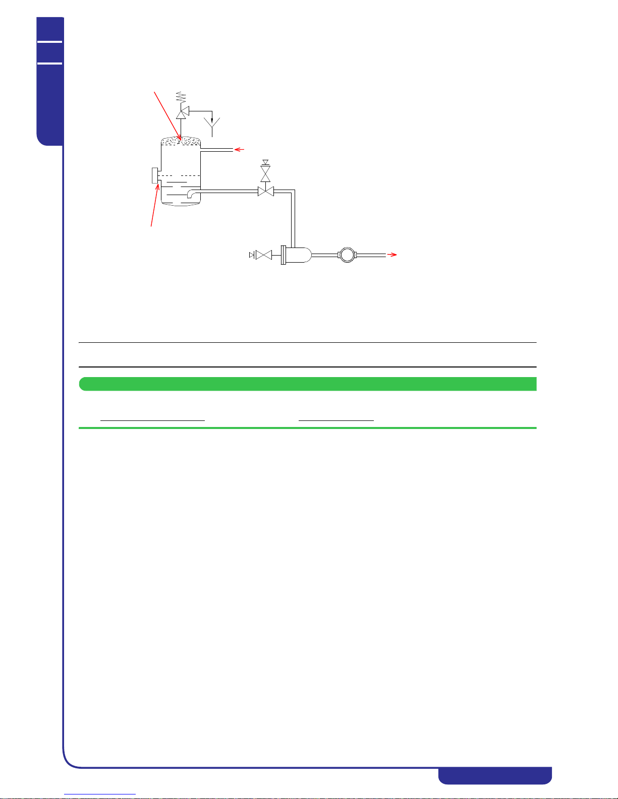
MAINTENANCE AND OPERATING MANUAL
Description
HAS T 070÷140
37
ENGLISH
EN
The data in this manual are not binding and they can be modified by the manufacturer without notice. Reproduction of this manual is strictly prohibited.
3.2.6 Liquid receiver
NOTE
SUBCOOLING: The liquid is not subcooled at the receiver outlet because of the constant presence of a small quantity of gas.
ATTENTION
LIQUID SIGHT GLASS DOWNLINE OF THE FILTER: The liquid sight glass will always show air bubbles in the liquid
flow; do not use the sight glass as a reference for refrigerant charging risk of overfilling the circuit.
3.2.7 Cycle reversal valve
The 4-way cycle reversal valve is utilised to invert the direction of flow of refrigerant fluid in order to heat or cool the
process water. This valve makes it possible to perform defrost cycles during HEAT-PUMP mode operation. The four valve
pipes are brazed to the high-low pressure sides of the compressors and exchangers (condenser and evaporator) making up the
refrigerant circuit. The spool of the main valve is shifted by a pilot solenoid valve.
4-way valve spool movement is controlled via software.
The operating principle is illustrated in the following diagrams.
The liquid receiver is installed to hold the higher volume of refrigerant present in the liquid phase when the unit is
operating in “HEAT-PUMP (WINTER)” mode. The plate evaporator (with respect to the condensing coils) offers reduced
volume when functioning as a condenser in heat pump mode. The liquid receiver is equipped with a level sight glass,
although the reading is reliable only when the unit is operating in chiller mode.
IN
UPPER AREA:
presence of gas only
level in
HEAT-PUMP mode
level in
CHILLER mode
LEVEL
SIGHT GLASS
FILTER
TO THE
THERMOSTATIC
LIQUID SIGHT-GLASS
EXPANSION VALVE

MAINTENANCE AND OPERATING MANUAL
Description
HAS T 070÷140
38
ENGLISH
EN
The data in this manual are not binding and they can be modified by the manufacturer without notice. Reproduction of this manual is strictly prohibited.
UNIT IN CHILLER MODE
UNIT IN HEAT-PUMP MODE
3.3 Hydraulic system (optional)
The units can be equipped with a hydraulic system on request. The system, which is
installed on board the unit, is composed of centrifugal pump and storage tank and
supplied with the following accessories:
• expansion vessel
• water pressure relief valve
• automatic air bleed valve
• discharge valve
• water pressure gauge at pump outlet
• electric heaters (optional).
Units can be equipped with a medium pressure head pump on request.
Pump installation is envisaged in the following configurations:
• single pump
• double pump (one in stand-by)
• pump and tank assembly
• double pump (one in stand-by) and tank unit.
4-WAY
CYCLE REVERSAL VALVE
SCHRAEDER
VALVES
COMPRESSOR/S
WATER
WATER
EVAPORATOR
Coil
Spool
FANS
THERMOSTATIC VALVE
DRAIN COCK
CHECK
VALVE
FILTER
LIQUID SIGHT-GLASS
THERMOSTATIC VALVE
LIQUID RECEIVER
SCHRAEDER
VALVE
CHECK
VALVE
Main valve
CONDENSER
Pilot valve
UNIT
INLET
OUTLET
4-WAY
CYCLE REVERSAL VALVE
SCHRAEDER
VALVES
COMPRESSOR/S
WATER
WATER
EVAPORATOR
Coil
Spool
FANS
THERMOSTATIC VALVE
DRAIN COCK
SCHRAEDER
VALVE
FILTER
LIQUID SIGHT-GLASS
THERMOSTATIC VALVE
CHECK
VALVE
CHECK
VALVE
Main valve
CONDENSER
Pilot valve
UNIT
INLET
INLET
RECEIVER

MAINTENANCE AND OPERATING MANUAL
Description
HAS T 070÷140
39
ENGLISH
EN
The data in this manual are not binding and they can be modified by the manufacturer without notice. Reproduction of this manual is strictly prohibited.
ATTENTION
The pump must never run dry.
3.4 Cabinet
The cabinet is made of galvanized panels with polyester powder coating.
3.5 Protection rating
The protection rating of the entire unit is IP54 with insulation class F to ensure it is compatible with outdoor operation in all
climates.
3.6 Electrical circuit
The electrical circuit schematic is given in the annexed diagrams.
3.7 Overall dimensions
See attachments

MAINTENANCE AND OPERATING MANUAL
Installation
HAS T 070÷140
40
ENGLISH
EN
The data in this manual are not binding and they can be modified by the manufacturer without notice. Reproduction of this manual is strictly prohibited.
CHAPTER 4
INSTALLATION
4.1 Foreword
This manual is addressed to personnel responsible for installing, using and servicing the unit.
The unit described is designated CHILLER or HEAT PUMP.
The expression “pressure” is used to indicate relative pressure.
4.2 Symbols
Symbols present on the unit and also in the dimensional drawings and refrigerant circuit diagrams.
4.3 Installation
ATTENTION
Before installing or operating these units, read the chapter concerning " Safety". The unit must be installed in
accordance with current national legislation in the country of use.
4.3.1 Inspection
As soon as the unit has been unpacked check it carefully for damage.
4.3.2 Location
1. The unit can be installed either outdoors or in an enclosed environment, depending on the degree of IP protection
of the electrical panel and the unit itself.
2. If the unit is installed indoors the place of installation must be well ventilated. In certain cases it may be necessary
to install ventilation fans or extractor fans in order to reduce room temperature.
3. The ambient air must be clean, avoid sea ambients (brackish air), and not contain flammable gas or corrosive
solvents.
4. The minimum and maximum working ambient temperature are specified on the unit data plate. Ensure that the
unit is not installed in flows of hot air emitted by other equipment.
In extremetemperature conditions, the protection devices may trip.
5. Do not obstruct or interfere with the air flow produced by the unit; comply strictly with the minimum spaces/
distances specified in the installation drawings.
6. The machine must be installed on a perfectly horizontal flat surface, built and calculated to withstand the
machine’s operating weight, especially in the contact points highlighted in the installation drawing. In the event
of installations which fail to comply with the above requirements, the manufacturer’s warranty cover will
immediately become null and void and the unit could malfunction or even lock out.
7. Leave free space around the unit for access during service interventions (see Attachments).
Unit water inlet Unit water outlet
Heat recovery exchanger or
desuperheater water inlet (models
with heat recovery exchanger or
desuperheater only)
Heat recovery exchanger or
desuperheater water outlet (models
with heat recovery exchanger or
desuperheater only)
Indication of the axis of reference for
lifting operations
Unit drain point
Electric shock hazard Flow of cooling air
Direction of flow of refrigerant fluid
Rotation direction of pump
(if present) and fans
Risk of injury due to sharp edges
Risk of burns from contact with hightemperature surfaces
Opening to use to insert bars for unit
lifting purposes
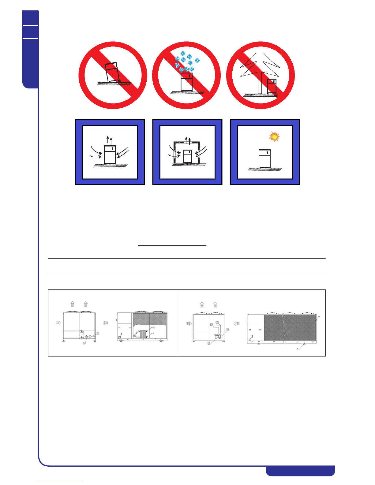
MAINTENANCE AND OPERATING MANUAL
Installation
HAS T 070÷140
41
ENGLISH
EN
The data in this manual are not binding and they can be modified by the manufacturer without notice. Reproduction of this manual is strictly prohibited.
8. Do not install the plant in sites exposed to strong winds; if unavoidable, install suitable windscreens.
4.3.3 Hydraulic connections
The unit is equipped with threaded or “Victaulic” connections (see diagram below).
1. Connect the unit to the water pipes as shown in the diagram below.
2. Provide two valves (one at the inlet, one at the outlet) to isolate the unit in the case of maintenance work without
having to empty the user water circuit.
3. If the unit is not equipped with a hydraulic unit as standard, ensure that the suction line of the pump installed
subsequently by the user is connected directly to the unit
in order to avoid excessively high pressure on the
condenser side.
NOTE
The pump must never run dry.
See point 1.

MAINTENANCE AND OPERATING MANUAL
Installation
HAS T 070÷140
42
ENGLISH
EN
The data in this manual are not binding and they can be modified by the manufacturer without notice. Reproduction of this manual is strictly prohibited.
NOTE
For correct operation of the unit install a filter to intercept debris in the water inlet pipe. Failure to observe this prescription
can result in irreparable damage to the evaporator.
In the case of plate evaporators, the clogging of even a few plates (or gaps) can cause the plate to seize (clogging), leading
to damage of part of the exchanger, even if water flow seems regular and operation is apparently normal.
The hydraulic circuit must be sized in such a way as to comply with the pressure limit value specified on the data plate and
ensure the flow rate shown in the following table is not exceeded:
Typical water side connection
1. “Victaulic” connections
2. Thermometer
3. Pressure gauge
4. Air bleed valve
5. Discharge valve
6. Anti-vibration coupling
7. Shut-off valve
8. Filter with removable filter
basket
“VICTAULIC” CONNECTION
A clamping half collars
Bseal
C weld-on stub pipe
D evaporator stub pipe
PLATE EVAPORATOR
Minimum flow rate [m
3
/h]
PLATE EVAPORATOR
Maximum flow rate [m3/h]
HAS T 070 13.0 42.1
HAS T 080 16.2 48.2
HAS T 090 18.0 52.2
HAS T 100 19.4 55.8
HAS T 110 23.0 61.9
HAS T 120 24.8 74.9
HAS T 130 27.4 81.7
HAS T 140 30.2 88.2
In
Out
1
2
3
5
6
7
8
1
2
3
4
6
7

MAINTENANCE AND OPERATING MANUAL
Installation
HAS T 070÷140
43
ENGLISH
EN
The data in this manual are not binding and they can be modified by the manufacturer without notice. Reproduction of this manual is strictly prohibited.
Evaporator pressure drops
100% recovery exchanger pressure drops
1 Has T 070
2 Has T 080
3 Has T 090
4 Has T 100
5 Has T 110
6 Has T 120
7 Has T 130
8 Has T 140
1
2
3
4
5
6
7
8
Evaporator pressure drops (kPa)
Flow rate (m3/h)
Pressure drops (kPa)
Flow rate (m3/h)
1
2
3
4
5
6
7
8
1 Has T 070
2 Has T 080
3 Has T 090
4 Has T 100
5 Has T 110
6 Has T 120
7 Has T 130
8 Has T 140

MAINTENANCE AND OPERATING MANUAL
Installation
HAS T 070÷140
44
ENGLISH
EN
The data in this manual are not binding and they can be modified by the manufacturer without notice. Reproduction of this manual is strictly prohibited.
Desuperheaters pressure drops
4.3.4 Freeze protection
Even if the minimum working ambient temperature is higher than 0 °C, during shutdown periods in the winter season the unit
may be subject to temperatures that are lower than 0 °C. In such cases if the water circuit is not drained, to avoid ice
formation ethylene or propylene glycol antifreeze should be added to the water in the following percentages:
In summer, when the unit operates as a chiller, to avoid the formation of ice ethylene or propylene glycol antifreeze should be
added to the water in the following percentages in accordance with the chilled water outlet temperature:
NOTE
With intake temperature control, the reference for the glycol percentage is equal to the setpoint less 6°C.
E.g. Setpoint 11.0 °C (reference for glycol 5 °C) recommended percentage 20%.
NOTE
- The minimum recommended antifreeze % takes the coolant's operating conditions into consideration and is not strictly
dependant on the freezing point of the chilled water leaving the unit.
- The water flow rate must comply with the value stated in the performance technical data or the selection software.
ATTENTION
Freeze protectio n setpoint set at 5°C.
For water outlet temperatures lower than 6 °C you must add a suitable quantity of antifreeze solution.
Ambient T up to [°C] Ethylene Glycol [% by weight] Propylene Glycol [% by weight]
000
-5 15 20
-10 25 30
-15 30 35
-20 40 40
water outlet T
up to [°C]
Ethylene or propylene glycol
[% by weight]
60
320
025
-5 30
-7 35
-10 40
Pressure drops (kPa)
Flow rate (m3/h)
1
2
3
4
5
6
7
1 Has T 070
2 Has T 080
3 Has T 090÷100
4 Has T 110
5 Has T 120
6 Has T 130
7 Has T 140

MAINTENANCE AND OPERATING MANUAL
Installation
HAS T 070÷140
45
ENGLISH
EN
The data in this manual are not binding and they can be modified by the manufacturer without notice. Reproduction of this manual is strictly prohibited.
4.3.5 Electrical connections
The unit's connection to the power supply must be made in compliance with laws and prescriptions in force in the place of
installation.
The voltage, frequency and number of phases must comply with the data on the unit's nameplate. The power supply voltage
must not be outside the tolerances shown on the electrical diagram, even in terms of transients. Unless otherwise specified,
the frequency tolerance is +/-1% of the nominal value (+/-2% for short periods).
With a three-phase power supply the voltage must be symmetrical (the effective values of phase to phase voltages and
consecutive phase angles must be identical). In particular, unless otherwise indicated, the maximum permissible phase
imbalance is 2%, calculated according to the formula
Vavg = average phase voltage
The line conductor and neutral conductor are not interchangeable and their positions cannot be switched.
For the electrical power supply:
1.
Connect the unit (PE terminal in the electrical cabinet) to the electrical earthing system of the building.
2.
ensure automatic interruption of the power supply in the event of an insulation fault (protection against
indirect contact in compliance with the prescriptions of IEC 60364) by means of a residual current device (the
nominal trip current of which should normally be set to 0.03 A).
3. make sure the level of protection against indirect contact at the source of the power feeding cable is equivalent at
least to IP2X or IPXXB (refer to CEI EN 60529).
4. at the start of the power cable install a device that protects it from current surges (short-circuits) (refer to the
indications given in the electrical diagram).
5. use conductors rated to carry the maximum current required at the maximum operating ambient temperature,
according to the chosen installation type (IEC 5-60364-523) (see the indications on the electrical diagram).
6. it must be installed a safety device which limits the 17 kA peak short circuit current to its own nominal cut-off
power when the short circuit current at the operation point is higher than 10 kA effective.
Indications on the electrical diagram:
• maximum permissible size of the fuse type gG.
In general, fuses can be replaced by an automatic circuit breaker set in relation to the unit's maximum current
input (consult the manufacturer if necessary)
• section and type of power cable (if not already supplied):
Installation: insulated conductors or multicore cable in an overhead or wall-mounted cable duct (type C in
compliance with IEC 5-523-60364 1983) without any other cables in contact
cable type: copper conductors, 70 °C PVC insulation (unless otherwise specified) or 90 °C EPR insulation
4.3.6 Phase Monitor
The electronic controller, with the aid of a Phase Monitor (see unit wiring diagram), enables to control unit electric power
feeding, stopping the unit in case of incorrect phase sequence or phase failure.
Tripping of the Phase Monitor stops the unit and the relative alarm is displayed.
Some measure of instability on the power feeding line can be considered to be normal.
If the frequency of unit shut-downs caused by Phase Monitor tripping should increase, contact your electricity company in
order to solve the problem.
ATTENTION
It is strictly prohibited to tamper with the Phase Monitor.
100
Vavg
Vavg respect to with voltagephase of difference Max.

MAINTENANCE AND OPERATING MANUAL
Start-up
HAS T 070÷140
46
ENGLISH
EN
The data in this manual are not binding and they can be modified by the manufacturer without notice. Reproduction of this manual is strictly prohibited.
CHAPTER 5
START-UP
ATTENTION
Before starting this type of u nit, ensure that all personnel involved have read and understood the " Safety" chapter in
this manual.
1. The unit shut-off valves must be open.
2. With a “closed” type hydraulic circuit ensure that a suitably sized expansion vessel has been installed.
3. Check that the ambient temperature is within the range indicated on the unit's data plate.
4. Check that the main switch is in the OFF position (“O”).
5. Check that the unit power supply voltage is correct.
6. Power the unit by means of the line protection device.
7.Turn the unit main switch to the ON position (“I”).
When the unit is powered the control unit display switches on. Check on the display for:
• unit alarm
• Time bands Off
• Supervision Off
• “External On/Off” Off
8.Models without pump:
before switching the unit on make sure the water pump is running and water is flowing
through the evaporator.
9. Models with discharge valves on compressors:
Check that the compressor discharge valves are open.
10. Press button for 2" to start the unit. The pump (if installed) starts immediately.
After a delay set on the electronic board the refrigerant compressor starts.
Press button again for 2" to stop the unit. The controller remains active
.
11. Compressors, pump and fans have only one correct direction of rotation.
If a SCROLL compressor does not rotate in the correct direction it will be very noisy and will be unable to
compress the refrigerant gas.
Check the direction of rotation of all components at first start and after every maintenance operation. In the event
of incorrect rotation direction of all components, invert two phase wires at the main terminals of the electrical
cabinet. In contrast, if it is found that only certain specific components are rotating in the incorrect direction, the
power feeding wires must be inverted on the individual terminals of the corresponding contactor(s) (see attached
wiring diagram).
12. If, at the time of the first start of the unit in CHILLER (SUMMER) mode the ambient temperature is high and
the temperature of water in the hydraulic circuit is significantly higher than the working value (e.g. 25-30 °C) this
means that the unit is starting in overload conditions so the protections may trip. To reduce the overload, partially
and progressively close a valve at the unit outlet to reduce the flow rate of water passing through the
evaporator. The valve can be opened fully when the water temperature in the hydraulic circuit approaches the
working value.
Similar considerations are valid with low ambient temperature and user circuit water temperature
significantly lower than the working value at the first start in HEAT-PUMP mode (“WINTER”).

MAINTENANCE AND OPERATING MANUAL
Electronic controller
HAS T 070÷140
47
ENGLISH
EN
The data in this manual are not binding and they can be modified by the manufacturer without notice. Reproduction of this manual is strictly prohibited.
CHAPTER 6
ELECTRONIC CONTROLLER
ATTENTION
This chapter provides an overview of the unit main functions. Some functions may be inactive or not present in the unit
for specific requirements. Refer to the definitive offer data.
6.1 Technical features
Management of the unit is provided by the XDRIVE ELECTRONIC CONTROLLER.
The main features of the xDRIVE controller are as follows:
Where necessary, the machine may be equipped with expansion modules to increase the number of inputs/outputs of the
electronic circuit board.
NOTE
The LEDs on the electronic controller signal the operating status of the device. Regular flashing of the yellow LED1 on the
left of the controller denotes that the device is functioning correctly.
6.1.1 Controller connectivity
The xDRIVE controller communicates with the other hardware devices in the unit (display, drivers, auxiliary modules) by
means of the CanBus port (5) or the display port (6). There are also several additional serial ports:
1. USB: used for installation and subsequent upgrading of the controller software
2. RJ-45 (Ethernet): used to connect the unit to an Ethernet network and for communication in a modular system
3. RS-485 (MODBUS): used for communication with other devices by means of the MODBUS protocol
4. RS-232 (GSM): used to connect an external modem to the controller (optional)
Power supply
12V/24V ac/dc
Digital inputs
20 optically coupled
Analog inputs
10 configurable
Analog outputs
6
Digital outputs
15
Serial outputs
1 USB
1 Ethernet
1 RS232 (optional)
1 RS485 master
1 RS485 slave
1 CAN-BUS output
Operating system
Linux
CPU
200MHz
Processor
32bit
RAM
32MB
Flash memory capacity
128MB
6

MAINTENANCE AND OPERATING MANUAL
Electronic controller
HAS T 070÷140
48
ENGLISH
EN
The data in this manual are not binding and they can be modified by the manufacturer without notice. Reproduction of this manual is strictly prohibited.
NOTE
For more details on connectivity consult the specific xCONNECT manual.
6.1.2 Display
Consultation and editing of the main operating parameters of the unit take place using the graphic display.
ATTENTION
The display is connected to the electronic controller by means of a shielded three-core cable. Consult the unit's
electrical wiring diagram to check the connection.
The main features of the display are as follows:
• 240x96 pixel resolution
• eight multifunction keys
• Front panel protection rating of IP65
• multilingual support
• buzzer
The eight multifunction keys perform different instructions in accordance with the displayed mask, improving navigation
between the various menus.
In addition to the local display mounted on the unit, it is also possible to connect a remote display to the electronic controller
(see "6.1.2.1 Remote display").
NOTE
The use of the display and the meaning of its masks are illustrated in heading "6.2 Using the display".
6.1.2.1 Remote display
The remote display is connected to the electronic controller by means of a shielded cable and it provides the facility to view
and edit the main operating parameters of the unit from a distance of 150 m.
ATTENTION
Consult the unit's electrical wiring diagram t o check connection of the remote display.
The installation procedure of a remote display is described below:
• Make the electrical connections as shown in the unit's wiring diagram
• Feed power to the unit, ensuring that
exclusively the remote display and not the local display is connected to the xDRIVE
controller
max 150mt

MAINTENANCE AND OPERATING MANUAL
Electronic controller
HAS T 070÷140
49
ENGLISH
EN
The data in this manual are not binding and they can be modified by the manufacturer without notice. Reproduction of this manual is strictly prohibited.
• Check that the following mask is shown on the display:
• Press to perform the display upload procedure
• Wait for the procedure to be completed (approximately 5 minutes)
• Check that the mask of the unit's main menu appears on the remote display (see "6.2.2 Main menu")
• Set the remote display address. To connect both displays to the electronic controller they must have different
addresses. Hold down the outermost keys on the remote display for 5 seconds:
• Enter the BIOS menu of the display by entering password 1:
• Press key 6 to open the SETTINGS menu:
• Press key 1 to open the ADR VISOGRAPH menu:
• Insert an address
other than 2 and different from the address of the local display then press SET:
• Exit the BIOS menu and connect both displays to the electronic controller.
6.1.3 Auxiliary hardware
In addition to the electronic controller and the display, the unit may incorporate the following auxiliary hardware devices:
• Driver: to control the electronic thermostatic valves (EEV)
• Auxiliary IOs: to increase the number of electronic controller inputs-outputs
Auxiliary hardware devices are present in accordance with the type of unit and they are connected on the CANbus network to
the electronic controller.
6.1.3.1 IPEX 60D (IPX 106D) and IPEX 70D (IPX 125D)
The IPEX 60D (IPX 106D) and IPEX 70D (IPX 125D) expansion modules, which are installed when necessary, make it
possible to increase the number of available I/Os in the electronic controller.
The following table lists the main features of the expansions:
IPEX 60D (IPX 106D) IPEX 70D (IPX 125D)
Digital inputs 320
Digital outputs 625
Analog inputs 710
Analog outputs 36

MAINTENANCE AND OPERATING MANUAL
Electronic controller
HAS T 070÷140
50
ENGLISH
EN
The data in this manual are not binding and they can be modified by the manufacturer without notice. Reproduction of this manual is strictly prohibited.
ATTENTION
Each auxiliary device has a CANbus address that can be set by means of the relative dip switches. Consult the electrical
wiring diagram to check addressing and the electrical connection of the auxiliary devices.
6.2 Using the display
The display makes it possible to view the status of the unit and change the main operating parameters. At the time of first
power-up the display presents a configuration menu; at the time of successive power-ups the display presents the unit's main
menu, which provides access to all the other submenus of the display.
6.2.1 First power-up
The configuration menu (wizard) provides the facility to set the main operating parameters, namely the date and time, the
display language and the temperature and pressure measurement units.
ATTENTION
The configur ation procedure may take severa l minutes, depend ing on the set paramet ers.
Do not switch off or disconnect the display during this procedure.
NOTE
The configuration menu is displayed only the first time the unit is powered up. Once the configuration procedure has been
completed the unit is ready for normal operation.
Ref. Mask Description
1/4 Used to set the unit's date and time and the date display format in the
various display masks.
Changing the date and time requires the electronic controller to be
restarted. Select and confirm to validate the changes and
restart the controller.
2/4 Used to set the language used in the display masks.
3/4 Used to select the units of measurement utilised for temperature and
pressure values between °C/bar and °F/PSI.
4/4 Used to confirm the settings made and enable normal operation of the
unit.

MAINTENANCE AND OPERATING MANUAL
Electronic controller
HAS T 070÷140
51
ENGLISH
EN
The data in this manual are not binding and they can be modified by the manufacturer without notice. Reproduction of this manual is strictly prohibited.
6.2.2 Main menu
The main menu is the most important mask of the display. In the area at the top of the screen it shows the unit inlet and outlet
water temperature and the operating mode. The area at the bottom of the screen contains a representation of the unit's circuits
and shows the operating status of the compressors. The same area shows the status of fans and the other special functions
present in the unit.
The keys at the bottom are used to gain access to the other display menus and switch the unit on/off (see "6.2.7 Keys").
6.2.3 Display menus
The submenus that can be accessed from the main menu are as follows:
I/O: displays the value of all the unit's temperature and pressure parameters and the status of all devices present (pumps,
compressors, fans, solenoid valves, see "6.3 I/O menu")
SET: display and edit the setpoints for water thermoregulation (see "6.4 Setpoints Menu")
USER: display and edit the unit's general operating parameters, namely the autostart function and the operating mode (see
"6.5 User Menu")
MENU: provides access to reserved and password-protected submenus from which all the unit's operating parameters can be
edited (see "6.7 Reserved menu")
ALARM: shows the status of active alarms in the unit (see "6.8 Alarms")
6.2.4 Powering up the unit
The unit is powered up by means of a prolonged press of the key. The icon present in all masks of the display
shows that the unit is running.
The same procedure is used to power off the unit. The icon present in all masks of the display shows that the unit is
off.
NOTE
The key is present in all di splay masks. Unit power-up and power-down can be performed using different methods
(from the supervision system, a digital input, by time bands, by remote input, and by the modularity function).
6.2.5 Power-on from a digital input
If enabled, allows the unit to be powered on/off by means of a digital input of the electronic controller.
6.2.6 Power-on by supervision system
If enabled, allows the unit to be powered on/off by means of the supervision system (see "6.7.18 Supervision").
ATTENTION
"Unit on" means that the machine can perform water temperature regulation and control the operation of all its devices
(pumps, compressors, fans and solenoid valves).

MAINTENANCE AND OPERATING MANUAL
Electronic controller
HAS T 070÷140
52
ENGLISH
EN
The data in this manual are not binding and they can be modified by the manufacturer without notice. Reproduction of this manual is strictly prohibited.
6.2.7 Keys
The following table illustrates the meaning of all the keys on the display.
NOTE
The keys appear in masks containing parameters that are repeated on more than one circuit. A prolonged press of
the key serves to view and edit the same parameters on the next ci rcuit, while a prolonged press of the key provides
the same function for the previous circuit.
Key Function
Scroll through masks
Scroll and select the fields in a mask/increase and decrease the value of a field
Scroll the parameters on different circuits (prolonged press)
Scroll the masks in the ALARM menu
Access to I/O menu (see "6.3 I/O menu")
Access to SET menu (see "6.4 Setpoints Menu")
Access to USER menu (see "6.5 User Menu")
Access to reserved menu (see "6.7 Reserved menu")
Access to ALARM menu (see "6.8 Alarms")
Unit power on/off (see "6.2.4 Powering up the unit")
Exit a menu
Activation of a field/confirmation
Alarms reset in ALARM menu (see "6.8 Alarms")
Access to EX/MD submenu from I/O menu (optional, see "6.3 I/O menu")

MAINTENANCE AND OPERATING MANUAL
Electronic controller
HAS T 070÷140
53
ENGLISH
EN
The data in this manual are not binding and they can be modified by the manufacturer without notice. Reproduction of this manual is strictly prohibited.
6.2.8 Icons
The meaning of all the icons that may be shown on the display is illustrated below.
Icon Meaning Icon Meaning
Unit off
Anti-freeze heater enabled/active
Unit on
Defrost enabled/active
Chiller mode operation
Heat recovery enabled/active
Heat pump mode operation
Low-noise enabled/active
Active alarm
Free-cooling enabled/active
Scroll compressor on/off
Modularity enabled/active
Screw compressor off
Airbatic enabled/active
Screw compressor on
Low temperature enabled/active
Reciprocating compressor off
Tandem enabled/active
Reciprocating compressor on/capacity
controlled
Neutral zone control enabled/active
(SETPOINT menu)
Fan on/off
PID control enabled/active (SETPOINT menu)
Fans speed controlled
Active alarm (ALARM menu)
Pump off
Active warning (ALARM menu)
Pump on
Communication blink
Temperature unloading on
Uneditable parameter/non-resettable alarm
High pressure unloading on circuit active
Resettable alarm (ALARM menu)
Low pressure unloading on circuit active
Minimum time intervals in progress (reserved
menu)

MAINTENANCE AND OPERATING MANUAL
Electronic controller
HAS T 070÷140
54
ENGLISH
EN
The data in this manual are not binding and they can be modified by the manufacturer without notice. Reproduction of this manual is strictly prohibited.
6.3 I/O menu
Press in the main menu to open the I/O (input-output) menu to display the temperature and pressure values and the
status of all the devices installed on the unit.
Ref. Mask
Display
conditions
Description
IO01 On unit with
modularity or
free-cooling
enabled
Display, on the master module, the average
temperature of the water in a modular system if
enabled (with modularity enabled see "6.7.17
Modularity"). Display temperature of the free-cooling
probe, if enabled (see "6.7.21 Free-cooling")
IO02 Display for each circuit of the unit, the condensing
and evaporation pressure values, the status of
compressors and fans, and unloading or heat recovery
procedures in progress.
In units with step control fans the icons
correspond to the number of active steps; in units with
speed controlled fans the percentage rpm value is
displayed (see "6.7.5 Fans").
In water-cooled units the percentage opening of the
valve on the condenser is displayed.
IO03 On units with
electronic
thermostatic
valves
Displays, for each circuit of the unit, the parameters
concerning the electronic thermostatic valve (see
"7.1 Electronic thermostatic valve (optional)")
showing the opening percentage of the valve, the inlet
temperature and suction pressure, the saturation
temperature, and superheating.
Displays the opening percentage of the second valve
for operation in heat pump mode, only if present.
IO04 Displays temperatures of the water inlet, water outlet
and tank outlet probes, if enabled.
IO05 Displays temperatures of the room probes, if enabled.
IO06 With heat
recovery probes
enabled
Displays temperatures of the heat recovery probes, if
enabled (see "6.7.7 Heat recovery").
IO07 Displays condensing pressures (HP) and evaporation
pressures (LP) of circuits 1-2.

MAINTENANCE AND OPERATING MANUAL
Electronic controller
HAS T 070÷140
55
ENGLISH
EN
The data in this manual are not binding and they can be modified by the manufacturer without notice. Reproduction of this manual is strictly prohibited.
6.3.1 EX/MD auxiliary I/Os
When expansion cards are installed, pressing the key in any mask of the I/O menu provides access to the menu for
display of auxiliary I/Os.
Auxiliary I/Os are:
• Digital I/Os on expansion modules (see "6.1.3.1 IPEX 60D (IPX 106D) and IPEX 70D (IPX 125D)")
• I/Os on external free-cooling modules (see "6.7.21 Free-cooling")
• Modular system slave unit I/O (see "6.7.17 Modularity")
• Special functions I/O (see "6.7.20 Special functions")
• Evaporator outlet water dual temperature probe
• Condenser water inlet and outlet probes
IO08 On units with
more than two
circuits
Displays condensing pressures (HP) and evaporation
pressures (LP) of circuits 3-4 (if present)
IO09 Displays the status of the refrigerant valves in the
unit's circuits.
IO10 Displays the status of the cycle inversion valves in the
unit's circuits.
IO11 Displays the status of the pumps installed in the unit
(see "6.7.14 Pumps").
The rotation type appears only when the unit is
equipped with two pumps (see "6.7.14.1 Pumps
rotation").
The residual rotation time appears only if the rotation
type between pumps is HOURS or STARTS+HOURS.
IO12 On units with
rows of fans
shared between
circuits
Displays the status of fans and the heat recovery
exchanger in units with rows of fans shared between
several circuits (see "6.7.5 Fans").
In units with step control fans the icons correspond to
the number of active steps; in units with speed
controlled fans the percentage rpm value is displayed
(see "6.7.5 Fans").
IO13 Displays the status of the unit's digital inputs and
digital outputs. The icon denotes a digital signal at
logical level 1, the icon at logical level 0.
Ref. Mask
Display
conditions
Description
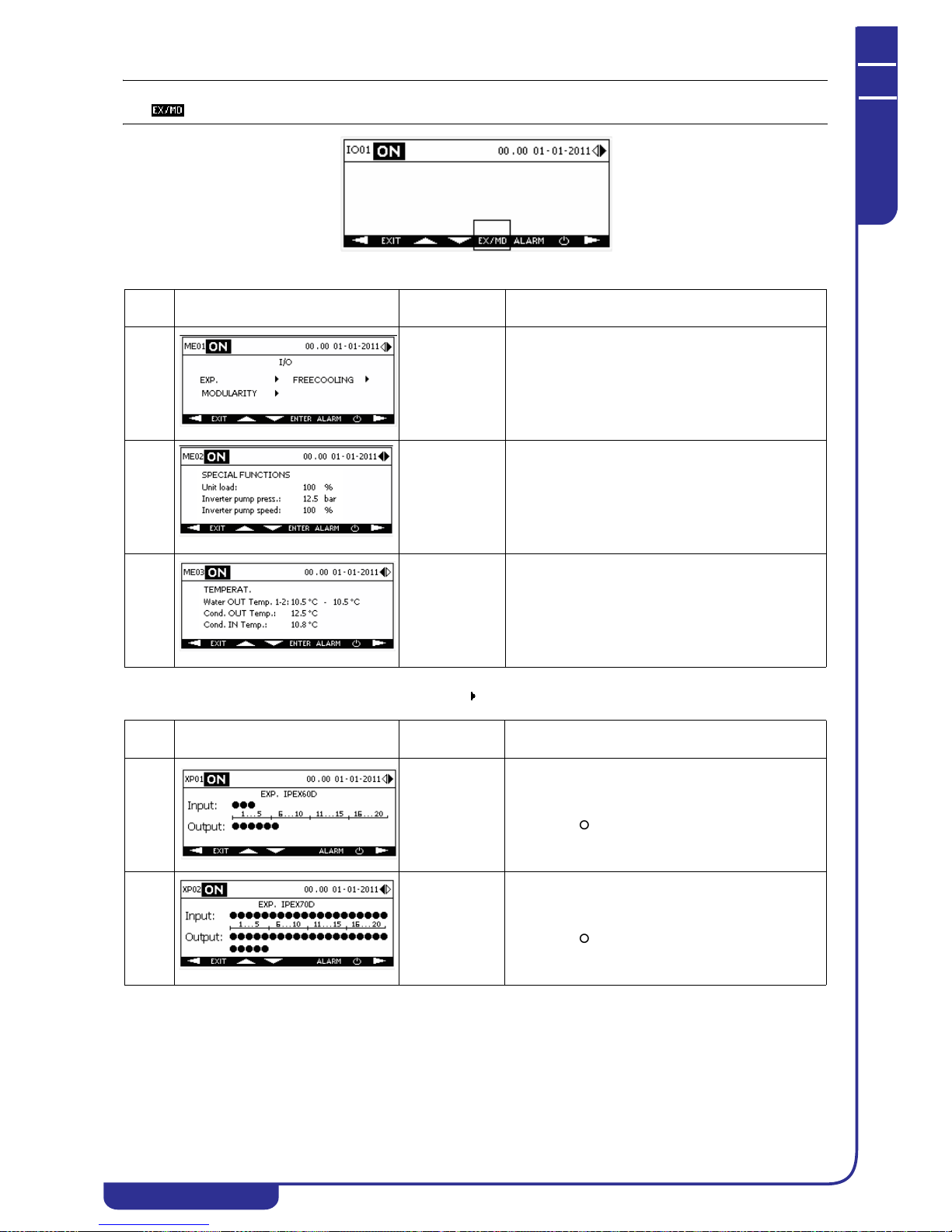
MAINTENANCE AND OPERATING MANUAL
Electronic controller
HAS T 070÷140
56
ENGLISH
EN
The data in this manual are not binding and they can be modified by the manufacturer without notice. Reproduction of this manual is strictly prohibited.
NOTE
The key appears in the I/O menu only when at last one of the previous auxiliary I/Os is present.
The XP menu is accessible from the ME menu, selecting the icon corresponding to the expansions (EXP) in mask ME01.
Ref. Mask
Display
conditions
Description
ME01 With expansion
modules present
or modularity /
free-cooling
enabled
Provides the facility to access the menu for display of
digital I/Os of the expansions, information concerning
slave modules of a modular system (see dedicated
xCONNECT manual) and free-cooling. The mask
contains the options exclusively of the functions
enabled on the unit.
ME02 With special
machine loading
functions or
inverter pump
functions
enabled
Displays the percentage of the machine load, if
enabled.
Displays pressure value and speed percentage of the
inverter pump if enabled.
ME03 With evaporator
water outlet dual
probe or
condenser probes
enabled
If the unit is equipped with two evaporator water
outlet probes, displays the temperature values. The
average value is shown in the main menu.
Displays the temperature values of the condenser
water inlet and outlet probes if present on the unit.
Ref. Mask
Display
conditions
Description
XP01 On units with
expansion
module
IPEX60D (IPX
106D) present
Displays the status of digital inputs and outputs of
expansion module IPEX60D (IPX 106D) if present on
the unit. The icon denotes a digital signal at logical
level 1, the icon at logical level 0.
XP02 On units with
expansion
module
IPEX70D (IPX
125D) present
Displays the status of digital inputs and outputs of
expansion module IPEX70D (IPX 125D) if present on
the unit. The icon denotes a digital signal at logical
level 1, the icon at logical level 0.

MAINTENANCE AND OPERATING MANUAL
Electronic controller
HAS T 070÷140
57
ENGLISH
EN
The data in this manual are not binding and they can be modified by the manufacturer without notice. Reproduction of this manual is strictly prohibited.
The IP menu is accessible from the ME menu, selecting the icon corresponding to free-cooling in mask ME01 (see
"6.7.21 Free-cooling").
The MO menu is accessible from the ME menu, selecting the icon corresponding to modularity (see "6.7.17 Modularity").
NOTE
For a description of the masks of the MO menu relative to a modular system, consult the dedicated xCONNECT manual.
6.4 Setpoints Menu
Pressing the key in the main menu provides access to the menu in which the setpoint can be edited.
The setpoint defines the reference temperature for unit thermoregulation (see "6.7.8 Regulation" ).
NOTE
Modification of the type of setpoint is possible only in the menu of the reserved menu (see "6.7.8 Regulation")
Ref. Mask
Display
conditions
Description
IF01 With free-
cooling enabled
Displays the opening percentage of the three-way
valve and the status of the free-cooling fans.
In units with step control fans the icons
correspond to the number of active steps; in units with
speed controlled fans the percentage rpm value is
displayed.
For each module, flashing of the corresponding
icon indicates correct communication between module
and unit.
Ref. Mask
Display
conditions
Description
ST01 Displays the current setpoint. Depends on the type of
setpoint programmed (see "6.7.8.1 Setpoint types" )
and the unit operating mode.
Displays the outlet water temperature in accordance
with the selected control probe (see "6.7.8
Regulation").
Displays an icon to indicate the control type, set at
either neutral zone or PID. With modularity enabled the
icon will not appear.
ST02 Makes it possible to edit the fixed setpoint for chiller
mode.
Makes it possible to edit the second setpoint for chiller
mode, (see "6.7.8.1 Setpoint types").
ST03 Makes it possible to edit the fixed setpoint for heat
pump mode.
Makes it possible to edit the second setpoint for heat
pump mode, if enabled (see "6.7.8.1 Setpoint types").

MAINTENANCE AND OPERATING MANUAL
Electronic controller
HAS T 070÷140
58
ENGLISH
EN
The data in this manual are not binding and they can be modified by the manufacturer without notice. Reproduction of this manual is strictly prohibited.
ST04 With
compensated
setpoint enabled
Makes it possible to select the room probe for
compensation (see "6.7.8.1 Setpoint types") from
among:
•BAT1
•BAT2
• Average between BAT1 and BAT2
• Minimum between BAT1 and BAT2
• Maximum between BAT1 and BAT2
Provides facility to edit maximum compensation. The
programmed value is valid for both chiller and heat
pump operating modes.
ST05 With
compensated
setpoint enabled
Facility to define the compensation setpoint and
differential for chiller mode operation (see "6.7.8.1
Setpoint types").
ST06 With
compensated
setpoint enabled
and chiller/heat
pump unit
Facility to define the compensation setpoint and
differential for heat pump mode operation (see "6.7.8.1
Setpoint types").
ST07 With time bands
setpoint enabled
Facility to set the start time of the first time band and
the relative setpoints for chiller/heat pump mode (see
"6.7.8.1 Setpoint types").
ST08 With time bands
setpoint enabled
Facility to set the start time of the second time band
and the relative setpoints for chiller/heat pump mode
(see "6.7.8.1 Setpoint types").
ST09 With time bands
setpoint enabled
Facility to set the start time of the third time band and
the relative setpoints for chiller/heat pump mode (see
"6.7.8.1 Setpoint types").
ST10 With time bands
setpoint enabled
Facility to set the start time of the fourth time band and
the relative setpoints for chiller/heat pump mode (see
"6.7.8.1 Setpoint types" ).
ST11 With adjustable
setpoint enabled
Displays the minimum setting of the adjustable setpoint
(see "6.7.8.1 Setpoint types") for chiller mode,
corresponding to a 4mA signal. Corresponds to the
fixed setpoint and editable from mask ST02.
Facility to edit the maximum setting of the adjustable
setpoint (see "6.7.8.1 Setpoint types") in chiller mode,
corresponding to a 20mA signal.
Ref. Mask
Display
conditions
Description

MAINTENANCE AND OPERATING MANUAL
Electronic controller
HAS T 070÷140
59
ENGLISH
EN
The data in this manual are not binding and they can be modified by the manufacturer without notice. Reproduction of this manual is strictly prohibited.
6.5 User Menu
Press the key in the main menu to access the menu in which you can edit the general functions of the unit: autostart,
forced enabling/disabling of special functions and personalisation of the display (language, buzzer, backlighting, contrast).
NOTE
From the USER menu you can set the unit's operating mode as chiller or heat pump.
ST12 With adjustable
setpoint enabled
Facility to edit the minimum setting of the adjustable
setpoint (see "6.7.8.1 Setpoint types") in heat pump
mode, corresponding to a 4mA signal.
Displays the maximum setting of the adjustable
setpoint (see "6.7.8.1 Setpoint types" ) for heat pump
mode, corresponding to a 20mA signal. Corresponds to
the fixed setpoint and editable from mask ST03.
Ref. Mask
Display
conditions
Description
US01 Facility to enable the autostart function (see "6.5.1
Autostart") and select the operating mode as chiller or
heat pump.
US02 With time bands
and modularity
enabled
If starting by time bands is enabled, provides facility to
force activation of the unit outside the time band (see
"6.7.16 Time bands").
If modularity is enabled, provides facility to force local
operation of a module (see specific xCONNECT
manual).
US03 With free-
cooling enabled
If free-cooling is enabled on the unit, provides facility
to disable it temporarily (see "6.7.21 Free-cooling").
US04 Facility to enable display buzzer (see "6.5.3 Buzzer").
Facility to select the language used in the display
masks (see "6.5.2 Display language").
US05 Facility to set duration of backlighting and display
contrast (see "6.5.4 Backlighting and contrast").
Ref. Mask
Display
conditions
Description

MAINTENANCE AND OPERATING MANUAL
Electronic controller
HAS T 070÷140
60
ENGLISH
EN
The data in this manual are not binding and they can be modified by the manufacturer without notice. Reproduction of this manual is strictly prohibited.
6.5.1 Autostart
The autostart function, when enabled, allows the unit to restart automatically after an electrical power loss.
6.5.2 Display language
From the USER menu you can personalise various display properties, including the language utilised in the masks (Ref.
US04), choosing from among:
• English
• Italian
•French
•German
•Spanish
• Russian
6.5.3 Buzzer
The buzzer sounds in the presence of an alarm. If the alarm suspends operation of the entire unit, the buzzer sounds
continuously; if it suspends operation of one circuit, the buzzer sounds intermittently. Activation of a warning is not
accompanied by an audible signal.
6.5.4 Backlighting and contrast
Backlighting is activated automatically when a key is pressed in order to improve visibility of the information shown on the
display. The duration of backlighting can be modified from the USER menu up to a maximum of 200s, beyond which time
the display backlighting remains on constantly (Ref. US05). In the menu also display contrast can be adjusted (Ref. US05).
6.6 Alarm Menu
With the key you can access the menu to display the alarms.
The presence of an alarm is accompanied by an audible signal, if enabled, and a digital output of the electronic controller.
The ALARM menu is structured as follows:
MANUAL RESET
The manual reset involves resetting of normal operation only following an operation on the display. An alarm message
followed by the icon denotes an alarm that cannot be reset. The icon indicates an alarm that can be reset. An alarm
is reset by selecting the relative message with the keys and pressing . You can simultaneously reset all
the alarms displayed with a single operation by a prolonged press of the key.
AUTOMATIC RESET
The automatic reset occurs for alarms that do not require manual operation on the display. If the alarm condition ceases, the
message is cleared. No padlock icon is associated with automatic reset alarms.
ALARMS COUNTER
For alarms with which this facility is associated, at the end of the display line the number of times the alarm has tripped in the
past 24 hours of operation is shown.
Alarm:
Resettable
Non-resettable
Alarm
Alarm type:
Warning
Alarm description
Number of active alarms
Number of times the alarm
in past 24 hours
Warning
Warning message that does not involve any shut-downs.
Alarm
Alarm message. Critical stop of the unit or of one of the circuits. Alarms can be manual reset or automatic reset type.
situation has recurred

MAINTENANCE AND OPERATING MANUAL
Electronic controller
HAS T 070÷140
61
ENGLISH
EN
The data in this manual are not binding and they can be modified by the manufacturer without notice. Reproduction of this manual is strictly prohibited.
6.7 Reserved menu
From the main menu, pressing the key provides access to the selection for editing of all the operating parameters.
This section is password protected.
The system envisages access with three different passwords corresponding to three authorisation levels:
• Manufacturer: access to all parameters
• Service: access to most parameters
• User: access to a limited number of parameters
It may occur that an entire menu or certain parameters are not accessible with the password that has been entered. When a
parameter cannot be edited the icon appears alongside it.
The default User password is 10 and it can be edited from the display (see menu "6.7.22 Other settings"). The passwords for
the Service and Manufacturer levels cannot be edited and they are different for each individual unit.
Certain configuration parameters (unit type, refrigerant type, fans type, etc.) cannot be edited irrespective of the password
level. Since these are essential parameters for definition of the type of unit to be controlled, they can be altered only by
downloading a new set of maps and parameters to the electronic controller.
6.7.1 Reserved menu icons
Icon Code Menu Icon Code Menu
CU Unit configuration AL Alarms configuration
CO Compressors control HM Log data
VT Fans control PM Pumps control
CD Condenser solenoid valve OR
Date/time, time bands, low-
noise
AN Anti-freeze MD Modularity
RC Recovery SU Supervision
DR
Electronic thermostatic
valves management
UN Unloading
RG
Temperature control
management
FS Special functions
DF Defrost FC Free-cooling
OL Operating hours AL Other settings
FM Manual operation

MAINTENANCE AND OPERATING MANUAL
Electronic controller
HAS T 070÷140
62
ENGLISH
EN
The data in this manual are not binding and they can be modified by the manufacturer without notice. Reproduction of this manual is strictly prohibited.
6.7.2 Access to menu functions
CU01÷CU08
Configuration
CO01÷CO10
Compressors
VT01÷VT10
Fans
AN01÷AN02
Anti-freeze
MENU
RC01÷RC03
DR01÷DR09
RG01÷RG06
DF01÷DF05
OL01÷OL12
FM01÷FM09
AL01
HM01
PM01÷PM02
OR01÷OR08
MD01÷MD07
SU01÷SU01
UN01÷UN05
FS01÷FS02
FC01÷FC07
AI01÷AI10
AA01÷AA04
AP01÷AP03
AH01÷AH08
AT01÷AT12
IP01÷IP02
PH01
MB01÷MB02
SM01
EM01
TD01÷TD02
AB01÷AB02
CA01÷CA04
BO01
LT01÷LT05
PI01÷PI03
RP01÷RP02
Heat recovery
Electronic thermostatic valves
Regulation
Defrost
Operating hours
Manual procedure
Alarms
Temperature alarms
Pressure alarms
Other alarms
History
Alarms log
Power alarms log
Pumps
Date/time
Modularity
Supervisions
Network parameters
ModBus parameters
SMS
Unloading
Special functions
Tandem
Airbatic
Auxiliary contact
Boiler
Low temperature
Inverter pump
Recovery pump
Free-cooling
Other settings
E-mail
CD01÷CD04
Condenser solenoid valve

MAINTENANCE AND OPERATING MANUAL
Electronic controller
HAS T 070÷140
63
ENGLISH
EN
The data in this manual are not binding and they can be modified by the manufacturer without notice. Reproduction of this manual is strictly prohibited.
NOTE
The reserved menu submenus are described below. Access to each submenu depends on the level of the password utilised.
6.7.3 Configuration
The menu provides the facility to display the main features of the unit.
NOTE
The icon indicates a parameter that ca nnot be edited from the disp lay.
The configuration menu masks provide the facility to display the following information:
• range, model and version of unit
•type if refrigerant used
• presence of storage tank
• fans type and layout
• type of cycle inversion on unit, if refrigerant side or water side (water-water units)
• pumps present in unit and enabling of pump(s) in anti-freeze mode
• enabling of anti-freeze heater.
• heat recovery (if present) and enabling of pump-down function at compressors starting and stopping (service
level only) specifying whether to activate function always or only during chiller mode operation.
• enabling of defrost, free-cooling type, enabling display of electronic
thermostatic valves (if present) EEV for
operation in chiller and heat pump mode.
• enabling of modularity, enabling of supervision and active supervision (service level only), enabling of
special functions and access to SPECIAL FUNCTIONS menu (Ref. FS01-FS02) (manufacturer level only).
• enabling of unit remote start (in chiller/heat pump mode) by means of digital input
• procedure for default parameters installation. The installation of default values is possible only with the unit in
status.
Consult the following headings for more details on the functions described.
6.7.4 Compressors
The main operating parameters of the unit's compressors can be set up in the menu.
NOTE
The menu is accessible via the service level password.
The masks of the unit compressors menu offer the facility to:
• disable each circuit present in the unit
• display, for each of the unit's compressors, a code that identifies the type and disable operation of an
individual compressor
•set up the rotation logic and type of balancing of the compressors and the circuits.
•set up the compressors starting time lag at the time of unit power-up
•set up the minimum running time and the stopped time of each compressor
• set up the time lags between consecutive starts of the same compressor and the delay between starts and
stops of different compressors.
• set up the time lag between starts of compressors during the defrost cycle
Modification of minimum compressor times is possible in status and only if the minimum compressor times are
terminated. With minimum times in progress, the icon is shown in the mask.
6.7.4.1 Pump-down
You can set one or more of the following pump-down types:
• at start-up, the refrigerant solenoid valve opens and the first compressor in a circuit starts when evaporation
pressure exceeds a programmed setting
• at shut-down, the refrigerant solenoid valve closes and the last compressor in a circuit stops when evaporation
pressure falls below a programmed setting
NOTE
In the event of an incorrect pump-down procedure an alarm appears on the display and will be reset automatically at the
time of the next correct start-up/shut-down.
6.7.4.2 Disabling circuits and compressors
You can disable a circuit or an individual compressor from the display when it is necessary to control the capacity of the
unit or a circuit in order to reduce the cooling capacity.
6.7.4.3 Rotating circuits and compressors
One of the following logic types can be set up:
• Compressors rotation logic: Fixed - FIFO - Balancing
• Circuits rotation logic: Fixed - FIFO - Balancing - Saturation
p
p

MAINTENANCE AND OPERATING MANUAL
Electronic controller
HAS T 070÷140
64
ENGLISH
EN
The data in this manual are not binding and they can be modified by the manufacturer without notice. Reproduction of this manual is strictly prohibited.
• Balancing type: By starts - By hours
Fixed rotation means that the unit's resources are activated without any form of rotation logic. In FIFO rotation the resources
are deactivated starting from the first one to be activated. Balancing rotation envisages the facility to set the type of balancing
between hours or starts.
The combination of the values set in the rotation parameters results in the following operation types.
Circuits rotation
Fixed FIFO Balancing Saturation
Compressors rotation
Fixed
Power-up: the first compressor of
the first circuit is started and then,
in sequence, all the other
compressors of the same circuit.
Thereafter the compressors of the
other circuits are started with the
same logic, in sequence, up to the
last circuit.
Power-up: the first
compressor of the first circuit
is started and then all the
other compressors of the same
circuit. Thereafter the
compressors of the other
circuits are started with the
same logic, in sequence, up to
the last circuit.
Power-up: the first compressor
of the circuit having the
compressor with the smallest
number of hours/starts in
absolute, and thereafter, in
sequence, the other compressors
of the same circuit. Thereafter,
the compressors of the other
circuits are started in
accordance with the same logic.
Power-up: the first compressor of
the circuit having the compressor
with the smallest number of hours/
starts in absolute is started, and
thereafter, in sequence, all the
other compressors of the same
circuit. Thereafter, the
compressors of the other circuits
are started in accordance with the
same logic.
Power-down: the last compressor
of the last circuit is stopped,
followed by all the other
compressors of the same circuit, in
reverse sequence. Thereafter the
compressors of the other circuits
are stopped with the same logic, in
sequence, up to the first circuit.
Power-down: the last
compressor of the first circuit
is stopped, followed by all the
other compressors of the same
circuit, in reverse sequence.
Thereafter the compressors of
the other circuits are stopped
with the same logic, in
sequence, up to the last
circuit.
Power-down: the last
compressor of the circuit
having the compressor with the
largest number of hours/starts
in absolute is stopped, and
thereafter, in sequence, all the
other compressors of the same
circuit. Thereafter, the
compressors of the other
circuits are stopped in
accordance with the same logic.
Power-down: the first compressor
of the circuit having the
compressor with the largest
number of hours/starts in absolute
is stopped, and thereafter, in
sequence, all the other
compressors of the same circuit.
Thereafter, the compressors of the
other circuits are stopped in
accordance with the same logic.
FIFO
Power-up: the first compressor of
the first circuit is started and then
all the other compressors of the
same circuit. Thereafter the
compressors of the other circuits
are started with the same logic, in
sequence, up to the last circuit.
Power-up: the first
compressor of the first circuit
is started and then all the
other compressors of the same
circuit. Thereafter the
compressors of the other
circuits are started with the
same logic, in sequence, up to
the last circuit.
Power-up: the first compressor
of the circuit having the
compressor with the smallest
number of hours/starts in
absolute is started, and
thereafter, in sequence, all the
other compressors of the same
circuit. Thereafter, the
compressors of the other
circuits are started in
accordance with the same logic.
Power-up: the first compressor of
the circuit having the compressor
with the smallest number of hours/
starts in absolute is started, and
thereafter, in sequence, all the
other compressors of the same
circuit. Thereafter, the
compressors of the other circuits
are started in accordance with the
same logic.
Power-down: the first compressor
of the last circuit is stopped and
then all the other compressors of
the same circuit. Thereafter the
compressors of the other circuits
are stopped in accordance with the
same logic, in sequence, up to the
first circuit.
Power-down: the first
compressor of the first circuit
is stopped and then all the
other compressors of the same
circuit. Thereafter the
compressors of the other
circuits are stopped in
accordance with the same
logic, in sequence, up to the
last circuit.
Power-down: the first
compressor of the circuit
having the compressor with the
largest number of hours/starts
in absolute is stopped, and
thereafter, in sequence, all the
other compressors of the same
circuit. Thereafter, the
compressors of the other
circuits are stopped in
accordance with the same logic.
Power-down: the first compressor
of the circuit having the
compressor with the largest
number of hours/starts in absolute
is stopped, and thereafter, in
sequence, all the other
compressors of the same circuit.
Thereafter, the compressors of the
other circuits are stopped in
accordance with the same logic.
Balancing
Power-up: the compressor with the
smallest number of hours/starts of
the first circuit is started followed
by all the other compressors of the
same circuit, in accordance with
the same logic. Thereafter, the
compressors of the other circuits
are started in accordance with the
same logic.
Power-up: the compressor
with the smallest number of
hours/starts of the first circuit
is started followed by all the
other compressors of the same
circuit, in accordance with the
same logic. Thereafter, the
compressors of the other
circuits are started in
accordance with the same
logic.
Power-up: the compressor with
the smallest number of hours/
starts in absolute is started,
followed by the compressor
with the smallest number of
hours/starts of another circuit,
and so forth. Two compressors
of the same circuit are never
started consecutively.
Power-up: the compressor with the
smallest number of hours/starts in
absolute is started, and then the
next compressor with the smallest
number of hours/starts in the same
circuit. Thereafter, the
compressors of the other circuits
are started in accordance with the
same logic.
Power-down: the compressor with
the largest number of hours/starts
of the last circuit is stopped
followed by all the other
compressors of the same circuit, in
accordance with the same logic.
Thereafter the compressors of the
other circuits are stopped with the
same logic, in reverse sequence, up
to the first circuit.
Power-down: the compressor
with the largest number of
hours/starts of the first circuit
is stopped followed by all the
other compressors of the same
circuit, in accordance with the
same logic. Thereafter the
compressors of the other
circuits are stopped with the
same logic, in reverse
sequence, up to the first one.
Power-down: the compressor
with the smallest number of
hours/starts in absolute is
stopped, followed by the
compressor with the largest
number of hours/starts of
another circuit, and so forth.
Two compressors of the same
circuit are never stopped
consecutively.
Power-down: the compressor with
the largest number of hours/starts
in absolute is stopped, and then the
next compressor with the largest
number of hours/starts in the same
circuit. Thereafter, the
compressors of the other circuits
are stopped in accordance with the
same logic.
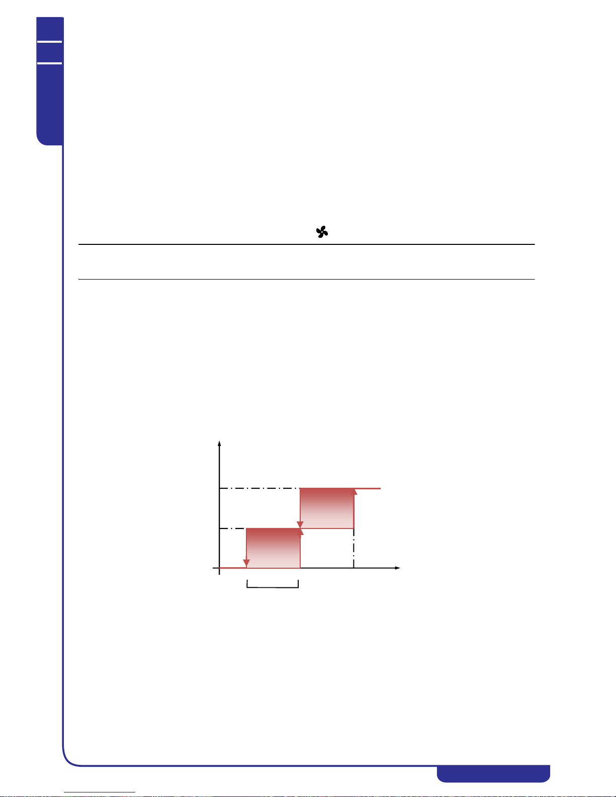
MAINTENANCE AND OPERATING MANUAL
Electronic controller
HAS T 070÷140
65
ENGLISH
EN
The data in this manual are not binding and they can be modified by the manufacturer without notice. Reproduction of this manual is strictly prohibited.
6.7.4.4 Minimum times
In order to maintain correct operation of the unit-s compressors, times for compressor starting and stopping must be
observed. Compressor times, which can be modified from the display, are as follows:
• Compressors starting t ime lag at the time of unit start-up: this is the time lag between the time of start-up
of the unit and starting of the first compressor
• Minimum ON time: minimum operating time that each compressor must comply with;
• Minimum OFF time: minimum stopped time that each compressor must comply with;
• Same compressor starts tim e: minimum time that must elapse between consecutive starts of the same
compressor;
• Start times between different compressors: minimum time that must elapse between starts of two different
compressors;
• Stopping times between different compressors: minimum time that must elapse between stopping of two
different compressors;
• Starts time between compressors in defrost: minimum time that must elapse between starts of two different
compressors during the defrost cycle (see "6.7.9 Defrost").
6.7.5 Fans
The parameters for control of the unit's fans can be set up in the menu.
NOTE
The menu is accessible via the service level password. The types of fans present in the unit are shown in the configuration
menu.
The fans menu masks provide the facility to display the following information for each circuit:
• operating parameters step controlled fans
• operating parameters step controlled fans with low-noise
• operating parameters speed controlled fans
• operating parameters speed controlled fans with low-noise
6.7.5.1 Low Noise
You can program different setpoints for low noise operation in order to reduce noise emissions of the system during the night
time.
The settings of the fans for operation in low-noise mode are utilised also for defrost mode.
6.7.5.2 Fans step control
Involves activation of a series of steps of fans in accordance with the reference condensing pressure value.
The activation logic of the steps in chiller mode is shown in the following diagram:
Chiller
Step
Set 1
Set 2
Pressure
DIFF
Set - DIFF
Step 1
Step 2

MAINTENANCE AND OPERATING MANUAL
Electronic controller
HAS T 070÷140
66
ENGLISH
EN
The data in this manual are not binding and they can be modified by the manufacturer without notice. Reproduction of this manual is strictly prohibited.
The activation logic of the steps in heat pump mode is shown in the following diagram:
Heat pump
In addition, for heat pump mode, operation of the fans can be forced to constantly on.
6.7.5.3 Fans speed control
This control type makes it possible to increase/decrease ventilation intensity in a linear manner in accordance with the
reference condensing pressure.
The ventilation intensity in chiller mode is shown in the following diagram and is linked to the starting of at least one
compressor in the reference circuit:
Chiller
The ventilation intensity in heat pump mode is shown in the following diagram and is linked to the starting of at least one
compressor in the reference circuit:
Heat pump
Step
Set 1
Pressure
DIFF
Set + DIFF
Set 2
Step 1
Step 2
%
Set 1
DIFF 1
DIFF 3
DIFF 2
Set 2
Set 2 LN
Press.
DIFF 3
DIFF 3
Perc. 2=Perc. 3
Perc.
Perc. 1
2 LN
Pressione
DIFF 3
DIFF 3
DIFF 1
Set 1
DIFF 2
Set 2
Set 2 LN
Perc. 1
Perc.
2 LN
Perc. 2=Perc. 3
%
DIFF 3

MAINTENANCE AND OPERATING MANUAL
Electronic controller
HAS T 070÷140
67
ENGLISH
EN
The data in this manual are not binding and they can be modified by the manufacturer without notice. Reproduction of this manual is strictly prohibited.
6.7.6 Anti-freeze
In the menu you can set the parameters for operation of the anti-freeze heater and the pump in anti-freeze mode.
NOTE
The menu is accessible by means of the service level password and with the anti-freeze heater or anti-freeze pump enabled.
The masks of the anti-freeze menu offer the facility to:
• set the reference probe, the setpoint and the differential for activation of the anti-freeze heater
• set the reference probe, the setpoint and the differential for activation of the anti-freeze pump
6.7.6.1 Anti-freeze heater
Activation of the anti-freeze heater prevents the formation of ice in the evaporator. If the selected reference temperature is
lower than the programmed setpoint, the heater is activated. The heater is switched off if the temperature becomes higher
than setpoint + differential, in accordance with the following diagram:
The reference probe can be selected from among the following:
•BEWIT
•BEWOT
•BTWOT
•BAT1
•BAT2
• average among BATs
• lower among BATs
•BEWOT1
•BEWOT2
• lower among BEWOTs
NOTE
A probe can be selected only if it is effectively present in the unit.
The anti-freeze heater is enabled from the display, by accessing the CONFIGURATION menu with the manufacturer level
password. Enabling can be one of three alternative types:
• always
• only with compressors stopped (both for thermoregulation and for unit power-off)
• only with unit running (both with compressors running or stopped due to thermoregulation).
The icon in the main mask indicates that the anti-freeze heater is enabled in the unit. The icon changes to if the
heater is on.
6.7.6.2 Anti-freeze pumps
The pumps in the unit can be started in anti-freeze mode to prevent the formation of ice in the unit's hydraulic circuit. If the
unit is stopped and the selected reference temperature is lower than the programmed setpoint, one of the pumps is started.
The pump is switched off if the temperature becomes higher than setpoint + differential, in accordance with the following
diagram:

MAINTENANCE AND OPERATING MANUAL
Electronic controller
HAS T 070÷140
68
ENGLISH
EN
The data in this manual are not binding and they can be modified by the manufacturer without notice. Reproduction of this manual is strictly prohibited.
The reference probe can be selected from among the following:
•BEWIT
•BEWOT
•BTWOT
•BAT1
•BAT2
• average of BATs
•lower of BATs
•BEWOT1
•BEWOT2
• lower of BEWOTs
NOTE
A probe can be selected only if it is effectively present in the unit.
The pump activated in anti-freeze mode depends on the type of pumps operation programmed (see "6.7.14 Pumps").
If the free-cooling function is enabled on the unit (see "6.7.21 Free-cooling"), to prevent the formation of ice also in the freecooling section, activation of the anti-freeze pump is accompanied by complete opening of the three-way free-cooling valve.
Operation of the pumps in anti-freeze mode is enabled by accessing the CONFIGURATION menu with the service level
password.
6.7.7 Heat recovery
The parameters for control of the heat recovery function can be set up in the menu.
Heat recovery makes it possible to use the condensing gas to heat domestic hot water during operation of the unit in chiller
mode.
NOTE
The menu is accessible by means of the service level password and with the heat recovery function enabled.
The masks of the heat recovery menu offer the facility to:
• set up the heat recovery type, the heat recovery control type and the setpoint for reactivation following
unloading of the heat recovery function
• set the reference probe, the setpoin t and the differential for activation of the heat recovery function in
temperature mode
• set the minimum recovery off and on times and the interval between two recovery procedures. Set the
time lags for management of the by-pass (see "6.7.7.2 Recovery operating logic")
6.7.7.1 Heat recovery types
You can set one of the following heat recovery types:
•Total
• Partial - separate
• Partial - single
For each of the three types heat recovery can be controlled in two different ways:
• By digital inputs
• By temperature (with probe installed and enabled)
The combination of the two previous parameters defines one of the following operating types:
Recovery type
Total Partial-Separate Partial-Single
Recovery control
From digital inputs
A single digital input of the
electronic controller activates the
recovery request on all the unit's
circuits.
Each digital input of the electronic
controller corresponds to one of
the unit's circuits. Activation of a
digital input activates the heat
recovery request of a single
circuit.
Each digital input of the electronic
controller corresponds to a heat
recovery request. Activation of a
digital input activates the heat
recovery request on the first available
circuit (with at least one compressor
running).
By Temperature
If the reference temperature is
below setpoint-differential the
heat recovery request is activated
on all the unit's circuits. The
request terminates if the
temperature is above the setpoint.
Recovery is activated on a number
of circuits that is proportional to
the reference temperature within
the interval between setpointdifferential and setpoint.
Recovery is activated on a number of
circuits that is proportional to the
reference temperature within the
interval between setpoint-differential
and setpoint. Recovery is activated
only on available circuits (with at least
one compressor running).

MAINTENANCE AND OPERATING MANUAL
Electronic controller
HAS T 070÷140
69
ENGLISH
EN
The data in this manual are not binding and they can be modified by the manufacturer without notice. Reproduction of this manual is strictly prohibited.
In control by temperature it is possible to select the reference probe from between:
• BRWOT (if present)
• BRWIT (if present)
6.7.7.2 Recovery operating logic
The heat recovery activation logic on a circuit is illustrated in the following diagram:
By-pass activation means capacity control of the circuit during recovery activation and deactivation stages. Capacity control
occurs with stopping of a compressor in the circuit. The duration of capacity control is imposed by the sum of times T1+T2
(see diagram).
Specifically:
T1 = recovery activation time lag
T2= by-pass deactivation time lag
Activation of heat recovery means opening of the solenoid valve to transfer the flow of superheated refrigerant from the
condenser to the recovery exchanger.
Heat recovery complies with the minimum On and Off times and the interval between consecutive recovery procedures set on
the display.
NOTE
During heat recovery the fans of the circuit in question are switched off. If two circuits share the same row of fans, the fans
are switched off only if heat recovery is in progress on both the circuits in question.
The recovery request can be managed in relation to the temperature detected by the probe located on the heat recovery
exchangers. This mode can be activated only in the presence of "Total" or "Partial single" recovery. The following diagram
describes the control logic of a machine with 4 recovery exchangers:
RECOVERY REQUEST
RECOVERY ON
RECOVERY ON
T1 T2 T1 T2 T1 T2
MINIMUM RECOVERY TIME MINIMUM RECOVERY OFF TIME
MINIMUM TIME BETWEEN TWO RECOVERY CYCLES
RECOVERY REQUEST
RECOVERY
INLET
BY-PASS
ACTIVATION
RECOVERY
OUTLET
Set
Diff
Set-Diff
Temp.
Compressor
status
Step 4 On
Step 3 On
Step 2 On
Step 1 On
Steps Off

MAINTENANCE AND OPERATING MANUAL
Electronic controller
HAS T 070÷140
70
ENGLISH
EN
The data in this manual are not binding and they can be modified by the manufacturer without notice. Reproduction of this manual is strictly prohibited.
6.7.7.3 Unloading and recovery
If, during recovery, the condensing pressure in the circuit reaches the unloading threshold, recovery is deactivated and the
circuit is set to unloading mode. Recovery can restart after the pressure has fallen to below a programmed reactivation after
unloading value.
The icon in the main menu indicates the presence of the heat recovery function on the unit. During heat recovery, the
icon becomes key .
6.7.8 Regulation
The parameters for control of the unit's temperature regulation operation can be set up in the menu.
The masks of the regulation menu offer the facility to:
• define the setpoint type and the reference probe for regulation
• define the reference probe for regulation in heat pump mode
• define the regulation type as neutral zone or PID, and the regulation band for operation in chiller and
heat pump mode
• define parameters KI, KD, Wind-up and sampling time for PID regulation
• define the compressors start time lags in and outside the neutral zone and the time lag between
compressor stops outside the neutral zone
6.7.8.1 Setpoint types
You can set one of the following setpoint types on the display:
•Fixed
• Double
• Compensated
• By time band
• Adjustable
FIXED SETPOINT
• A fixed setpoint value can be defined for operation in chiller mode and for operation in heat pump mode.
DOUBLE SETPOINT
• You can define two different setpoint values on the display and switch between them by means of a digital
input.
• For operation in heat pump mode you can set a further two different setpoint values and switch between them
with the same digital input as that of chiller mode.
COMPENSATED SETPOINT
• The setpoint is variable and it is calculated in accordance with a reference room temperature in accordance
with the following diagram:
The reference setpoint is the chiller or heat pump fixed setpoint depending on the unit's operating mode.
Compensated setpoint
Reference
Maximum
Compensation
Compensation
Reference room
Heat Pump
Chiller
compensation
setpoint
differential
setpoint
temperature

MAINTENANCE AND OPERATING MANUAL
Electronic controller
HAS T 070÷140
71
ENGLISH
EN
The data in this manual are not binding and they can be modified by the manufacturer without notice. Reproduction of this manual is strictly prohibited.
If a negative compensation differential is defined, the compensated setpoint diagram is as follows:
SETPOINT BY TIME BAND
• You can define four different time bands, each of which corresponding to a fixed setpoint. When the current
time is within a time band, the corresponding setpoint is applied. The ending time of each hourly time band
corresponds to the starting time of the next band.
ADJUSTABLE SETPOINT
• The setpoint is variable and it is calculated in accordance with an analog input signal of the 4...20 mA type, in
accordance with the following diagram:
In chiller mode, the chiller fixed setpoint corresponds to a 4mA input signal, while the maximum chiller setpoint, editable
from the display, corresponds to a 20mA input signal.
In heat pump mode, the heat pump fixed setpoint corresponds to a 4mA input signal, while a 20mA input signal corresponds
to the maximum heat pump setpoint editable on the display.
6.7.8.2 Regulation types (PID - neutral zone)
There are two regulation types settable on the display:
•PID
• Neutral zone
PD REGULATION
In PID regulation the reference temperature is controlled by means of a proportional + integral + derivative action in
accordance with PID regulation logic. Regulation therefore depends on the contribution of three parameters:
KP: proportional coefficient. This is the value of the regulation band, i.e. the deviation with respect to the setpoint.
Increasing this value reduces the error at steady state operation, but it makes the system less stable;
KI: integral coefficient. This is the time in which the temperature remains stable. The contribution of this coefficient cancels
the error at steady state conditions but tends to make the system less stable (Re. RG04);
Reference room
Compensation
Chiller
Compensated setpoint
Reference
Maximum
Compensation
compensation
setpoint
differential
setpoint
temperature
Heat pump
Maximum setpoint
Chiller setpoint
Minimum setpoint
Heat pump
Chiller
4mA
20mA
Analog input 4-20mA
setpoint
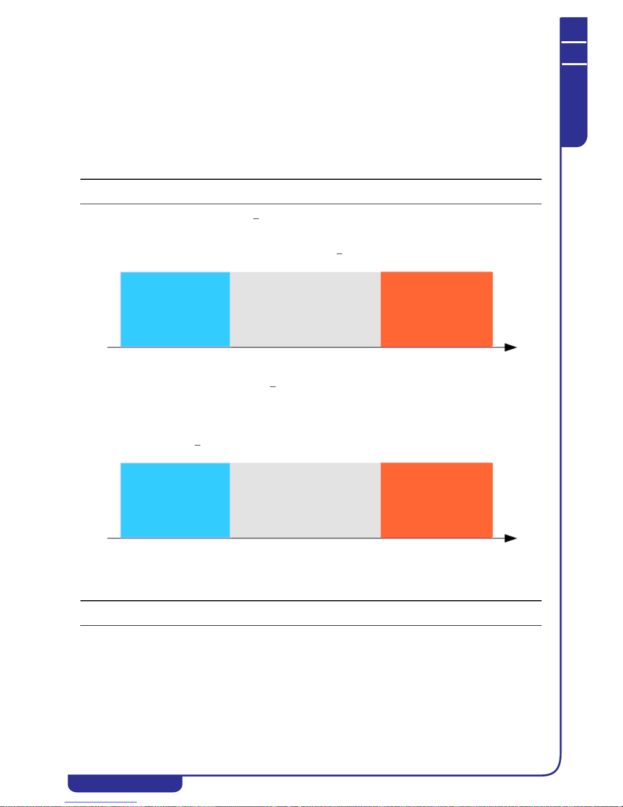
MAINTENANCE AND OPERATING MANUAL
Electronic controller
HAS T 070÷140
72
ENGLISH
EN
The data in this manual are not binding and they can be modified by the manufacturer without notice. Reproduction of this manual is strictly prohibited.
KD: derivative coefficient. This is the rate of temperature variation. The contribution of this coefficient increases damping
and stability of the system.
Coefficient KI acts on the regulation only when the reference temperature is within the Wind-up band. The KD coefficient
influences regulation at intervals corresponding to the sampling time.
The sum of contributions of the three parameters generates a regulation variable in relation to which the unit's compressors
are stopped and started.
NEUTRAL ZONE REGULATION
In neutral zone regulation the unit's compressors are started and stopped in accordance with the setpoint and the regulation
band or differential observing the reference time intervals.
NOTE
Neutral zone means the deviation between the setpoint and the regulation band width.
In chiller mode, if the reference temperature is > Setpoint+Diff, the unit's compressors are started in sequence, in compliance
with the starting time lag outside neutral zone. If the reference temperature is within the neutral zone, the unit's compressors
are started in sequence in compliance with the starting time lag in the neutral zone. Starts occur only if at least one of the
unit's compressors is already running. If the reference temperature is
< Setpoint, the unit's compressors are stopped in
sequence, in compliance with the stopping time lag outside neutral zone.
In heat pump mode, if the reference temperature is > Setpoint-Diff, the unit's compressors are started in sequence, in
compliance with the starting time lag outside neutral zone.
If the reference temperature is within the neutral zone, the unit's compressors are started in sequence in compliance with the
starting time lag in the neutral zone. Starts occur only if at least one of the unit's compressors is already running.
If the reference temperature is
< Setpoint, the unit's compressors are stopped in sequence, in compliance with the stopping
time lag outside neutral zone.
6.7.9 Defrost
NOTE
The menu is accessible by means of the service level password and with defrost enabled.
During operation in heat pump mode, the unit's condensing coils function as evaporators so there is a risk of their surfaces
icing up. The defrost procedure makes it possible to avoid ice formation on the coils by inverting the operating cycle of the
unit for a defined time interval.
In the DEFROST menu you can define the parameters for control of the procedure, notably the defrost type which can be
chosen from:
• Independent: in defrost conditions each circuit activates the procedure irrespective of the status of the other
circuits;
• Sepa rate: in defrost conditions each circuit checks the status of the other circuits and waits for the termination
of any defrost procedures in progress before starting its own defrost cycle;
The unit can manage a maximum number of defrost cycles per hour which, if exceeded, generates a warning on the
display.
Reduction
Cooling capacity
Neutral
Increase
Cooling capacity
Set
Set+Diff
Temperature
Zone
Reduction
Cooling capacity
Neutral
Increase
Cooling capacity
Set-Diff
Set Temperature
Zone

MAINTENANCE AND OPERATING MANUAL
Electronic controller
HAS T 070÷140
73
ENGLISH
EN
The data in this manual are not binding and they can be modified by the manufacturer without notice. Reproduction of this manual is strictly prohibited.
6.7.9.1 Defrost conditions
The formation of ice on a coil causes a reduction of efficiency of the corresponding circuit. This can be detected by an
excessive increase in the maximum difference of real temperature MTDR compared to the target temperature MTDI or an
excessive lowering of the evaporation pressure.
From the display you can select the real MTD coefficient calculation probe of each circuit and the setting for the condition:
MTDR >
MTDI + SET
which, if true, starts the defrost procedure after an activation time lag.
The procedure is activated also in the event in which evaporation pressure of the circuit is below a setpoint defined after an
activation time lag. The condition is false if the pressure becomes greater than setpoint+diff.
6.7.9.2 Defrost procedure
If one of the two defrost conditions is confirmed on a circuit, the following procedure is activated:
1. Inversion of cycle valve: the compressors react in accordance with the cycle valve inversion type defined. Valve
inversion is carried out after a time lag;
2. Activation of all compressors of the circuit after a time lag. The compressors are started, one after the other, with
a parametrizable time interval, and the relative fans are started for a time having the same duration as the defrost
procedure.
3. Dripping: the compressors behave in accordance with the programmed type of valve inversion and the cycle valve
is inverted after the same time lag as in the first stage. After the cycle inversion, a dripping time is observed
before the end of the defrost procedure.
During the defrost cycle the fans are started after a time lag with respect to starting of the compressors, and they are
controlled in accordance with the settings of the low-noise procedure for chiller operation.
The period of exclusion is the minimum time that must elapse between two defrost procedures on the same circuit. The same
time is observed at each fresh activation of the circuit. The defrost procedure performed in accordance with the pressure
value does not observe the exclusion time.
The cycle valve inversion type can be:
• OFF COMP.: the compressors are all off during valve inversion;
• COMP. REG.: the compressors maintain their status during valve inversion;
• CIRC. CAP. CNTRL..: if completely activated, the circuit capacity is reduced by decreasing the number of
active compressors, during valve inversion.
6.7.10 Operating hours
The menu shows the operating hours and the number of starts of the unit's main devices. If the operating hours of a
device exceed the threshold set for maintenance, a warning is shown on the display.
NOTE
The menu is accessible only via the service level password.
Exclusively for compressors, the following information is calculated and shown on the display:
• Number of starts of each compressor
• Maximum number of starts per hour for each compressor
• Average number of starts per hour for each compressor
• Minimum number of starts per hour for each compressor
NOTE
The recorded information can be reset from the display.
6.7.11 Manual procedure
In the menu the system provides the facility to force activation of certain devices of the unit in order to check their
behaviour at the time of maintenance or testing.
NOTE
The menu is accessible only via the service level password.
The manual procedure can be enabled only if the unit is in OFF status.
The devices that can be controlled in this mode are the following:
•Pumps
• Anti-freeze heater
• Compressors

MAINTENANCE AND OPERATING MANUAL
Electronic controller
HAS T 070÷140
74
ENGLISH
EN
The data in this manual are not binding and they can be modified by the manufacturer without notice. Reproduction of this manual is strictly prohibited.
• Cycle inversion valves/water-side 3-way cycle inversion valves
• Fans (step or speed controlled)
• Free-cooling (3-way valves, fans)
NOTE
During the manual procedures the alarms are always enabled.
6.7.12 Alarms set
The unit's alarm settings can be edited in the menu.
NOTE
The menu is accessible only via the service level password.
The following operations are possible from the alarms set menu:
• define the setpoints and trip delays of the high and low temperature alarms for all the probes enabled on the
unit
• define the setpoints, differentials, and trip delays of the high and low pressure alarms for all the transducers
present on the unit
• disable the low pressure alarm during the defrost procedure
• change the settings for the water differential, tank level, phase monitor, and compressor oil level alarms, if
enabled
6.7.13 Log
The menu contains records of the operating parameters, saved at the time of tripping of an alarm.
The information is recorded in the two following logs:
• Alarms log
•Power log
6.7.13.1 Alarms log
The information in the log is as follows:
• Date and time of the alarm
• Description and code of the alarm
• Temperature/pressure readings of all enabled probes
• Status of unit's solenoid valves
6.7.13.2 Power log
In the presence of a power alarm (phase-monitor) the system records the date/time of alarm tripping and reset.
NOTE
The log files can be reset by accessing the menu using the manufacturer or service level password, when the unit is off.
6.7.14 Pumps
The parameters for management of the pumps can be defined in the menu.
NOTE
The menu is accessible exclusively by means of the service level password and with at least one pump installed in the unit.
The masks of the pumps menu offer the facility to:
• set the time lag between stopping of a pump and shut-down of the unit
• set the rotation interval between pumps and the duration of simultaneous operation
• set the pumps rotation interval (with time rotation enabled)
• set the operating pump (with manual rotation enabled)
The number of pumps present in the unit is shown in the configuration menu.
When the unit is powered up the enabled pump is started. When the unit is shut down, the pump continues to run for a time
period settable on the display.
6.7.14.1 Pumps rotation
The pumps rotation logic is as follows:
• Manual: the pump to be started can be selected on the display
• By starts: at each unit start-up a different pump is started with respect to the pump that was running at the last
shut-down
• By time: after exceeding a preset number of operating hours of a pump, the other pump starts running
• By starts and time: combination of the above two logics
In the event of an overload alarm on the pump that is currently running, the other pump cuts in automatically.
The active pump is stopped after the unit is shut down with a parametrized delay which, in the case of an alarm, is not
observed.

MAINTENANCE AND OPERATING MANUAL
Electronic controller
HAS T 070÷140
75
ENGLISH
EN
The data in this manual are not binding and they can be modified by the manufacturer without notice. Reproduction of this manual is strictly prohibited.
6.7.15 Date/time
The system date and time can be set and time band operation can be configured in the menu.
NOTE
The menu is accessible only with the unit in OFF status.
ATTENTION
The unit must be restarted by means of the key which appears in the menu, to confirm the entered data.
6.7.16 Time bands
The starting/stopping of the unit can be managed in accordance with the current time and date. One of the following
operating bands can be set up:
1. Hourly band. This mode allows the start time and end time of the band to be defined, so that the unit can be
started only when the current time is within the band. If the time set as the end of the band is before the time set as
the start of the band, the time band will terminate on the day after the current day.
2. Weekly band. Provides the facility to set a day of the week for the start and one for the end of the operating band,
allowing the unit to be started only when the current date is within the band. If used in combination with the
hourly time band, the weekly band can be of two types:
• From date to date: the unit is active from the starting time of the time band starting date until the ending hour
of the band ending date
• Day by day: from the starting day of the band to the ending day of the band the unit is active each day from the
starting time to the ending time
3. Deactivation bands. Two deactivation bands can be enabled to manage shut-down periods (e.g. holidays,
weekends). Within each period, defined by a starting date and month and an ending date and month, the unit
remains off.
With hourly band, weekly band or deactivation band enabled, a holding setpoint can be programmed. In this manner, in
chiller mode, if the regulation temperature increases beyond the set value, the unit is restarted even outside the bands.
In heat pump mode the unit is started if the temperature falls below the holding setting.
6.7.17 Modularity
The parameters for configuration of a modular system can be defined in the menu.
NOTE
The menu is accessible by means of the service level password and with modularity enabled. Modularity can be enabled in
the configuration menu. For more information on modular systems, refer to the xCONNECT connectivity manual.
A modular system is composed of a master module which regulates and monitors correct operation of the entire system, and
a series of slave modules. The maximum number of modules permissible within a modular system is 10.
The connection between modules is created with an Ethernet network as shown in the following diagram:

MAINTENANCE AND OPERATING MANUAL
Electronic controller
HAS T 070÷140
76
ENGLISH
EN
The data in this manual are not binding and they can be modified by the manufacturer without notice. Reproduction of this manual is strictly prohibited.
NOTE
The modules are interconnected by way of a switch that allows the system to be connected to a LAN network if required.
6.7.17.1 Back-up module
In a modular system one unit can be defined as the back-up module. In this manner, one of the units configured is considered
as a redundant (spare) unit, and it is started in the case of one of the other units or due to programmed rotation of the units in
the network.
Rotation of the units occurs after a programmable time in hours and it involves first the complete shut-down of the unit that
must be replaced and then start-up of the unit that was previously in stand-by status.
6.7.17.2 Overboost
The overboost function involves activation of the unit in stand-by in addition to all the other units in situations when the
regulation temperature is too far from the setpoint.
6.7.18 Supervision
Supervision services (ModBus, Ethernet, SMS, Email) can be configured in the menu.
NOTE
The menu is accessible with supervision enabled. Enabling of supervision is possible in the configuration menu (see "6.7.18
Supervision"). For more information on modular systems, refer to the xCONNECT connectivity manual.
6.7.19 Unloading
The parameters for management of unloading can be defined in the menu.
NOTE
The menu is accessible only via the service level password.
The function makes it possible to reduce the unit's cooling capacity when required; it can concern the entire unit or a single
circuit and it occurs by stopping or reducing the capacity of one or more compressors. Unloading types are as follows:
• Unloading by high t emperature: can be enabled - on the unit:
Having defined an unloading setpoint and differential, if the temperature reading of the probe remains above
the setpoint for an activation time interval, one compressor in each circuit is stopped or its capacity is
controlled, depending on the type of compressor. If the temperature of the probe is lower than or equal to the
unloading setpoint minus the differential, or if its maximum duration has elapsed, the unloading function is
deactivated and the compressors are restarted.
• Unloading by low temperature : can be enabled (heat pump only) - on the unit:
Having defined an unloading setpoint and differential, if the temperature reading of the probe remains below
the setpoint for an activation time interval, one compressor in each circuit is stopped or its capacity is
controlled, depending on the type of compressor. If the temperature of the probe becomes higher than or equal
to the unloading setpoint plus the differential, or if its maximum duration has elapsed, the unloading function
is deactivated and the compressors are restarted.
• Unloading by high pressure : always present - on the circuits:
Having defined an unloading setpoint, differential and time, if the condensing pressure measured on one
circuit is higher than or equal to the setpoint, the unloading function is activated on the circuit and therefore
one compressor is stopped or its capacity is controlled, depending on the type of compressor exclusively on
the circuit in question.
The unloading function is deactivated only if the condensing pressure falls below and remains below the
unloading setpoint for a preset time or if it falls below setpoint - diff.
• Unloading by high pressure in heat pump: can be enabled - on the circuits
Having defined an unloading setpoint, differential and time, if the condensing pressure measured on one
circuit is higher than or equal to the setpoint, the unloading function is activated on the circuit and therefore
one compressor is stopped or its capacity is controlled, depending on the type of compressor exclusively on
the circuit in question.
The unloading function is deactivated only if the condensing pressure falls below and remains below the
unloading setpoint for a preset time or if it falls below setpoint - diff.
• Unloading by low pressure : always present - on the circuits:
Having defined an unloading setpoint, differential and time, if the evaporation pressure measured on one
circuit is lower than or equal to the setpoint, the unloading function is activated on the circuit and therefore
one compressor is stopped or its capacity is controlled, depending on the type of compressor exclusively on
the circuit in question.
The unloading function is deactivated only if the condensing pressure rises and remains above the unloading
setpoint for a preset time or if it rises above setpoint + diff.
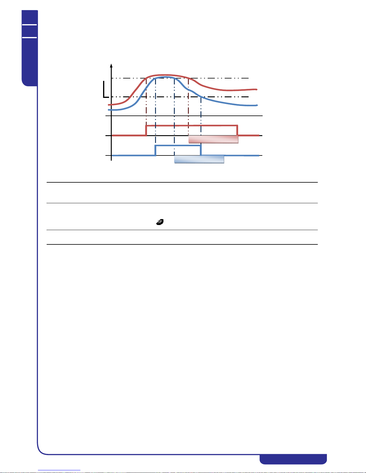
MAINTENANCE AND OPERATING MANUAL
Electronic controller
HAS T 070÷140
77
ENGLISH
EN
The data in this manual are not binding and they can be modified by the manufacturer without notice. Reproduction of this manual is strictly prohibited.
The following diagram describes:
• Line A: High pressure unloading with stop due to setpoint-differential
• Line B: High pressure unloading with stop due to time
NOTE
If the unloading condition is no longer true, when the compressor restarts the compressors minimum time intervals are
observed.
6.7.20 Special functions
The unit's special functions can be defined in the menu.
NOTE
The menu is accessible only with special functions enabled.
The special functions are described below.
6.7.20.1 Airbatic
The Airbatic function can be enabled at the time of unit configuration and only in air-water units.
The function controls a solenoid valve, which is activated if:
1. All the circuits on the unit have reached 100% of their cooling capacity
2. At least one of the condensing pressure values of the circuits in the unit has reached a programmed setpoint value
3. The average temperature of the room probes has reached a programmed setpoint value
4. The average temperature of the thermoregulation probe has reached a programmed setpoint value.
The solenoid valve is managed with minimum activation and deactivation times.
6.7.20.5 Boiler
The Boiler function is enabled from the display of chiller + heat pump units, and it consists in the facility, during operation in
heat pump mode, to switch on one or more remote heaters or a water boiler to integrate/replace the unit. The two operating
modes configurable from the display are described below.
• Integrated control:
The Boiler function is activated when the average temperature of the room probes is below a programmed
setpoint and if the temperature of the thermoregulation probe is below another programmed setpoint. In this
case, the heaters or boiler are switched on and they remain on until room temperature increases to above the
setpoint plus a differential value. During activation of the function the unit continues to perform its normal
thermoregulation functions.
• Separate control:
The Boiler function is activated when the average temperature of the room probes is below a programmed
setpoint and if the temperature of the thermoregulation probe is below another programmed setpoint. In this
case, the heaters or boiler are switched on and they remain on until room temperature increases to above the
setpoint plus a differential. During activation of the function the unit suspends its normal thermoregulation
functions.
B
A
A
B
Unloading time
Unloading time
Pressure
Set
Diff

MAINTENANCE AND OPERATING MANUAL
Electronic controller
HAS T 070÷140
78
ENGLISH
EN
The data in this manual are not binding and they can be modified by the manufacturer without notice. Reproduction of this manual is strictly prohibited.
6.7.20.6 Remote control
The special remote control function is enabled from the display and it provides the facility to perform thermoregulation in
accordance with an external analog signal. The unit's compressors are started in a proportional manner with respect to the
value of said signal, while rotations and activation times of the compressors continue to be observed. The analog input signal
must be of the 0..10V type.
6.7.20.7 Alarm contact
The special alarm contact function can be enabled from the display and it makes it possible to use an auxiliary digital output
of the electronic controller to signal a series of alarms or warnings. The digital output functions in a manner that is
independent from the standard alarm relay. The alarms and warnings that must be signalled by the digital output can be
selected on the display from the following groups:
• compressor alarms
• unit/pumps/compressors operating hours warning
• fans overload alarms
• phase-monitor alarm
• pumps overload alarm
• tank/differential pressure switch (not present)/flow switch alarms
• electronic thermostatic valves alarms
• unloading active
• defrost active
• overboost active
• faulty or open circuit probes alarms
• high/low temperatures/pressures alarms
• anti-freeze pump/heater
6.7.20.8 Unit load
The special unit load function can be enabled from the display and it makes it possible to set an 0...10V analog output of the
electronic controller to indicate the percentage of the unit's cooling capacity. A signal of 0V indicates zero cooling capacity,
while 10V indicated maximum cooling capacity.
6.7.20.9 Inverter pump
The special inverter pump function can be enabled at the time of configuration. An analog output of the electronic controller
detects the outlet pressure of a pump, which is then controlled by means of an inversely proportional PID regulation. The
speed of the pump decreases if the pressure rises and increases if the pressure falls. The analog input for pressure reading is
configurable between 4..20mA and 0..5V, the analog output for speed control is 0..10V.
6.7.20.10 Disabling of circuits from digital inputs
The special function is enabled from the display and, by way of the digital inputs of the electronic controller it makes it
possible to control the capacity of the unit. Each circuit of the unit has a corresponding digital input that makes it possible to
enable/disable the circuit completely.
6.7.20.11 Low temperature
The special low temperature function is enabled from the display and it makes it possible to edit several parameters during
low temperature operation. If the regulation temperature is lower, for a preset time, than a programmed setpoint, the values of
the following parameters are replaced with the values relative to low temperature operation:
• High pressure alarm setpoint and differential
• High pressure unloading activation setpoint
• High superheating setpoint
• PID parameters and dead zone of the solenoid valves PID control.
Modification of the parameters occurs irrespective of the unit status (On, Off, alarm, etc.) while the parameter values for
normal operation are restored if the temperature rises above the activation setpoint.
6.7.20.12 Pumps for heat recovery/desuperheaters
The special function is enabled in the configuration stage and it makes it possible to control operation of one/two pumps
dedicated to heat recovery/desuperheaters. Operation of the pumps is identical to that of the unit's pumps and therefore it is
possible to program pumps rotation logic and a time lag at the time of unit shut-down.
In the presence of heat recovery, you can select on the display whether to start the pump only during the recovery demand,
with relative shut-down time lag, or always, so that the pump is always running when desuperheaters are present.
The system envisages pump overload alarms monitoring that is identical to the system used for the unit's main pumps.

MAINTENANCE AND OPERATING MANUAL
Electronic controller
HAS T 070÷140
79
ENGLISH
EN
The data in this manual are not binding and they can be modified by the manufacturer without notice. Reproduction of this manual is strictly prohibited.
6.7.21 Free-cooling
The parameters for management of Free-Cooling can be defined in the menu.
The free-cooling unit is modular. One or more external free-cooling modules can be added in communication with the
machine.
NOTE
The menu is accessible by means of the service level password and with Free-cooling enabled.
Free-cooling provides the facility to exploit ambient temperature, whenever possible, to cool the process water. By means of
a modulating three-way valve the water is transferred to a fan coil and cooled in a manner that is independent of or in
addition to normal operation of the unit.
The function is activated when the following condition is fulfilled for a programmable time period (minutes):
BAT < BFCIT
where:
• BAT is the temperature of the reference ambient probe
• BFCIT is the water temperature at the free-cooling coil inlet
• is the free-cooling activation differential
If the previous condition is false for a programmable time, free-cooling is deactivated.
Free-cooling can be activated only during operation of the unit in chiller mode.
The envisaged mode applicable on the machine is modular.
6.7.21.1 Modular free-cooling
Modular free-cooling can be implemented with a system of free-cooling units, each of which composed of a valve and a
group of fans. The maximum number of modules that can be connected to the unit is 6.
CONFIGURATION
Proceed as follows to configure a modular free-cooling system.
1. Enable free-cooling in mask CU05 of the menu selecting the MODULAR option (changes can only be made
after accessing the reserved menu using either the service or manufacturer level password);
Chiller
Free-Cooling Module
RS485 ModBus RTU
Free-Cooling Module
Free-Cooling Module
Free-Cooling Module
Free-Cooling Module

MAINTENANCE AND OPERATING MANUAL
Electronic controller
HAS T 070÷140
80
ENGLISH
EN
The data in this manual are not binding and they can be modified by the manufacturer without notice. Reproduction of this manual is strictly prohibited.
2. Open the free-cooling menu and set up the parameters for communication with free-cooling modules in mask
FC04, specifying the number of modules connected, the Modbus communication utilised, and the Modbus
addresses of the modules;
3. In mask FC05, specify the type of fans installed in the connected free-cooling modules and the number of steps, in
the presence of step-controlled fans;
4. Set up the configuration parameters on the free-cooling modules electronic controller (see specific manual).
NOTE
Correct communication between the unit and the external free-cooling modules is indicated in mask IF01 in the I/O menu
(see "6.3.1 EX/MD auxiliary I/Os" .
6.7.22 Other settings
The following operations can be performed in the menu:
• change user password
• define an offset on all the unit's temperature and pressure probes
• display enabled probes and their measurement range
6.8 Alarms
An alarm situation is signalled in the unit by means of an audible signal (buzzer) and the appearance of the relative message
in the display ALARM menu. Depending on the alarm type, the system either suspends operation of a circuit, of a single
device, or of the entire unit.
6.8.1 Buzzer
In the case of an alarm, the display activates the buzzer continuously if the alarm concerns the entire unit, or intermittently if
it concerns a single circuit.
The buzzer can be enabled from the display in the USER menu.
6.8.2 Alarms list
The following list shows the possible alarms that may be tripped on the unit:
Alarm
code
Alarm description Controller action Operation Reset
Active
in OFF
Notes
A001 Unit maintenance Warning on
display
Immediate Auto No If operating hours > defined
setting
A002 Pump 1 overload Unit OFF/Pump 2
ON if enabled
Immediate Man. No Digital input
A003 Pump 1 maintenance Warning on
display
Immediate Auto No If operating hours > defined
setting
A004 Pump 2 overload Pump 1 On if
enabled/Unit Off
Immediate Man. No Digital input
A005 Pump 2 maintenance Warning on
display
Immediate Auto No If operating hours > defined
setting
A006 -- -- -- -- -- -A007 Tank level Unit Off Delayed Man.
/Del.
No Digital input

MAINTENANCE AND OPERATING MANUAL
Electronic controller
HAS T 070÷140
81
ENGLISH
EN
The data in this manual are not binding and they can be modified by the manufacturer without notice. Reproduction of this manual is strictly prohibited.
A008 Water differential pressure
switch (***)
Unit Off Immediate Man. No Digital input
A009 Phase-monitor Unit Off Immediate Man.
/Del.
Yes Digital input. With phase-
monitor enabled
A010 Probe(s) not enabled Warning on
display
Immediate Auto Yes If non-enabled probe is
selected
A011 Evaporator water IN high
temperature
* Delayed Man. No With probe enabled
A012 Evaporator water IN low
temperature
Warning on
display
Delayed Auto No With probe enabled
A013 Evaporator water OUT high
temperature
* Delayed Auto No With probe enabled
A014 Evaporator water OUT low
temperature (**)
Unit Off except
for Pumps
Immediate Auto Yes With probe enabled.
Activation Setpoint,
Deactivation Setpoint+Diff
A015 Probe BAT1 faulty or open
circuit
Unit Off except
for Pumps
Delayed Auto Yes With probe enabled
A016 Probe BAT2 faulty or open
circuit
Unit Off except
for Pumps
Delayed Auto Yes With probe enabled
A017 Probe BEWIT faulty or open
circuit
Unit Off except
for Pumps
Delayed Auto Yes With probe enabled
A018 Probe BEWOT faulty or open
circuit
Unit Off except
for Pumps
Delayed Auto Yes With probe enabled
A019 Tank water OUT high
temperature
Delayed Auto Yes With probe enabled
A020 Tank water OUT low
temperature
Unit Off except
for Pumps
Delayed Auto Yes With probe enabled
A021 Probe BTWOT faulty or open
circuit
Unit Off except
for Pumps
Delayed Auto Yes With probe enabled
A022 Probe BRWIT faulty or open
circuit
Unit Off except
for Pumps
Delayed Auto Yes With probe enabled
A023 Probe BRWOT faulty or open
circuit
Unit Off except
for Pumps
Delayed Auto Yes With probe enabled
A024 Module 2 not connected to
network
Warning on
display
Immediate Auto Yes With modularity enabled. Only
on master module
A025 Alarm present on module 2 Warning on
display
Immediate Auto Yes With modularity enabled. Only
on master module
A026 Module 3 not connected to
network
Warning on
display
Immediate Auto Yes With modularity enabled. Only
on master module
A027 Alarm present on module 3 Warning on
display
Immediate Auto Yes With modularity enabled. Only
on master module
A028 Module 4 not connected to
network
Warning on
display
Immediate Auto Yes With modularity enabled. Only
on master module
A029 Alarm present on module 4 Warning on
display
Immediate Auto Yes With modularity enabled. Only
on master module
A030 Module 5 not connected to
network
Warning on
display
Immediate Auto Yes With modularity enabled. Only
on master module
A031 Alarm present on module 5 Warning on
display
Immediate Auto Yes With modularity enabled. Only
on master module
A032 Module 6 not connected to
network
Warning on
display
Immediate Auto Yes With modularity enabled. Only
on master module
A033 Alarm present on module 6 Warning on
display
Immediate Auto Yes With modularity enabled. Only
on master module
Alarm
code
Alarm description Controller action Operation Reset
Active
in OFF
Notes

MAINTENANCE AND OPERATING MANUAL
Electronic controller
HAS T 070÷140
82
ENGLISH
EN
The data in this manual are not binding and they can be modified by the manufacturer without notice. Reproduction of this manual is strictly prohibited.
A034 Module 7 not connected to
network
Warning on
display
Immediate Auto Yes With modularity enabled. Only
on master module
A035 Alarm present on module 7 Warning on
display
Immediate Auto Yes With modularity enabled. Only
on master module
A036 Module 8 not connected to
network
Warning on
display
Immediate Auto Yes With modularity enabled. Only
on master module
A037 Alarm present on module 8 Warning on
display
Immediate Auto Yes With modularity enabled. Only
on master module
A038 Module 9 not connected to
network
Warning on
display
Immediate Auto Yes With modularity enabled. Only
on master module
A039 Alarm present on module 9 Warning on
display
Immediate Auto Yes With modularity enabled. Only
on master module
A040 Module 10 not connected to
network
Warning on
display
Immediate Auto Yes With modularity enabled. Only
on master module
A041 Alarm present on module 10 Warning on
display
Immediate Auto Yes With modularity enabled. Only
on master module
A042 Master module cannot be
reached
Warning on
display
Immediate Auto Yes With modularity enabled. Only
on slave module
A043 Circuit 1 high pressure switch Circuit Off Immediate Man. Yes Digital input
A044 Circuit 1 high pressure Circuit Off + Man. Yes Analog input
A045 Circuit 1 low pressure Circuit Off Immediate Man. No Analog input
A046 Transducer -BHP1 faulty or
open circuit
Circuit Off Immediate Man. Yes Analog input
A047 Transducer -BLP1 faulty or
open circuit
Circuit Off Delayed Man. Yes Analog input
A048 -- -- -- -- -- -A049 Max. number of defrost cycles
reached on circuit 1
Warning on
display
Immediate Auto No With defrost enabled
A050 Incorrect circuit 1 starting
pump-down
Warning on
display
Immediate Auto No With starting pump-down
enabled
A051 Circuit 1 off incorrect pump-
down
Warning on
display
Immediate Auto No With stopping pump-down
enabled
A052 Compressor 1 circuit 1
overload
Circuit Off Immediate Man. No Digital input
A053 Compressor 1 circuit 1 internal
alarm
Circuit Off Immediate Man. No
A054 Compressor 1 circuit 1
maintenance
Warning on
display
Immediate Auto No If operating hours > defined
setting
A055 Compressor 1 circuit 1 oil level Circuit Off Immediate Man. No
A056 Compressor 1 circuit 1 start
error
Compressor off Delayed Man. No
A057 Compressor 2 circuit 1
overload
Circuit Off Immediate Man. No Digital input
A058 Compressor 2 circuit 1 internal
alarm
Circuit Off Immediate Man. No
A059 Compressor 2 circuit 1
maintenance
Warning on
display
Immediate Auto No If operating hours > defined
setting
A060 Compressor 2 circuit 1 oil level Circuit Off Immediate Man. No
A061 Compressor 2 circuit 1 start
error
Compressor off Delayed Man. No
A062 Compressor 3 circuit 1
overload
Circuit Off Immediate Man. No Digital input
Alarm
code
Alarm description Controller action Operation Reset
Active
in OFF
Notes

MAINTENANCE AND OPERATING MANUAL
Electronic controller
HAS T 070÷140
83
ENGLISH
EN
The data in this manual are not binding and they can be modified by the manufacturer without notice. Reproduction of this manual is strictly prohibited.
A063 Compressor 3 circuit 1 internal
alarm
Circuit Off Immediate Man. No
A064 Compressor 3 circuit 1
maintenance
Warning on
display
Immediate Auto No If operating hours > defined
setting
A065 Compressor 3 circuit 1 oil level Circuit Off Immediate Man. No
A066 Compressor 3 circuit 1 start
error
Compressor off Delayed Man. No
A067 Compressor 4 circuit 1
overload
Circuit Off Immediate Man. No
A068 Compressor 4 circuit 1 internal
alarm
Circuit Off Immediate Man. No
A069 Compressor 4 circuit 1
maintenance
Warning on
display
Immediate Auto No
A070 Compressor 4 circuit 1 oil level Circuit Off Immediate Man. No
A071 Compressor 4 circuit 1 start
error
Compressor off Delayed Man. No
A072 Circuit 2 high pressure switch Circuit Off Immediate Man. Yes If operating hours > defined
setting
A073 Circuit 2 high pressure Circuit Off Immediate Man. Yes Analog input
A074 Circuit 2 low pressure Circuit Off + Man. No Analog input
A075 Transducer -BHP2 faulty or
open circuit
Circuit Off Immediate Man. Yes Analog input
A076 Transducer -BLP2 faulty or
open circuit
Circuit Off Delayed Man. Yes Analog input
A077 -- -- -- -- -- -A078 Max. number of defrost cycles
reached on circuit 2
Warning on
display
Immediate Auto No With defrost enabled
A079 Incorrect circuit 2 starting
pump-down
Warning on
display
Immediate Auto No With starting pump-down
enabled
A080 Circuit 2 off incorrect pump-
down
Warning on
display
Immediate Auto No With stopping pump-down
enabled
A081 Compressor 1 circuit 2
overload
Circuit Off Immediate Man. No Digital input
A082 Compressor 1 circuit 2 internal
alarm
Circuit Off Immediate Man. No
A083 Compressor 1 circuit 2
maintenance
Warning on
display
Immediate Auto No If operating hours > defined
setting
A084 Compressor 1 circuit 2 oil level Circuit Off Immediate Man. No
A085 Compressor 1 circuit 2 start
error
Compressor off Delayed Man. No
A086 Compressor 2 circuit 2
overload
Circuit Off Immediate Man. No Digital input
A087 Compressor 2 circuit 2 internal
alarm
Circuit Off Immediate Man. No
A088 Compressor 2 circuit 2
maintenance
Warning on
display
Immediate Auto No If operating hours > defined
setting
A089 Compressor 2 circuit 2 oil level Circuit Off Immediate Man. No
A090 Compressor 2 circuit 2 start
error
Compressor off Delayed Man. No
A091 Compressor 3 circuit 2
overload
Circuit Off Immediate Man. No Digital input
A092 Compressor 3 circuit 2 internal
alarm
Circuit Off Immediate Man. No
Alarm
code
Alarm description Controller action Operation Reset
Active
in OFF
Notes

MAINTENANCE AND OPERATING MANUAL
Electronic controller
HAS T 070÷140
84
ENGLISH
EN
The data in this manual are not binding and they can be modified by the manufacturer without notice. Reproduction of this manual is strictly prohibited.
A093 Compressor 3 circuit 2
maintenance
Warning on
display
Immediate Auto No If operating hours > defined
setting
A094 Compressor 3 circuit 2 oil level Circuit Off Immediate Man. No
A095 Compressor 3 circuit 2 start
error
Compressor off Delayed Man. No
A096 Compressor 4 circuit 2
overload
Circuit Off Immediate Man. No
A097 Compressor 4 circuit 2 internal
alarm
Circuit Off Immediate Man. No
A098 Compressor 4 circuit 2
maintenance
Warning on
display
Immediate Auto No
A099 Compressor 4 circuit 2 oil level Circuit Off Immediate Man. No
A100 Compressor 4 circuit 2 start
error
Compressor off Delayed Man. No
A101 Circuit 3 high pressure switch Circuit Off Immediate Man. Yes Digital input
A102 Circuit 3 high pressure Circuit Off Immediate Man. Yes Analog input
A103 Circuit 3 low pressure Circuit Off + Man. No Analog input
A104 Transducer -BHP3 faulty or
open circuit
Circuit Off Immediate Man. Yes Analog input
A105 Transducer -BLP3 faulty or
open circuit
Circuit Off Delayed Man. Yes Analog input
A106 -- -- -- -- -- -A107 Maximum number defrost
cycles reached on circuit 3
Warning on
display
Immediate Auto No With defrost enabled
A108 Incorrect circuit 3 starting
pump-down
Warning on
display
Immediate Auto No With starting pump-down
enabled
A109 Circuit 3 off incorrect pump-
down
Warning on
display
Immediate Auto No With stopping pump-down
enabled
A110 Compressor 1 circuit 3
overload
Circuit Off Immediate Man. No Digital input
A111 Compressor 1 circuit 3 internal
alarm
Circuit Off Immediate Man. No
A112 Compressor 1 circuit 3
maintenance
Warning on
display
Immediate Auto No If operating hours > defined
setting
A113 Compressor 1 circuit 3 oil level Circuit Off Immediate Man. No
A114 Compressor 1 circuit 3 start
error
Compressor off Delayed Man. No
A115 Compressor 2 circuit 3
overload
Circuit Off Immediate Man. No Digital input
A116 Compressor 2 circuit 3 internal
alarm
Circuit Off Immediate Man. No
A117 Compressor 2 circuit 3
maintenance
Warning on
display
Immediate Auto No If operating hours > defined
setting
A118 Compressor 2 circuit 3 oil level Circuit Off Immediate Man. No
A119 Compressor 2 circuit 3 start
error
Compressor off Delayed Man. No
A120 Compressor 3 circuit 3
overload
Circuit Off Immediate Man. No Digital input
A121 Compressor 3 circuit 3 internal
alarm
Circuit Off Immediate Man. No
A122 Compressor 3 circuit 3
maintenance
Warning on
display
Immediate Auto No If operating hours > defined
setting
A123 Compressor 3 circuit 3 oil level Circuit Off Immediate Man. No
Alarm
code
Alarm description Controller action Operation Reset
Active
in OFF
Notes

MAINTENANCE AND OPERATING MANUAL
Electronic controller
HAS T 070÷140
85
ENGLISH
EN
The data in this manual are not binding and they can be modified by the manufacturer without notice. Reproduction of this manual is strictly prohibited.
A124 Compressor 3 circuit 3 start
error
Compressor off Delayed Man. No
A125 Compressor 4 circuit 3
overload
Circuit Off Immediate Man. No
A126 Compressor 4 circuit 3 internal
alarm
Circuit Off Immediate Man. No
A127 Compressor 4 circuit 3
maintenance
Warning on
display
Immediate Auto No
A128 Compressor 4 circuit 3 oil level Circuit Off Immediate Man. No
A129 Compressor 4 circuit 3 start
error
Compressor off Delayed Man. No
A130 Circuit 4 high pressure switch Circuit Off Immediate Man. Yes Digital input
A131 Circuit 4 high pressure Circuit Off Immediate Man. Yes Analog input
A132 Circuit 4 low pressure Circuit Off + Man. No Analog input
A133 Transducer -BHP4 faulty or
open circuit
Circuit Off Immediate Man. Yes Analog input
A134 Transducer -BLP4 faulty or
open circuit
Circuit Off Delayed Man. Yes Analog input
A135 -- -- -- -- -- -A136 Maximum number defrost
cycles reached on circuit 4
Warning on
display
Immediate Auto No With defrost enabled
A137 Incorrect circuit 4 starting
pump-down
Warning on
display
Immediate Auto No With starting pump-down
enabled
A138 Circuit 4 off incorrect pump-
down
Warning on
display
Immediate Auto No With stopping pump-down
enabled
A139 Compressor 1 circuit 4
overload
Circuit Off Immediate Man. No Digital input
A140 Compressor 1 circuit 4 internal
alarm
Circuit Off Immediate Man. No
A141 Compressor 1 circuit 4
maintenance
Warning on
display
Immediate Auto No If operating hours > defined
setting
A142 Compressor 1 circuit 4 oil level Circuit Off Immediate Man. No
A143 Compressor 1 circuit 4 start
error
Compressor off Delayed Man. No
A144 Compressor 2 circuit 4
overload
Circuit Off Immediate Man. No Digital input
A145 Compressor 2 circuit 4 internal
alarm
Circuit Off Immediate Man. No
A146 Compressor 2 circuit 4
maintenance
Warning on
display
Immediate Auto No If operating hours > defined
setting
A147 Compressor 2 circuit 4 oil level Circuit Off Immediate Man. No
A148 Compressor 2 circuit 4 start
error
Compressor off Delayed Man. No Digital input
A149 Compressor 3 circuit 4
overload
Circuit Off Immediate Man. No
A150 Compressor 3 circuit 4 internal
alarm
Circuit Off Immediate Man. No
A151 Compressor 3 circuit 4
maintenance
Warning on
display
Immediate Auto No If operating hours > defined
setting
A152 Compressor 3 circuit 4 oil level Circuit Off Immediate Man. No
A153 Compressor 3 circuit 4 start
error
Compressor off Delayed Man. No
Alarm
code
Alarm description Controller action Operation Reset
Active
in OFF
Notes

MAINTENANCE AND OPERATING MANUAL
Electronic controller
HAS T 070÷140
86
ENGLISH
EN
The data in this manual are not binding and they can be modified by the manufacturer without notice. Reproduction of this manual is strictly prohibited.
A154 Compressor 4 circuit 4
overload
Circuit Off Immediate Man. No
A155 Compressor 4 circuit 4 internal
alarm
Circuit Off Immediate Man. No
A156 Compressor 4 circuit 4
maintenance
Warning on
display
Immediate Auto No
A157 Compressor 4 circuit 4 oil level Circuit Off Immediate Man. No
A158 Compressor 4 circuit 4 start
error
Compressor off Delayed Man. No
A159 Solenoid valve EEV CH circuit
1 high superheat
Circuit Off Delayed Man. No With solenoid valve present in
circuit
A160 Solenoid valve EEV CH circuit
1 low superheat
Circuit Off Delayed Man. No With solenoid valve present in
circuit
A161 Pressure transducer EEC CH
circuit 1
Circuit Off Delayed Man. No With solenoid valve present in
circuit
A162 Temperature probe EEC CH
circuit 1
Circuit Off Delayed Man. No With solenoid valve present in
circuit
A163 Solenoid valve EEV CH circuit
2 high superheat
Circuit Off Delayed Man. No With solenoid valve present in
circuit
A164 Solenoid valve EEV CH circuit
2 low superheat
Circuit Off Delayed Man. No With solenoid valve present in
circuit
A165 Pressure transducer EEC CH
circuit 2
Circuit Off Delayed Man. No With solenoid valve present in
circuit
A166 Temperature probe EEC CH
circuit 2
Circuit Off Delayed Man. No With solenoid valve present in
circuit
A167 Solenoid valve EEV CH circuit
3 high superheat
Circuit Off Delayed Man. No With solenoid valve present in
circuit
A168 Solenoid valve EEV CH circuit
3 low superheat
Circuit Off Delayed Man. No With solenoid valve present in
circuit
A169 Pressure transducer EEC CH
circuit 3
Circuit Off Delayed Man. No With solenoid valve present in
circuit
A170 Temperature probe EEC CH
circuit 3
Circuit Off Delayed Man. No With solenoid valve present in
circuit
A171 Solenoid valve EEV CH circuit
4 high superheat
Circuit Off Delayed Man. No With solenoid valve present in
circuit
A172 Solenoid valve EEV CH circuit
4 low superheat
Circuit Off Delayed Man. No With solenoid valve present in
circuit
A173 Pressure transducer EEC CH
circuit 4
Circuit Off Delayed Man. No With solenoid valve present in
circuit
A174 Temperature probe EEC CH
circuit 4
Circuit Off Delayed Man. No With solenoid valve present in
circuit
A175 Solenoid valve EEV HP circuit
1 high superheat
Circuit Off Delayed Man. No With solenoid valve present in
circuit
A176 Solenoid valve EEV HP circuit
1 low superheat
Circuit Off Delayed Man. No With solenoid valve present in
circuit
A177 Pressure transducer EEC HP
circuit 1
Circuit Off Delayed Man. No With solenoid valve present in
circuit
A178 Temperature probe EEC HP
circuit 1
Circuit Off Delayed Man. No With solenoid valve present in
circuit
A179 Solenoid valve EEV HP circuit
2 high superheat
Circuit Off Delayed Man. No With solenoid valve present in
circuit
A180 Solenoid valve EEV HP circuit
2 low superheat
Circuit Off Delayed Man. No With solenoid valve present in
circuit
Alarm
code
Alarm description Controller action Operation Reset
Active
in OFF
Notes

MAINTENANCE AND OPERATING MANUAL
Electronic controller
HAS T 070÷140
87
ENGLISH
EN
The data in this manual are not binding and they can be modified by the manufacturer without notice. Reproduction of this manual is strictly prohibited.
A181 Pressure transducer EEC HP
circuit 2
Circuit Off Delayed Man. No With solenoid valve present in
circuit
A182 Temperature probe EEC HP
circuit 2
Circuit Off Delayed Man. No With solenoid valve present in
circuit
A183 Solenoid valve EEV HP circuit
3 high superheat
Circuit Off Delayed Man. No With solenoid valve present in
circuit
A184 Solenoid valve EEV HP circuit
3 low superheat
Circuit Off Delayed Man. No With solenoid valve present in
circuit
A185 Pressure transducer EEC HP
circuit 3
Circuit Off Delayed Man. No With solenoid valve present in
circuit
A186 Temperature probe EEC HP
circuit 3
Circuit Off Delayed Man. No With solenoid valve present in
circuit
A187 Solenoid valve EEV HP circuit
4 high superheat
Circuit Off Delayed Man. No With solenoid valve present in
circuit
A188 Solenoid valve EEV HP circuit
4 low superheat
Circuit Off Delayed Man. No With solenoid valve present in
circuit
A189 Pressure transducer EEC HP
circuit 4
Circuit Off Delayed Man. No With solenoid valve present in
circuit
A190 Temperature probe EEC HP
circuit 4
Circuit Off Delayed Man. No With solenoid valve present in
circuit
A191 Row 1 fans overload Circuit Off Immediate Man. No Digital input
A192 Row 2 fans overload Circuit Off Immediate Man. No Digital input
A193 Row 3 fans overload Circuit Off Immediate Man. No Digital input
A194 Row 4 fans overload Circuit Off Immediate Man. No Digital input
A195 Incorrect default parameters Warning on
display
Immediate Auto Yes
A196 -- -- -- -- -- -A197 -- -- -- -- -- -A198 -- -- -- -- -- -A199 -- -- -- -- -- -A200 Free-cooling module(s) not
connected
Warning/
Free-cooling
shut-down
Immediate Auto Yes Valid for modular free-cooling
(see "6.7.21.1 Modular freecooling").
A201 Driver EEV 1 not connected Unit Off Delayed Auto Yes Driver not connected
A202 Driver EEV 2 not connected Unit Off Delayed Auto Yes Driver not connected
A203 Driver EEV 3 not connected Unit Off Delayed Auto Yes Driver not connected
A204 Driver EEV 4 not connected Unit Off Delayed Auto Yes Driver not connected
A205 Recovery pump 1 overload Unit OFF/Pump 2
ON if enabled
Immediate Man. No Digital input
A206 Recovery pump 1 maintenance Warning on
display
Immediate Auto No If operating hours > defined
setting
A207 Recovery pump 2 overload Pump 1 On if
enabled/Unit Off
Immediate Man. No Digital input
A208 Recovery pump 2 maintenance Warning on
display
Immediate Auto No If operating hours > defined
setting
A209 Evaporator water OUT 1 high
temperature
Unit Off except
for Pumps
Delayed Auto Yes With probe enabled
A210 Evaporator water OUT 1 low
temperature
Unit Off except
for Pumps
Delayed Auto Yes With probe enabled
A211 Probe BEWOT1 faulty or open
circuit
Unit Off except
for Pumps
Delayed Auto Yes With probe enabled
A212 Evaporator water OUT 2 high
temperature
Unit Off except
for Pumps
Delayed Auto Yes With probe enabled
Alarm
code
Alarm description Controller action Operation Reset
Active
in OFF
Notes

MAINTENANCE AND OPERATING MANUAL
Electronic controller
HAS T 070÷140
88
ENGLISH
EN
The data in this manual are not binding and they can be modified by the manufacturer without notice. Reproduction of this manual is strictly prohibited.
Notes:
* Can be: unit warning-alarm except for pumps-unit alarm
+ Delayed with different time lags at start-up and in normal operation. Can be disabled in defrost
Apart from the fans alarms, deactivation of fans due to other alarms can depend on unit configuration;
The compressor overload alarms deactivate the entire circuit in which the compressor is installed;
The compressor oil level alarms can be used as an oil differential alarm with a 0 second trip delay.
(**) To lower the freeze protection setpoint, contact the MTA after-sales service and add a suitable amount of antifreeze
solutions to the system (see chap. 4.3.4 “Freeze protection” ).
(***) Flow switch alarm.
A213 Evaporator water OUT 2 low
temperature
Unit Off except
for Pumps
Delayed Auto Yes With probe enabled
A214 Probe BEWOT2 faulty or open
circuit
Unit Off except
for Pumps
Delayed Auto Yes With probe enabled
A215 Condenser water IN high
temperature
Unit Off Delayed Auto Yes With probe enabled
A216 Condenser water IN low
temperature
Unit Off Delayed Auto Yes With probe enabled
A217 Probe -BCWIT faulty or open
circuit
Unit Off except
for Pumps
Delayed Auto Yes With probe enabled
A218 Condenser water OUT high
temperature
Unit Off Delayed Auto Yes With probe enabled
A219 Condenser water OUT low
temperature
Unit Off Delayed Auto Yes With probe enabled
A220 Probe -BCWOT faulty or open
circuit
Unit Off except
for Pumps
Delayed Auto Yes With probe enabled
A221 Expansion IPEX60D (IPX
106D) not connected
Unit Off Delayed Auto Yes With expansion present
A222 Expansion IPEX70D (IPX
125D) not connected
Unit Off Delayed Auto Yes With expansion present
Alarm
code
Alarm description Controller action Operation Reset
Active
in OFF
Notes

MAINTENANCE AND OPERATING MANUAL
Functions and components of the unit
HAS T 070÷140
89
ENGLISH
EN
The data in this manual are not binding and they can be modified by the manufacturer without notice. Reproduction of this manual is strictly prohibited.
CHAPTER 7
FUNCTIONS AND COMPONENTS OF THE UNIT
ATTENTION
For details of the Modularity function consult the specific manual.
7.1 Electronic thermostatic valve (optional)
The units can be equipped with electronic thermostatic valves.
The electronic thermostatic valve is controlled by the EVD Evolution driver, which processes information it receives from
the pressure and temperature transducers.
EVD Evolution provides rapid and high precision control of superheating, thereby optimising the efficiency of the unit.
NOTE
The menu is accessible by means of the service level password and with electronic thermostatic valves installed in the unit.
An electronic thermostatic valve adjusts the refrigerant flow rate to the evaporator on the basis of the superheating value
obtained by measuring evaporation pressure and compressor suction temperature. The use of the electronic lamination device
in place of the conventional system makes it possible to operate with significantly lower condensing pressure values (night
time, regions with cold climates, winter season); this device allows the use of extreme capacity control strategies up to 20%
of the total cooling capacity without risking hazardous liquid backflows or evaporator instability, avoiding the harmful
evaporation pressure fluctuations associated with mechanical control.
7.2 High pressure switches (HP)
High pressure switches provide an additional electromechanical protection with respect to the protection offered by the high
pressure transducers installed in the unit.
HP switches are installed on the refrigerant compressor discharge line to prevent the arrival at pressure levels that are
potentially hazardous for proper operation of the unit and for personal safety.
• All refrigerant circuits are equipped with an automatic reset pressure switch on the high pressure side.
Tripping of this pressure switch opens the compressor power supply circuit (see electrical diagram). When
pressure decreases and falls below the reset point, the pressure switch resets automatically and the unit can be
restarted by pressing the electronic controller ALARM button.
• HAST 120÷140
All refrigerant circuits are equipped also with a pressure switch with manual reset on the high pressure side of
each circuit. Tripping of this pressure switch opens the compressor power supply circuit (see electrical
diagram). When pressure decreases and falls below the reset point, the pressure switch must be reset manually,
after which the unit can be restarted by pressing the ALARM button on the electronic controller.
The high pressure switches are connected to the refrigerant circuit pipes by means of SCHRAEDER valves (with needle) so
there is no risk of refrigerant escaping if the pressure switches are to be replaced.
For correct operation of the unit the pressure switch trip and reset values must not differ from those shown in the following
table:
As an alternative to the pressure cartridge type automatic reset HP switch the unit can be supplied with an automatic reset HP
switch of the manual calibration type. The TRIP and RESET values of the pressure switches are given in the following table
and must not be changed:
7.3 Temperature and pressure transducers
The unit is equipped with two types of transducers:
COMPONENT REFRIGERANT
TRIP RESET
bar °C °F bar °C °F
High pressure switch
with manual reset
R410A
40.4 63.4 146.2 36.4 58.8 137.8
High pressure switch with automatic
reset (pressure cartridge type)
39.0 61.9 143.4 30.4 51.0 123.9
COMPONENT REFRIGERANT
TRIP RESET
bar °C °F bar °C °F
High pressure switch with automatic
reset (manual calibration type)
R410A 39.8 62.8 145.0 33.8 55.6 132.1

MAINTENANCE AND OPERATING MANUAL
Functions and components of the unit
HAS T 070÷140
90
ENGLISH
EN
The data in this manual are not binding and they can be modified by the manufacturer without notice. Reproduction of this manual is strictly prohibited.
• pressure transducers, powered directly by the controller;
• temperature transducers.
7.3.1 Pressure transducers
Each refrigerant circuit is equipped with a low pressure transducer and a high pressure transducer.
These sensors detect compressor suction and discharge pressure values and adjust operation of the unit on the basis of the
programmed set-points.
By reading the parameters the following functions can be controlled for each circuit:
• high pressure alarm;
• low pressure alarm;
• unloading for high pressure;
• low pressure pump-down (not enabled);
• fans control;
• measurement of high and low pressure values.
Therefore, if pressure in one circuit increases or decreases with respect to the preset limit values, an alarm signal can be
tripped to stop the unit, start or stop the fans, and stop one or more compressors after a programmable time interval.
7.4 Flow switch
When fitted with plate evaporator, the unit is equipped with a vane-type flow switch to monitor the correct circulation of
water inside the evaporator. If the circulation fails, an alarm system cuts out the unit after the preset delay. When the flow of
water is restored, the unit can be restarted by pressing the ALARM button. This situation should only occur very occasionally
and for short times.
7.5 Level sensor
All units with storage tank are equipped with a level sensor.
The sensor is installed inside the tank to detect any water losses. If water losses are detected, the sensor sends an alarm signal
to the control board, triggering an immediate shutdown of the unit.
ATTENTION
Take all possible precau tions to avoid accidental contact with live components.
The voltage inside the electrical panel may reach potentially fatal levels.
The Orange LED lights up
with water present (during
normal operation) and
goes out in the event of
water losses.
Power up the system; the
green LED will illuminate
steadily.
A Sensitivity setting
B Sensitivity setting
range
Conductive Level Controller
Dual Function
Sensitivity
1
2
3
10
4
56
8
7
9
Fill Empty
L
S
H
L
S
H
11 12 14A1Y2
A2
24
2122Y1Y3

MAINTENANCE AND OPERATING MANUAL
Functions and components of the unit
HAS T 070÷140
91
ENGLISH
EN
The data in this manual are not binding and they can be modified by the manufacturer without notice. Reproduction of this manual is strictly prohibited.
ATTENTION
MTA sets the level sensor to operate with sensitivity of 250kOhm (setting A=5, B=H on “Empty” side).
The level sensor is set by the producer and its calibration must not be modified.
ATTENTION
An anti-tamper label is applied over the setting trimmers (A and B).
Total or partial damage to this label will result in forfeiture of warranty rights.
7.6 Forced ventilation of the electrical board
The circulation fan is controlled by a thermostat positioned inside the electrical panel. It starts when the temperature inside
the electrical panel exceeds the thermostat’s set point.
The setpoint value is 40°C.
The differential value, 4°C, is fixed.
7.7 Antifreeze control
Antifreeze control actions depend on the temperature measured at the evaporator outlet.
When the temperature falls below the previously set antifreeze threshold value the controller generates an alarm that shuts
down the unit.
This alarm will remain active until the temperature returns to a value above the set-point + differential.
BA
Turn the trimmer B to change the sensitivity
range of the regulator A
L
250
÷ 5 K
S
5 K
÷ 100 K
H
50 K
÷ 500 K
ON
OFF
Electrical panel fan state
DIFFERENTIAL (Fixed)
SETPOINT
Temperature
Temperature inside
the electrical panel

MAINTENANCE AND OPERATING MANUAL
Operation and maintenance
HAS T 070÷140
92
ENGLISH
EN
The data in this manual are not binding and they can be modified by the manufacturer without notice. Reproduction of this manual is strictly prohibited.
CHAPTER 8
OPERATION AND MAINTENANCE
8.1 Operation
ATTENTION
Never stop the water pump before stopping the unit.
The unit is designed for stand-alone operation and switches off once the preset temperature is reached.
ATTENTION
Never exceed the flow values shown in the table in heading "4.3.3 Hydraulic con nections".
8.2 Maintenance
ATTENTION
Before installing or operating this unit, ensure that all personnel involved have read and understood the chapter
concerning " Safety" in this manual.
ATTENTION
These units will give many years of trouble-free service if they are properly maintained and serviced.
8.2.1 Access to the unit's internal compartments
(See attached drawings)
ATTENTION
The unit electrical cabinet can be opened exclusively when the unit is powered off.
ATTENTION
Given the presence of sharp corners and live edges in the rear compartment, service personnel must protect themselves
from accidental contact during work inside the compartment.
Caution must also be used in relation to the floor of the compartment as it may be wet and slippery.
To access the refrigerant circuit components remove the front
lower panel.
To remove the front panel, use a screwdriver to undo the
screws fixing it to the lateral uprights.
To access the electrical cabinet components turn the main
switch/breaker to the OFF position “O” and open the doors of
the electrical cabinet by unlocking them with the key supplied
with the unit.
To access the rear compartment, remove the rear panel.

MAINTENANCE AND OPERATING MANUAL
Operation and maintenance
HAS T 070÷140
93
ENGLISH
EN
The data in this manual are not binding and they can be modified by the manufacturer without notice. Reproduction of this manual is strictly prohibited.
8.2.2 Emptying of the evaporator
The emptying of the evaporator is necessary if the unit tops, if it is not equipped with antifreeze resistances and the ambient
temperature reaches water freezing point.
If it will be necessary to empty the water circuit it is possible to:
• discharge the water using the drainage cocks of the unit (see paragraph 4.3.3 “Hydraulic connections” ).
• if the unit has not these cocks it is possible to discharge the water by using the supply pipelines.
ATTENTION
The water circuit empt ying operation becomes indispensable when the unit is without antifreeze resistance and must
remain OFF for a long time in an ambient with temperatures which could reach the freezing values of water inside the
evaporator and inside the condenser (risk of breaking).
There is a cock at the rear of the evaporator to be used for draining it.
Plate evaporators: once the water has been drained from the bottom valve, use a compressed air jet inside the exchanger to
remove all water residue. Remove the lock nut from the bleed screw (A) and blow compressed air onto point (A).
Only the units equipped with the tank have a cock at the rare to be used to drain the hydraulic circuit.
(A)

MAINTENANCE AND OPERATING MANUAL
Operation and maintenance
HAS T 070÷140
94
ENGLISH
EN
The data in this manual are not binding and they can be modified by the manufacturer without notice. Reproduction of this manual is strictly prohibited.
8.2.3 Planning of checks and maintenance operations
ATTENTION
The above maintenance schedule is based on average operating conditions.
In some cases it may be necessary to increase maintenance frequency.
OPERATION
1
Day1Month6Months1Year
Check to ensure there are no alarm signals.
Check that water outlet temperature is within the programmed interval.
Check that user water inlet temperature is commensurate with the unit capacity.
Check that the difference between the pump (if present) discharge pressure and suction
pressure (measured on the pressure gauge with pump stopped) is within the prescribed
range and not lower than the pump maximum flow rate value.
Check that the liquid sight glass is always full or shows a minimum passage of bubbles
when the compressor is running.
Check that the unit's current absorption is within the data plate values.
Make a visual inspection of the refrigerant circuit to make sure the piping has not
deteriorated and there are no traces of oil, which may indicate a leak of refrigerant.
Check the condition and soundness of piping connections.
Check the condition and soundness of the electrical connections.
Check that ambient air temperature is commensurate with the unit's capacity.
Check that the area in which the unit is installed is well-ventilated.
Check that fans are automatically controlled by the electronic control unit.
Check for any unusual noises.
Clean the condenser fins with a soft sponge or a jet of clean compressed air.
Make sure the grilles are free from dirt and any other obstructions.
Clean the condenser fins with mild detergent.

MAINTENANCE AND OPERATING MANUAL
Troubleshooting
HAS T 070÷140
95
ENGLISH
EN
The data in this manual are not binding and they can be modified by the manufacturer without notice. Reproduction of this manual is strictly prohibited.
CHAPTER 9
TROUBLESHOOTING
PROBLEM SYMPTOM CAUSE/REMEDY
A
Unit fails to
start
• Unit is powered and yet fails to start. Presence of shut-down alarms
Check for the presence of alarms that prevent the unit from starting.
Unit programmed to run by time band
The unit is set to start only within the programmed time bands.
Activate start mode outside the time bands in the User stage.
Supervision active
Check that supervision is not enabled on the unit.
Enter the supervision stage and disable supervision function.
Remote control active
Disable remote mode to start the unit.
B
Water outlet
temperature
higher than
set-point.
• Unit is operational but water temperature
is higher than the set-point value.
• BTOWT temperature higher than
prescribed value.
• High water outlet temperature alarm trip.
• Low evaporation pressure.
• Presence of a large number of air bubbles
in the liquid sight glass.
• Excessively noisy operation of
compressors.
Water flow rate too high
Increase hydraulic circuit pressure drop (for example: by partially
closing a pump discharge valve).
Thermal load too high
Restore thermal load to within prescribed limits.
Ambient temperature too high
Increase air recirculation.
Condenser fins fouled
Clean the condenser fins.
Front surface of the condenser blocked
Remove the obstruction from the front surface of the condenser.
Incorrect direction of fan rotation
Invert the position of two of the three phase wires of the power
supply.
Circuit has insufficient refrigerant charge
Call in a qualified refrigeration engineer to check for leaks and
eliminate them. Have the circuit charged by a qualified refrigeration
engineer.
Incorrect compressors rotation
Invert the position of two phase wires of the compressors power
supply (see chap. " Start-up").
C
Insufficient
pressure
head (water
pressure) at
the outlet of
the pump
(if present).
• Rise of water outlet temperature.
• With pump installed: pressure difference
(read on the unit pressure gauge) with
pump running and pump stopped is too
low.
• Increase in the pressure drop due to the
presence of ice.
• High temperature difference between
water inlet and outlet.
Water flow rate too high
Restore flow rate to within prescribed limits, for example by
partially closing a pump delivery cock.
Presence of ice in the evaporator
Stop the unit, leave the pump running, edit the set-point value and
add ethylene glycol to the water.
Evaporator blocked
Supply a high flow rate of water in countercurrent conditions.
Install a filter upline from the unit.
D
The unit is
blocked and
water does
not flow.
• No water flow.
• Water differential pressure switch (not
present)/flow switch alarm trip.
• Low pressure alarm trip.
• Suction pressure too low.
Set-point value too low
Increase the SET-POINT value or add ethylene glycol (antifreeze)
in adequate percentage (see heading "4.3.4 Freeze protection").
The formation of ice can severely damage the unit.
E
High
pressure
• High pressure switch trip.
• Refrigerant compressor stops.
• icon illuminates.
• General alarm relay trip.
• Fans stopped or reverse rotation
direction.
• Water outlet temperature too high.
Fans stopped or incorrect rotation
Repair or renew the fan.
Invert the position of two phase wires of the fan power supply.
Warm air recirculation
Change the position of the unit or the position of any nearby
obstructions in order to prevent recirculation.
Coil fouled
Clean the condenser fins.
Thermal load too high
Restore thermal load to within prescribed limits.

MAINTENANCE AND OPERATING MANUAL
Troubleshooting
HAS T 070÷140
96
ENGLISH
EN
The data in this manual are not binding and they can be modified by the manufacturer without notice. Reproduction of this manual is strictly prohibited.
F
Low
pressure
• Refrigerant compressor stops.
• icon illuminates.
• General alarm relay trip.
Circuit has insufficient refrigerant charge
Call in a qualified refrigeration engineer to check for leaks and
eliminate them.
Have the circuit charged by a qualified refrigeration engineer.
G
Compressor
internal
protection
trip
• icon illuminates.
• General alarm relay trip.
• Refrigerant compressor stops.
Thermal load too high
Check that user water temperature and ambient air temperature are
within rated limits.
Restore thermal load to within prescribed limits.
Wait a few minutes before starting the unit again.
Circuit has insufficient refrigerant charge
Call in a qualified refrigeration engineer to check for leaks and
eliminate them.
Have the circuit charged by a qualified refrigeration engineer.
H
Display off.
• Despite the presence of voltage on the
board terminals the display remains
blank.
Control board fuse has blown
Change the fuse.
Eliminate disturbance on the power feeding line.
I
Pressure
transducer
faulty or
disconnected
• General alarm relay trip. Transducer disconnected or short-circuited
Check that the transducer is correctly connected to the control board
terminals and the cable is undamaged. If necessary, replace the
transducer with a genuine original replacement part.
J
Fans
overload
• Fans stopped.
• General alarm relay trip.
• Refrigerant compressor stops.
• icon illuminates.
• One of the fans is running noisily.
Check the status of fans, electrical connections, and power supply.
K
Pump
overload
• Pump not working.
• General alarm relay trip.
• Refrigerant compressor and pump stop.
• icon illuminates.
• Pressure difference (read on the unit
pressure gauge) with pump running and
pump stopped is lower than the available
pressure head.
Reset thermal cutout.
Increase hydraulic circuit pressure drop by partially closing,
for example, a pump outlet cock.
Check for the presence of electrical power.
L
Water
differential
pressure
switch (not
present)/
flow switch
alarm trip
• icon illuminates.
• General alarm relay trip.
• Refrigerant compressor and pump stop.
Check condition of pump.
Water circuit is blocked externally to the unit.
M
Heat
recovery/
desuperheate
r enabled but
water is cold
• Heat recovery/desuperheater water cold. Check operating mode (chiller only).
PROBLEM SYMPTOM CAUSE/REMEDY

MAINTENANCE AND OPERATING MANUAL
Troubleshooting
HAS T 070÷140
97
ENGLISH
EN
The data in this manual are not binding and they can be modified by the manufacturer without notice. Reproduction of this manual is strictly prohibited.
UNIT IN HEAT PUMP (“WINTER”) MODE
In the following points troubleshooting procedures are different with respect to summer operating mode. To gain a fuller
understanding of the situation note that:
• the cycle is inverted and the unit now serves to heat the user circuit water
• the condenser and evaporator described in chiller mode swap their roles
PROBLEM SYMPTOM REMEDY
N
Water outlet
temperature
lower than
prescribed
value
• Low evaporation pressure.
• Cold water flow rate.
• Excessively noisy operation of
compressors.
• Difference between BEWIT and BTOWT
lower than 5 °C with both circuits active.
Water flow rate too high
Increase hydraulic circuit pressure drop (for example: by partially
closing a pump discharge valve).
Thermal load too high
Restore thermal load to within prescribed limits.
Fans run in reverse.
Compressors run in reverse.
Circuit has insufficient refrigerant charge.
O
High
pressure
• High temperature difference between
water inlet and outlet.
• Compressors stop.
• icon illuminates.
• General alarm relay trip.
Insufficient water flow. Increase the water flow.
Thermal load too high.
Restore thermal load to within prescribed limits.
SET-POINT calibration too high (beyond the maximum limit).
Change the set-point
P
Low
pressure
• Compressors stop.
• icon illuminates.
• General alarm relay trip.
• Formation of ice on the condenser.
• Fans stopped or reverse rotation
direction.
Circuit has insufficient refrigerant charge
Call in a qualified refrigeration engineer to check for leaks and
eliminate them.
Have the circuit charged by a qualified refrigeration engineer.
Unit position
Unfavourable position for air exchange - recirculation problems.
Change position and modify air recirculation flows
Front surface of the evaporator blocked
Remove the obstruction from the front surface of the evaporator.
Fan incorrect rotation direction
Invert the position of two of the three phase wires of the power
supply.

OPERATING AND MAINTENANCE MANUAL
Risk analysis: residual risk
HAS T 070÷140
98
The data in this manual are not binding and they can be modified by the manufacturer without notice. Reproduction of this manual is strictly prohibited
ENGLISH
EN
CHAPTER 10
RISK ANALYSIS: RESIDUAL RISK
Description of risk: Effect: User instru ctions:
1. Risk of crushing Falling of machine onto persons and/
or crushing of limbs.
Use lifting equipment suited to the
task in hand, to be performed by
qualified personnel with reference to
the labelling instructions and manual.
2. Risk of cutting and detachment caused
by sheets or profiles in general.
Risk of cutting upper limbs on sharp
edges caused by shearing of sheets or
saw cutting of profiles.
Strictly observe all manual
instructions. Chapter 2 “Safety”;
Chapter 4 “Installation” and Chapter
8 “Operation and maintenance”.
3. Risk of cutting or detachment due to
the finned surface of air-cooled
condensers.
Risk of cutting upper limbs. Strictly observe all manual
instructions. Chapter 1 “General
information”; Chapter 2 “Safety” and
Chapter 8 “Operation and
maintenance”.
4. Risk of cutting or detachment due to
fan blades.
Risk of cutting or detachment. Strictly observe all manual
instructions. Chapter 1 “General
information”; Chapter 2 “Safety” and
Chapter 8 “Operation and
maintenance”.
5. Risk of high pressure fluid ejection
from pipelines and/or pressure tanks in
cooling circuit due to accidental
bursting.
Contact of body parts with refrigerant
gas or parts of cooling circuit
pipelines launched at high speed.
Strictly observe all manual
instructions. Chapter 2 “Safety” and
Chapter 4 “Installation”
6. Risk of high pressure fluid ejection
from pipelines and/or pressure tanks in
cooling circuit due to design pressure
values being exceeded.
Contact of body parts with refrigerant
gas or parts of cooling circuit
pipelines launched at high speed.
Strictly observe all manual
instructions. Chapter 2 “Safety”;
Chapter 4 “Installation” and Chapter
8 “Operation and maintenance”
7. Risk of high pressure fluid ejection
from pipelines and/or pressure tanks in
hydraulic circuit due to accidental
bursting.
Contact of body parts with fluids or
residual parts of hydraulic circuit
pipelines launched at high speed.
Disconnect the machine from the
electrical mains during interventions
on the hydraulic circuit.
Strictly observe all manual
instructions. Chapter 2 “Safety”;
Chapter 4 “Installation” and Chapter
8 “Operation and maintenance”
8. Risk of high pressure fluid ejection
from pipelines and/or pressure tanks in
hydraulic circuit due to design
pressure values being exceeded.
Contact of body parts with fluids or
residual parts of circuit pipelines
launched at high speed.
Depressurise the machine during
interventions on the hydraulic circuit.
Strictly observe all manual
instructions. Chapter 2 “Safety”;
Chapter 4 “Installation” and Chapter
8 “Operation and maintenance”
9. Electrical hazards due to direct contact
with live parts.
Risk of electrocution and burns. Strictly observe all manual
instructions.
Chapter 2 “Safety” and 4.3.5
“Electrical connections”
10. Electrical hazards due to indirect
contact with parts that are live due to
faults, in particular due to an
insulation fault.
Risk of electrocution and burns. Strictly observe all manual
instructions. Chapter 2 “Safety” and
4.3.5 “Electrical connections”
11. Electrical hazards: electrostatic
phenomena.
Uncontrolled movements by victim of
electrostatic discharge due to contact
Strictly observe all manual
instructions. 4.3.5 “Electrical
connections”

OPERATING AND MAINTENANCE MANUAL
Risk analysis: residual risk
HAS T 070÷140
99
The data in this manual are not binding and they can be modified by the manufacturer without notice. Reproduction of this manual is strictly prohibited
EN
ENGLISH
12. Electrical hazard: heat radiations or
other phenomena, such as projection of
melted particles, and chemical effects
deriving from short circuits, overloads.
Risk of electrocution with live parts
due to short circuits, scalding on
contact with hot components due to
overload.
Strictly observe all manual
instructions. Chapter 2 “Safety” and
4.3.5 “Electrical connections”
13. Heat-associated risk: burns and/or
scalding
Scalding on contact with pipelines at
temperatures over 65°C and/or
freezing due to contact with surfaces
at temperatures below 0°C.
Strictly observe all manual
instructions. Chapter 2 “Safety”
14. Hazards generated by noise levels that
may impair hearing capacity
(deafness) and other physical disorders
(such as loss of balance,
consciousness).
Loss of hearing capacity by operator. Secure all components correctly after
interventions and maintenance.
15. Hazards generated by materials or
substances handled, used, produced or
offloaded from the machine and by
materials used to construct the
machine: inhalation of refrigerant
gases.
Inhalation of refrigerant gas. Strictly observe all manual
instructions. Chapter 2 “Safety”
16. Hazards generated by materials or
substances handled, used, produced or
offloaded from the machine and
materials used to construct the
machine: fire or explosion.
Risk of fire or explosion. Install the system in an environment
fitted with adequate fire fighting
equipment. Strictly observe all
manual instructions.
Chapter 4 “Installation”
17. Hazards generated by failure to use
personal protective equipment.
Lacerations to upper limbs during
maintenance or installation.
Use adequate personal protective
equipment and observe all
instructions in the manual.
Chapter 1 “General information”;
Chapter 2 “Safety”; Chapter 4
“Installation” and Chapter 8
“Operation and maintenance”
18. Hazards generated by failure to
observe principles of ergonomics
during machine design, caused, for
example, by: inadequate design, layout
or identification of manual controls.
Hazards associated with failure to
correctly identify manual controls.
Consult all sections of the manual.
19. Hazards generated by failure to
observe principles of ergonomics
during machine design, caused, for
example, by: inadequate design, or
layout/location of visual display units.
Hazards associated with failure to
correctly understand visual display
units.
Consult all sections of the manual.
20. Inadvertent start-up, overtravel/
unexpected excess speed (or any other
similar malfunction) caused by: fault
or malfunction of control system.
Electrical or mechanical hazard due
to incorrect settings of operating
parameters or settings.
Strictly observe all manual
instructions.
Chapter 2 “Safety”; Chapter 8
“Operation and maintenance”; 4.3.5
“Electrical connections” and Chapter
4 “Installation”
21. Inadvertent start-up, overtravel/
unexpected excess speed (or any other
similar malfunction) caused by: fault
or malfunction of control system with
possibility of disabling safety devices.
Electrical hazard during interventions
on machine with safety devices
inhibited.
Strictly observe all manual
instructions. Chapter 2 “Safety”;
4.3.5 “Electrical connections”;
Chapter 4 “Installation” and Chapter
8 “Operation and maintenance”
22. Inadvertent start-up, overtravel/
unexpected excess speed (or any other
similar malfunction) caused by: fault
or malfunction of control system.
Electrical hazards associated with
environmental work conditions.
Strictly observe all manual
instructions. Chapter 2 “Safety”;
Chapter 4 “Installation” and 4.3.5
“Electrical connections”
Description of risk: Effect: User instruction s :
 Loading...