

Page 1
INSTRUCTION MANUAL
ENCODER SIGNAL DISTRIBUTOR
(rotary encoder use)
BEFORE USE ....
Thank you for choosing M-System. Before use, please check
contents of the package you received as outlined below.
If you have any problems or questions with the product,
please contact M-System’s Sales Office or representatives.
■ PACKAGE INCLUDES:
Signal conditioner (body + base socket) .............................(1)
■ MODEL NO.
Confirm Model No. marking on the product to be exactly
what you ordered.
■ INSTRUCTION MANUAL
This manual describes necessary points of caution when
you use this product, including installation, connection, and
basic maintenance procedures.
POINTS OF CAUTION
■ CONFORMITY WITH EU DIRECTIVES
• This equipment is suitable for Pollution Degree 2 and Installation Category II (transient voltage 2500V). Reinforced insulation (input or output 1 or output 2 to power
input: 300V) and basic insulation (input to output 1 to
output 2: 300V) are maintained. Prior to installation,
check that the insulation class of this unit satisfies the
system requirements.
• Altitude up to 2000 meters.
• The equipment must be mounted inside a panel.
• The equipment must be installed such that appropriate
clearance and creepage distances are maintained to conform to CE requirements. Failure to observe these requirements may invalidate the CE conformance.
• The actual installation environments such as panel configurations, connected devices, connected wires, may affect the protection level of this unit when it is integrated
in a panel system. The user may have to review the CE
requirements in regard to the whole system and employ
additional protective measures to ensure the CE conformity.
• Install lightning surge protectors for those wires connected to remote locations.
■ POWER INPUT RATING & OPERATIONAL RANGE
• Locate the power input rating marked on the product and
confirm its operational range as indicated below:
100 – 240V AC rating: 85 – 264V, 47 – 66 Hz,
approx. 4VA at 100V
approx. 5VA at 200V
approx. 6VA at 240V
24V DC rating: 24V ±10%, approx. 3W
11 – 27V DC rating: 11 – 27V, approx. 3W
110V DC rating: 85 – 150V, approx. 3W
■ OPERATION AT THE POWER ON AND OFF
• Shortly after the power on and off, as operation is unstable, there may be a unwanted pulse (50msec. max.) at
output.
5-2-55, Minamitsumori, Nishinari-ku, Osaka 557-0063 JAPAN
Phone: +81(6)6659-8201 Fax: +81(6)6659-8510 E-mail: info@m-system.co.jp
MODEL
■ GENERAL PRECAUTIONS
• Before you remove the unit from its base socket or mount
it, turn off the power supply and input signal for safety.
■ ENVIRONMENT
• Indoor use.
• When heavy dust or metal particles are present in the
air, install the unit inside a proper housing with sufficient
ventilation.
• Do not install the unit where it is subjected to continuous
vibration. Do not subject the unit to physical impact.
• Environmental temperature must be within -5 to +55°C
(23 to 131°F) with relative humidity within 30 to 90% RH
in order to ensure adequate life span and operation.
■ WIRING
• Do not install cables close to noise sources (relay drive
cable, high frequency line, etc.).
• Do not bind these cables together with those in which
noises are present. Do not install them in the same duct.
• We recommend the use of coaxial cable when used at high
frequencies.
■ AND ....
• The unit is designed to function as soon as power is supplied, however, a warm up for 10 minutes is required for
satisfying complete performance described in the data
sheet.
WRPP
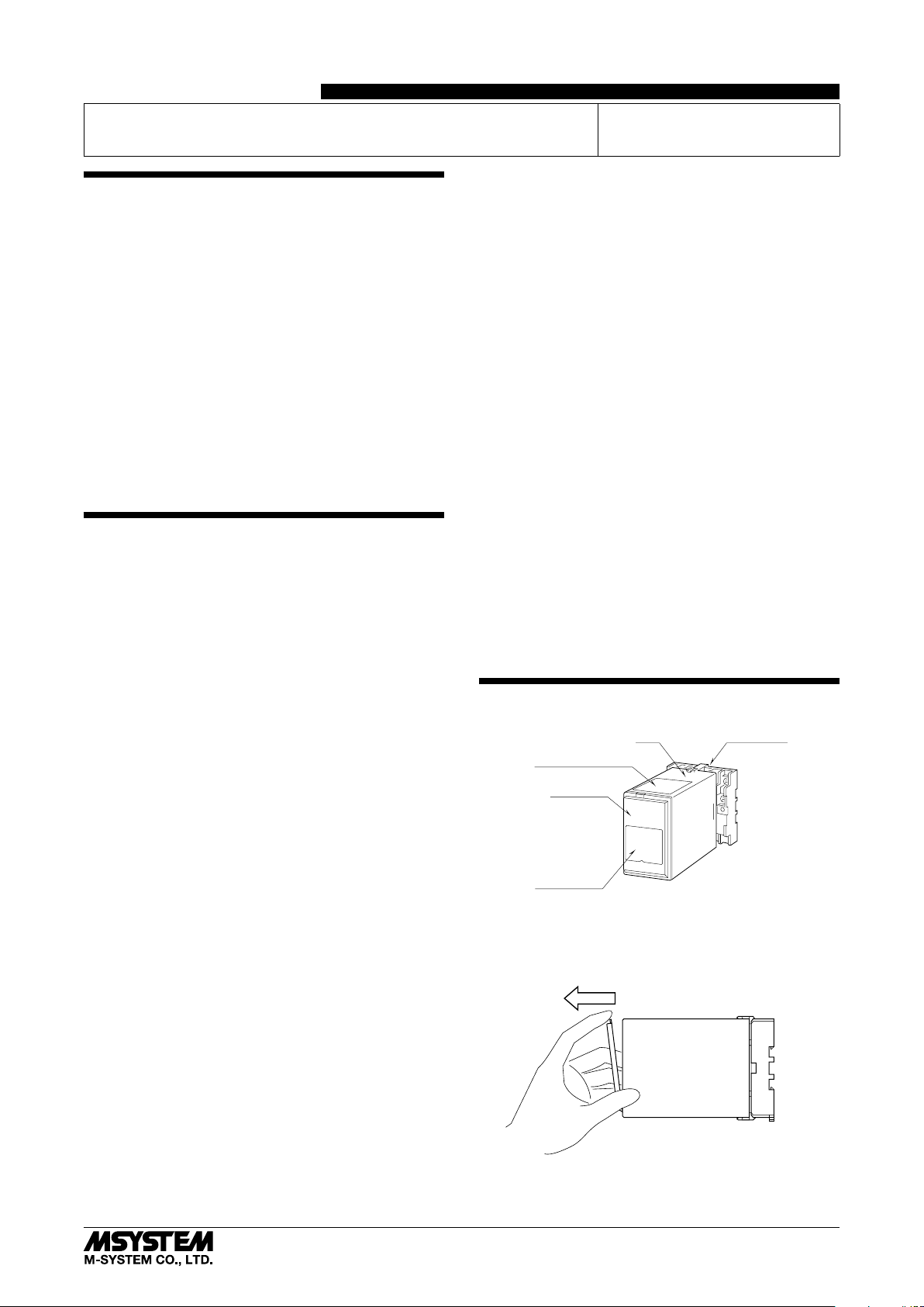
COMPONENT IDENTIFICATION
Body Base Socket
Connection Diagram
Front Cover
Specifications
■ HOW TO OPEN THE FRONT COVER:
Position your finger on the hook at the top of the front cover
and pull.
The shape of base socket may be different
for some models.
EM-2222 Rev.1 P. 1 / 4
Page 2
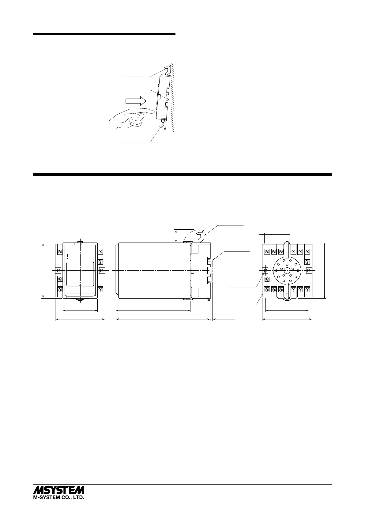
INSTALLATION
Shape and size of the base socket
are slightly different with various
socket types.
Detach the yellow clamps located at the top and bottom of
the unit for separate the body from the base socket.
WRPP
■ DIN RAIL MOUNTING
Set the base socket so that its
DIN rail adaptor is at the bot-
Clamp
(top & bottom)
DIN Rail
35mm wide
tom. Position the upper hook
at the rear side of base socket
on the DIN rail and push in
the lower. When removing the
socket, push down the DIN
rail adaptor utilizing a minus
screwdriver and pull.
Spring Loaded
DIN Rail Adaptor
■ WALL MOUNTING
Refer to “EXTERNAL DIMENSIONS.”
TERMINAL CONNECTIONS
Connect the unit as in the diagram below or refer to the connection diagram on the top of the unit.
■ EXTERNAL DIMENSIONS unit: mm (inch)
CLAMP
(top & bottom)
20
(.79)
DIN RAIL
35mm wide
7
7.8 (.31)
14
12
56
4
3
80 (3.15)
50 (1.97)
72 (2.83)
107 (4.21)
136 (5.35) [3.3 (.13)]
• When mounting, no extra space is needed between units.
2–4.5 (.18) dia.
MTG HOLE
25 (.98) deep
14–M3.5
SCREW
8
9
1
1015
60 (2.36)
72 (2.83)
11
80 (3.15)
2
5-2-55, Minamitsumori, Nishinari-ku, Osaka 557-0063 JAPAN
Phone: +81(6)6659-8201 Fax: +81(6)6659-8510 E-mail: info@m-system.co.jp
EM-2222 Rev.1 P. 2 / 4
Page 3

■ CONNECTION DIAGRAM
■
8
+
PHASE A
INPUT
PHASE B
9
−
10
+
15
−
12
11
14
WRPP
+
4
PHASE A
−
+
5
−
6
+
1
−
+
2
−
3
U (+)
7
V (−)
OUTPUT 1
PHASE B
PHASE A
OUTPUT 2
PHASE B
POWER
Input Connection Examples
■ Dry Contact Input ■ Open Collector Output ■ Voltage Pulse Output■ Open Collector Output ■ RS-422 Line Driver Pulse Output
+
8
–
9
+
10
–
15
500Ω
■ Voltage Pulse Input
8
+
–
9
10
+
–
15
RS-422 Line Driver Pulse Input
Phase A
Phase A
Phase B
Rotary Encoder
Phase B
Output Connection Examples
5V
8
+
9
−
10
+
15
−
RS-422
Receiver
RS-422
Receiver
12
11
4
5
6
1
2
3
+
+
–
−
+
+
–
−
+
+
–
−
+
+
–
−
12
11
4
+
+
–
−
5
+
+
6
1
2
3
–
−
+
+
–
−
+
+
–
−
12
11
+
4
+
−
5
+
6
−
1
+
−
2
+
3
−
+
–
–
+
+
–
–
+
+
–
–
+
+
–
–
FUNCTIONS & OPERATIONS
The unit is designed to isolate two phase pulse from a rotary encoder and distribute it into two outputs.
• Capable of handling voltage pulse, dry contact and RS-422 line driver pulse input signals.
• Capable of handling voltage pulse, open collector and RS-422 line driver pulse output signals.
• Kinds of signals (input, output 1 and output 2) are selectable.
• Maximum available frequency is 1 MHz. (It varies depending on kinds of signals.)
5-2-55, Minamitsumori, Nishinari-ku, Osaka 557-0063 JAPAN
Phone: +81(6)6659-8201 Fax: +81(6)6659-8510 E-mail: info@m-system.co.jp
EM-2222 Rev.1 P. 3 / 4
Page 4

OUTPUT LOGIC
WRPP
Voltage pulse
RS-422 line driver pulse
H
L
H
L
H
L
OFF
ON
OFF
ON
Output
Voltage pulse
or
RS-422 line
driver pulse
Open collector
Input
Non-inverted
Inverted
Non-inverted
Inverted
CHECKING
1) Terminal wiring: Check that all cables are correctly connected according to the connection diagram.
2) Power input voltage: Check voltage across the terminal
7 – 14 with a multimeter.
3) Input:
• Check that the frequency is within the range described
below.
Dry contact, 12 V / 24 V pulse: ≤ 100 kHz
5 V pulse: ≤ 500 kHz
3.3 V pulse, RS-422 line driver pulse: ≤ 1 MHz
And also, check that it doesn’t exceed the maximum fre-
quency of output signal.
• When operating at frequencies close to the maximum frequency, use pulse duty at approx. 50%.
4) Output: Check that the load voltage meets the specifications described in the table below.
OUTPUT SIGNAL LOAD VOLTAGE
Open Collector 50 V DC ≤ 100 mA
3.3 V ≥ 660 Ω
Voltage Pulse
5) Open the front cover to check the input pulse status with
monitor LEDs.
Phase A: Green, Phase B: Red, Input low: LED on
(LED on/off is not defined at input opened.)
5 V ≥ 1 kΩ
12 V ≥ 2.4 kΩ
Dry contact
OFF
ON
H
L
H
L
OFF
ON
OFF
ON
LIGHTNING SURGE PROTECTION
M-System offers a series of lightning surge protector for
protection against induced lightning surges. Please contact
M-System to choose appropriate models.
■ FRONT VIEW
InputMonitorLEDPhaseB(Red)
InputMonitorLEDPhaseA(Green)
5-2-55, Minamitsumori, Nishinari-ku, Osaka 557-0063 JAPAN
Phone: +81(6)6659-8201 Fax: +81(6)6659-8510 E-mail: info@m-system.co.jp
EM-2222 Rev.1 P. 4 / 4
 Loading...