

Page 1
5-2-55, Minamitsumori, Nishinari-ku, Osaka 557-0063 JAPAN
Phone: +81(6)6659-8201 Fax: +81(6)6659-8510 E-mail: info@m-system.co.jp
EM-9080-A P. 1 / 8
INSTRUCTION MANUAL
WIRELESS GATEWAY
(Modbus/TCP (Ethernet), Modbus-RTU Transparent
900 MHz Band Wireless Device (Child device))
MODEL
WL40EW2F
BEFORE USE ....
Thank you for choosing M-System. Before use, please check
contents of the package you received as outlined below.
If you have any problems or questions with the product,
please contact M-System’s Sales Office or representatives.
■ PACKAGE INCLUDES:
Wireless gateway.................................................................(1)
Antenna ...............................................................................(1)
■ MODEL NO.
Confirm Model No. marking on the product to be exactly
what you ordered.
■ INSTRUCTION MANUAL
This manual describes necessary points of caution when
you use this product, including installation, connection and
basic maintenance procedures.
For information on the introduction of wireless device, refer
to the 900 MHz band wireless device users manual (EM-
9085).
For information on the detailed setting, refer to the operating manual (NM-9080-B).
For information on Modbus specification, refer to the Modbus Protocol Reference Guide (EM-5650).
These manuals are downloadable at M-System’s web site
(http://www.m-system.co.jp).
POINTS OF CAUTION
■ POWER INPUT RATING & OPERATIONAL RANGE
•Locate the power input rating marked on the product and
confirm its operational range as indicated below:
24V DC rating: 24V ±10%, ≤ 90mA
12V DC rating: 12V ±10%, ≤ 170mA
■ GENERAL PRECAUTIONS
•Before you remove the unit or mount it, turn off the power
supply for safety.
■ ENVIRONMENT
•Indoor use.
•When heavy dust or metal particles are present in the
air, install the unit inside proper housing with sufficient
ventilation.
•Do not install the unit where it is subjected to continuous
vibration. Do not subject the unit to physical impact.
•Environmental temperature must be within -20 to +60°C
(-4 to 140°F) with relative humidity within 10 to 90% RH
in order to ensure adequate life span and operation.
•Attach the antenna to the unit.
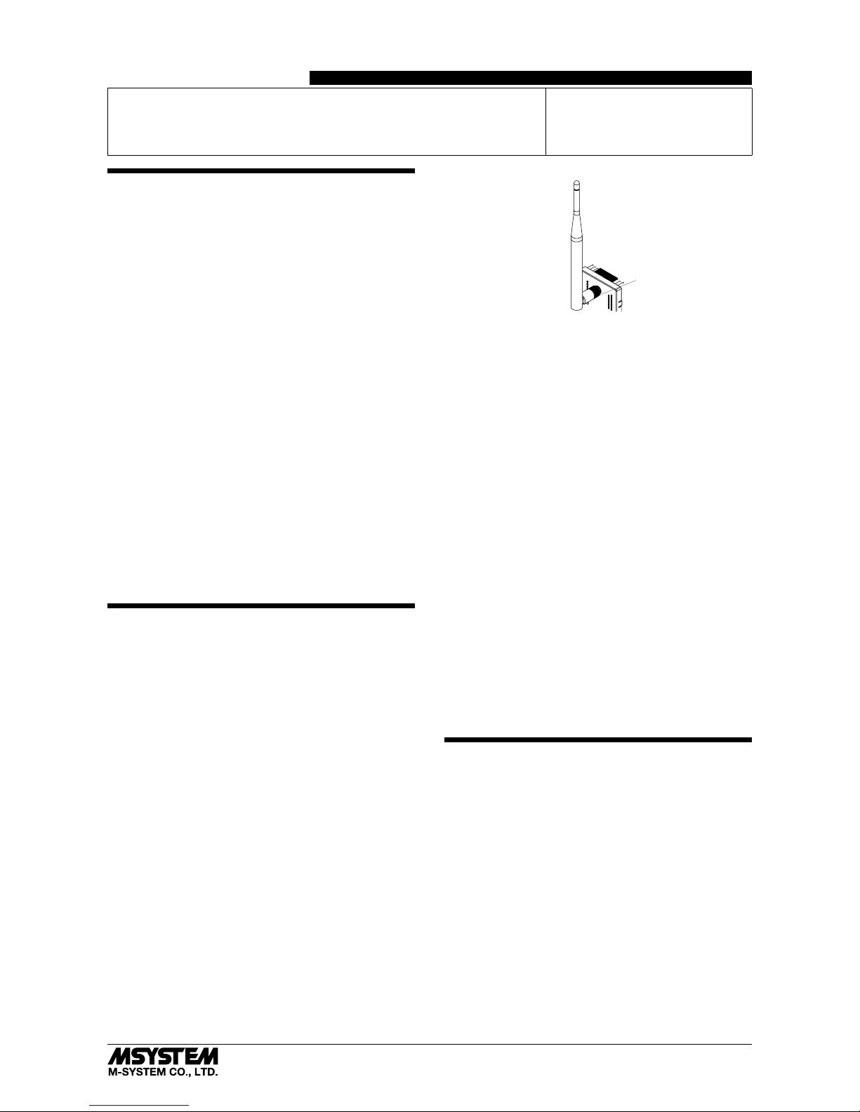
•Attachment and adjustment of sleeve antenna; Loosen
the connector (See the top-right figure.), and rotate the
antenna. Holding the antenna vertical, tighten the connector by hand. Make sure to fix the antenna firmly.
Connector
•Attachment of rooftop antenna; There is a magnet on the
bottom face which allows you to attach the antenna on
a metal box and such. To obtain optimum performance
from the antenna, attach on a metal plate (recommended
dimension: 500 mm × 500 mm or more). However, in the
case of connecting FE1 to a metal plate, the isolation between FE1 and antenna connector will be lost. Tighten
the connector with a specified torque (0.9 N∙m). As a
guide, finger-tighten it until the connector stops, and then
rotate it 10 to 15 degrees with a wrench. Do not force the
cable to bend less than acceptable radius of 3 cm.
•Using 7.5 m coaxial cable (model: CX-SAC0SAD0Q0750)
(OKI) for extension decreases transmission distance.
■ WIRING
•Do not install cables close to noise sources (relay drive
cable, high frequency line, etc.).
•Do not bind these cables together with those in which
noises are present. Do not install them in the same duct.
•Use a shielded twisted pair (STP) cable as a LAN cable.
■ AND ....
•The unit is designed to function as soon as power is supplied, however, a warm up for 10 minutes is required for
satisfying complete performance described in the data
sheet.
CAUTION REGARDING RADIO FREQUENCY
■ FCC NOTICE
•This device complies with part 15 of the FCC Rules.
Operation is subject to the following two conditions:
(1) This device may not cause harmful interference, and
(2) this device must accept any interference received, in-
cluding interference that may cause undesired operation.
■ FCC CAUTION
•Changes or modifications not expressly approved by the
party responsible for compliance could void the user’s authority to operate the equipment.
Page 2
WL40EW2F
5-2-55, Minamitsumori, Nishinari-ku, Osaka 557-0063 JAPAN
Phone: +81(6)6659-8201 Fax: +81(6)6659-8510 E-mail: info@m-system.co.jp
EM-9080-A P. 2 / 8
■ NOTE
•This equipment has been tested and found to comply with
the limits for a Class A digital device, pursuant to part 15
of the FCC Rules. These limits are designed to provide
reasonable protection against harmful interference when
the equipment is operated in a commercial environment.
This equipment generates, uses, and can radiate radio
frequency energy and, if not installed and used in accordance with the instruction manual, may cause harmful
interference to radio communications. Operation of this
equipment in a residential area is likely to cause harmful
interference in which case the user will be required to correct the interference at his own expense.
•This transmitter must not be co-located or operated in
conjunction with any other antenna or transmitter.
■ FCC RF EXPOSURE INFORMATION
•This equipment complies with FCC radiation exposure
limits set forth for an uncontrolled environment and
meets the FCC radio frequency (RF) Exposure Guidelines. This equipment should be installed and operated
keeping the radiator at least 20 cm or more away from
person’s body.
FCC ID : 2AOTF-0000001
Contains FCC ID: 2AKGW-1TD3016A1
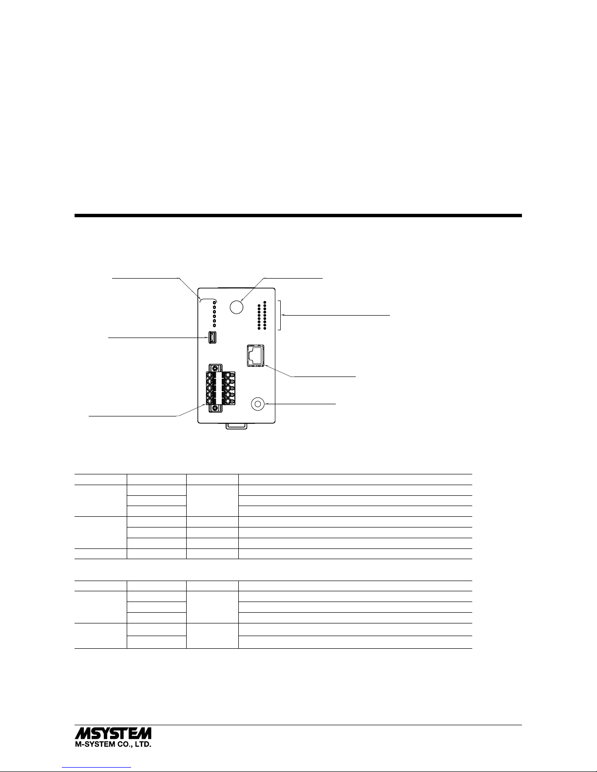
COMPONENT IDENTIFICATION
Network Status Indicator LED
*Power input defers depending on the power input code you select.
Status Indicator LED
Antenna Connector
Maintenance Connector
Connector for Power Input *
Power
920Link
920Run
CFG
24V
0V
NC
NC
FE1
RJ-45 Modular jack
Link
Link100
Ethernet
IP Reset
Reset Switch
■ FRONT VIEW
■ STATUS INDICATOR LED
ID STATU S COLOR FUNCTION
Power ON Green Power is on.
Blinking Reset switch is on.
OFF Power is off, or device error occurring.
920Link ON Green 900 MHz band wireless: operating
0.5 Hz blinking Green 900 MHz band wireless: starting up
OFF Green 900 MHz band wireless: stopping
920Run ON Green 900 MHz band wireless: normal communication with child device
■ NETWORK STATUS INDICATOR LED
ID STATU S COLOR FUNCTION
Link ON Green Linking via 10BASE or 100BASE
Blinking Sending / Receiving data
OFF No link
Link100
ON
Green
Linking via 100BASE
OFF Linking via 10BASE or no link
■ RESET SW
Press and hold the SW for two seconds or more, so that Power LED blinks and the existing settings are initialized to the factory settings. Release the SW after confirming the power LED is blinking, so that the initialization starts and the unit reboots.
Use this procedure if you are not sure of IP address or other settings.
Page 3

WL40EW2F
5-2-55, Minamitsumori, Nishinari-ku, Osaka 557-0063 JAPAN
Phone: +81(6)6659-8201 Fax: +81(6)6659-8510 E-mail: info@m-system.co.jp
EM-9080-A P. 3 / 8
■ TERMINAL ASSIGNMENTS
• Connectors for power input
Unit side connector: MSTBV2,5/5-GF-5,08AU (Phoenix Contact)
Cable side connector: TFKC2,5/5-STF-5,08AU (Phoenix Contact)
Power input code: R (24 V DC) Power input code: S (12 V DC)
24V
0V
NC
NC
FE1
ID FUNCTION
12V
0V
NC
NC
FE1
ID FUNCTION
24V Power input 24 V 12V Power input 12 V
0V Power input 0 V 0V Power input 0 V
NC Not used NC Not used
NC Not used NC Not used
FE1 Power input earth FE1 Power input earth
Page 4

WL40EW2F
5-2-55, Minamitsumori, Nishinari-ku, Osaka 557-0063 JAPAN
Phone: +81(6)6659-8201 Fax: +81(6)6659-8510 E-mail: info@m-system.co.jp
EM-9080-A P. 4 / 8
WEB BROWSER SETTING
With web browser, settings shown below are available.
Refer to the operating manual of EM-9080-B for detailed operation.
■ TCP / IP SETTING
ITEM SETTING RANGE DEFAULT
IP address 1.0.0.0 – 223.255.255.255 192.168.0.1
Subnet mask 224.0.0.0 – 255.255.255.255 255.255.255.0
Default gateway 0.0.0.0 – 255.255.255.255 0.0.0.0
■ MODBUS / TCP SETTING
ITEM SETTING RANGE DEFAULT
Port 1 – 65535 502
Modbus exception response Not return 06 (BUSY), 0B (ERROR) /
Return 06 (BUSY), 0B (ERROR)
Return 06 (BUSY), 0B (ERROR)
Communication timeout 1 – 60 (min.) 1 (min.)
■ WIRELESS SETTING
ITEM SETTING RANGE DEFAULT
PAN ID (group number) 0000 – FFFE (hexadecimal, 4 digits) 0000
Radio channel number 1 – 43ch 1ch
Network name English one-byte characters within 16 characters
(one-byte space, “-”, “_”, “.”, “@” are usable.)
MH920
Encryption key 0000...0 – FFFF...F
(hexadecimal, 32 digits)
0000...0
Prefix 2000:0000:0000:0000 – 3FFF:FFFF:FFFF:FFFF 2000:0000:0000:0000
Transmitter power output 0.16mW / 1mW / 20mW 20mW
Device type in a network,
Number of devices in a network
Child (fixed), 1 to 30 devices /
Child (fixed), 31 to 60 devices /
Child (fixed), 61 to 100 devices /
Child (fixed) + child (moving)
Child (fixed), 1 to 30 devices
Set network quality Standard (recommended) /
Frequency of route switching and delay (higher) /
Frequency of route switching and delay (highest)
Standard (recommended)
Network join mode V3-compatible mode / Fast join mode V3-compatible mode
Packet filtering None / Yes (polling type) Yes (polling type)
Filter timeout on polling 1.0 – 60.0 (sec.) 4.0 (sec.)
Setting mode of short address Range mode: 1 device (max. multi drop number)
Range mode: 1 to 4 devices (max. multi drop number)
Range mode: 1 to 8 devices (max. multi drop number)
Range mode: 1 to 16 devices (max. multi drop number)
Range mode: 1 to 31 devices (max. multi drop number)
List mode
List mode
920Run timeout 0.0 – 3200.0 (sec.) 5.0 (sec.)
Retry times before route switching Once / Twice / Three times Three times
Short address list setting Short address
—
MAC address list setting MAC address
—
Connection refusal list setting MAC address
—
Note: For version confirmation of communication module, refer to the operating manual of EM-9080-B for detailed operation.
Page 5

WL40EW2F
5-2-55, Minamitsumori, Nishinari-ku, Osaka 557-0063 JAPAN
Phone: +81(6)6659-8201 Fax: +81(6)6659-8510 E-mail: info@m-system.co.jp
EM-9080-A P. 5 / 8
INSTALLATION
■ DIN RAIL MOUNTING
A) Hang the upper hook at the back of the unit on the DIN
rail.
B) Push the lower part of the unit to fit in the DIN rail.
A
B
■ DEMOUNTING
A) Pull down the DIN rail adaptor using a minus screw-
driver.
B) Pull out the lower part of the unit.
C) Remove the upper part from the DIN rail.
A
B
C
Page 6
WL40EW2F
5-2-55, Minamitsumori, Nishinari-ku, Osaka 557-0063 JAPAN
Phone: +81(6)6659-8201 Fax: +81(6)6659-8510 E-mail: info@m-system.co.jp
EM-9080-A P. 6 / 8
TERMINAL CONNECTIONS
Connect the unit as in the diagram below.
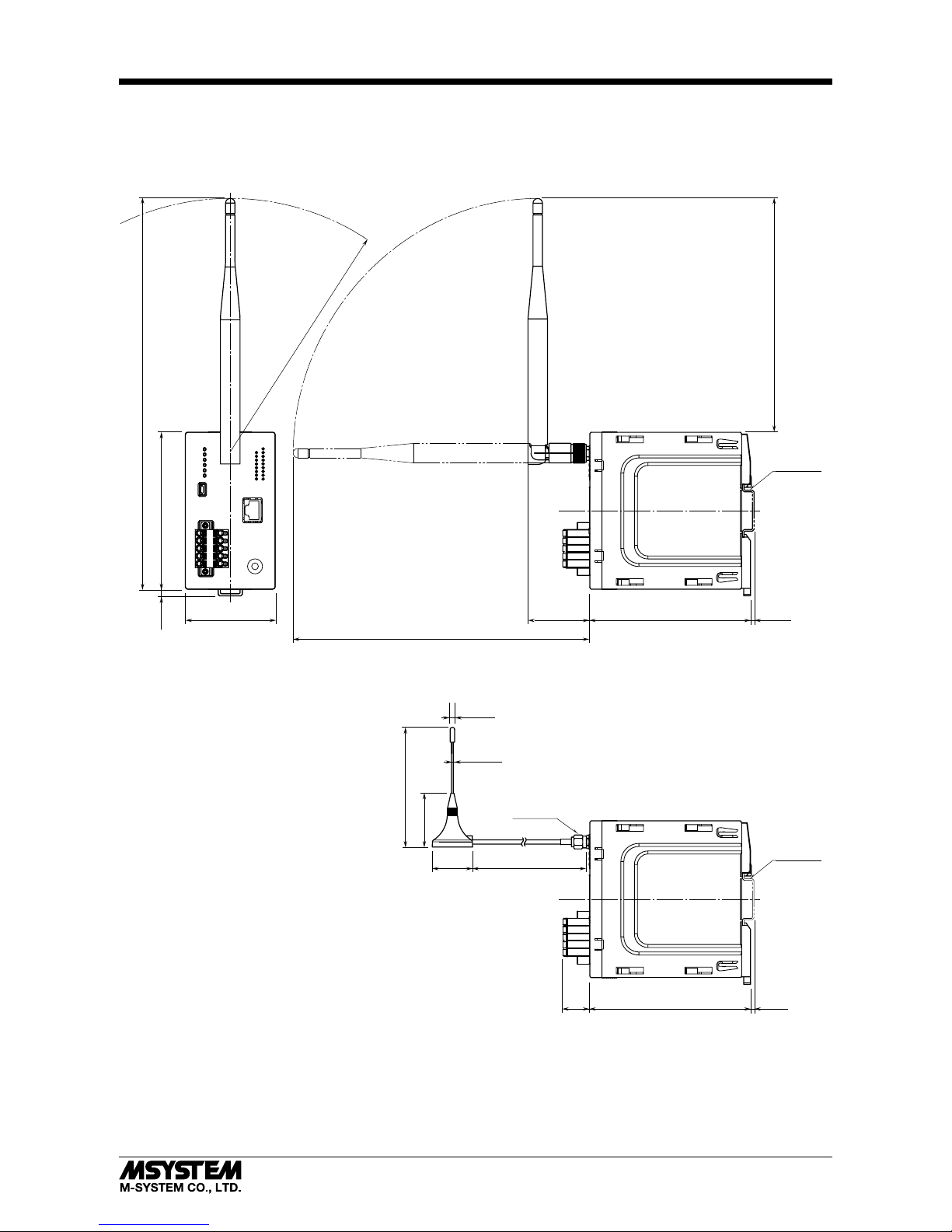
■ EXTERNAL DIMENSIONS unit: mm (inch)
105 (4.13)
[260 (10.24)]
60 (2.36)
107 (4.21)
107 (4.21)
3 (.12)
3 (.12)
45 (1.77)
[200 (7.87)]
20
(.79)
approx. 2500 (98.4)ø27
(1.06)
ø3 (.12)
ø1.2 (.05)
36 (1.42)
80 (3.15)
5 (.20)
[155 (6.10)]
[R165 (6.50)]
• With sleeve antenna
• With rooftop antenna
DIN RAIL
35mm wide
DIN RAIL
35mm wide
8 (.31) Hex.
Page 7
WL40EW2F
5-2-55, Minamitsumori, Nishinari-ku, Osaka 557-0063 JAPAN
Phone: +81(6)6659-8201 Fax: +81(6)6659-8510 E-mail: info@m-system.co.jp
EM-9080-A P. 7 / 8
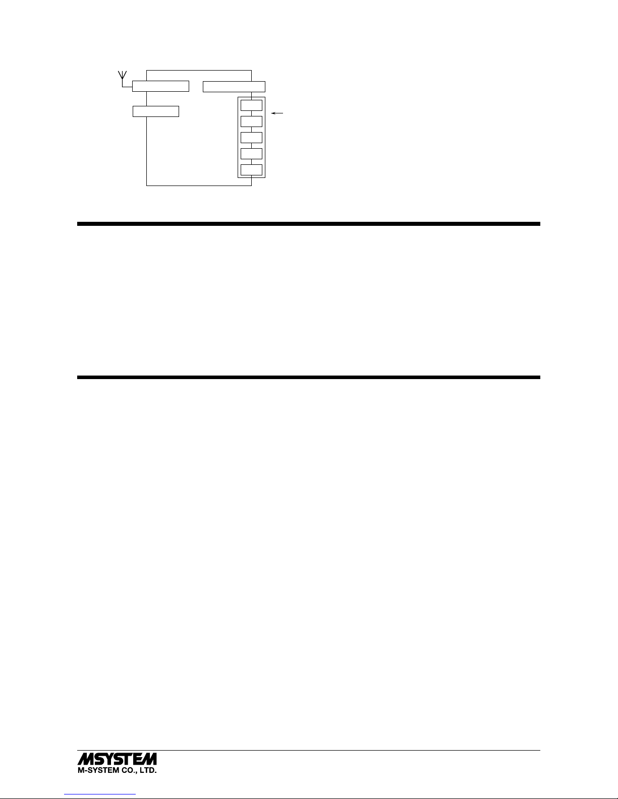
■ CONNECTION DIAGRAM
Power Input
Maintenance
Connector
To Other
Ethernet Devices
* Power input defers depending on the power input code you select.
RJ-45 Modular Jack
USB Connector
Antenna Connector
NC
NC
FE1
0V
24V
*
WIRING INSTRUCTIONS
■ TENSION CLAMP (FRONT TWIN CONNECTION) FOR POWER INPUT
Applicable wire size: 0.2 to 2.5 mm
2
Stripped length: 10 mm
Recommended terminals:
AI0,25-10YE 0.25 mm
2
(Phoenix Contact)
AI0,34-10TQ 0.34 mm
2
(Phoenix Contact)
AI0,5-10WH 0.5 mm
2
(Phoenix Contact)
AI0,75-10GY 0.75 mm
2
(Phoenix Contact)
AI1-10RD 1.0 mm
2
(Phoenix Contact)
AI1,5-10BK 1.5 mm
2
(Phoenix Contact)
AI2,5-10BU 2.5 mm
2
(Phoenix Contact)
CONFIRMING ETHERNET CONNECTION
■ PREPARATION FOR NETWORK CONNECTION
To configure the settings for the device WL40EW2F via a network, a Windows PC, which can be connected to the network, is
required. Confirm the settings of destinations such as the PC.
1) Connect the device and the PC with a LAN cable (STP cable).
2) Set PC’s IP address “192.168.0.xxx” which is not the same as the device. (example: 192.168.0.10)
Set subnet mask “255.255.255.0”. (Factory default IP address of the device is “192.168.0.1”.)
■ SETTING FOR THE DEVICE
1) Activate web browser, and enter the IP address of the device following “http://” in the address bar.
If this is the first-time connection, enter the factory default IP address as below.
http://192.168.0.1./
Web browser (recommended): Microsoft Internet Explorer 11 or more
2) Enter user name and password.
“admin” as user name and “admin” as password are designated for the first time connection.
3) For various settings, refer to the users manual (EM-9080-B) for detailed operation.
■ CONNECTION TO NETWORK
When wiring is correct, LED of LINK or LINK100 is ON or blinks.
Page 8

WL40EW2F
5-2-55, Minamitsumori, Nishinari-ku, Osaka 557-0063 JAPAN
Phone: +81(6)6659-8201 Fax: +81(6)6659-8510 E-mail: info@m-system.co.jp
EM-9080-A P. 8 / 8
■ CHECK FOR WL40EW2F CONNECTION
Open Command Prompt in Windows, and enter “ping command” as follows:
C: ¥WINDOWS > ping ***.***.***.***
(***.***.***.***: Enter IP address in decimal.)
ping ***.***.***.*** with 32 bytes of data:
Reply from ***.***.***.*** : bytes=32 time < 10ms TTL = 64
Reply from ***.***.***.*** : bytes=32 time < 10ms TTL = 64
Reply from ***.***.***.*** : bytes=32 time < 10ms TTL = 64
Reply from ***.***.***.*** : bytes=32 time < 10ms TTL = 64
Ping statistics for ***.***.***.***
Packets : Sent = 4, Received = 4, Lost = 0 (0% loss)
Replies in case of normal connection are as shown above. If the connection cannot be established normally due to e.g. wrong
IP address, other replies such as ‘timeout’ will be received.
MODBUS FUNCTION CODE
Modbus function codes are shown below.
■ DATA AND CONTROL FUNCTIONS
CODE NAME
01 Read Coil Status Digital output from the slave (read/write)
02 Read Input Status Status of digital inputs to the slave (read only)
03 Read Holding Registers General purpose register within the slave (read/write)
04 Read Input Registers Collected data from the field by the slave (read only)
05 Force Single Coil Digital output from the slave (read/write)
06 Preset Single Registers General purpose register within the slave (read/write)
15 Force Multiple Coils Digital output from the slave (read/write)
16 Preset Multiple Registers General purpose register within the slave (read/write)
■ EXCEPTION CODES
CODE NAME
06 Slave Device Busy Device’s Modbus/TCP request queue is full.
11 Gateway Target Device Failed To Respond Response from 900 MHz band wireless device (child) is error, or response
timeout occurred.
Note: When 900 MHz band wireless device (child) returns an exception code other than the above, the exception code is directly
transmitted to upper devices.
LIGHTNING SURGE PROTECTION
M-System offers a series of lightning surge protector for
protection against induced lightning surges. Please contact
M-System to choose appropriate models.
 Loading...