

Page 1

5-2-55, Minamitsumori, Nishinari-ku, Osaka 557-0063 JAPAN
Phone: +81(6)6659-8201 Fax: +81(6)6659-8510 E-mail: info@m-system.co.jp
EM-5512 Rev.8 P. 1 / 3
INSTRUCTION MANUAL
THERMOCOUPLE TRANSMITTER
MODEL
W2TS
BEFORE USE ....
Thank you for choosing M-System. Before use, please check
contents of the package you received as outlined below.
If you have any problems or questions with the product,
please contact M-System’s Sales Office or representatives.
■ PACKAGE INCLUDES:
Signal conditioner (body + base socket + CJC sensor) ......(1)
■ MODEL NO.
Confirm Model No. marking on the product to be exactly
what you ordered.
■ INSTRUCTION MANUAL
This manual describes necessary points of caution when
you use this product, including installation, connection and
basic maintenance procedures.
POINTS OF CAUTION
■ WARNING
•If equipment is not used in a manner not specified by MSystem, the protection provided by the equipment may
be impaired.
■ NONINCENDIVE APPROVAL OPTION
•This equipment is suitable for use in Class I, Div. 2,
Groups A, B, C and D or Non-Hazardous Locations only.
•WARNING! Before You Remove the Unit from Its Base
Socket or Mount It, Turn Off the Power Supply and Input
Signal for Safety.
•WARNING! – Explosion Hazard –
Substitution of any Components May Impair Suitability
for Class I, Div. 2.
•WARNING! – Explosion Hazard –
Do Not Disconnect Equipment Unless Power Has Been
Switched Off or The Area is Known To Be Non-Hazardous.
•The equipment was evaluated for use in the ambient temperature and relative humidity as mentioned in ‘ENVIRONMENT’ section.
•The input and output wiring must be in accordance with
Class I, Div. 2 wiring methods and in accordance with the
authority having jurisdiction for use in these hazardous
locations.
■ CONFORMITY WITH EU DIRECTIVES OR UL
•This equipment is suitable for Pollution Degree 2 and
Installation Category II (transient voltage 2500 V). Reinforced insulation (signal input or output 1 or output 2
to power input: 300V) and basic insulation (signal input
to output 1 or output 2: 300V) are maintained. Prior to
installation, check that the insulation class of this unit
satisfies the system requirements.
•Altitude up to 2000 meters.
•The equipment must be mounted inside a panel.
•Insert noise filters for the power source, input and output
connected to the unit. COSEL Model NAC-04-472, TDK
Model ZCAT 3035-1330 or equivalent is recommended.
•The equipment must be installed such that appropriate
clearance and creepage distances are maintained to conform to CE/UL requirements. Failure to observe these
requirements may invalidate the CE/UL conformance.
•The actual installation environments such as panel configurations, connected devices, connected wires, may affect the protection level of this unit when it is integrated
in a panel system. The user may have to review the CE
requirements in regard to the whole system and employ
additional protective measures to ensure the CE conformity.
•Install lightning surge protectors for those wires connected to remote locations.
■ POWER INPUT RATING & OPERATIONAL RANGE
•Locate the power input rating marked on the product and
confirm its operational range as indicated below:
100 – 240V AC rating: 85 – 264V (90 – 264V for UL),
47 – 66 Hz, approx. 4 – 6VA
24V DC rating: 24V ±10%, approx. 3W
11 – 27V DC rating: 11 – 27V, approx. 3W
110V DC rating: 85 – 150V (110V ±10% for UL), approx. 3W
■ GENERAL PRECAUTIONS
•Before you remove the unit from its base socket or mount
it, turn off the power supply and input signal for safety.
■ ENVIRONMENT
•Indoor use.
•When heavy dust or metal particles are present in the
air, install the unit inside proper housing with sufficient
ventilation.
•Do not install the unit where it is subjected to continuous
vibration. Do not subject the unit to physical impact.
•Environmental temperature must be within -5 to +55°C
(23 to 131°F) with relative humidity within 30 to 90% RH
in order to ensure adequate life span and operation.
•Be sure that the ventilation slits are not covered with cables, etc.
■ WIRING
•Do not install cables close to noise sources (relay drive
cable, high frequency line, etc.).
•Do not bind these cables together with those in which
noises are present. Do not install them in the same duct.
■ AND ....
•The unit is designed to function as soon as power is supplied, however, a warm up for 10 minutes is required for
satisfying complete performance described in the data
sheet.
•With voltage output, do not leave the output terminals
shortcircuited for a long time. The unit is designed to
endure it without breakdown, however, it may shorten appropriate life duration.
Page 2
W2TS
5-2-55, Minamitsumori, Nishinari-ku, Osaka 557-0063 JAPAN
Phone: +81(6)6659-8201 Fax: +81(6)6659-8510 E-mail: info@m-system.co.jp
EM-5512 Rev.8 P. 2 / 3
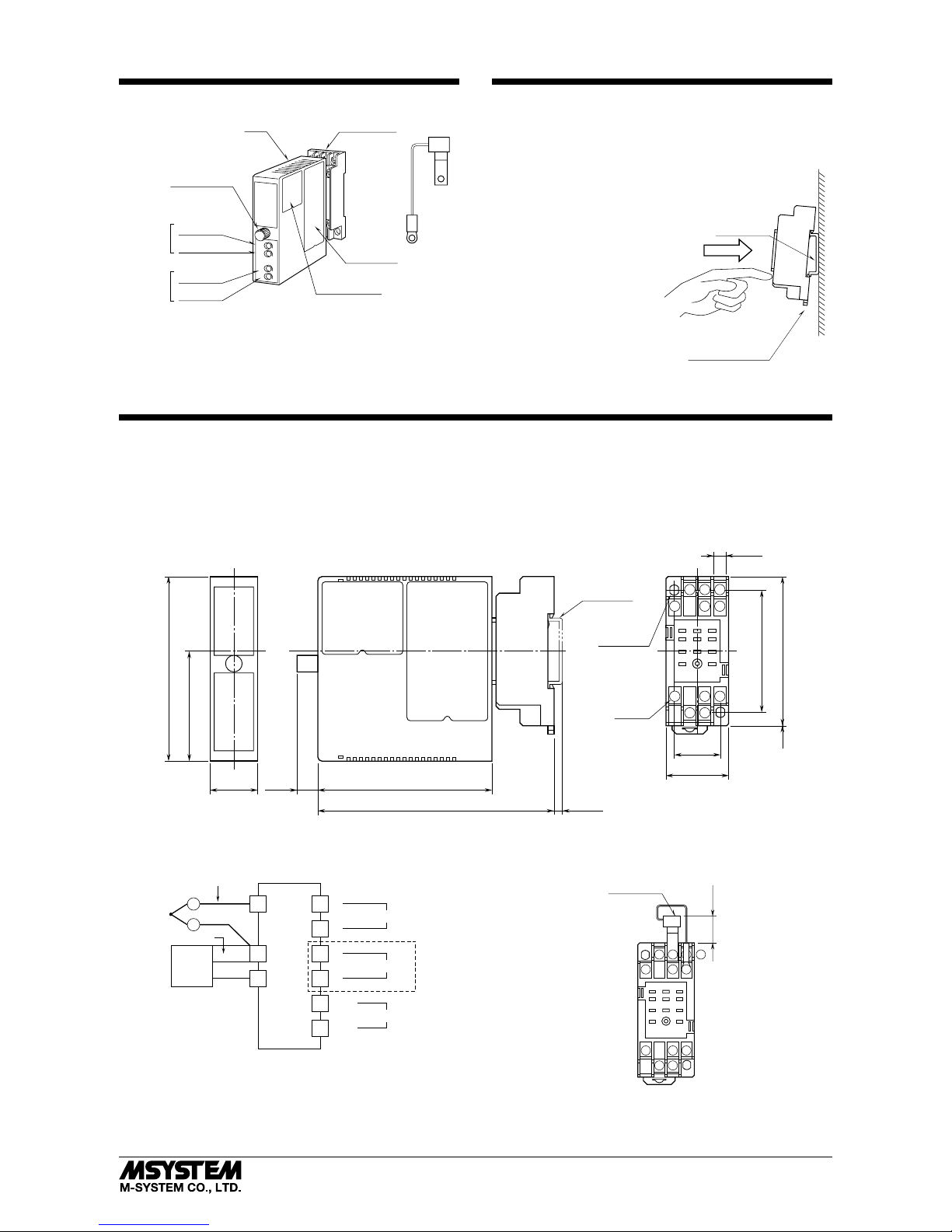
COMPONENT IDENTIFICATION
CJC
Sensor
Model
SPAN
ZERO
SPAN
ZERO
Fixing Screw
Zero Adj.
Span Adj.
Zero Adj.
Span Adj.
Connection
Diagram
Specifications
Output 1
Output 2*
*Provided only for dual output.
Body
Base Socket
INSTALLATION
Loosen the fixing screw at the front of the unit in order to
separate the body from the base socket.
■ DIN RAIL MOUNTING
Set the base socket so that
its DIN rail adaptor is at
the bottom. Position the
upper hook at the rear side
of base socket on the DIN
rail and push in the lower.
When removing the socket,
push down the DIN rail
adaptor utilizing a minus
screwdriver and pull.
■ WALL MOUNTING
Refer to “EXTERNAL DIMENSIONS.”
DIN Rail
35mm wide
Spring Loaded
DIN Rail Adaptor
TERMINAL CONNECTIONS
Connect the unit as in the diagram below or refer to the connection diagram on the side of the unit.
Attach the CJC sensor together with input wiring to the input terminals. The CJC sensor is not interchangeable. Check that
its serial number is identical to that of the unit.
■ EXTERNAL DIMENSIONS unit: mm (inch)
4
8 7
10
21.5 (.87)
88.5 (3.48)
84 (3.31)10 (.39)
22 (.87)
59 (2.32)
DIN RAIL
35mm wide
[4 (.16)]
11
–
M3
SCREW
72 (2.83)
29.5 (1.16)
53 (2.09)
2–4.2x5
(.17x.20)
MTG HOLE
6 (.24) deep
114 (4.49)
11
56
123
9
6 (.23)
• When mounting, no extra space is needed between units.
4
(.16)
■ CONNECTION DIAGRAM
U(+)
V(–)
POWER
10
11
+
–
OUTPUT 1
7
8
+
–
3
6
OUTPUT 2
1
+
–
T / C
CJC
SENSOR
metal leg
model: CJM
comp. leadwire
4
2
+
–
The section enclosed by broken line is only with 2nd output option.
■ TERMINAL ASSIGNMENTS unit: mm (inch)
8 7
1011
56
391
CJC SENSOR
(model: CJM)
14 (.55)
12
4
Page 3

W2TS
5-2-55, Minamitsumori, Nishinari-ku, Osaka 557-0063 JAPAN
Phone: +81(6)6659-8201 Fax: +81(6)6659-8510 E-mail: info@m-system.co.jp
EM-5512 Rev.8 P. 3 / 3
CHECKING
1) Terminal wiring: Check that all cables are correctly connected according to the connection diagram.
2) Power input voltage: Check voltage across the terminal
10 – 11 with a multimeter.
3) Input: Check that the input voltage is within 0 – 100% of
full-scale.
If the thermocouple or its extension wires are broken, the
output goes over 100% (below 0% with downscale) due
to the burnout function. Check leadwires in such a case.
4) Output: Check that the load resistance meets the described specifications.
ADJUSTMENT PROCEDURE
This unit is calibrated at the factory to meet the ordered
specifications, therefore you usually do not need any calibration.
For matching the signal to a receiving instrument or in case
of regular calibration, adjust the output as explained in the
following.
■ HOW TO CALIBRATE THE OUTPUT SIGNAL
Use a signal source and measuring instruments of sufficient
accuracy level. Turn the power supply on and warm up for
more than 10 minutes.
1) ZERO: Apply 0% input and adjust output to 0%.
2) SPAN: Apply 100% input and adjust output to 100%.
3) Check ZERO adjustment again with 0% input.
4) When ZERO value is changed, repeat the above procedure 1) – 3).
5) Go through the same procedure for the Output 2.
MAINTENANCE
Regular calibration procedure is explained below:
■ CALIBRATION
Warm up the unit for at least 10 minutes. Apply 0%, 25%,
50%, 75% and 100% input signal. Check that the output
signal for the respective input signal remains within accuracy described in the data sheet. When the output is out of
tolerance, recalibrate the unit according to the “ADJUSTMENT PROCEDURE” explained earlier.
LIGHTNING SURGE PROTECTION
M-System offers a series of lightning surge protector for
protection against induced lightning surges. Please contact
M-System to choose appropriate models.
 Loading...