

Page 1

TM
P. 1 / 2 EM-3315 Rev.5
INSTRUCTION MANUAL
MODEL
TM
POTENTIOMETER TRANSMITTER
INSTALLATION
■ DIN RAIL MOUNTING
Set the unit so that its DIN rail adaptor is at the bottom.
Position the upper hook at the rear side of the unit on the DIN
rail and push in the lower. When removing the unit, push
down the DIN rail adaptor utilizing a screwdriver (–) and
pull.
■ WALL MOUNTING
Refer to the External Dimensions in the next page.
TERMINAL CONNECTIONS
Connect the unit as in the diagram below or refer to the
connection diagram label on the unit side.
Do not interconnect negative sides of input and output
terminals (via grounding terminals e.g.) as they are not of the
same potential level.
Ground the terminal 6 for RFI protection if necessary. When
grounded, dielectric strength between output signal line and
ground is of 50V DC, though it is of 500V AC when not
grounded.
BEFORE USE ....
Thank you for choosing M-System. Before use, check the
package you received as below.
If you have any problems or questions with the product,
please contact M-System's Sales Office or representatives.
■ PACKAGE INCLUDES:
Signal conditioner ................................................... (1)
■ MODEL NO.
Check that model No. described on specification label is
exactly what you ordered.
■ INSTRUCTION MANUAL
This manual describes necessary points of caution when you
use this product, installation, connection and basic maintenance procedures.
POINTS OF CAUTION
■ GENERAL
• Before you remove the unit or mount it, turn off the power
supply and input signal for safety.
■ ENVIRONMENT
• Indoor use
• When heavy dust or metal particles are present in the air,
install the unit inside proper housing and ventilate it.
• Do not install the unit where it is subjected to continuous
vibration. Do not apply physical impact to the unit.
• Environmental temperature must be within -5 to +60°C (23
to 140°F) with relative humidity within 30 to 90% RH in order
to ensure adequate life span and operation.
■ WIRING
• Do not install cables (power supply, input and output) close
to noise sources (relay drive cable, high frequency line, etc.).
• Do not bind these cables together with those in which noises
are present. Do not install them in the same duct.
■ AND ....
• The unit is designed to function as soon as power is
supplied, however, a warm up for 10 minutes is required for
satisfying complete performance described in the data sheet.
COMPONENT IDENTIFICATION
ZERO
SPAN
Body
DIN Terminals
Specification/Connection
Diagram Label
Zero Adj.
Span Adj.
DIN Rail
35mm wide
Spring Loaded
DIN Rail Adaptor
3
4
5
6
7
8
–
mA
MONITOR
+
–
+
–
LOAD
2
1
OUTPUT
24VDC
4 – 20mADC
+
3
2
1
POTENTIOMETER
max.
min.
+
–
Page 2
TM
P. 2 / 2 EM-3315 Rev.5
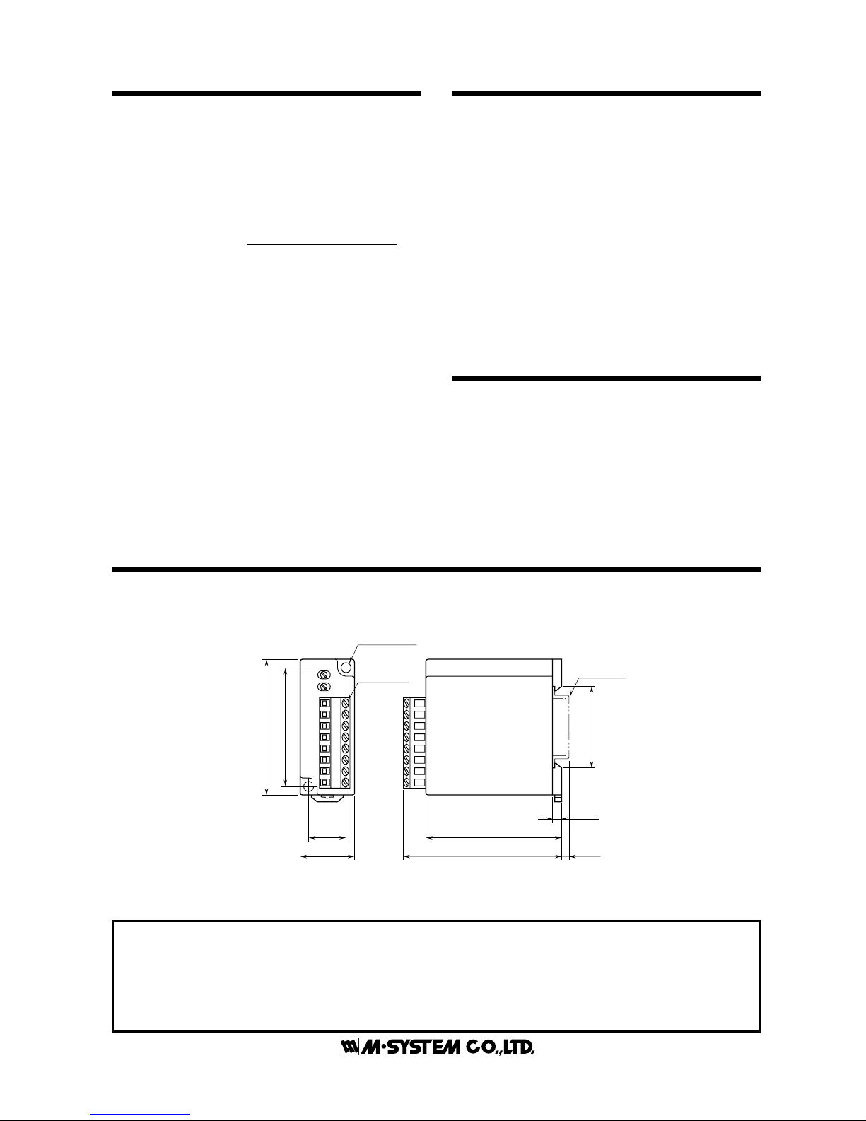
EXTERNAL DIMENSIONS mm (inch)
CHECKING
1) Terminal wiring: Check that all cables are correctly
connected according to the connection diagram.
2) Input: Check voltage across the terminal 4 (+) – 5 (–) with
a voltmeter to show 0V at 0% potentiometer input and the
same voltage as that across 3 (+) –␣ 5 (–) at 100% input.
3) Output: Check that the load is within the permissible
limit including wiring resistance.
Supply Voltage (V) –␣ 12 (V)
Load Resistance (Ω) =
0.02 (A)
(including leadwire resistance)
4) Monitoring indicator should be at the max. of 10Ω.
ADJUSTMENT PROCEDURE
This unit is calibrated at the factory with the total resistance
input, therefore you do not need any calibration if you use the
potentiometer's total resistance.
When you don't use the total resistance or in case of regular
calibration, adjust the output as explained in the following.
■ HOW TO CALIBRATE THE OUTPUT SIGNAL
Use a signal source and measuring instruments of sufficient
accuracy level. Turn the power supply on and warm up for
more than 10 minutes.
1) ZERO: Apply 0% input and adjust output to 0%.
2) SPAN: Apply 100% input and adjust output to 100%.
3) Check ZERO adjustment again with 0% input.
4) When ZERO value is changed, repeat the above procedure
1) – 3).
MAINTENANCE
Regular calibration procedure is explained below:
■ CALIBRATION
Warm up the unit for at least 10 minutes. Apply 0%, 25%,
50%, 75% and 100% input signal. Check that the output
signal for the respective input signal remains within accuracy described in the data sheet. When the output is out of
tolerance, recalibrate the unit according to the "ADJUSTMENT PROCEDURE" explained earlier.
35.4 (1.39)
DIN RAIL
35mm wide
18 (.70)
25 (.98)
53 (2.08)
60 (2.36)
60 (2.36)
4 (.15)
3.3 (.12)70 (2.76)
2–4.3 (.17) dia.
MTG HOLE
DIN
TERMINALS
1
2
3
4
5
6
7
8
•When mounting, no extra space is needed between units.
M-SYSTEM WARRANTY
M-System warrants such new M-System product which it manufactures to be free from defects in materials and workmanship during the 36-month period following the date that such
product was originally purchased if such product has been used under normal operating conditions and properly maintained, M-System's sole liability, and purchaser's exclusive remedies,
under this warranty are, at M-System's option, the repair, replacement or refund of the purchase price of any M-System product which is defective under the terms of this warranty. To
submit a claim under this warranty, the purchaser must return, at its expense, the defective M-System product to the below address together with a copy of its original sales invoice.
THIS IS THE ONLY WARRANTY APPLICABLE TO M-SYSTEM PRODUCT AND IS IN LIEU OF ALL OTHER WARRANTIES, EXPRESS OR IMPLIED, INCLUDING ANY IMPLIED
WARRANTIES OF MERCHANTABILITY OR FITNESS FOR A PARTICULAR PURPOSE. M-SYSTEM SHALL HAVE NO LIABILITY FOR CONSEQUENTIAL, INCIDENTAL OR
SPECIAL DAMAGES OF ANY KIND WHATSOEVER.
M-System Co., Ltd., 5-2-55, Minamitsumori, Nishinari-ku, Osaka 557-0063 JAPAN, Phone: (06) 6659-8201, Fax: (06) 6659-8510, E-mail: info@m-system.co.jp
 Loading...