

Page 1

SHSP
P. 1 / 4EM-9308-A Rev.4
8-PORT ETHERNET SWITCH
(with surge protector)
MODEL
SHSP
INSTRUCTION MANUAL
BEFORE USE ....
Thank you for choosing M-System. Before use, please check
contents of the package you received as outlined below.
If you have any problems or questions with the product,
please contact M-System’s Sales Office or representatives.
This product is for use in general industrial environments,
therefore may not be suitable for applications which require
higher level of safety (e.g. safety or accident prevention systems) or of reliability (e.g. vehicle control or combustion control systems).
For safety, installation and maintenance of this product
must be conducted by qualified personnel.
■ PACKAGE INCLUDES:
Ethernet switch ............................................................
(1)
■ MODEL NO.
Confirm Model No. marking on the product to be exactly
what you ordered.
■ INSTRUCTION MANUAL
This manual describes necessary points of caution when
you use this product, including installation, connection and
basic maintenance procedures.
POINTS OF CAUTION
■ CONFORMITY WITH EC DIRECTIVES
• The equipment must be mounted inside a panel.
• The actual installation environments such as panel con
figurations, connected devices, connected wires, may affect
the protection level of this unit when it is integrated in
a panel system. The user may have to review the CE requirements in regard to the whole system and employ additional protective measures to ensure the CE conformity.
■ POWER INPUT RATING & OPERATIONAL RANGE
• Locate the power input rating marked on the product and
confirm its operational range as indicated below:
100 – 240V AC rating: 85 – 264V, 47 – 66 Hz, approx. 8 – 11VA
24V DC rating: 24V ±10%, approx. 5.5W
■ SAFETY PRECAUTION
• Before you remove the unit or mount it, turn off the power
supply and input signal for safety.
■ ENVIRONMENT
• Indoor use
• When heavy dust or metal particles are present in the air,
install the unit inside proper housing with sufficient ventilation.
• Do not install the unit where it is subjected to continuous
vibration. Do not subject the unit to physical impact.
• Environmental temperature must be within -5 to +60°C
(23 to 140°F) with relative humidity within 30 to 95% RH
in order to ensure adequate life span and operation.
• Be sure that the ventilation slits are not covered with ca
-
bles, etc.
■ WIRING
• Wrong connection may damage the unit.
• Do not install cables (power supply, network and output)
close to noise sources (relay drive cable, high frequency
line, etc.).
• Do not bind these cables together with those in which
noises are present. Do not install them in the same duct.
• Mixing with other networks may cause malfunction.
Page 2
SHSP
P. 2 / 4EM-9308-A Rev.4
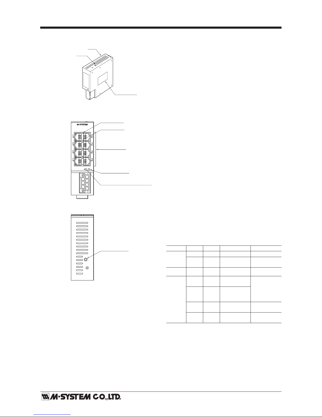
COMPONENT IDENTIFICATION
• Status
Bicolor LED which changes from green to red according to
the unit’s status.
Green
LAN ports are in normal communication status.
Red
Communication is lost due to the control circuit failure.
Replace the unit.
Alarm contact output is turned on.
• Surge Protector
Tricolor LED which changes from green to orange to red
according to the unit’s status.
OFF
When the power supply is turned on for the first time af
ter the unit has been installed, the LED is OFF indicating
that it is in the initial state.
Green
The unit has been subjected to a lightning surge for the
first time. The LED turns on only when the power is supplied.
Orange
The internal surge protector is close to its end of life. Im
mediate replacing the unit is recommended.
Red
The internal surge protector has degraded and is in ab
normal status or at its end of life.
Immediate replacing the unit is required.
Alarm contact output is turned on.
• Startup LED Operation
Both Status and Protector LED turns to orange color for
approximately 1 second when the power supply is turned
on while the internal microprocessor is initialized. Status
of the unit and its surge protector as explained above is irrelevant.
Indicator Functions
LED
COLOR ALARM
UNIT STATUS
REPLACEMENT
Status
Green OFF Normal No need
Red ON
Control circuit
failure
Immediately
required
LED
COLOR ALARM
DISCHARGE
ELEMENT
REPLACEMENT
Protector
OFF OFF
Normal (no
surge)
No need
Green OFF
Normal
(one or multi-
ple surge hits)
Orange OFF
Close to
end-of-life
Immediately
recommended
Red ON
End-of-life
(degraded)
Immediately
required
7
6
5
4
3
2
1
LAN Port (x 8)
RJ45 Connector
100M LED (x 8)
■ FRONT VIEW
■ TOP VIEW
LINK LED (x 8)
Surge Protector Life Monitor LED
Device status LED
Ethernet Switch
MODEL:SHSP
PORT 100/10M
COMM
Configurator Jack
COMM
(front)
Status
Surge Protector
Body
COMM
Specifications
Page 3

SHSP
P. 3 / 4EM-9308-A Rev.4
INSTALLATION
Set the unit so that its DIN rail adaptor is at the bottom.
Position the upper hook at the rear side of the unit on the
DIN rail and push in the lower. When removing the unit,
push down the DIN rail adaptor utilizing a minus screwdriver and pull.
TERMINAL CONNECTION
Connect the unit as in the diagram below.
1
2
• Dual Redundant Power Supply
SHSP
24VDC
Power
3
1
2
• Single Power Supply
SHSP
24VDC
Power
3
Connect independent power sources to both terminals 1 – 3 and 2 – 3.
Connect a power source to either of the terminals 1 – 3 or 2 – 3.
DIN Rail
(35 mm wide)
DIN Rail Adaptor
CONNECTING POWER SUPPLY / GROUND
■ POWER SUPPLY (DC power)
Two sets of power input terminals are available on this unit
(negative common).
In order to use two independent power sources for redundancy, connect each to the terminals 1 – 3 and 2 – 3 respectively. In this state, the unit can maintain its operation if
one of the power sources fails.
For single power supply, use either of these terminal sets.
■ GROUNDING
A surge protector is equipped at the LAN port to protect
the unit from surges entering through the LAN cable. It
is designed to direct the surges to the ground when they
enter the port as illustrated in the figure to the above right.
The G terminal, therefore, MUST be grounded. Grounding
resistance of 100Ω is recommended.
If you want to ground the system at multiple points in order
to separate noise interferences for information equipment
and for electric equipment:
1) When there is no potential difference between the two
grounding points, remove the shortcircuit bar connecting
FG and G terminals of this unit and connect the FG to
the ground for the information equipment, and the G to
that for the electric equipment.
2) When there is a potential difference, separate grounding
is not permitted. The shortcircuit bar must remain connected, and only the G terminal must be connected to the
grounding for electric equipment.
LAN Port
COMM
PC CONFIGURATOR
JACK
RJ-45 CONNECTOR
1
2
3
4
5
6
FG
7
G
ALARM CONTACT OUTPUT
Shortcircuit bar (attached)
+
+
–
POWER SUPPLY
(dual redundant)
Grounding
■ DC POWERED
LAN Port
COMM
PC CONFIGURATOR
JACK
RJ-45 CONNECTOR
2
3
4
5
6
FG
7
G
ALARM CONTACT OUTPUT
POWER SUPPLY
Shortcircuit bar (attached)
U
V
Grounding
■ AC POWERED
LOAD
Inductive
Load (Coil)
Varistor or
CR Circuit
• DC Powered
LOAD
Inductive
Load (Coil)
Diode, Varistor or
CR Circuit
■ Relay Protection
• AC Powered
Grounding
LAN Port
Lightning Surge
Surge Protector
SHSP
Control
Circuit
G
Page 4

SHSP
P. 4 / 4EM-9308-A Rev.4
M-SYSTEM WARRANTY
M-System warrants such new M-System product which it manufactures to be free from defects in materials and workmanship during the 36-month period following the date that such
product was originally purchased if such product has been used under normal operating conditions and properly maintained, M-System’s sole liability, and purchaser’s exclusive
remedies, under this warranty are, at M-System’s option, the repair, replacement or refund of the purchase price of any M-System product which is defective under the terms of this
warranty. To submit a claim under this warranty, the purchaser must return, at its expense, the defective M-System product to the below address together with a copy of its original
sales invoice.
THIS IS THE ONLY WARRANTY APPLICABLE TO M-SYSTEM PRODUCT AND IS IN LIEU OF ALL OTHER WARRANTIES, EXPRESS OR IMPLIED, INCLUDING ANY IMPLIED
WARRANTIES OF MERCHANTABILITY OR FITNESS FOR A PARTICULAR PURPOSE. M-SYSTEM SHALL HAVE NO LIABILITY FOR CONSEQUENTIAL, INCIDENTAL OR
SPECIAL DAMAGES OF ANY KIND WHATSOEVER.
M-System Co., Ltd., 5-2-55, Minamitsumori, Nishinari-ku, Osaka 557-0063 JAPAN, Phone: (06) 6659-8201, Fax: (06) 6659-8510, E-mail: info@m-system.co.jp
EXTERNAL DIMENSIONS mm (inch)
LAN CABLE
• To Use STP (Shielded Twisted Pair) Cable
Use of STP cables will enhance the protection effect, but
you must be aware that the LAN cable will be automatically
grounded at both ends as its shield will be connected to the
ground through the FG terminal.
If interference by common mode noise is suspected, use UTP
(Unshielded Twisted Pair) cable.
SURGE PROTECTION
This unit’s surge protection is applicable only to the LAN
ports. If the power input and alarm contact output terminals are connected to wires drawn from outside of the control panel, we recommend use of surge protectors for these
points, too.
Please contact M-System to select appropriate models.
MAINTENANCE
Confirm the unit’s status by referring to ‘Indicator Functions’ table in Page 2 and replace it to a new one if necessary.
130 (5.12)8 (.31)
40 (1.57)
6.3 (.25)
124 (4.88)
7
6
5
4
3
2
1
7–M3
SCREW
[2 (.08)]
35.4 (1.39)
DIN RAIL
35mm wide
 Loading...