

Page 1
MODEL: SD10
http://www.m-system.co.jp/ SD10 SPECIFICATIONS ES-6341 Rev.1 Page 1/8
Single Loop Controller Series
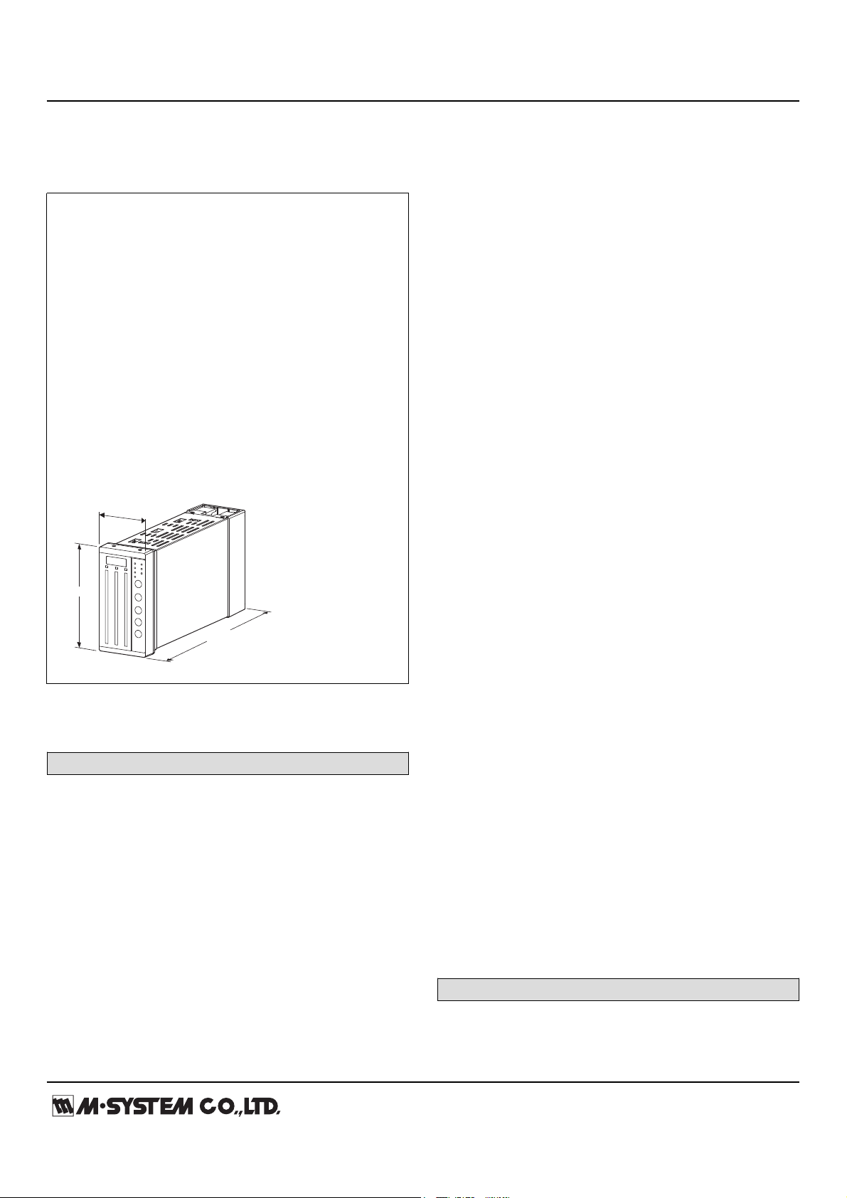
144 (5.67)
72 (2.83)
274 (10.79)
mm (inch)
BARGRAPH INDICATING ALARM
(with 4-digit digital meter, LED bar indicator)
Functions & Features
• Panel designed to match the SC series controllers.
• Displays a process variable in graphic bargraph of 101
LED segments
• 3 input channels
• Clear 4-digit digital meter
• Provides max. 4 alarm contact outputs
• LED brightness adjustments
• IP55 front cover
• Multi-color indicator (red, orange and green)
• Scale plate is easily replaceable
Typical Applications
• Panel operation for small-scale instrumentation
• Various alarm applications
[2] BAR LED COLOR (INPUT 2)
Same color availability as Input 1
[3] BAR LED COLOR (INPUT 3)
Same color availability as Input 1
[4] INPUT 1
Current
A: 4 – 20 mA DC (Input resistance 10 Ω)
Z: Specify current (See INPUT SPECIFICATIONS)
Voltage
6: 1 – 5 V DC (Input resistance 1 MΩ min.)
0: Specify voltage (See INPUT SPECIFICATIONS)
[5] INPUT 2
Same range availability as Input 1
[6] INPUT 3
Same range availability as Input 1
[7] DC OUTPUT 1
Y: Without
Current
A: 4 – 20 mA DC (Load resistance 550 Ω max.)
D: 0 – 20 mA DC (Load resistance 550 Ω max.)
Voltage
6: 1 – 5 V DC (Load resistance 10 kΩ min.)
0: Specify voltage (See OUTPUT SPECIFICATIONS)
MODEL: SD10-[1][2][3][4][5][6][7][8][9]-[10]
ORDERING INFORMATION
• Code number: SD10-[1][2][3][4][5][6][7][8][9]-[10]
Specify a code from below for each [1] through [10].
(e.g. SD10-RYGAA0A6Y-M2)
• Use Ordering Information Sheet (No. ESU-6341) for the I/O
codes, digital display range, decimal point position and
alarm setpoint.
• Bargraph range (Refer to 'SCALE PLATE')
[1] BAR LED COLOR (INPUT 1)
R: Red
Y: Amber
G: Green
B: Blue
1: Multi-color (red, orange and green), (See ‘External View.’)
[8] DC OUTPUT 2
Same range availability as DC Output 1
[9] DC OUTPUT 3
Same range availability as DC Output 1
[10] POWER INPUT
AC Power
M2: 100 – 240 V AC (Operational voltage range 85 – 264 V,
47 – 66 Hz)
DC Power
R: 24 V DC
(Operational voltage range 24 V ±10 %, ripple 10 %p-p max.)
SPARE PARTS
• Scale plate
Page 2
MODEL: SD10
http://www.m-system.co.jp/ SD10 SPECIFICATIONS ES-6341 Rev.1 Page 2/8
GENERAL SPECIFICATIONS
Construction: Panel flush mounting
Degree of protection: IP55; applicable to the front panel for
single unit mounted according to the specified panel cutout
Connection: M3.5 screw terminals (torque 1.0 N·m)
Screw terminal: Nickel-plated steel
Housing material: Flame-resistant resin (gray), steel
Setting: (Front button)
• Scaled range
• Alarm setpoint
• LED brightness
• Moving average
• DC output fine adjustment
• Others
(Refer to the instruction manual for details)
Isolation: Input 1 to input 2 to input 3 to supply output to DC
output 1 to DC output 2 to DC output 3 to alarm output 1 to
alarm output 2 to alarm output 3 to power to FG
Display zero adjustment (bargraph): -19 to +19 %
DC output zero adjustment: -19 to +19 %
Display span adjustment (bargraph): 81 to 119 %
DC output span adjustment: 81 to 119 %
Scale plate: Flame resistant resin (white scale & characters
on black base)
H & L alarm output delay: 0 sec. (factory setting;
fieldselectable between 0 and 15 sec. by 1 sec. increments)
Setpoint adjustment
HH [H setpoint] to 100 %
H [L setpoint] to [HH setpoint]
L [LL setpoint] to [H setpoint]
LL 0 % to [L setpoint]
Alarm deadband (hysteresis): 1 %
■ BARGRAPH
3 Bar-LEDs indicate scaled Input 1, 2 and 3 from 0 to 100 %.
LED: 101 segments, 100 mm (3.94") height, 3.0 mm (.12")
width
Display range: 0 to 100
Number of digits: Max. 4 digits (including decimal point and
negative sign)
Divisions: 22 – 100
Engineering unit: max. 6 characters
Bargraph display scale plate
•Detachable structure
•White characters on black base
■ DIGITAL DISPLAYS
With the Input indication selector (IND) display Input 1, 2
and 3 scaling values.
LED: Red; 4 digits; 10 mm (0.39") height, 24 mm (0.94")
width
Scaled range: -1999 to 0 to 9999
(Min. 3 significant digits)
Minimum scale value: 100 (3 digits, the decimal point
position disregarded)
Overrange: The indicator blinks when the input is out of the
range from -15 to +115 %.
The indicator shows '----' when the value after scaling is out
of the range.
Decimal point position: 10–1, 10–2, 10–3 or none
Zero indication: Higher-digit zeros are suppressed
■ LED BRIGHTNESS ADJUSTMENTS
3 levels of brightness available for the bargraph and the
digital indicator. (except alarm and mode setting status
LED)
Read rate: 5/s
Moving average sample number: 4 (factory setting; field
selectable among 1, 2, 4, 8 or 16)
SUPPLY OUTPUT
Output voltage:
24 V DC ±10 % with no load
18 V DC min. at 20 mA
Current rating: ≤ 22 mA DC
∙Shortcircuit protection
Current limited: Approx. 30 mA
INPUT SPECIFICATIONS
■ DC Current: 0 – 50 mA DC; input resistor incorporated
M-system selects input resistance from the following values
Max. signal (DC current at input 100 %) range: Input
resistance value
39 mA or more, not more than 50 mA: 5.1 Ω
20 mA or more, less than 39 mA: 10 Ω
16 mA or more, less than 20 mA: 12 Ω
10 mA or more, less than 16 mA: 20 Ω
5 mA or more, less than 10 mA: 39 Ω
1 mA or more, less than 5 mA: 200 Ω
Minimum span: 1 mA
Offset: Max. 1.5 times span
■ DC Voltage: -10 – +10 V DC
Input resistance: ≥ 1 MΩ
Minimum span: 0.1 V
Offset: Max. 1.5 times span
OUTPUT SPECIFICATIONS
■ DC Voltage
Choose output range from below.
0 – 1 V DC (Load resistance 2000 Ω min.)
0 – 10 V DC (Load resistance 20 kΩ min.)
0 – 5 V DC (Load resistance 10 kΩ min.)
-10 – +10 V DC (Load resistance 20 kΩ min.)
-5 – +5 V DC (Load resistance 10 kΩ min.)
For details, refer to the Ordering Information Sheet.
■ Alarm Output: Relay contact
Page 3
MODEL: SD10
http://www.m-system.co.jp/ SD10 SPECIFICATIONS ES-6341 Rev.1 Page 3/8
Rated load: 240 V AC @ 1 A (cos ø = 1)
30 V DC @ 1 A (resistive load)
Maximum switching voltage: 250 V AC or 30 V DC
Maximum switching power: 250 VA or 60 W
Minimum load: 5 V DC @ 10 mA
Mechanical life: 2 × 10⁷ cycles
INSTALLATION
Power consumption
AC:
Approx. 14 VA at 100 V
Approx. 17 VA at 200 V
Approx. 19 VA at 264 V
•DC: Approx. 7.3 W
Operating temperature: -5 to +55°C (23 to 131°F)
Operating humidity: 5 to 90 %RH (non-condensing)
Mounting: Panel flush mounting (high-density mounting in
horizontal direction)
Weight: 1.8 kg (4.0 lb)
PERFORMANCE in percentage of span
Accuracy: Input accuracy + output accuracy
• Input accuracy: ±0.1%
• Output accuracy:
±0.1 % DC output
±1 % ±1 digit (bargraph)
±0.1 % ±1 digit (digital indicator)
Temp. coefficient: ±0.015 %/°C (±0.008 %/°F)
Response time: ≤ 0.5 sec. (0 – 90%, moving average
sample number set to 4)
Line voltage effect: ±0.1 % over voltage range
Insulation resistance: ≥ 100 MΩ with 500 V DC
Dielectric strength:
1500 V AC @ 1 minute (Input 1 or Input 2 or input 3 or
supply output to DC output 1 or DC output 2 or DC output 3
to alarm output 1 or alarm output 2 or alarm output 3 to
power to FG)
500 V AC @ 1 minute (Input 1 to Input 2 to input 3 to supply
output)
500 V AC @ 1 minute (DC output 1 to DC output 2 to DC
output 3)
500 V AC @ 1 minute (alarm output 1 to alarm output 2 to
alarm output 3)
Page 4

MODEL: SD10
http://www.m-system.co.jp/ SD10 SPECIFICATIONS ES-6341 Rev.1 Page 4/8
SCALE PLATE
■ WHAT MUST BE SPECIFIED WHEN ORDERING
Please specify the bargraph scale range and engineering unit. The overvall scale plate design including the number of
divisions, division line length, character font is determined by M-System.
[Example] : Bargraph range 0 to 300 cm
Bargraph scale range: 0 – 300
Engineering unit for the bargraph: cm
■ TYPES OF DIVISIONS
Five (5) types of divisions are used depending upon the scale span, which determined by the following equation:
Scale Span = (Max. range value – Min. range value) x 10
where n = integer (used to limit the calculated scale span to the minimum of 1.1, below 11.0.)
The number of divisions is automatically determined by the scale span.
• Type 1: 1.1 ≤ Scale Span < 1.3
Number of divisions: 22 to 25.9
Scale: Starts at 0, increments by 0.02 / 0.2 / 2 / 20 /
200. Min. and max. values indicated. 4 digits
including negative sign and decimal point.
Division lines: Long, Short, Medium, Short, Long
(4 divisions repeated)
• Type 3: 2.0 ≤ Scale Span < 2.6
Number of divisions: 40 to 51.9
Scale: Starts at 0, increments by 0.05 / 0.5 / 5 / 50 /
500. Min. and max. values indicated. 4 digits
including negative sign and decimal point.
Division lines: Long, Short, Medium, Short, Medium,
Short, Medium, Short, Medium, Short, Long
(10 divisions repeated)
Minimum
Divisions
Maximum
Divisions
Bipolar
Scale
10
11
8
6
4
2
0
600
400
200
0
-200
-400
0.2
0
-600
0.4
0.6
0.8
1.0
1.2
1.29
Minimum
Divisions
Maximum
Divisions
Bipolar
Scale
120
100
50
0
-50
-100
-120
0
0
0.5
1
1.5
2
2.59
5
10
15
20
• Type 2: 1.3 ≤ Scale Span < 2.0
Number of divisions: 26 to 39.9
Scale: Starts at 0, increments by 0.03 / 0.3 / 3 / 30 /
300. Min. and max. values indicated. 4 digits
including negative sign and decimal point.
Division lines: Long, Short, Medium, Short, Medium,
Short, Long (6 divisions repeated)
n
• Type 4: 2.6 ≤ Scale Span < 5.5
Number of divisions: 26 to 54.9
Scale: Starts at 0, increments by 0.05 / 0.5 / 5 / 50 /
500. Min. and max. values indicated. 4 digits
including negative sign and decimal point.
Division lines: Long, Medium, Medium, Medium,
Medium, Long (5 divisions repeated)
Minimum
Divisions
Maximum
Divisions
Bipolar
Scale
0.0
0.3
0.6
0.9
1.2
1.5
1.8
0.6
0.3
0.0
-0.3
-0.6
-0.8
0.8
1.99
0
30
60
90
120
130
Minimum
Divisions
Maximum
Divisions
Bipolar
Scale
250
200
150
100
50
0
-50
-100
-150
-200
-2500 0
0.5
1
1.5
2
2.5
3
3.5
4
4.5
5
5.49
50
100
150
200
250
260
Page 5

MODEL: SD10
http://www.m-system.co.jp/ SD10 SPECIFICATIONS ES-6341 Rev.1 Page 5/8
0.5
0.4
0.3
0.2
0.1
0
-0.1
-0.2
-0.3
-0.4
-0.5
0
100
200
300
400
500
550
0
1
2
3
4
5
6
7
8
9
10
10.9
Minimum
Divisions
Maximum
Divisions
Bipolar
Scale
• Type 5: 5.5 Scale Span < 11.0
Number of divisions: 27.5 to 54.9
Scale: Starts at 0, increments by 0.01 / 0.1 / 1 / 10 /
100 / /1000. Min. and max. values indicated. 4
digits including negative sign and decimal point.
Division lines: Long, Medium, Medium, Medium,
Medium, Long
(5 divisions repeated)
[Example] : Bargraph range 0 to 300 cm (Type 4)
Digital indicator range 0.00 to 6.75 m3
(Type 4)
Left scale range: 0 – 300
Left scale unit (bargraph): cm
Center and right bar scale: None
300
250
cm
200
150
100
50
0
EXTERNAL VIEW
2
8
9
10
11
12
1 6 7
3 4 5
1. Digital meter
2. Digital meter Selector LED
(Displays which of the 3 inputs value is indicating)
3. Input 1 bargraph meter
4. Input 2 bargraph meter
5. Input 3 bargraph meter
6. Alarm indicator
7. Mode setting status LED
8. Input indication selector (IND)
9. Mode selector (M)
10. Manual operation button (UP)
11. Acceleration button (FAST)
(Acclerates the operation by pressing simultaneously
with UP or DOWN button)
12. Manual operation button (DOWN)
HH Setpoint
H Setpoint
L Setpoint
LL Setpoint
PV Indicator
• Bar Color Pattern
orange orange
green
orange
Input < L L < Input < H H < Input
green
red
H
L
Page 6

MODEL: SD10
http://www.m-system.co.jp/ SD10 SPECIFICATIONS ES-6341 Rev.1 Page 6/8
EXTERNAL DIMENSIONS & TERMINAL ASSIGNMENTS unit: mm (inch)
14
15
16
17
18
19
20
21
22
23
24
25
26
1
2
3
4
5
6
7
8
9
10
11
12
13
40
41
42
43
44
45
46
47
48
49
50
51
52
27
28
29
30
31
32
33
34
35
36
37
38
39
144 (5.67)
164 (6.46)
MOUNTING BRACKET
72 (2.83)
24 (.94)
250 (9.84)
67.5 (2.66)
137.5 (5.41)
TERMINAL COVER
52–M3.5 SCREW
138
68 [68+72×(n - 1)]
+1
0
+0.7
0
Panel thickness 2.3 – 20
138
+1
0
+1
0
■ PANEL CUTOUT unit: mm
• Single mounting • Clustered mounting
n = number of units
PANEL CUTOUT unit: mm
■ CAUTION
• Degree of protection, IP55 is applicable to the front panel of the unit with single mounting according to the specified panel
cutout. Ensure that there is no compromise in the unit's protection against water and dust after installation.
• Install the unit to vertical panel so that its digital meter is at the upper side. Installing by other direction will cause
degradation of life span or performance due to rise of the internal temperature.
• Ensure that there is sufficient space for ventilation inside a panel. Do not install above the devices that generate high
temperature such as heaters, transformers or resistors. Observe at the minimum of 30 mm (1.2”) in all directions for
maintenance purpose.
Page 7

MODEL: SD10
http://www.m-system.co.jp/ SD10 SPECIFICATIONS ES-6341 Rev.1 Page 7/8
SCHEMATIC CIRCUITRY & CONNECTION DIAGRAM
Bargraph LED
CH1
(IND)
+
–
INPUT 1 (Ai1)
+
–
+
–
INPUT 2 (Ai2)
+
–
+
–
INPUT 3 (Ai3)
SUPPLY OUTPUT
+
–
29
+
30
–
24 V DC
Supply
33
32
44
43
47
46
(M)
(UP)
(FAST)
(DOWN)
3
+
4
–
DC OUTPUT 1 (Ao1)*
12
13
U(+)
V(–)
26
FG
14
1
15
2
HHa1
Hc1, HHc1
HHb1
Ha1
HH OUTPUT 1
H OUTPUT 1
40
41
27
28
LLa1
Lc1, LLc1
LLb1
La1
LL OUTPUT 1
L OUTPUT 1
CH2
5
+
6
–
DC OUTPUT 2 (Ao2)*
18
16
19
17
HHa2
Hc2, HHc2
HHb2
Ha2
22
20
23
21
LLa2
Lc2, LLc2
LLb2
La2
CH3
7
+
8
–
24
10
25
11
HHa3
Hc3, HHc3
HHb3
Ha3
51
52
38
39
LLa3
Lc3, LLc3
LLb3
La3
34
35
36
37
31
42
45
48
49
50
9
HH OUTPUT 2
H OUTPUT 2
LL OUTPUT 2
L OUTPUT 2
DC OUTPUT 3 (Ao3)*
HH OUTPUT 3
H OUTPUT 3
LL OUTPUT 3
L OUTPUT 3
Isolation
Isolation
Isolation
Digital Meter
IsolationIsolation
Output
Circuit
IsolationIsolation
Output
Circuit
IsolationIsolation
Output
Circuit
POWER
Input A/D
Converter
Input A/D
Converter
Input A/D
Converter
Digital
Computation
CONNECTION (2-Wire transmitter)
BC+
29
30
+
Supply output
Input 1, 2 or 3 (Current input only)
*
Not available for output code /Y
–
+
–
–
2-Wire
transmitter
**
**
Not applicable to smart transmitters
Page 8

MODEL: SD10
http://www.m-system.co.jp/ SD10 SPECIFICATIONS ES-6341 Rev.1 Page 8/8
Specifications are subject to change without notice.
 Loading...