

Page 1

R7ML-EC16D
P. 1 / 3
EM-7805-AA Rev.1
5-2-55, Minamitsumori, Nishinari-ku, Osaka 557-0063 JAPAN
Phone: +81(6)6659-8201 Fax: +81(6)6659-8510 E-mail: info@m-system.co.jp
PNP TRANSISTOR OUTPUT EXTENSION MODULE, 16 points
(MECHATROLINK-I / -II , short circuit protection)
MODEL
R7ML-EC16D
INSTRUCTION MANUAL
BEFORE USE ....
Thank you for choosing M-System. Before use, please check
contents of the package you received as outlined below.
If you have any problems or questions with the product,
please contact M-System’s Sales Office or representatives.
■ PACKAGE INCLUDES:
Discrete output extension module ................................. (1)
■ MODEL NO.
Confirm Model No. marking on the product to be exactly
what you ordered.
■ INSTRUCTION MANUAL
This manual describes necessary points of caution when
you use this product, including installation, connection and
basic maintenance procedures.
POINTS OF CAUTION
■ CONFORMITY WITH EU DIRECTIVE
•The actual installation environments such as panel configurations, connected devices and connected wires may
affect the protection level of this unit when it is integrated in a panel system. The user may have to review the CE
requirements in regard to the whole system and employ
additional protective measures to ensure CE conformity.
■ POWER INPUT RATING & OPERATIONAL RANGE
•Locate the power input rating marked on the product and
confirm its operational range as indicated below:
24V DC rating: 24V ±10%, approx. 20mA
■ GENERAL PRECAUTIONS
•Before you remove the unit or mount it, turn off the power
supply and output signal for safety.
■ ENVIRONMENT
•Indoor use.
•When heavy dust or metal particles are present in the
air, install the unit inside proper housing with sufficient
ventilation.
•Do not install the unit where it is subjected to continuous
vibration. Do not subject the unit to physical impact.
•Environmental temperature must be within 0 to 55°C (32
to 131°F) with relative humidity within 30 to 90% RH in
order to ensure adequate life span and operation.
■ WIRING
•Do not install cables close to noise sources (relay drive
cable, high frequency line, etc.).
•Do not bind these cables together with those in which
noises are present. Do not install them in the same duct.
■ AND ....
•The unit is designed to function as soon as power is supplied, however, a warm up for 10 minutes is required for
satisfying complete performance described in the data
sheet.
COMPONENT IDENTIFICATION
0 1 2 3 4 5 6 7 8 9 A B C D E F
10 11 12 13
2341
15 16 17 18
7896145
Discrete Output Status Indicator LED
Output Terminals
■ DISCRETE OUTPUT STATUS INDICATOR LED
Discrete output extension modules have LED indicators
showing output signal status.
Contact ON : LED ON
Contact OFF : LED OFF
■ OUTPUT TERMINAL ASSIGNMENT
10
+24V11Y112Y3
10V2Y03
Y2
13
Y5
4
Y4
14
Y7
5
Y6
15
Y9
6
Y8
16
YB
7
YA
17
YD
8YC9
YE
18
YF
NO. ID FUNCTION NO. ID FUNTION
1 0V 0V 10 +24V 24V DC (common)
2 Y0 Output 0 11 Y1 Output 1
3 Y2 Output 2 12 Y3 Output 3
4 Y4 Output 4 13 Y5 Output 5
5 Y6 Output 6 14 Y7 Output 7
6 Y8 Output 8 15 Y9 Output 9
7 YA Output 10 16 YB Output 11
8 YC Output 12 17 YD Output 13
9 YE Output 14 18 YF Output 15
Page 2
R7ML-EC16D
P. 2 / 3
EM-7805-AA Rev.1
5-2-55, Minamitsumori, Nishinari-ku, Osaka 557-0063 JAPAN
Phone: +81(6)6659-8201 Fax: +81(6)6659-8510 E-mail: info@m-system.co.jp
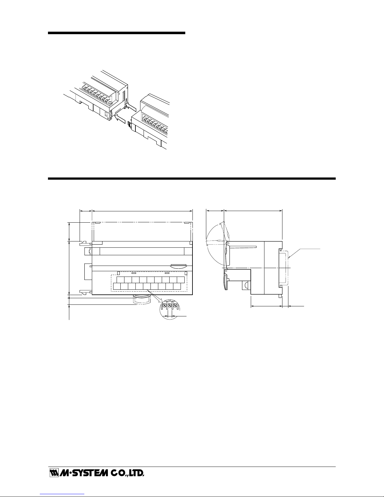
CONNECTING THE EXTENSION MODULE
1) Remove the extension connector cover located at the side
of the basic module.
2) Connect the extension module.
3) Mount the combined module on a DIN rail.
EXTERNAL DIMENSIONS unit: mm (inch)
11.5
(.45)
10 11 12 13
2341
15 16 17 18
78
9
6145
94 (3.70)
30 (1.18)
[5 (.20)]
DIN RAIL
35mm wide
54 (2.13)
17 (.66)
18–M3 SCREW
TERMINALS
for OUTPUT
6 (.24)
3 (.12)5.5 (.22)
50 (1.97)
18.5 (.73)
Page 3

R7ML-EC16D
P. 3 / 3
EM-7805-AA Rev.1
5-2-55, Minamitsumori, Nishinari-ku, Osaka 557-0063 JAPAN
Phone: +81(6)6659-8201 Fax: +81(6)6659-8510 E-mail: info@m-system.co.jp
CONNECTION DIAGRAM
Connect the unit as in the diagram below.
EXTENSION CONNECTOR
10
17
18
1
YD
16
YB
0V
YF
15
Y9
14
Y7
13
Y5
12
Y3
11
Y1
9
YE
8
YC
7
YA
6
Y8
5
Y6
4
Y4
3
Y2
+24V
Y0
2
■ Output Connection Example
10
1
2
Y0
0V
+24V
–
+
18
YF
WIRING INSTRUCTIONS
■ SCREW TERMINAL
Torque: 0.5 N·m
■ SOLDERLESS TERMINAL mm (inch)
Refer to the drawing below for recommended ring tongue
terminal size. Spade tongue type is also applicable. Solderless terminal:
Applicable wire size: 0.25 to 1.65 mm
2
(AWG 22 to 16)
Recommended manufacturer: Japan Solderless Terminal
MFG. Co., Ltd, Nichifu Co., Ltd
6 (.24) max
3.3 (.13) max
mm (inch)
I/O DATA DESCRIPTION
015
0:OFF 1:ON
Output 0
Output 1
Output 2
Output 3
Output 15
Output 7
Output 8
■ DISCRETE OUTPUT
 Loading...